HOLIDAY DONATION DRIVE - SUPPORT MSW - DO YOUR PART TO KEEP THIS GREAT FORUM GOING! (Only 44 donations so far out of 49,000 members - C'mon guys!)
×


KeithAug
-
Posts
3,957 -
Joined
-
Last visited
Content Type
Profiles
Forums
Gallery
Events
Everything posted by KeithAug
-
 Look on the bright side - it will make a good brake.
 -
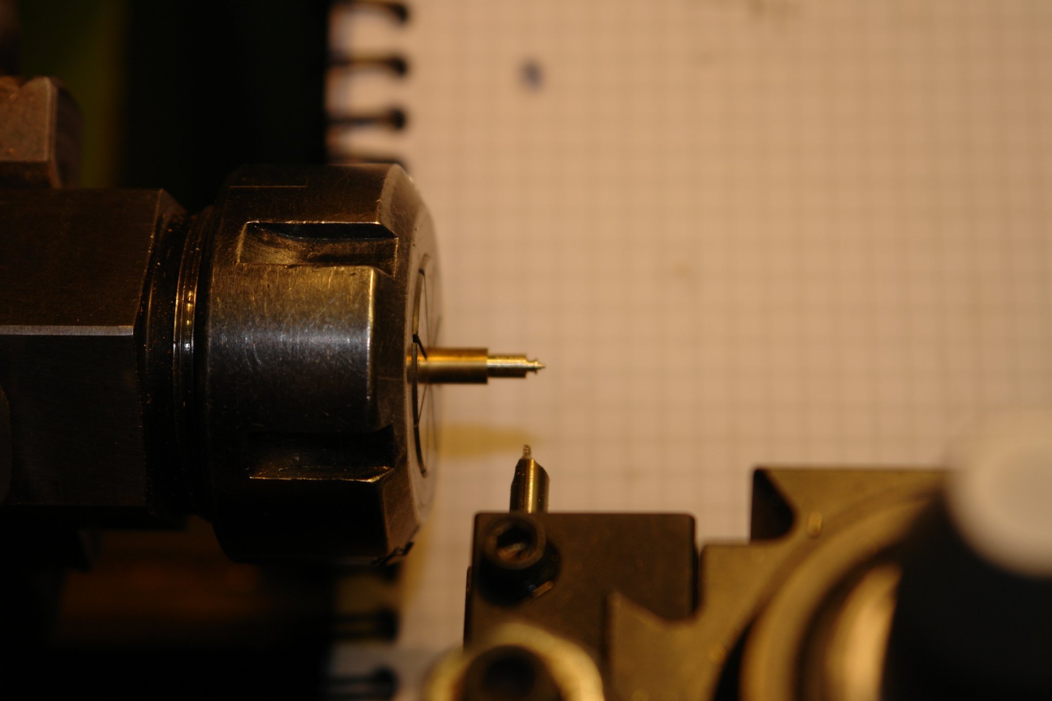
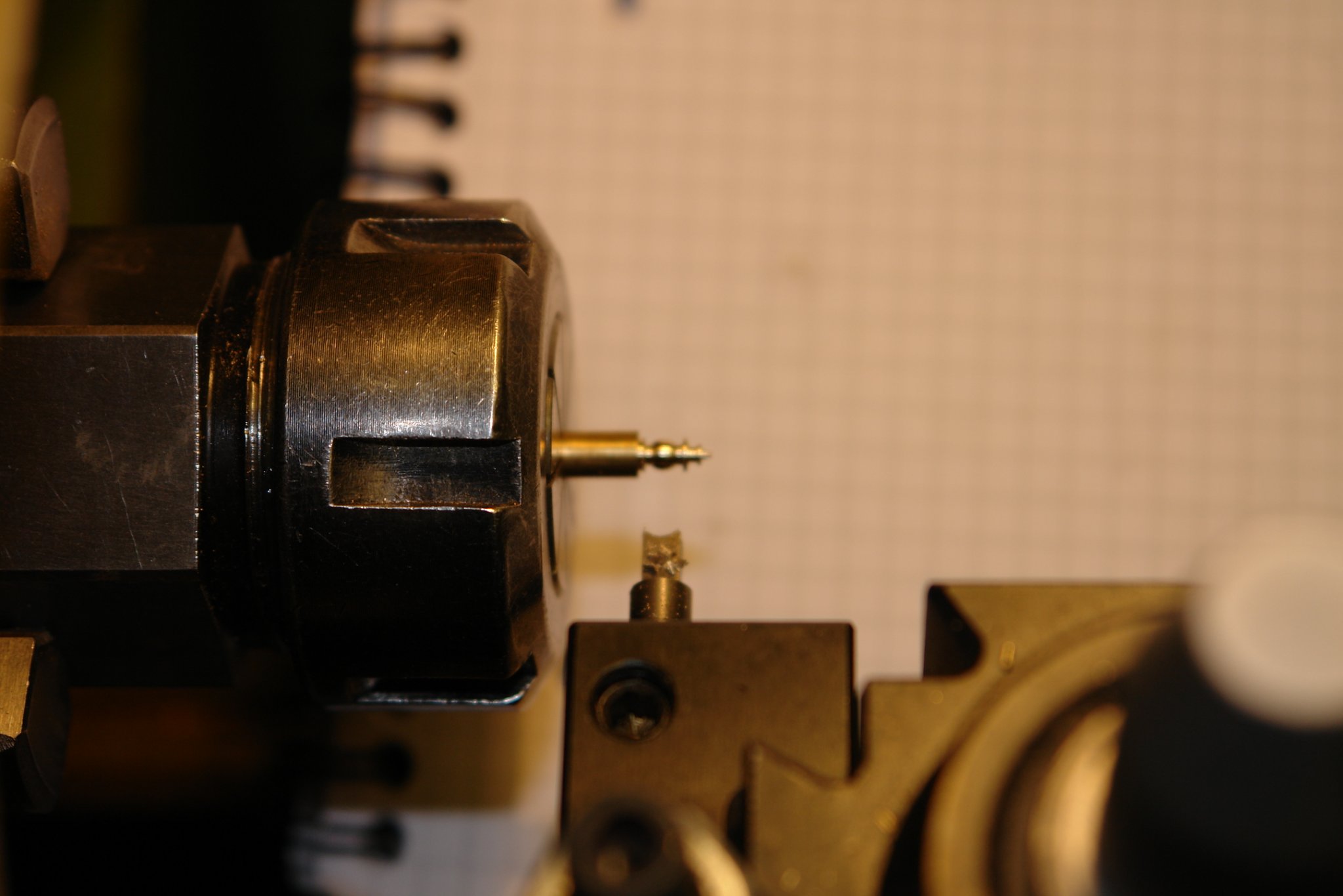
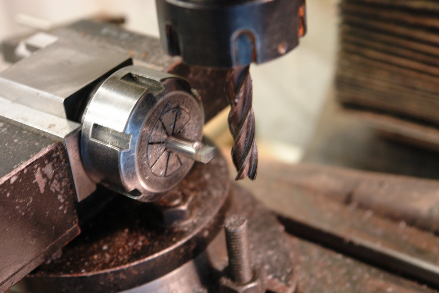
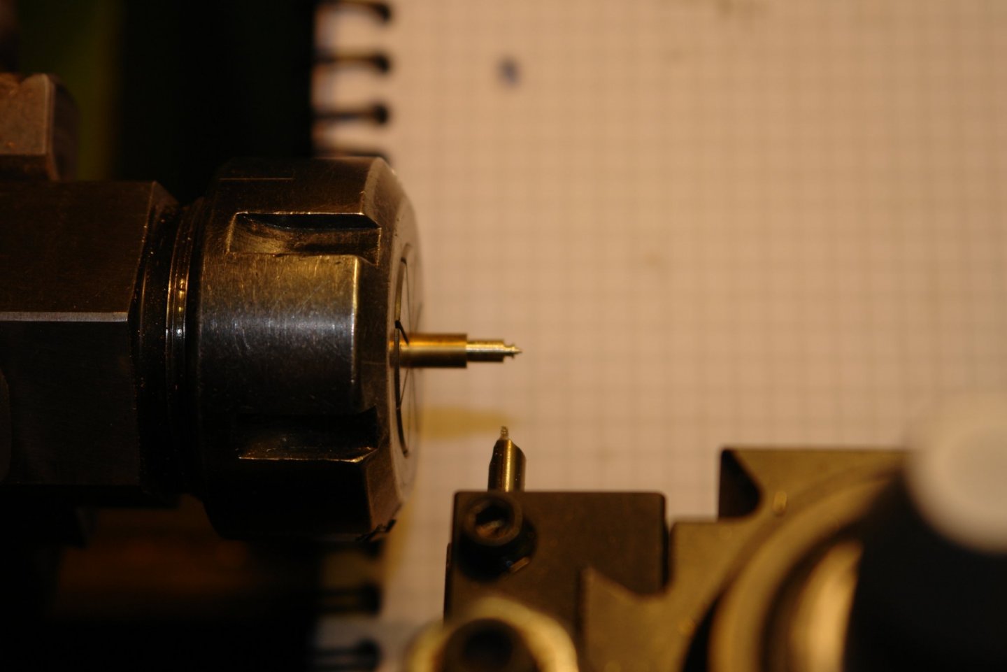
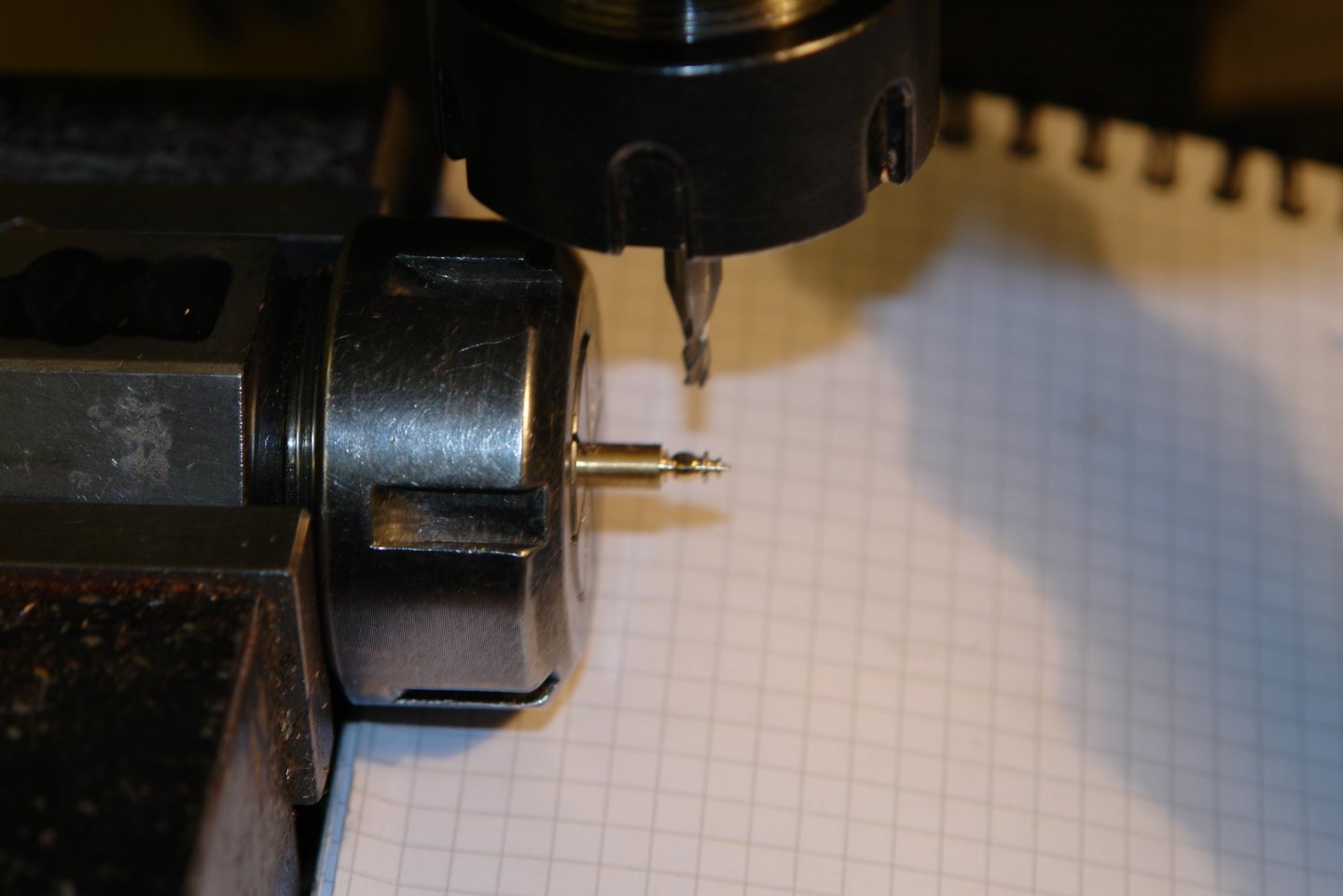
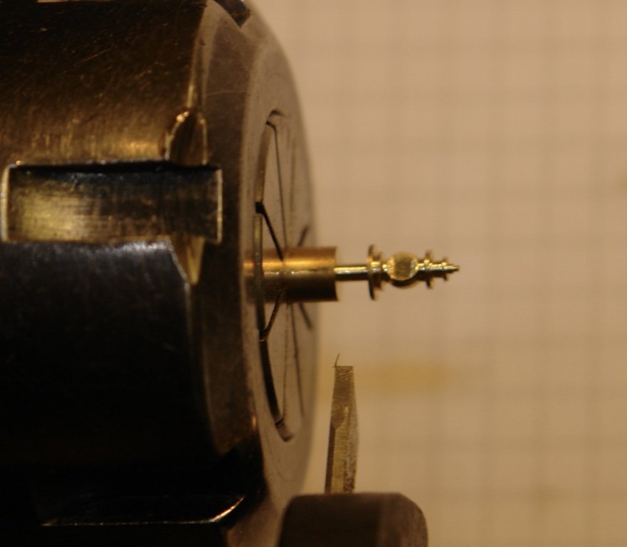
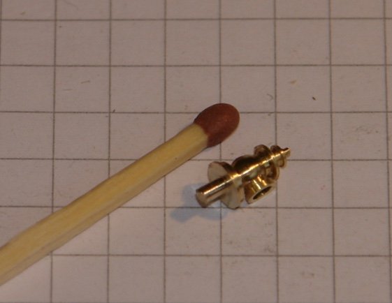
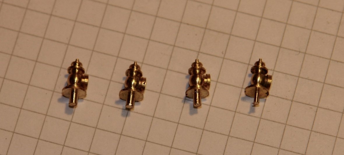
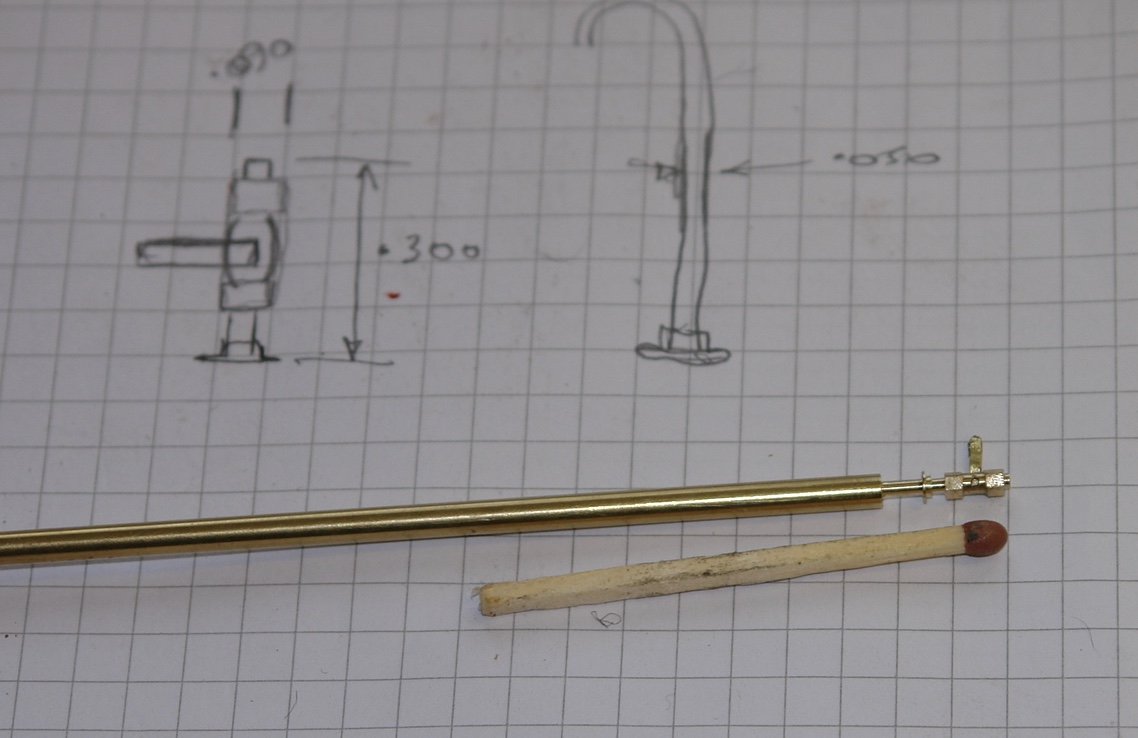
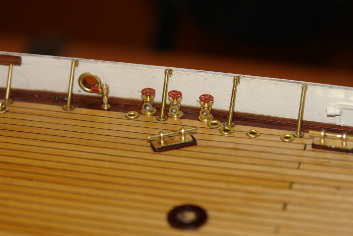
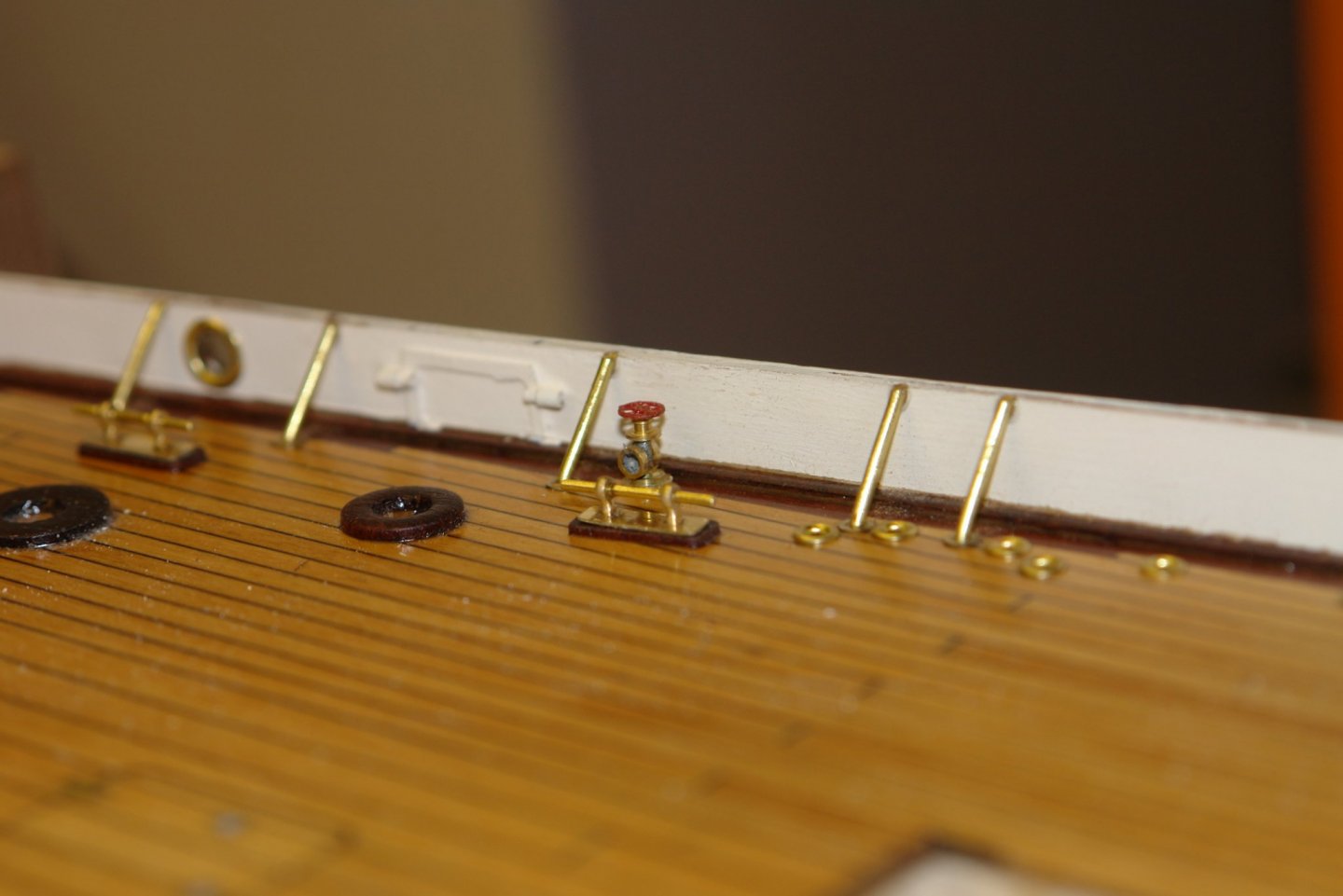
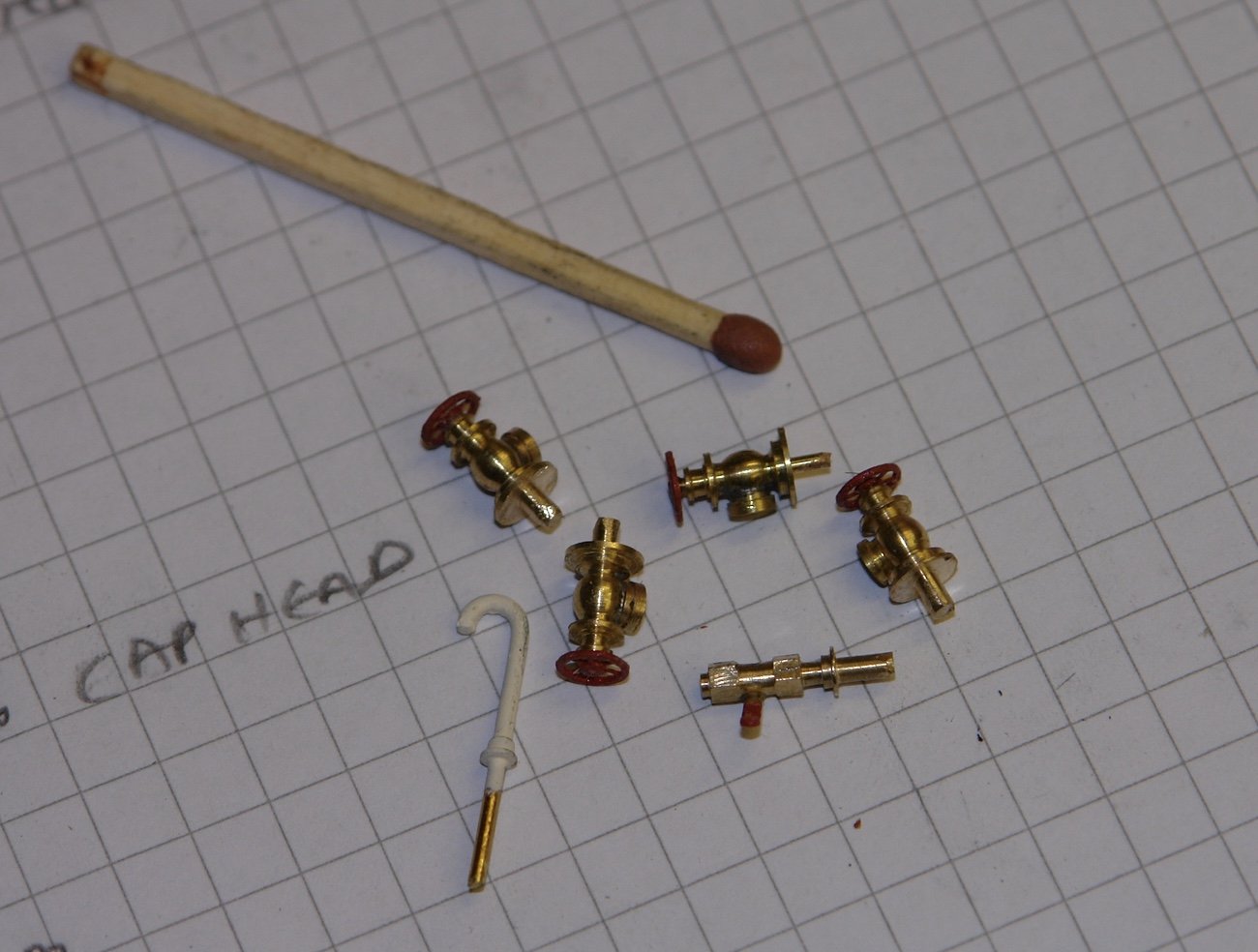
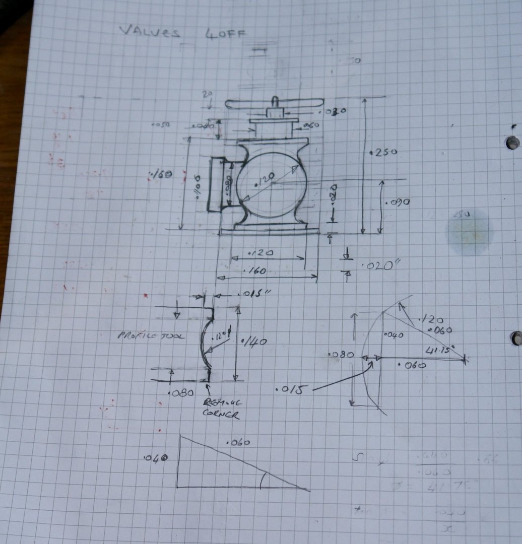
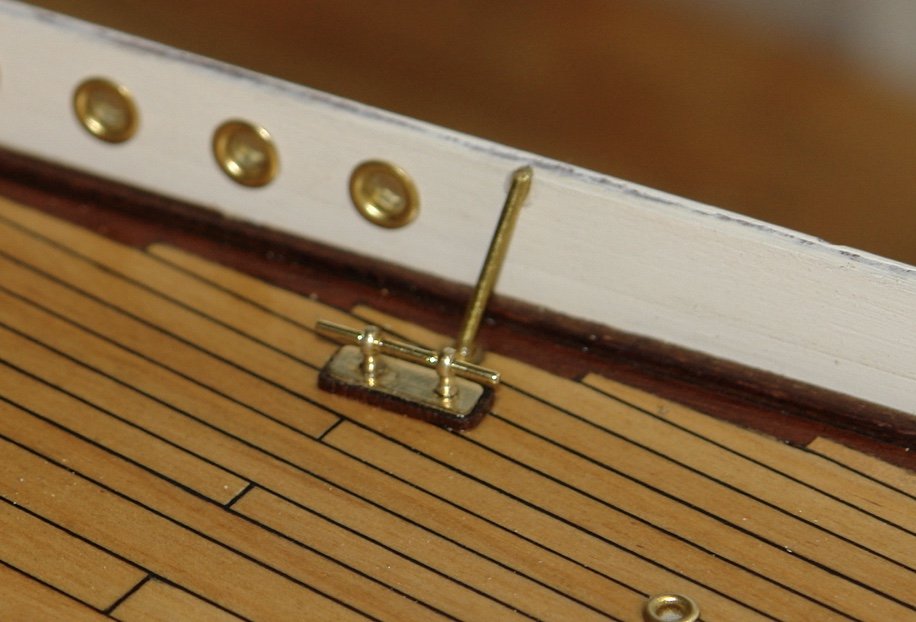
Right, that's it - the shipyard is closed for Christmas, the wood burner is roaring, the house is trimmed and the gin is flowing freely. Merry Christmas to you all. I have successfully completed my day and half of valve and vent work. I started by milling the profile tool, the silver steel bar was squared off and then a 3mm (.120) diameter cutter was wound .015" into the square end to create the required radius of the spherical part of the valve. A 3/16" rod was then mounted in a hex collet block and placed in the lathe and the various diameters of the valve body were turned. Following this the profile tool was placed in the toolholder and plunged in to form the ball and the necks on either side of the ball. The hex block was then removed from the lathe and mounted in the mill. A small cutter was then used to plane off part of the sphere to form a flat. Then it was back to the lathe to turn a mounting spigot. The right angled part of the valve was then turned as a separate part and this was then soldered to the flat previously machined on the sphere. The match in the next photo gives a good impression of size and fortunately it is more in focus than the previous set. (maybe Santa will bring me a new camera). I needed 4 in total and over the course of a few hours I had them. Then it was on to the single in line ball valve - made from a 3/32" rod. This was first mounted in a hex collet block and milled to a hexagonal profile. The hex section was then cross drilled to take the handle and the collet block was mounted in the lathe to turn the waist and the mounting spigot. The handle was made from a flattened piece of fine brass wire with the end left round to fit the cross hole. Finally the vent pipe was made from wire with a small flange soldered to the base and painted white. About 30 years ago I bought an etched brass sheet of various types and shapes of hand wheels. I selected the most appropriate ones, painted them red and CA glued them to the valve stems. All 6 parts are shown in the next photo. The final step was to mount them adjacent to the bulwarks.

-
Pat - thank you for your very full and detailed explanation of the process. It sounds like the sort of job I need to do sober - so maybe not in the next few days. The most difficult thing for me would be persuading my better half to venture into the unheated workshop to provide an extra pair of hands. If I press this point I might well enter the New Year searching for a new wife. You have eased my fears that the glued approach can work. Merry Christmas - Santa can't be very far away in your part of the world, I hope he delivers some much needed rain, we have plenty to spare, maybe you can have some of our.
-
Coming along very nicely Phil. Amazing amount of work in these old warships models. Happy Christmas to you and yours.
-
Very kind Keith. I don't really need it for some time so I will keep looking over here. If i don't find anything as good I will get back to you. How many links per inch is it?
-
Pat - yes I was thinking that glue would be the solution, but how did you hold the curvature while the glue dried? Thank you John. Bedford - interesting thought.
-
Exquisite work on the rigging, so very precise.
- 1,035 replies
-
- 5
-

-
- royal katherine
- ship of the line
- (and 1 more)
-
Nice work on the rigging Keith, where did you get the chain from? Also lovely spindle backed chair. Merry Christmas.
-
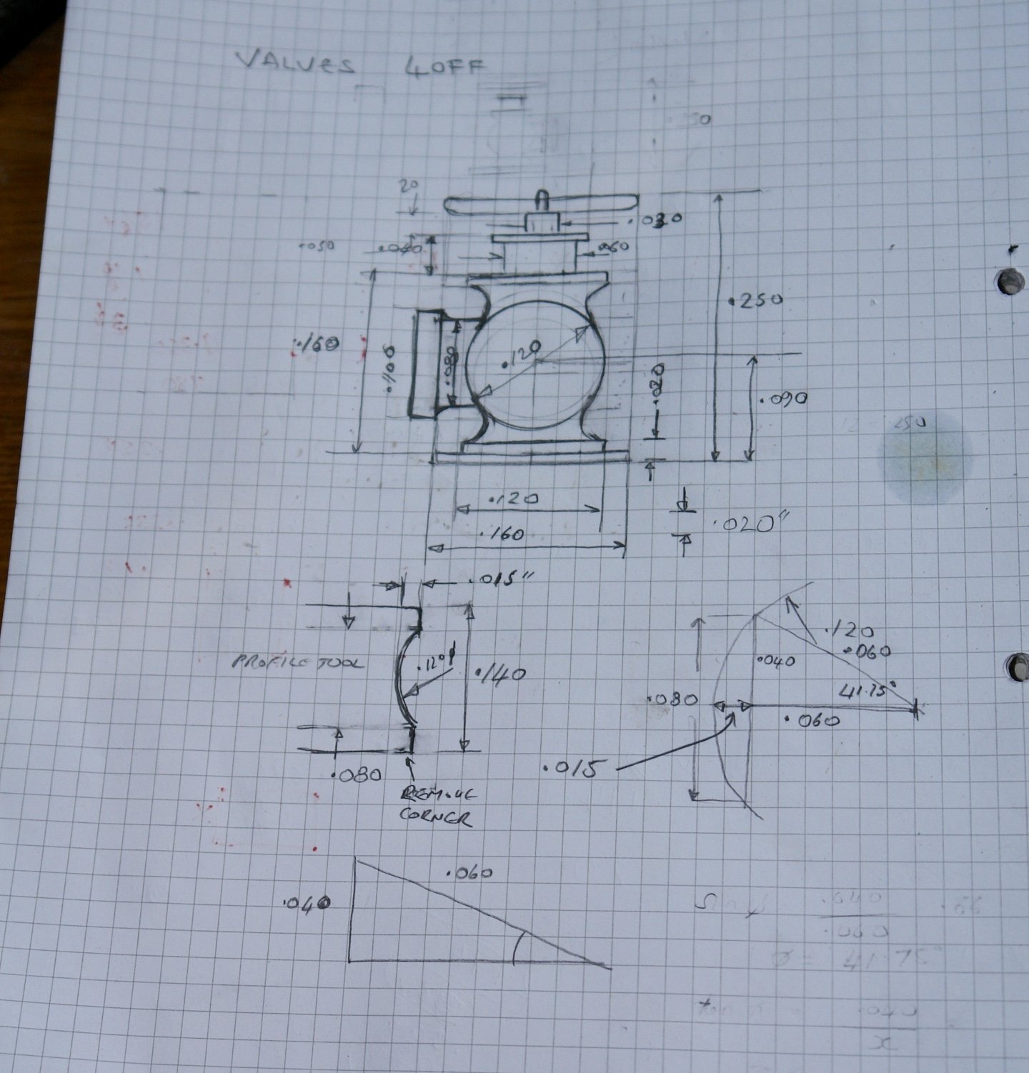
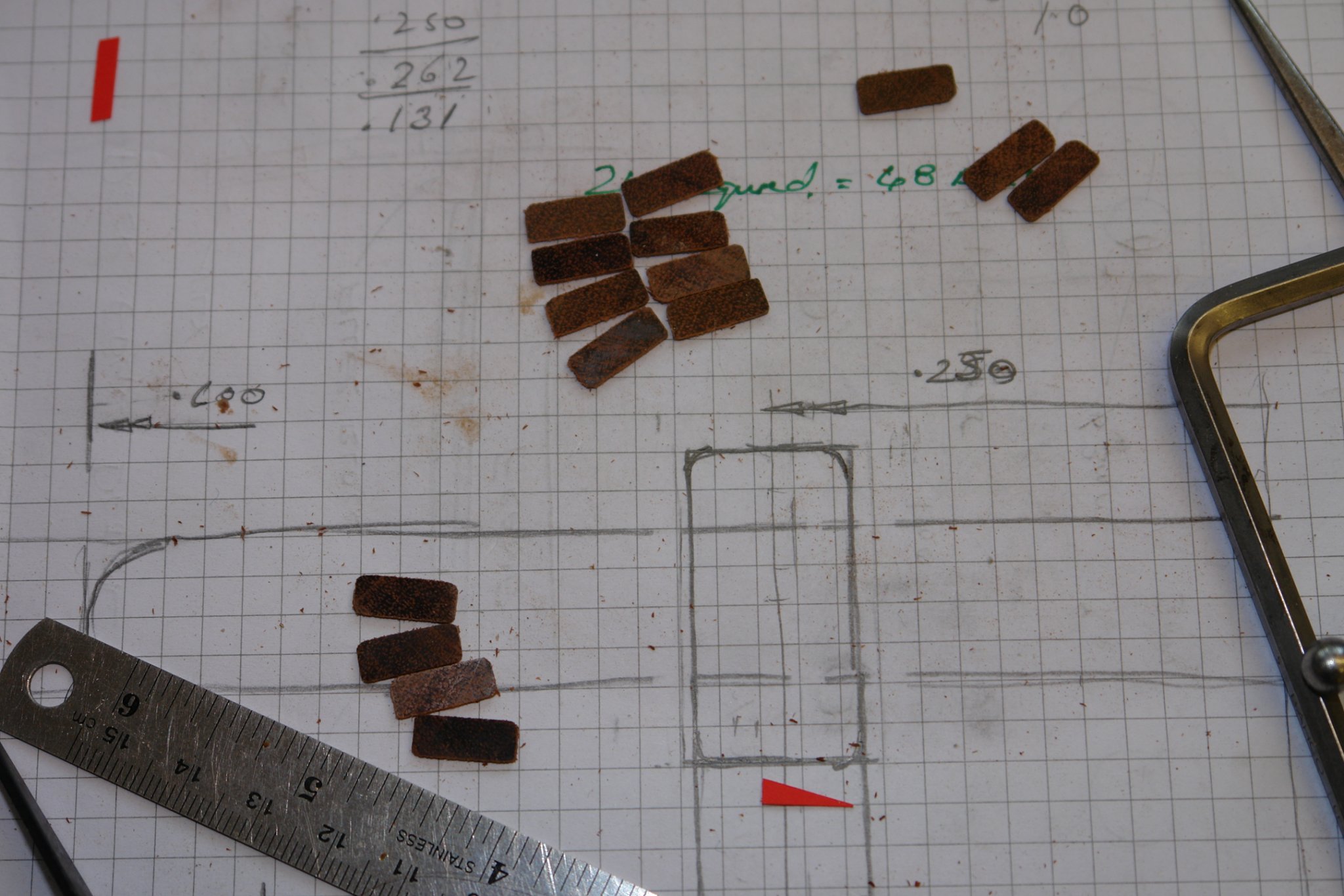
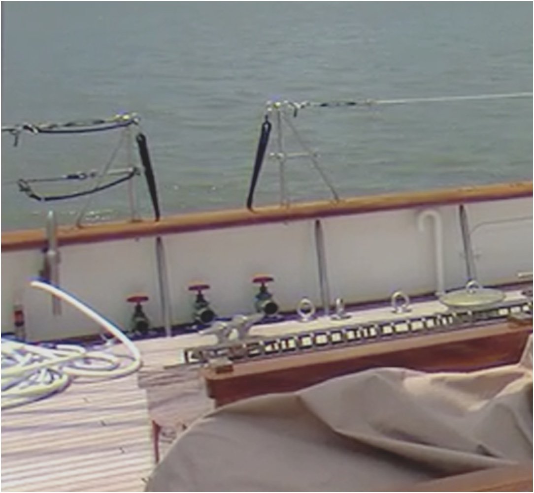
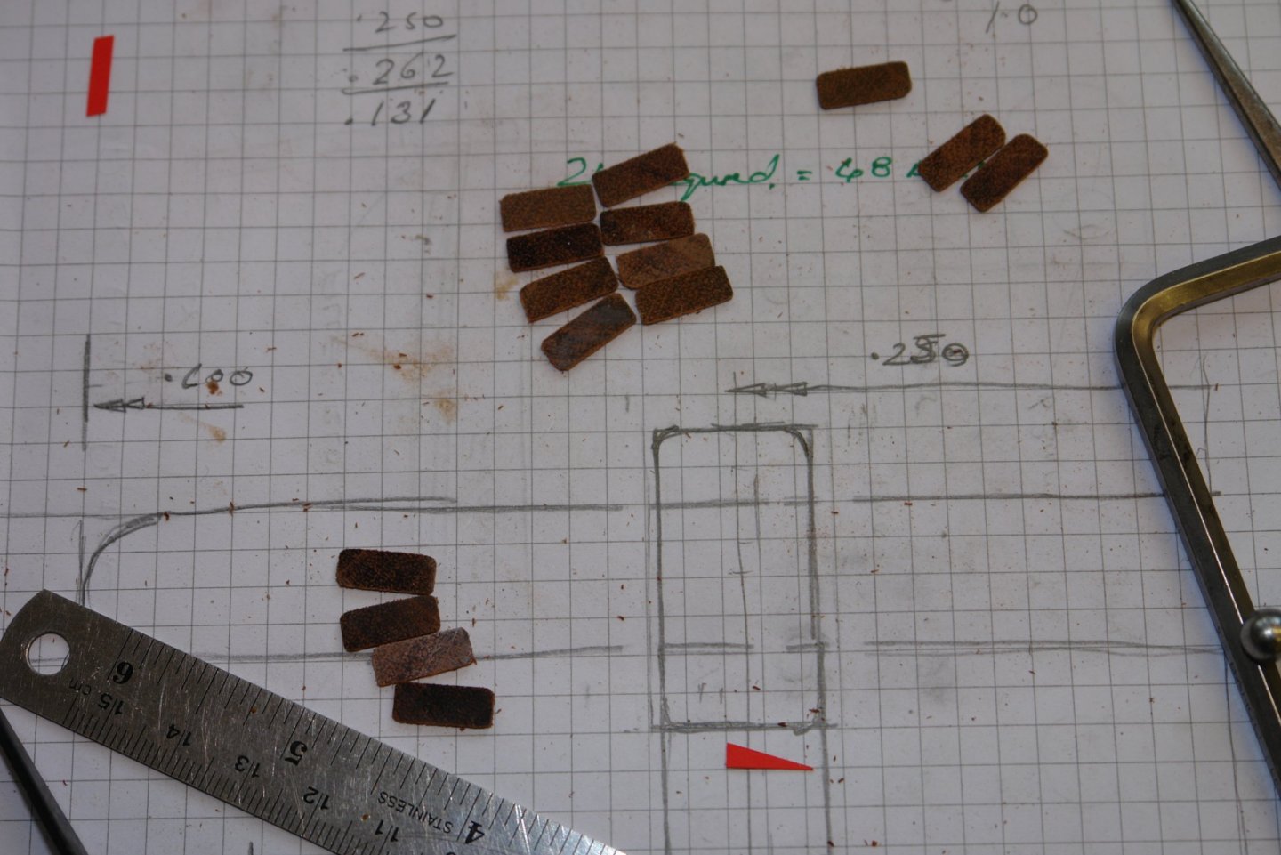
Keith, Hubert, G.L thank you for your supportive words. Eberhard - workshop closes for Christmas festivities one Christmas Eve. Plenty of time for a bit more metal work. Shipman - its good to know I am not alone. I find myself avoiding putting the capping rail on, basically because I think it is going to be tricky. Maybe I am over thinking it but in any case I decided to avoid the problem and start on the valves. From the photographs I have found 4 right-angled globe valves and one linear ball valve. Three globe valves are close together amidships and next to them in the ball valve attached to a hose - next photo. Not sure what the valves are for - one presumably is a water inlet but as to the other 3 your guess is a good as mine. I also need to make the vent pipe on the right hand side. The other globe valve is adjacent to the table and seats at the stern. By scaling the photos I came up with the following drawing. I also did a bit of geometry to define the shape of the profile tool that will form the globe. The profile tool sketch is below the valve. I find my large scale sketches deceive me into thinking that I can do more detail than is sometimes practical. The globe valves will be about 1/4" high so how much detail I get in will be interesting. My target is to get the valves and the vent made by Christmas Eve. Hopefully one more update to come before Santa arrives
-
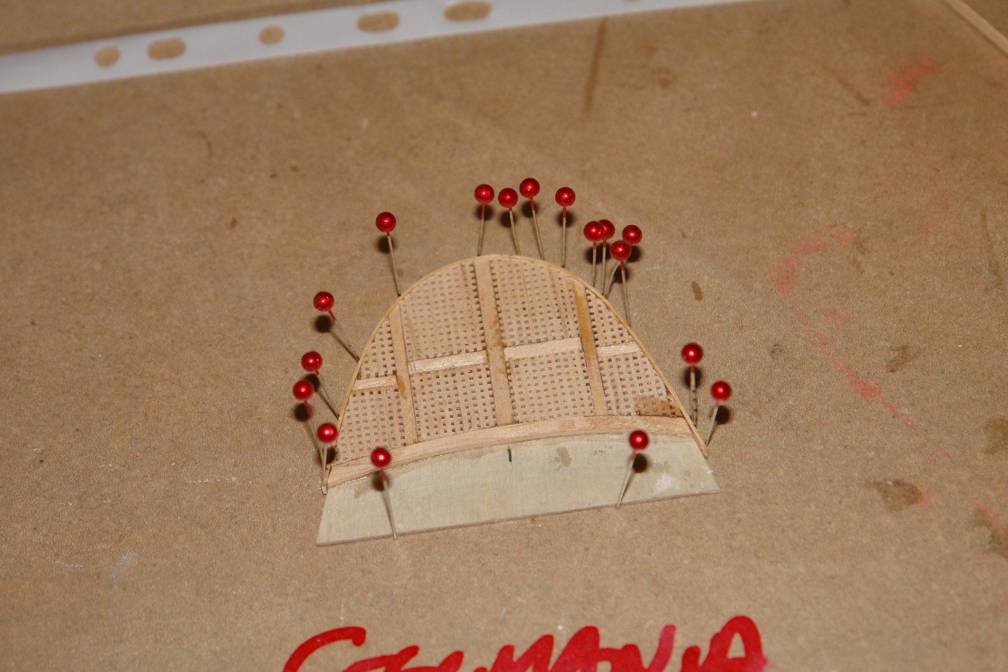
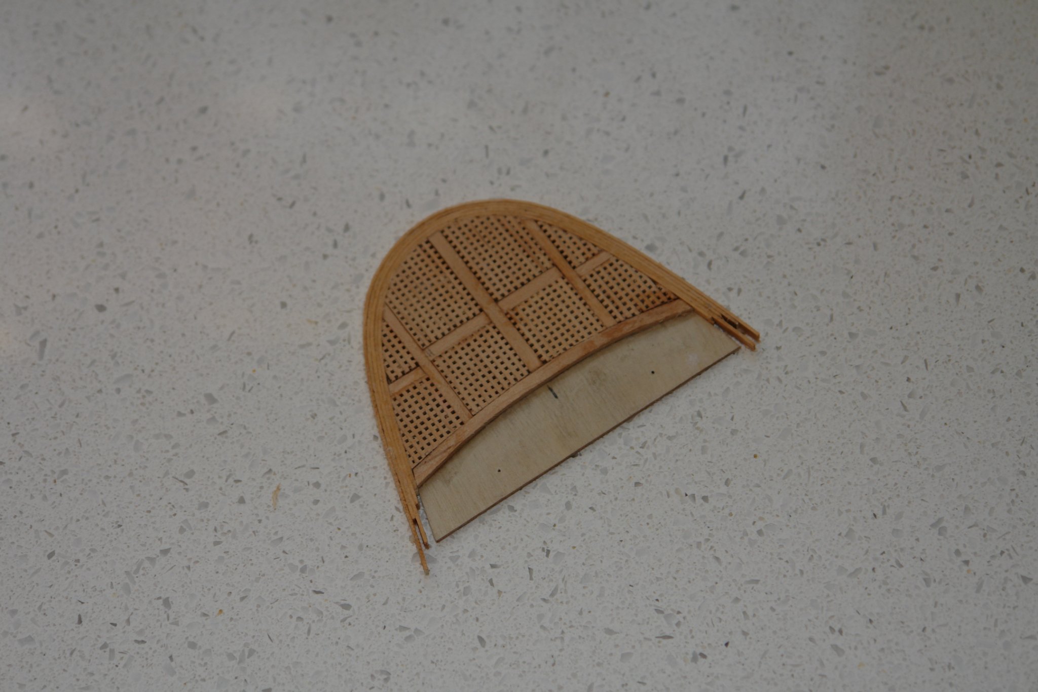
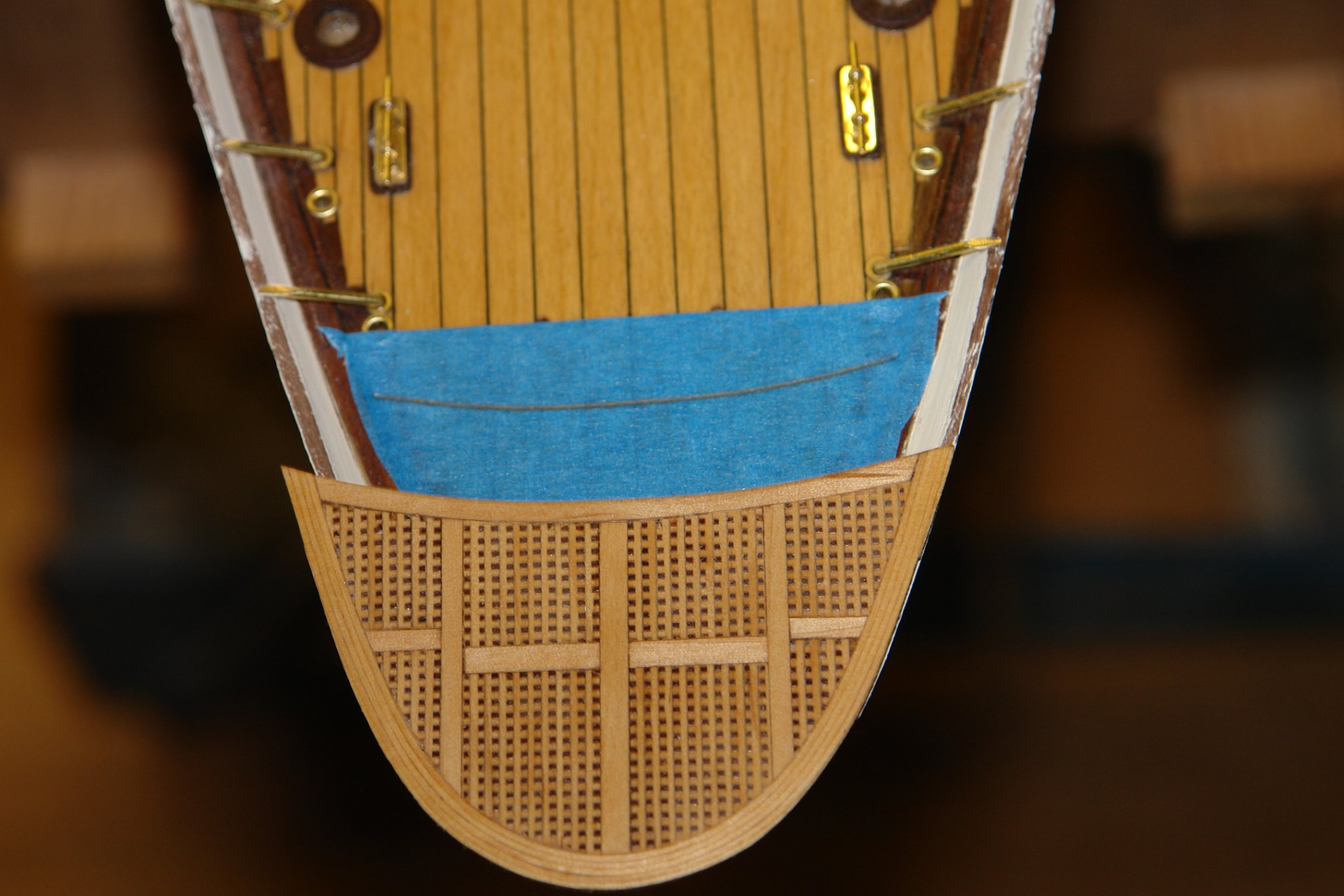
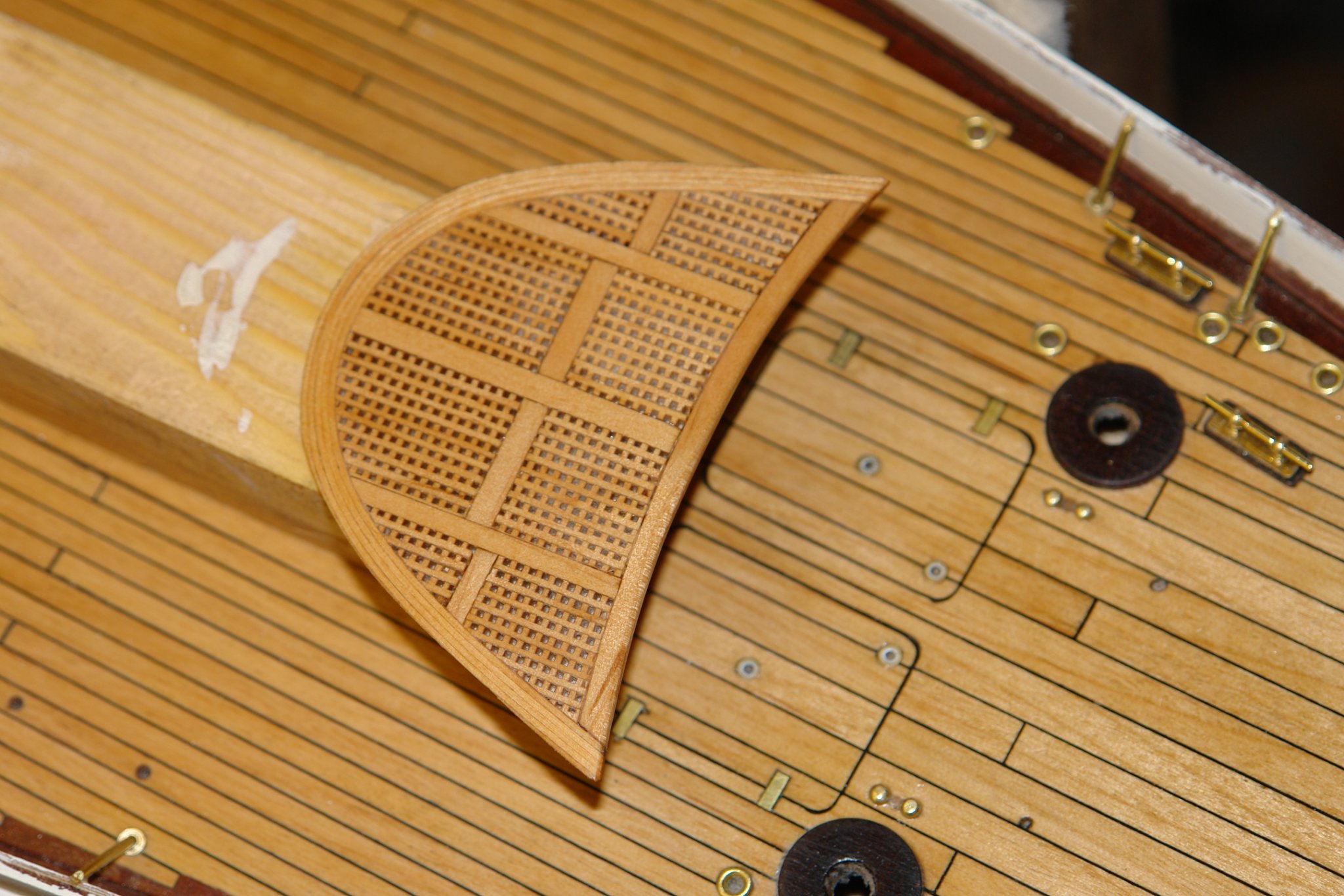
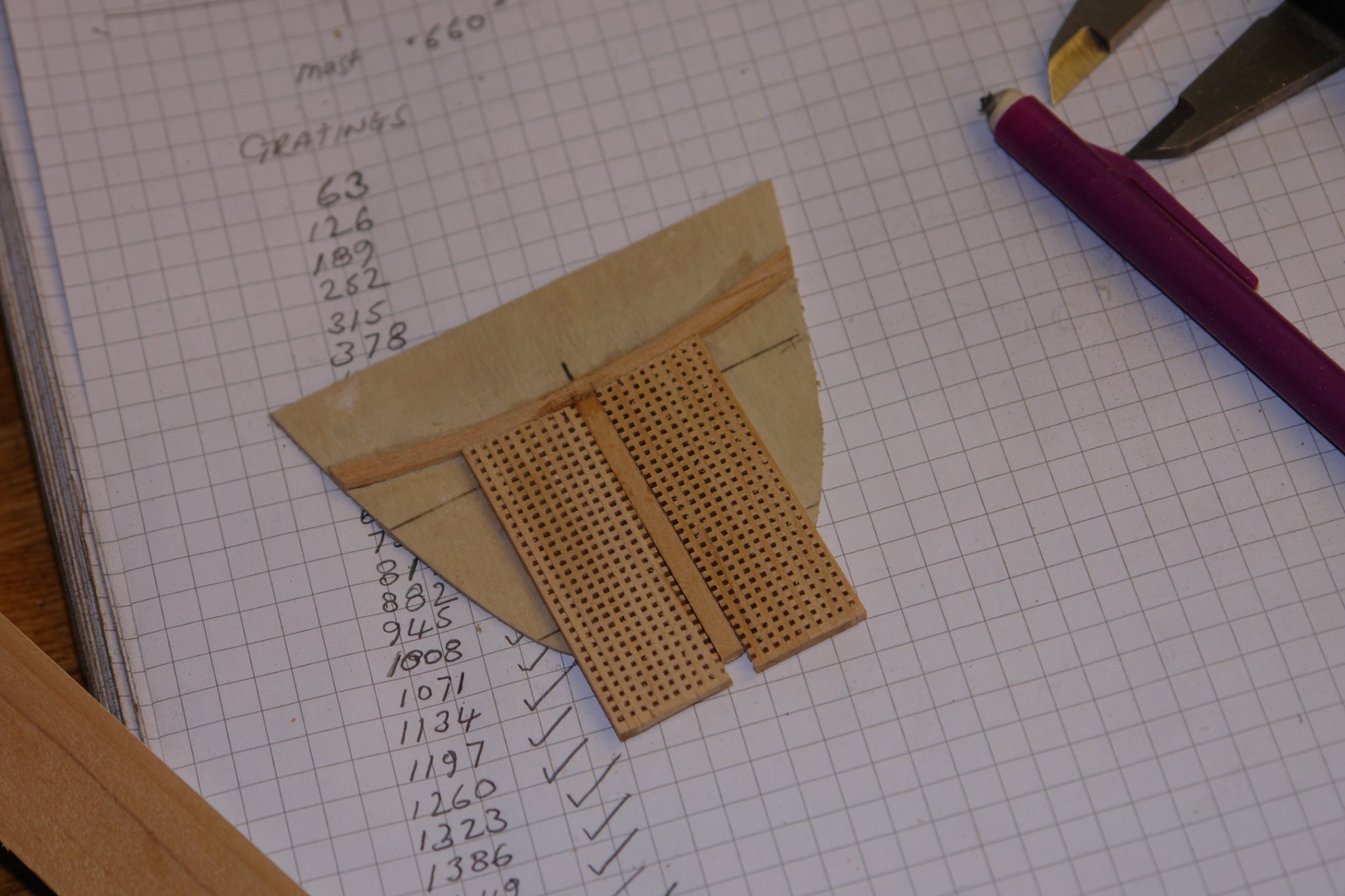
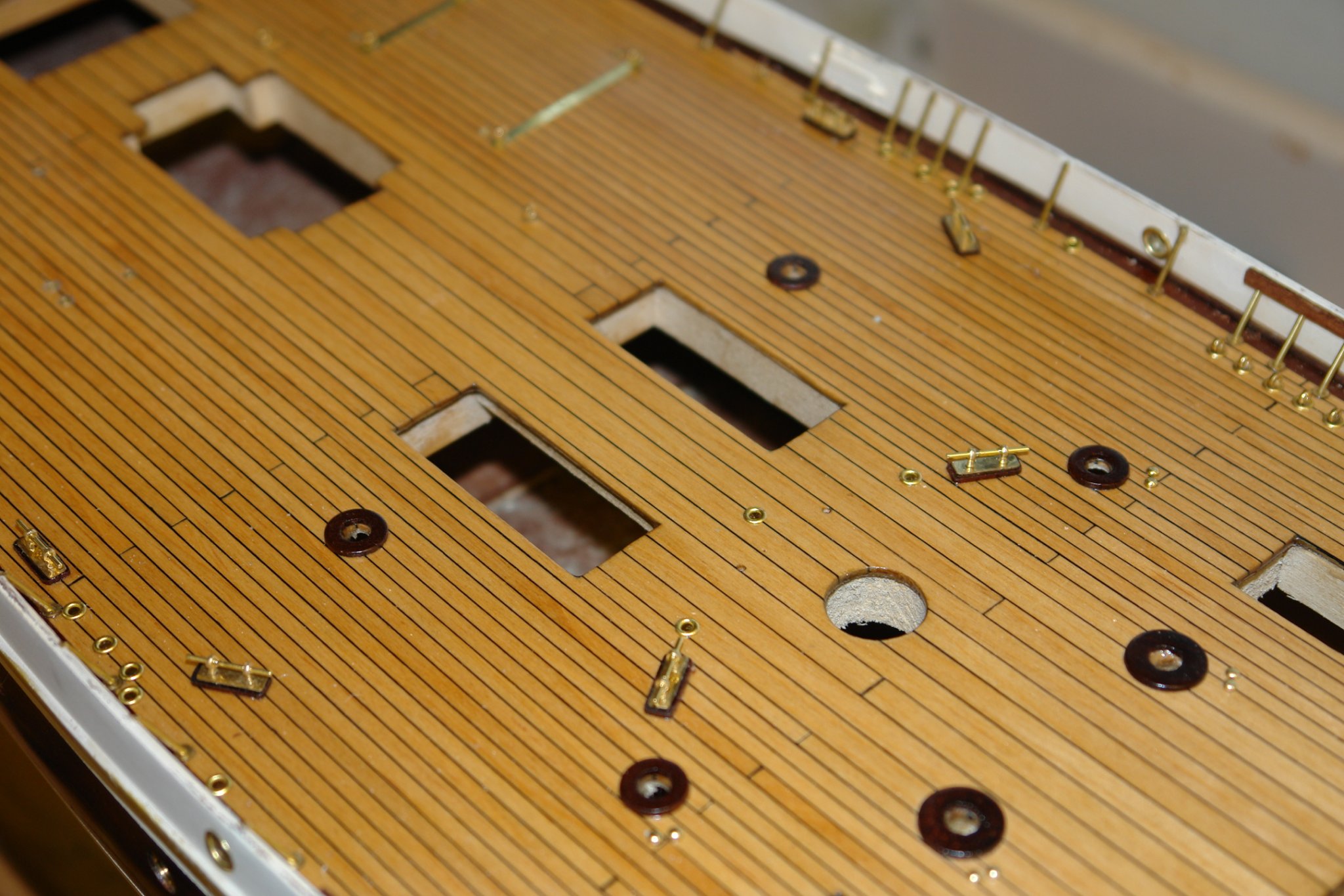
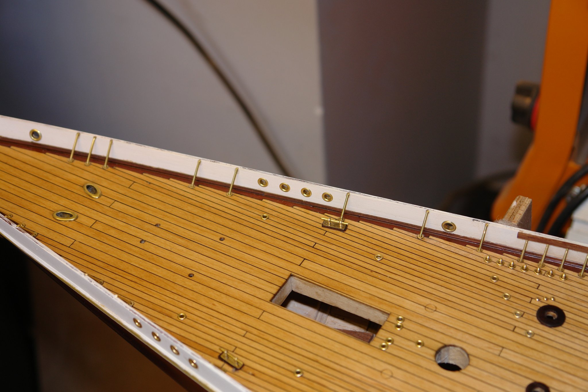
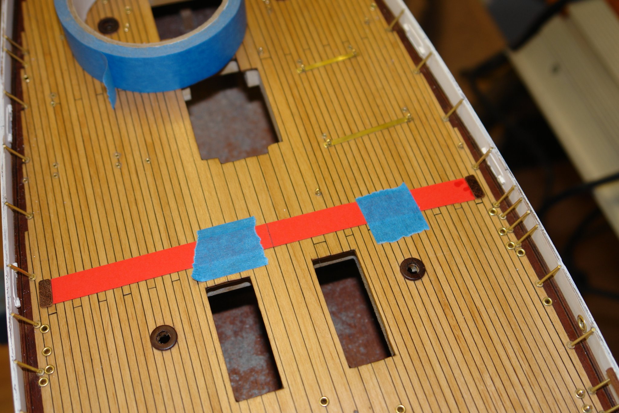
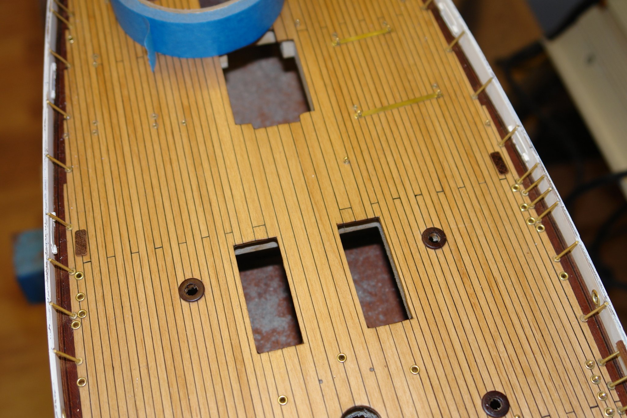
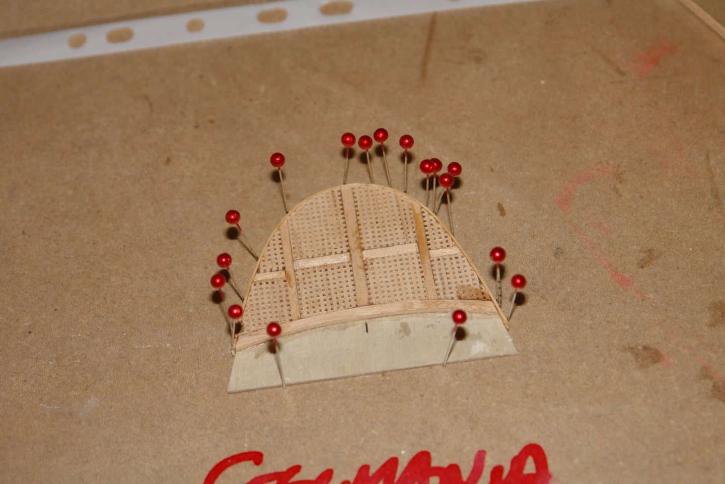
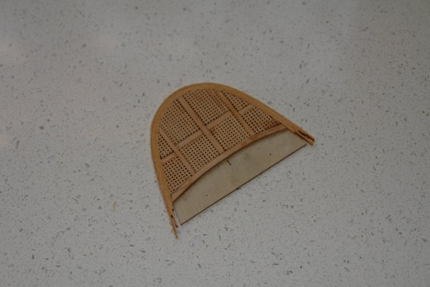
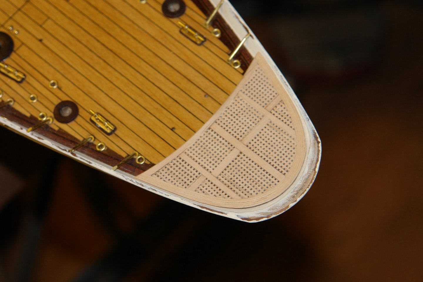
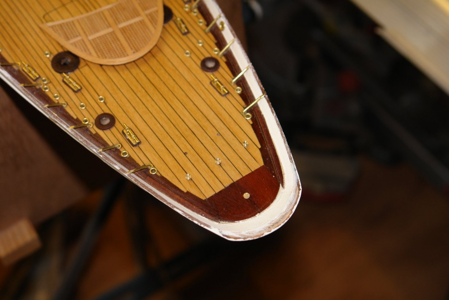
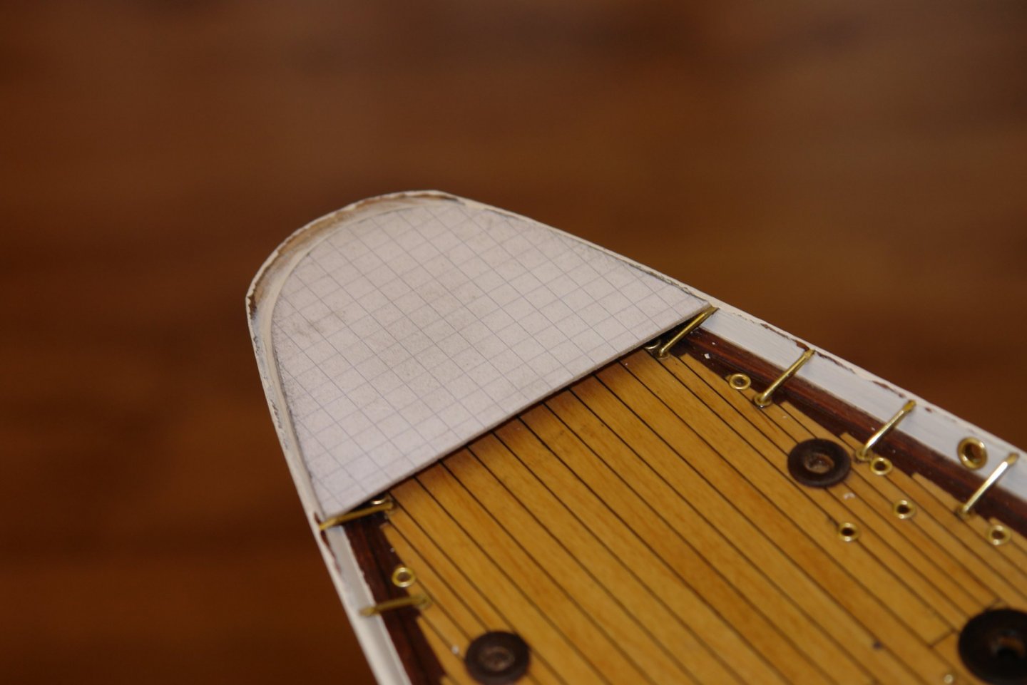
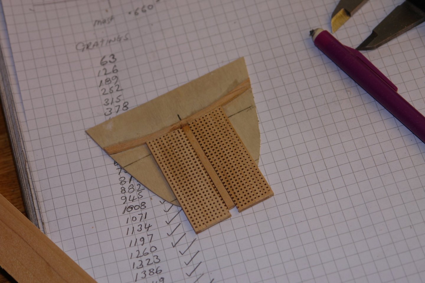
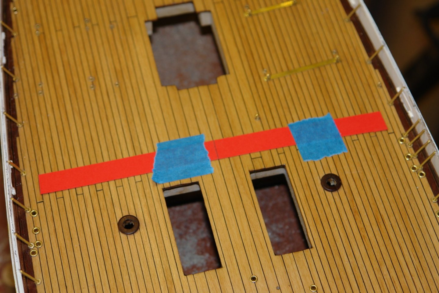
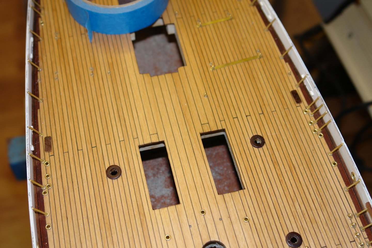
I continued making the raised deck at the stern. I was concerned at the lack of strength in the gratings so decided to build the deck on a 1/32 ply base board. I checked that the holes in the gratings were of insufficient size to make the ply visible. Shaping the gratings to size was a bit tricky given their fragility but with a sharp blade and jewellers saw I got it done. I had intended cutting the curved outer plank of the raised deck out of solid wood but I couldn't get the fit around the gratings tight enough. Laminating the edge proved to give a much more pleasing result. The strips laminated up to create the edge plank wire .025 thick. I needed 5 laminations. The edges needed to be shaped and chamfered to fit inside the bulwarks. I then finished the raised deck with a few coats of poly. The raised deck sits on small pedestals - I can only see the ones at the front edge of which there are 3. I used the raised deck to trace the front edge on a piece of masking tape and then used this line to position the pedestals. The pedestals were made with a spigot and holes were drilled in the main deck to take them. A 4th pedestal was placed under the raised deck for extra support.


-
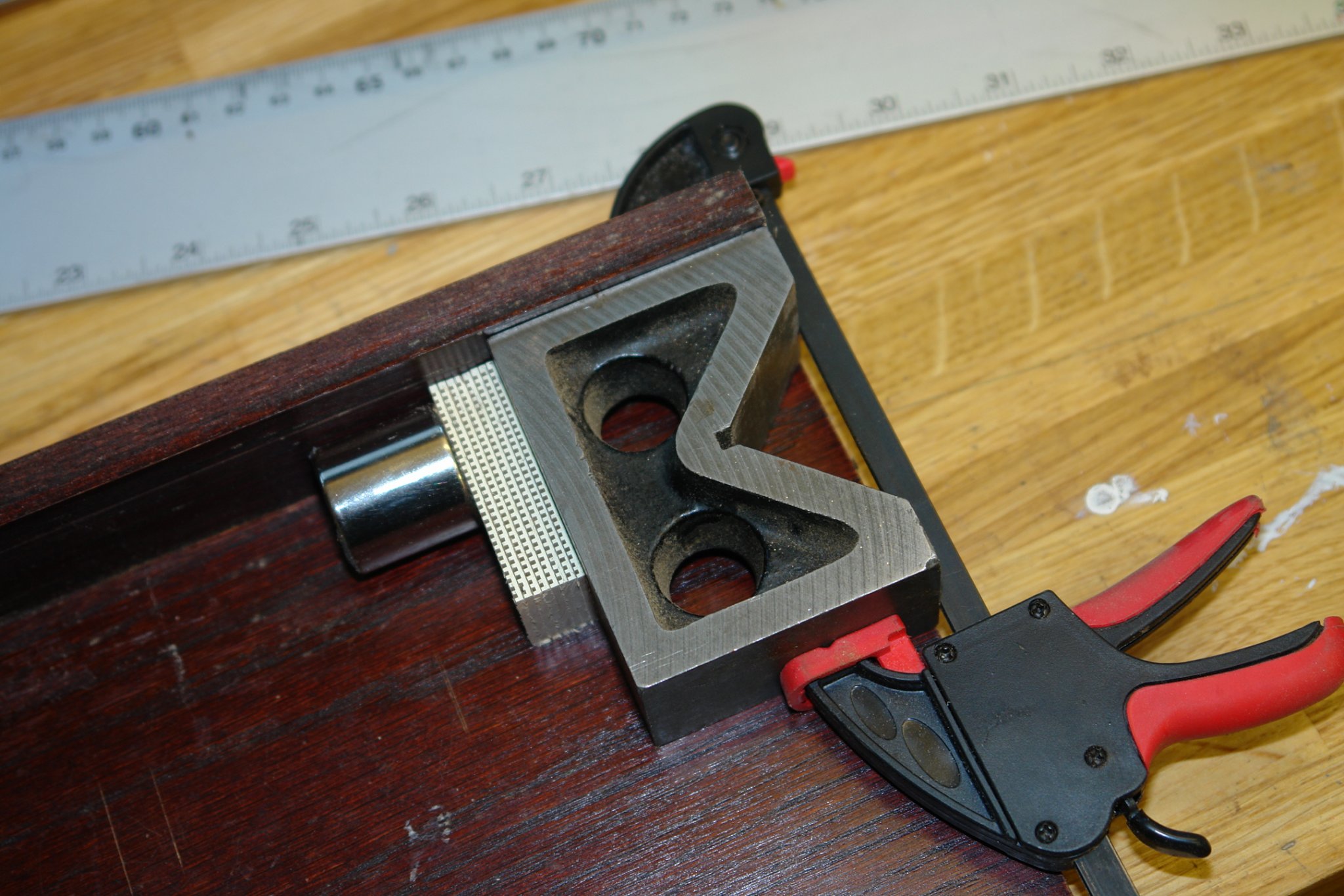
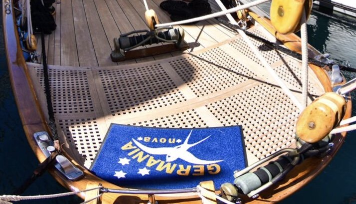
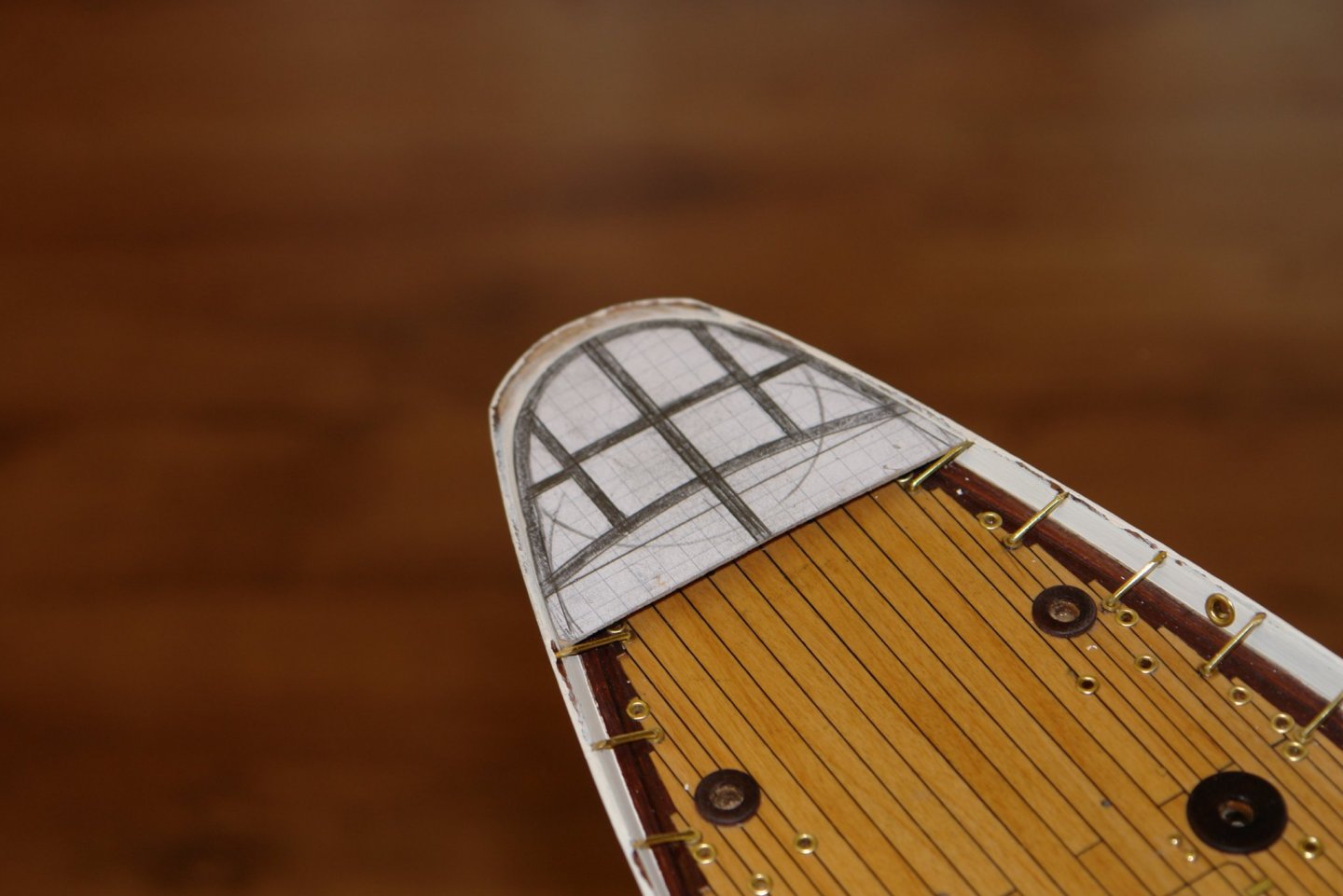
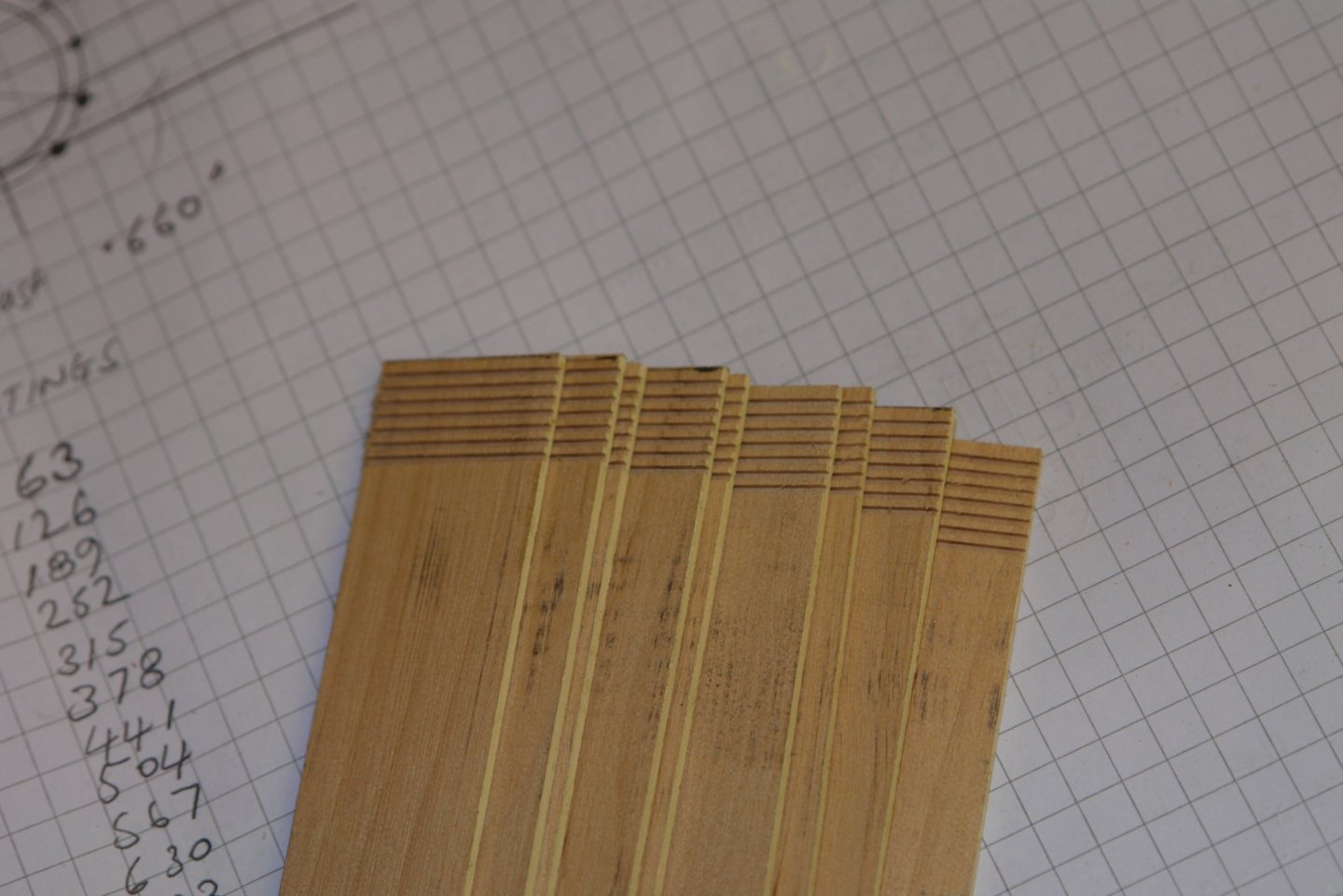
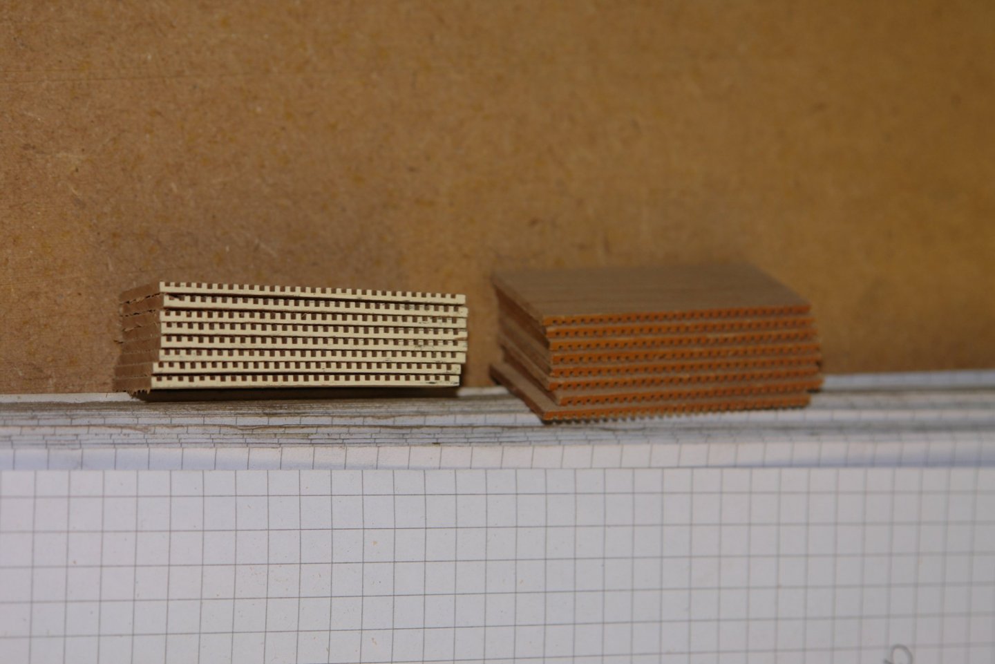
Thank you Mark. Over the past two days I have been making the raised grating deck at the stern. I made a template for the deck - basically paper glued on to 1/32" ply. This was shaped until the profile was a good fit to the inside profile of the bulwarks. On to this I drew the pattern for the solid planks which separate the gratings. Counting the grating holes on the photographs allowed me to get a good representation of the correct shape. As stated in an earlier post I decided to make the grating hole size slightly larger than on the original - equivalent to 1.1" square holes at full size. I worried that smaller gratings would be a bit too delicate. I used a 0.8mm (.031") slitting saw to cut the grating slots in timber .750" wide by .062" thick. The slots were machined .031" deep. The following photo shows the slotting at an early stage. The numbers down the side are the micrometer setting for the saw - you can see they are all .063" apart. After a number of hours I had 2 stacks. (One side of the wood had paint on one edge - hence the 2 colours). The stacks were then glued together with PVA glue. The set up probably needs a bit of explanation. The "V" block is clamped to board with a right-angled up-stand. The stacks are pushed against the up-stand and the "V" block. The silver thing on the left is a large rare earth magnet and this is providing the clamping force by attraction to the "V" block. Once the glue dried gratings were sliced off in preparation for cutting to size and shape.

-
Very nice work on the hurricane deck, all very impressive.
- 599 replies
-
- 4
-
-
- sidewheeler
- arabia
- (and 4 more)
-
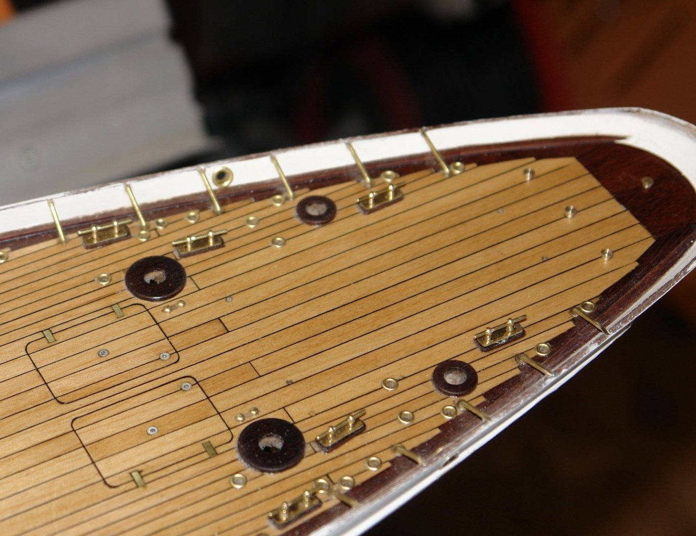
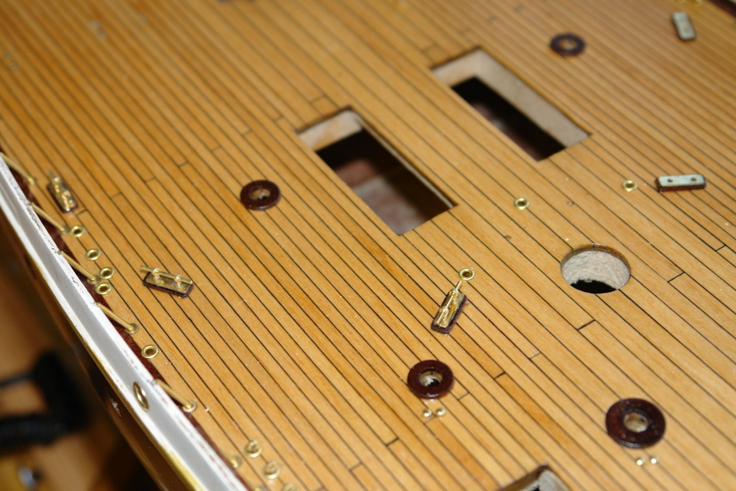
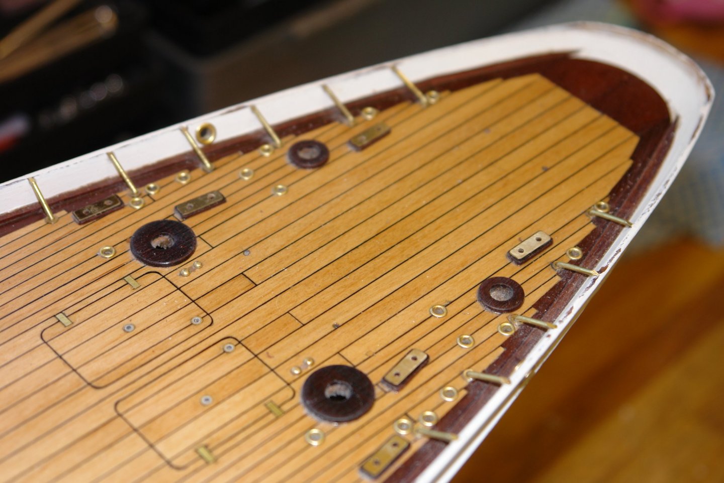
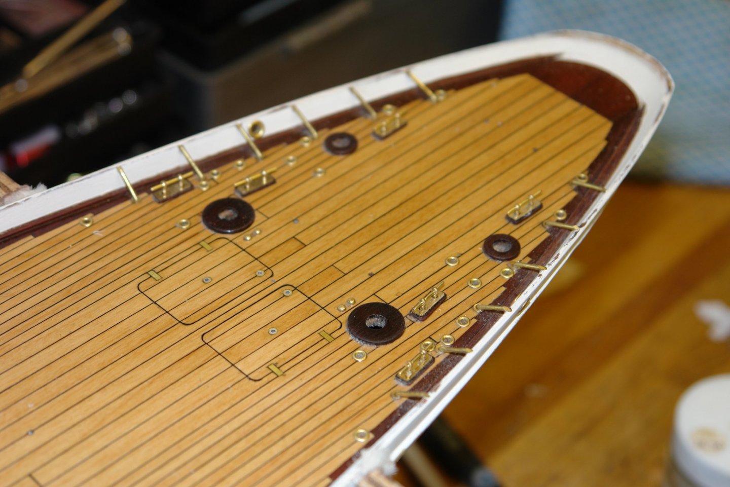
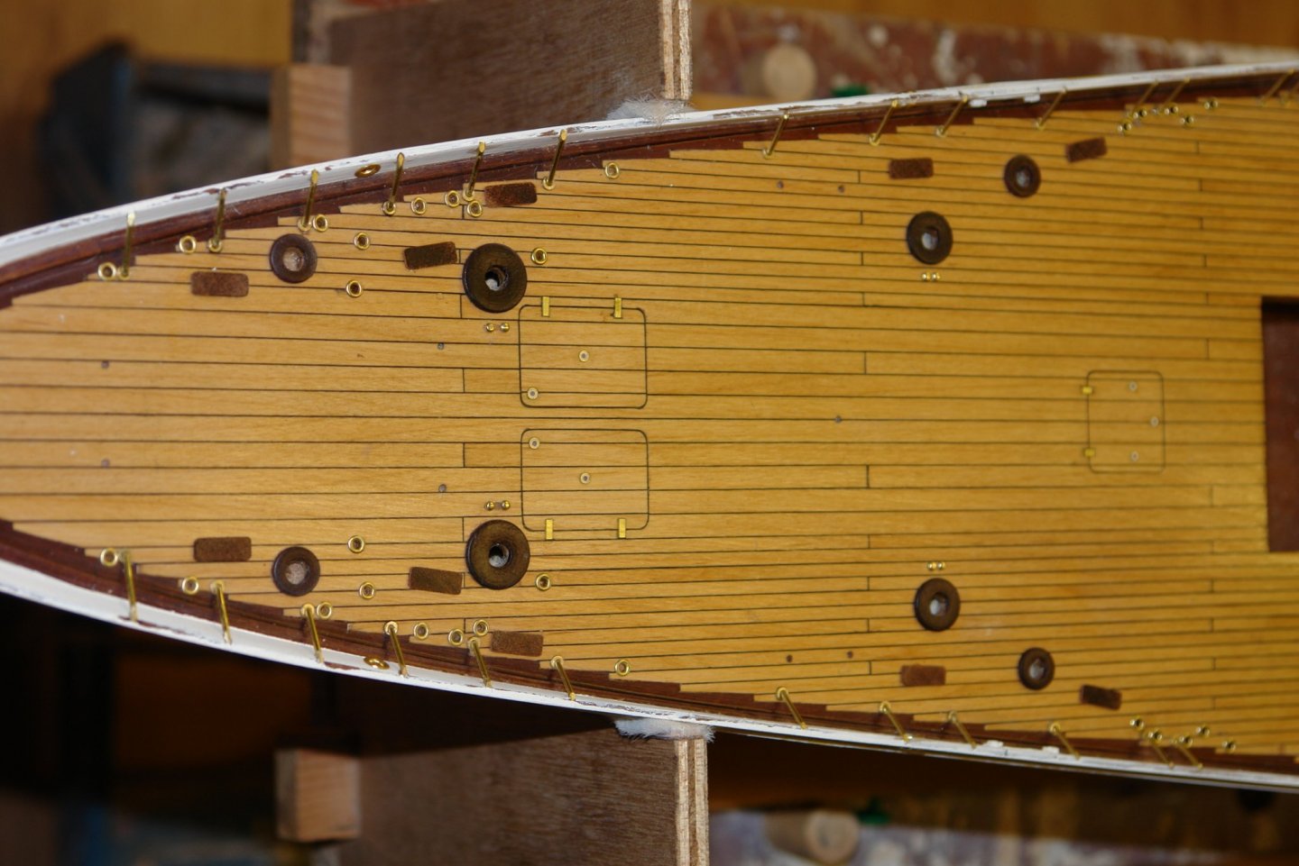
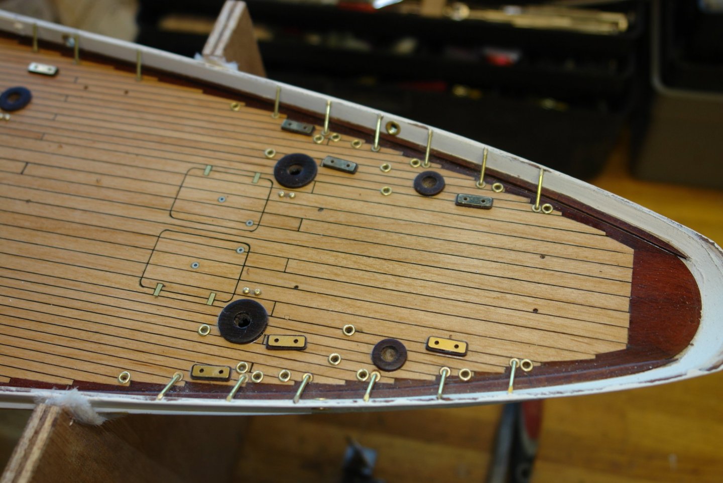
Pat, Gary, Michael - thank you for visiting and taking time to comment. Also thank you to everyone else who has visited and or liked my build. It seemed a bit warmer in the workshop over the weekend so I got on with finishing the cleats. As all the bits had been made previously this just involved assembly and careful glueing with CA. Not a lot to be said so I am just posting pictures of the result. The first image is significantly magnified (but it does make the deck planking look neat).


-
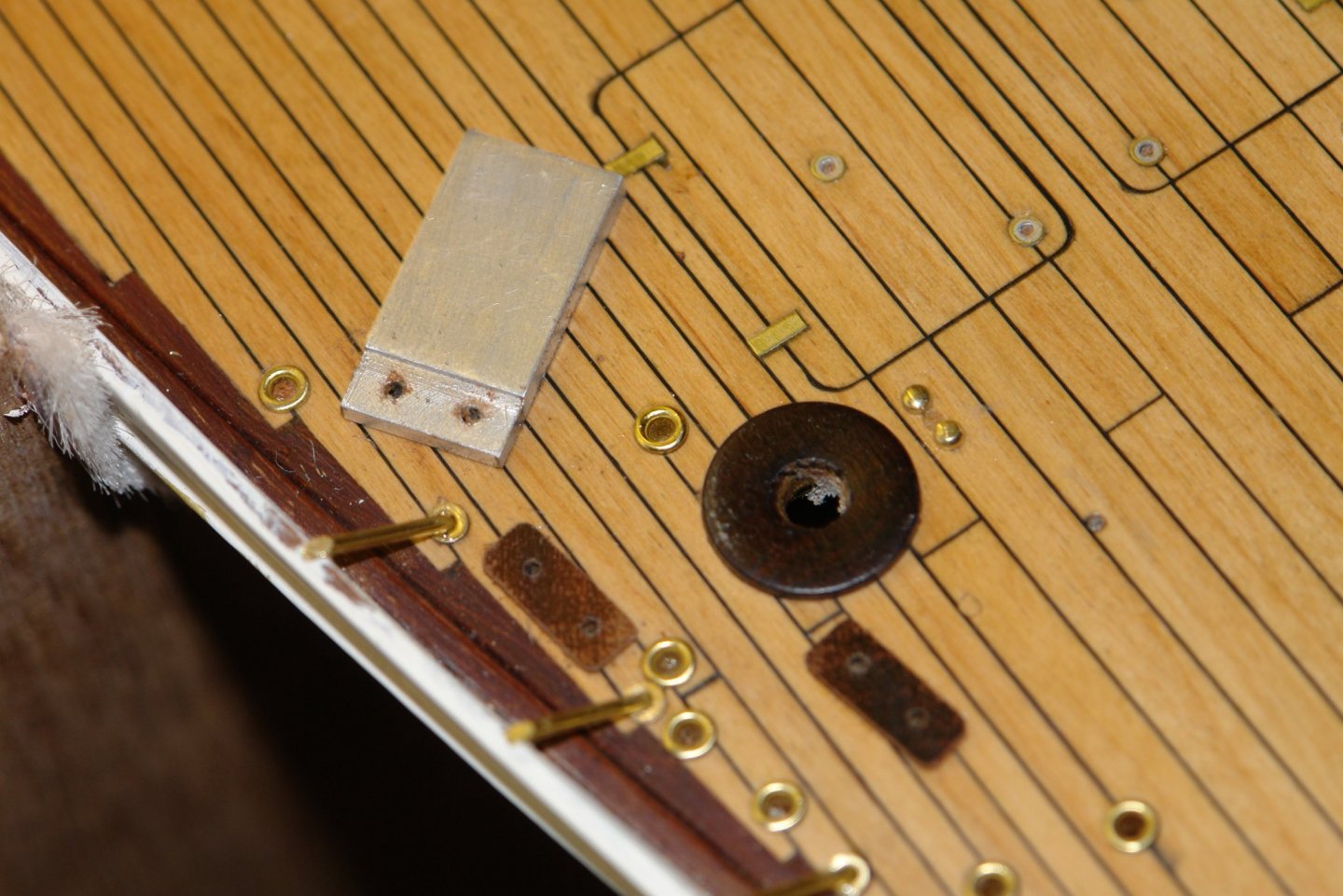
Almost at the end of the cleat saga:- The cleats sit on wooden plinths. Size .52"x.2"x.03". I shaped a piece of mahogany to .52"x.2" cross section and 3 inches long. The edges were sanded to a radius and then the plank was put on the table saw and .03" thick slices were cut off. I needed 18 but made a couple of spares (not all shown in photo) I cut card strips and stuck them on to the deck to fix the positions for the plinths. The plinths were glued in place with a dab of CA. I proceeded in this way until all plinths were in place. The drill jig was then used to drill the the plinths to take the cleat pedestals. At this stage all the plinths were painted with 4 coats of poly prior to the brass bases of the cleats being glued in place - once again with CA.


-
GL - Your casting of the keel was very interesting. Like Gary I would welcome a bit more detail, particularly around making the mould.
-
Gary - Lovely job on the gallows - but that is par for the course on this build. Once again very realistic paintwork.
-
Can i live without a BYRNES TABLE SAW
KeithAug replied to shihawk's topic in Modeling tools and Workshop Equipment
Yes that's how I did it until I got frustrated with having to use 2 hands. Now it is easier and quicker which is important when you change blades frequently as I do. I do a lot of my work with fine toothed slitting saws and they are much more difficult to jamb than a TCT saw. -
Can i live without a BYRNES TABLE SAW
KeithAug replied to shihawk's topic in Modeling tools and Workshop Equipment
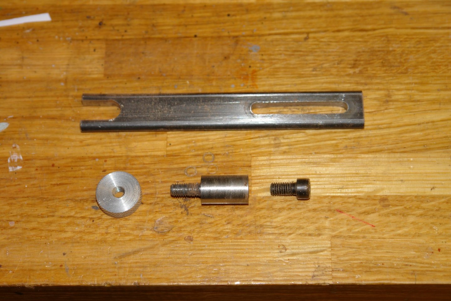
No idea ---- If I understand, you mean use a spanner instead of the bar I made. The issue is that the bar has to be slotted and slotting out the shaft of a chrome vanadium spanner would have been more difficult than machining up a piece of mild steel bar. -
Can i live without a BYRNES TABLE SAW
KeithAug replied to shihawk's topic in Modeling tools and Workshop Equipment
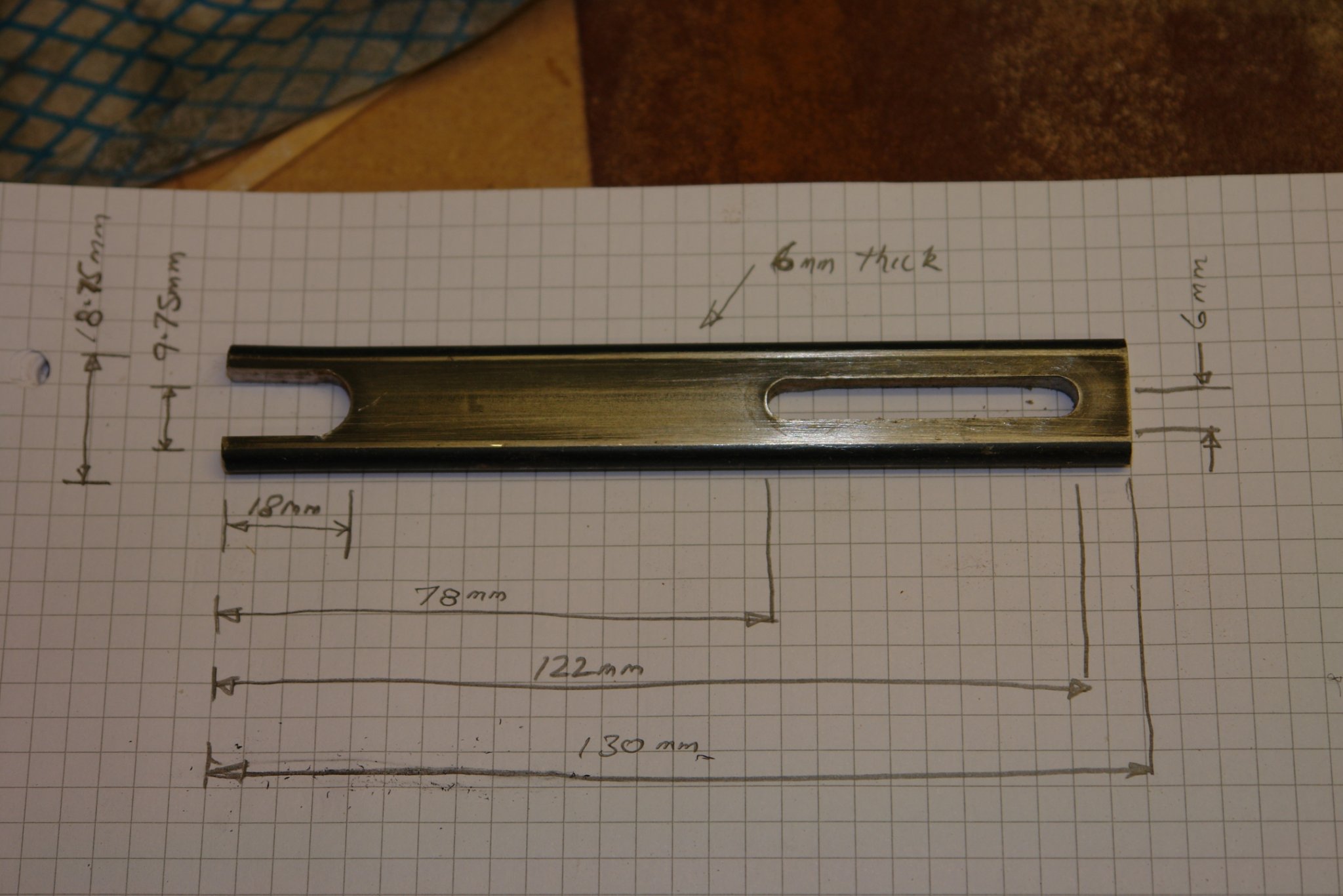
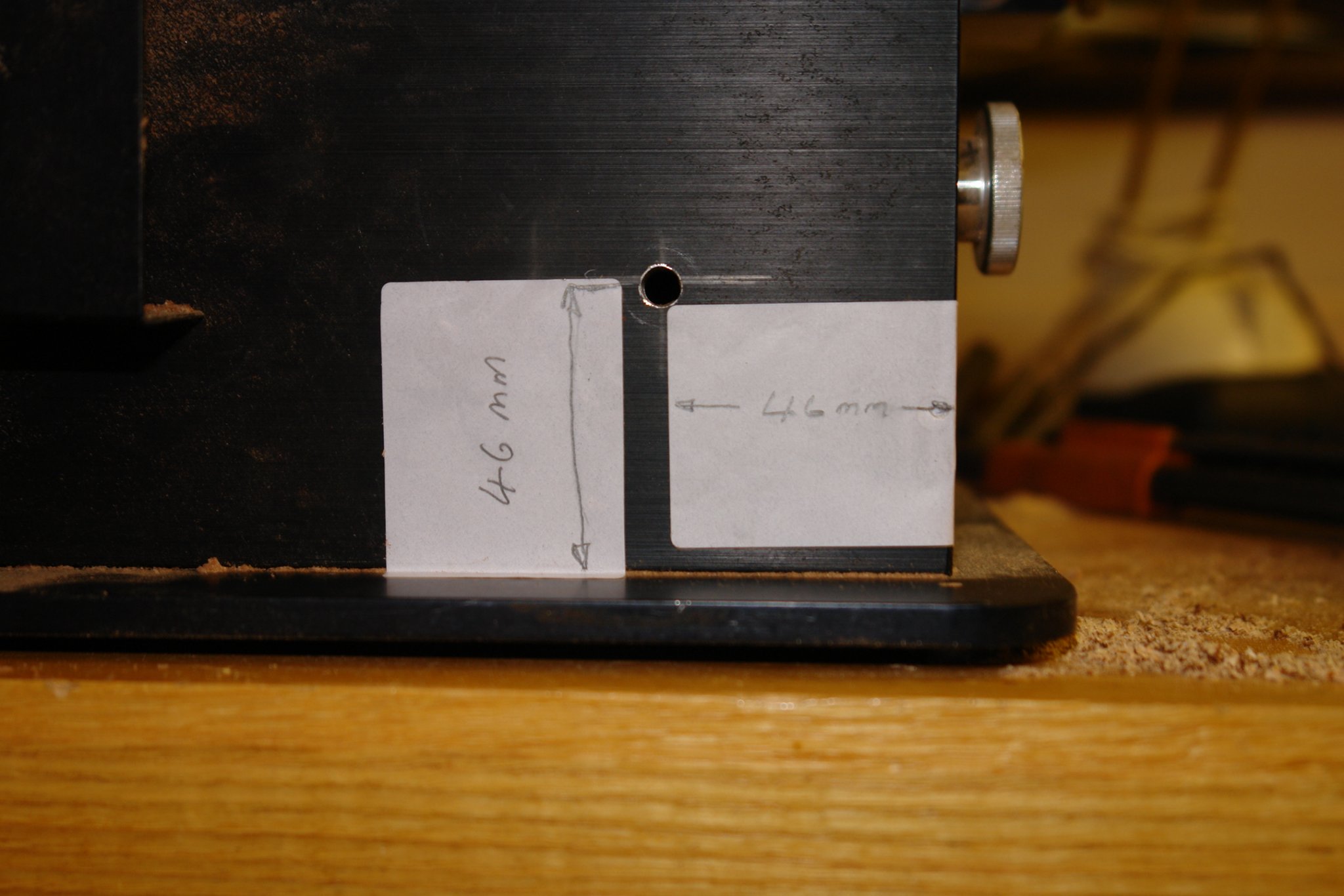
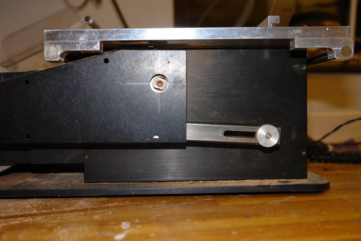
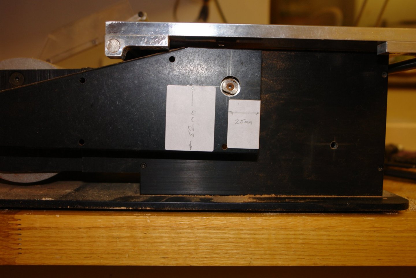
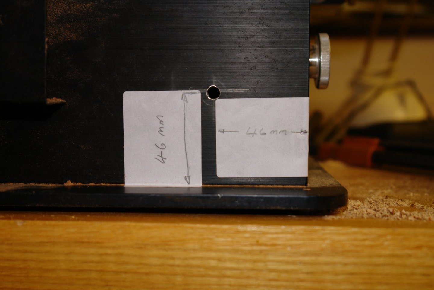
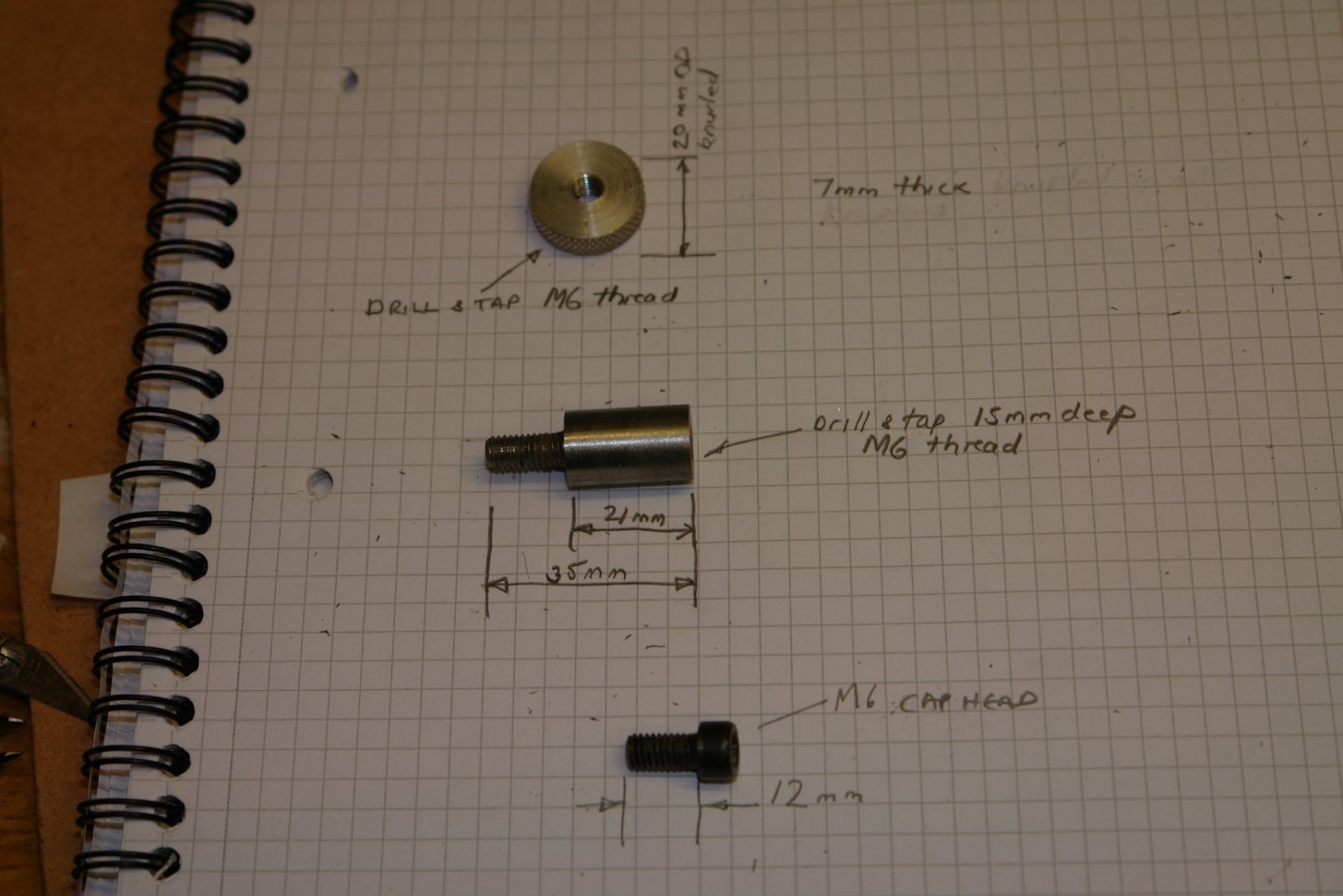
I had a request for details of my Byrnes Saw shaft lock (to assist with blade changing). I have posted the details here to make them generally available. Photo of shaft lock (in parked position):- Shaft lock components:- Sizing Information:- The large diameter of pivot arm (2nd item below) is 12mm. The viewing window for the saw shaft is 20mm diameter - cut in the belt cover with a step drill. The belt cover was removed to cut this hole. The hole for the pivot arm was 6mm diameter.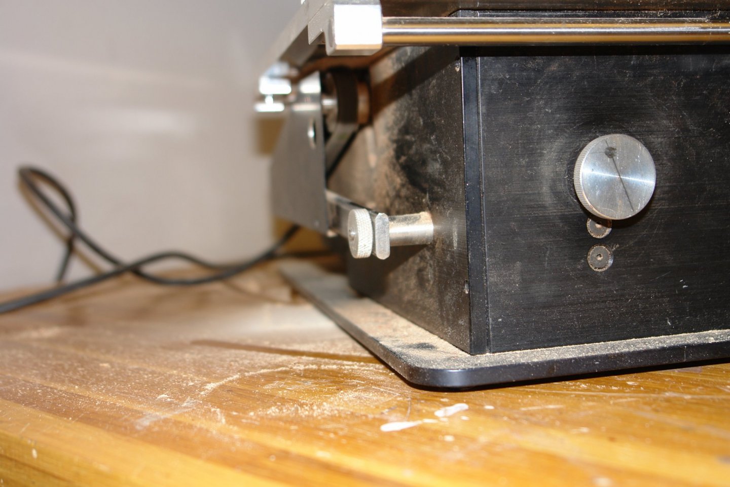

-
I thought moggies was a British name for cats - obviously I was wrong. I looked up the definition:- a cat, typically one that does not have a pedigree or is otherwise unremarkable. This doesn't seem to be quite the sort of cat Paul has.