KeithAug
-
Posts
3,986 -
Joined
-
Last visited
Content Type
Profiles
Forums
Gallery
Events
Everything posted by KeithAug
-

Can i live without a BYRNES TABLE SAW
KeithAug replied to shihawk's topic in Modeling tools and Workshop Equipment
Yes that's how I did it until I got frustrated with having to use 2 hands. Now it is easier and quicker which is important when you change blades frequently as I do. I do a lot of my work with fine toothed slitting saws and they are much more difficult to jamb than a TCT saw. -
Can i live without a BYRNES TABLE SAW
KeithAug replied to shihawk's topic in Modeling tools and Workshop Equipment
No idea ---- If I understand, you mean use a spanner instead of the bar I made. The issue is that the bar has to be slotted and slotting out the shaft of a chrome vanadium spanner would have been more difficult than machining up a piece of mild steel bar. -
Can i live without a BYRNES TABLE SAW
KeithAug replied to shihawk's topic in Modeling tools and Workshop Equipment
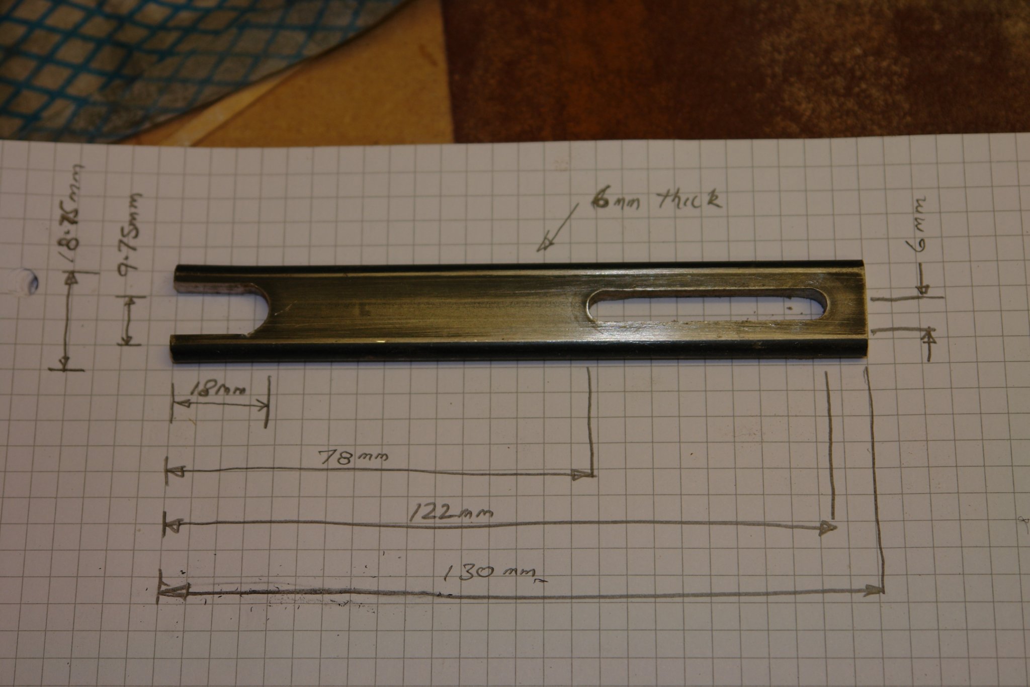
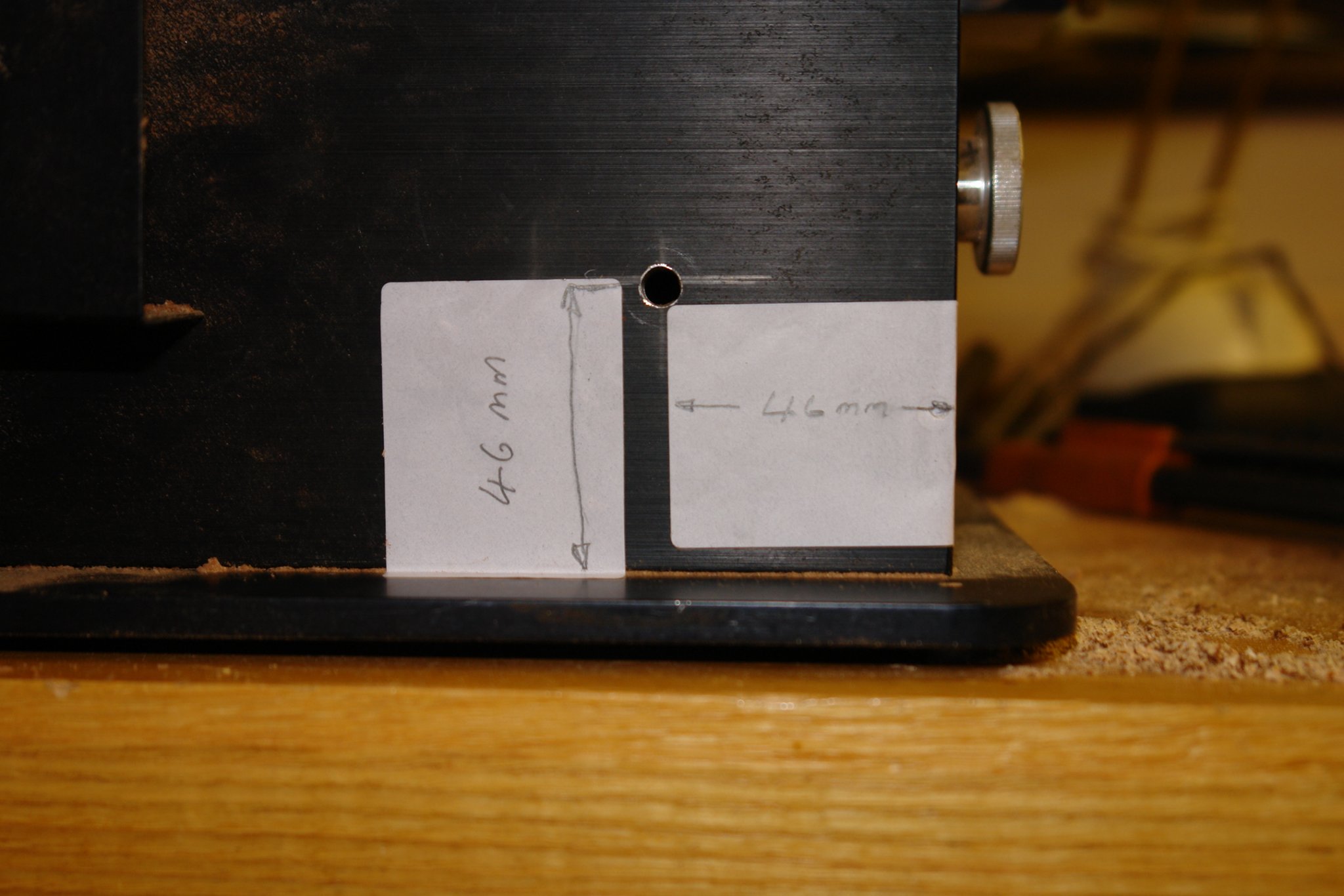
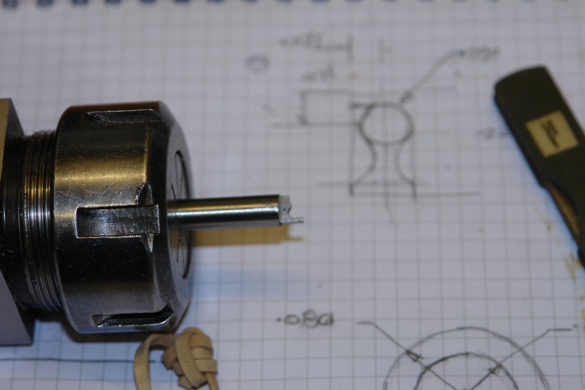
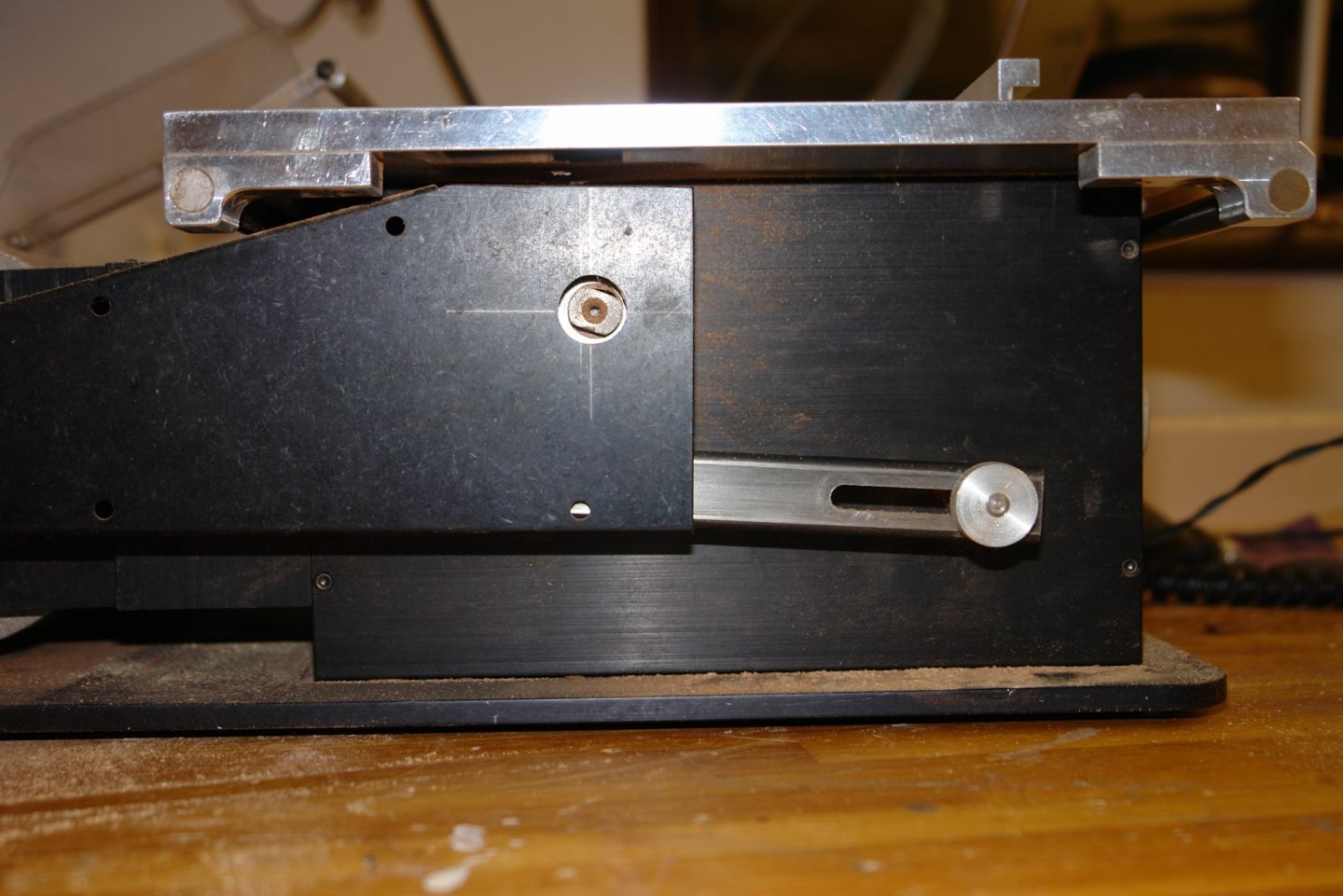
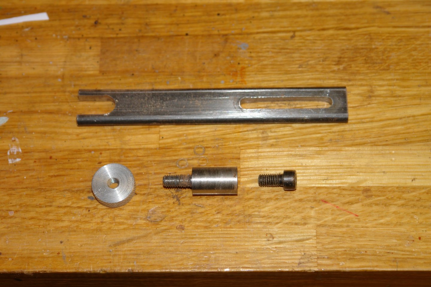
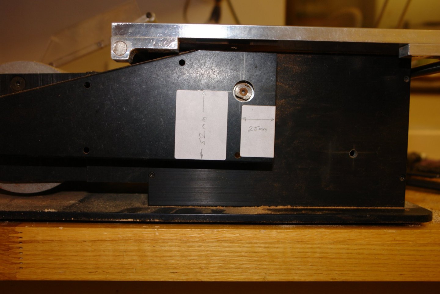
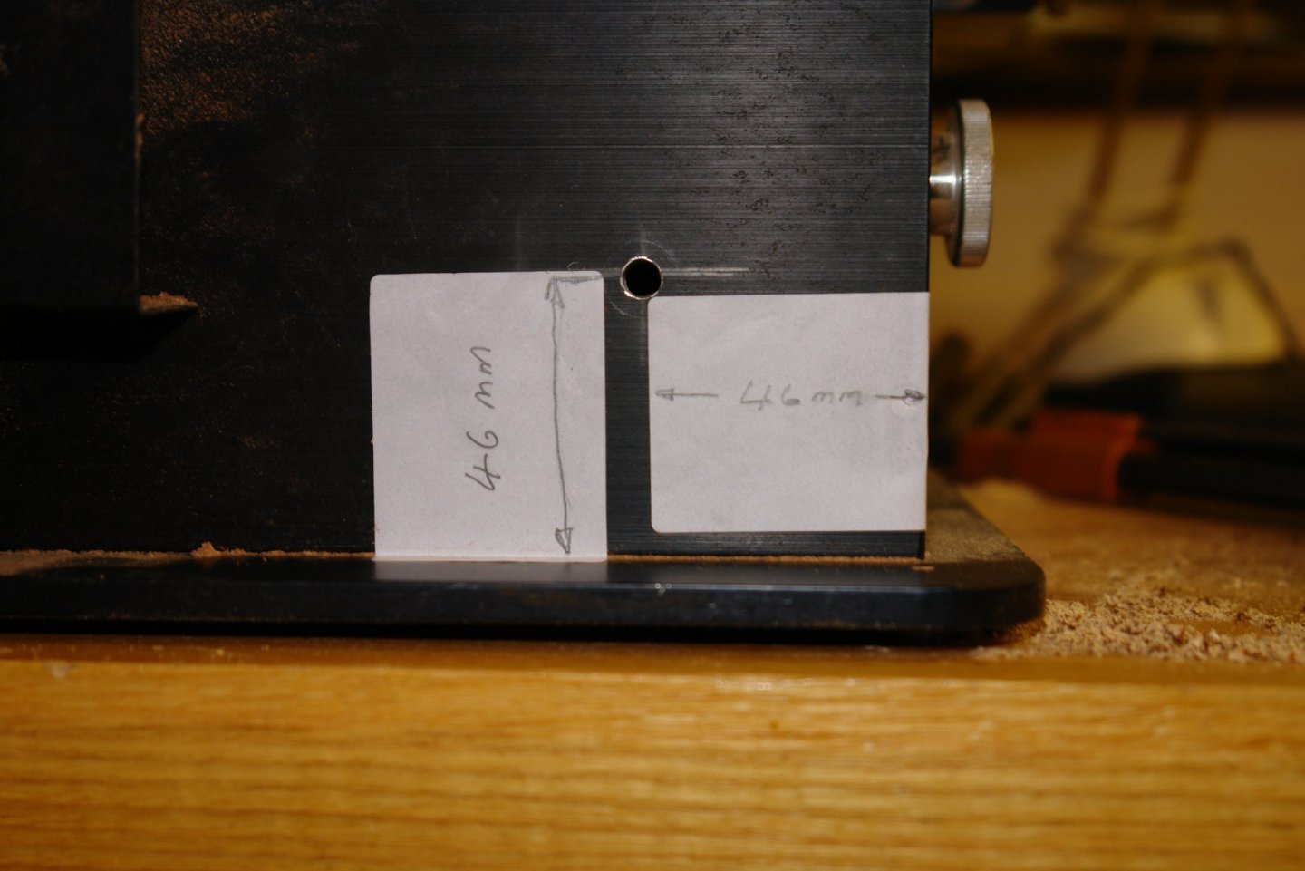
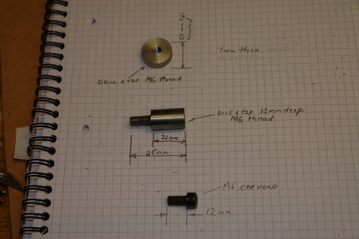
I had a request for details of my Byrnes Saw shaft lock (to assist with blade changing). I have posted the details here to make them generally available. Photo of shaft lock (in parked position):- Shaft lock components:- Sizing Information:- The large diameter of pivot arm (2nd item below) is 12mm. The viewing window for the saw shaft is 20mm diameter - cut in the belt cover with a step drill. The belt cover was removed to cut this hole. The hole for the pivot arm was 6mm diameter.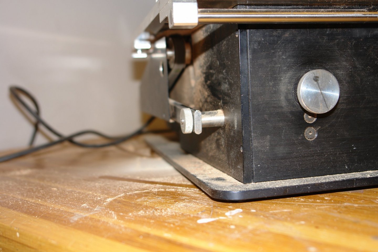

-
I thought moggies was a British name for cats - obviously I was wrong. I looked up the definition:- a cat, typically one that does not have a pedigree or is otherwise unremarkable. This doesn't seem to be quite the sort of cat Paul has.
-
Dan. Towards the end of the cut when only a very thin web remains the cutter tends to push rather than cut and the deck plate starts to lift away from the top of the saw. With care you can stop the cut just before it parts company and then tear off the remaining web which by this stage is only a few thousandths thick.. Thank you for the compliment. Eberhard - thank you for the tip. I hadn't come across them but found them under the name of "Cup Burr". I think I will add some to my Santa list.
-
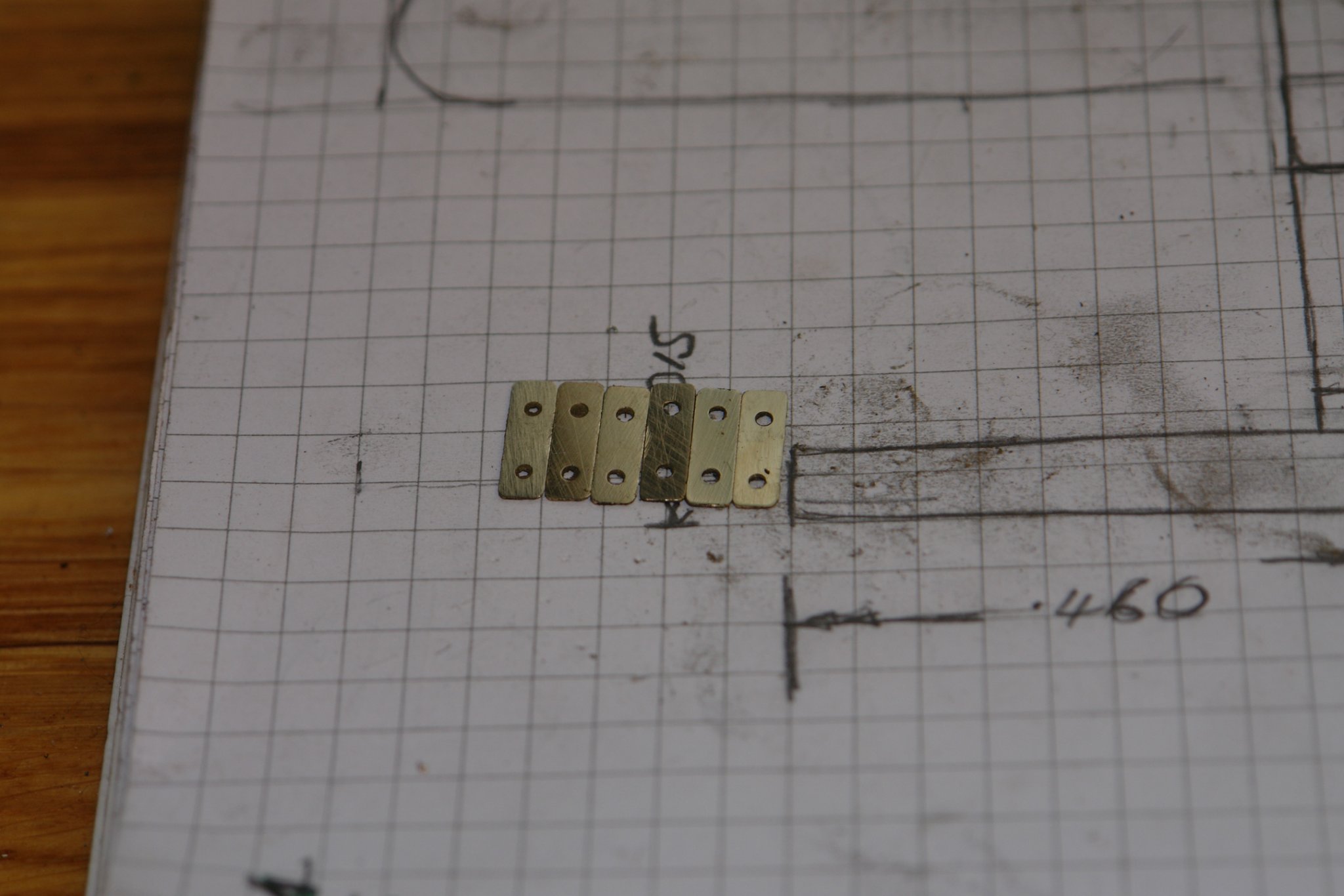
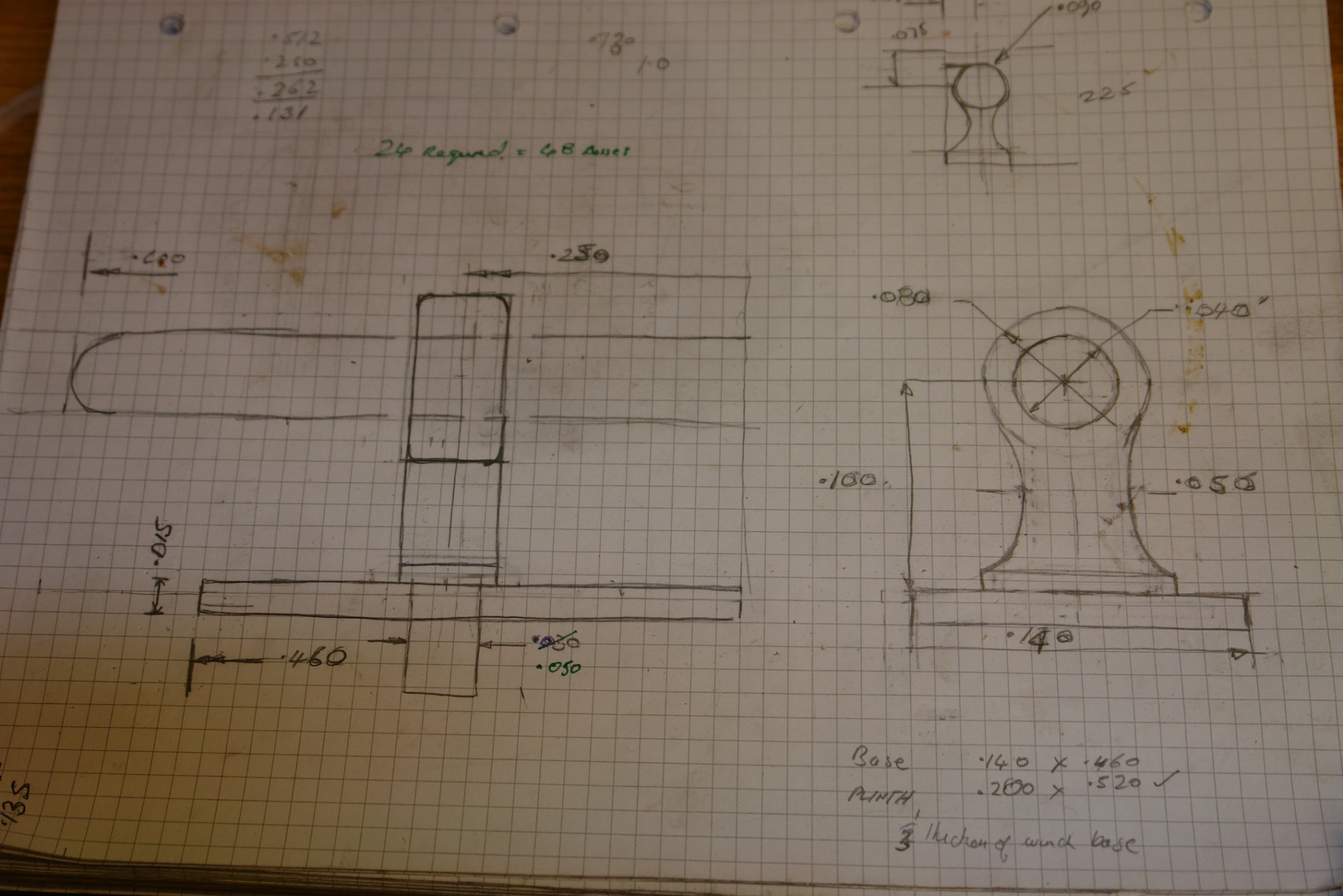
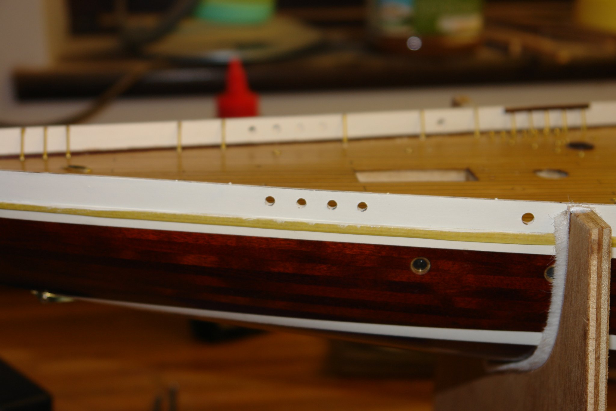
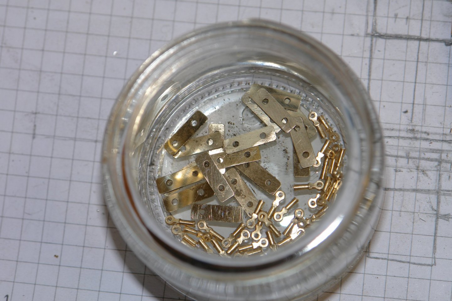
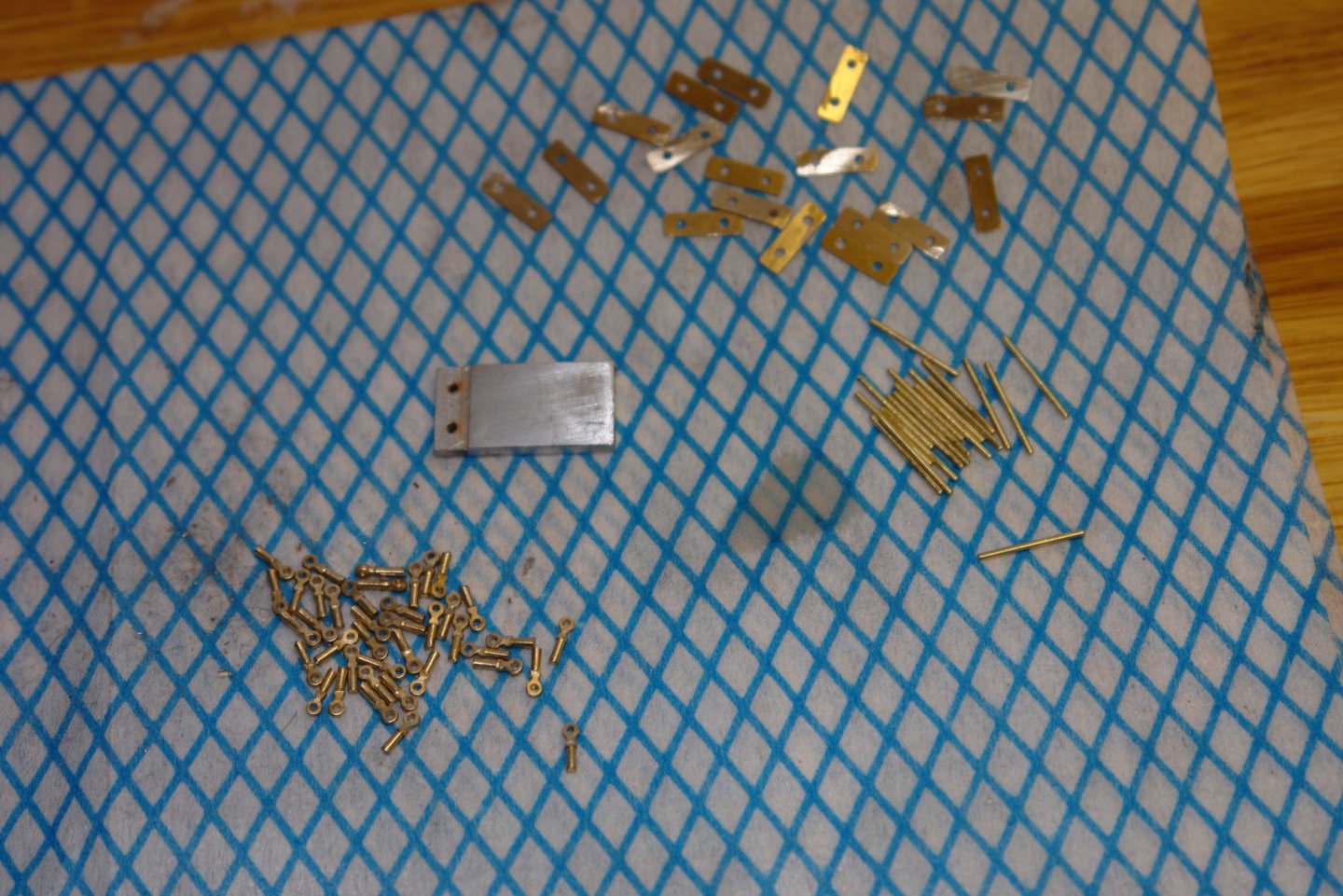
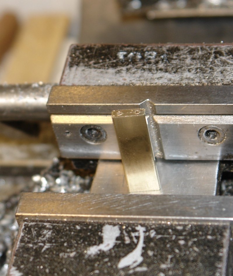
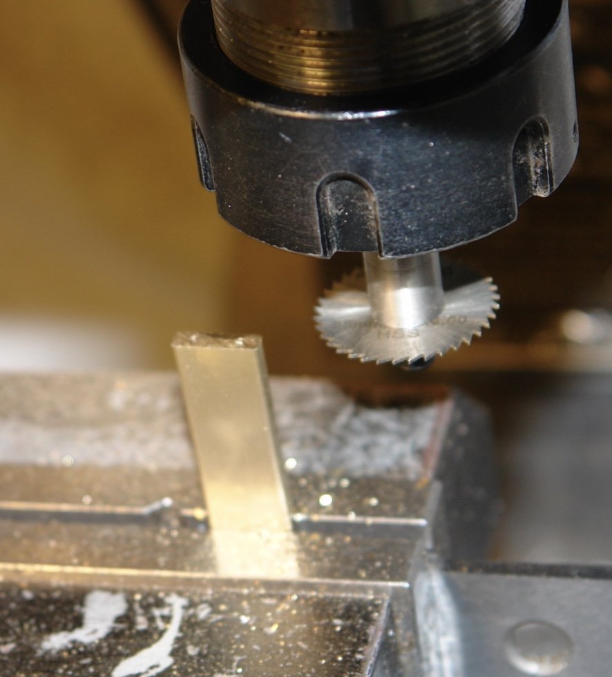
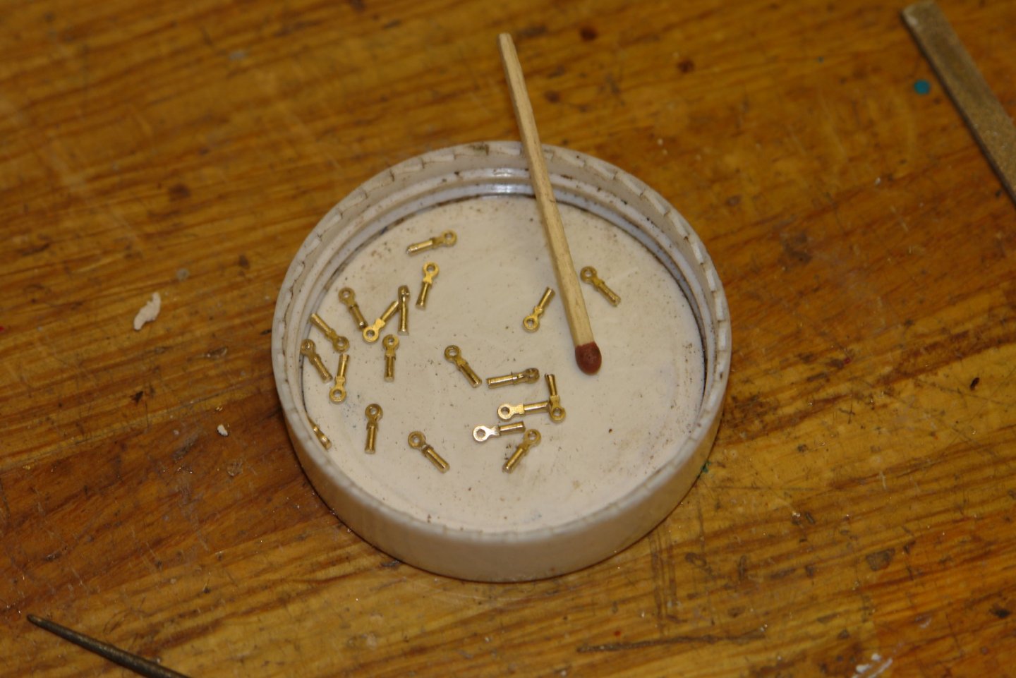
I finished off the remaining 20 pedestals and then made the cleat bases - .46"x.14" by .02" thick with holes for the pedestals .25" apart. To make them I milled a .5" x .250" rectangular brass bar down to .46"x.14", rounded the corners and then drilled .05" diameter holes lengthwise. The bases were then cut off to the required thickness using a small .028" thick slitting saw. I made the required 18 and was fortunate the the drilled holes were just deep enough. The bases were then polished by hand on one side using 2000, 5000 and 7000 grit wet and dry paper. The horizontal bar of the cleats was made from .04" brass wire cut to length using a jig. The ends of the wire were made spherical by placing the wire in the hand drill and holding it against the aforementioned emery paper. The final piece of the cleat kit of parts was a stepped jig with holes. This will be used for drilling the deck mounting plinths once they made and glued to the deck.
-
Very nice detail on the masts Dan. The blocks look very precise, were they bought or did you make them? The ratlines are remarkably cleanly done.
- 238 replies
-
- 4
-

-
- leviathan
- troop ship
- (and 2 more)
-
GL - Yes, I suppose that is inevitable, particularly when working in a difficult wood like oak. Never the less the finished hull looks perfect,
-
Hello Jon, Just catching up and loved your comment above. It just chimed with how I sometimes feel. Funny thing this creeping decline process.
-
Looks like an interesting project. I will be interested to follow along.
- 84 replies
-
- 2
-
-
- nimblet
- knockabout
- (and 1 more)
-
Druxey - that would have been my favoured option but the sternmost bulwark bracing struts are in the way and I think they will prevent the grating sliding rearward if the cap rail is already in place.


-
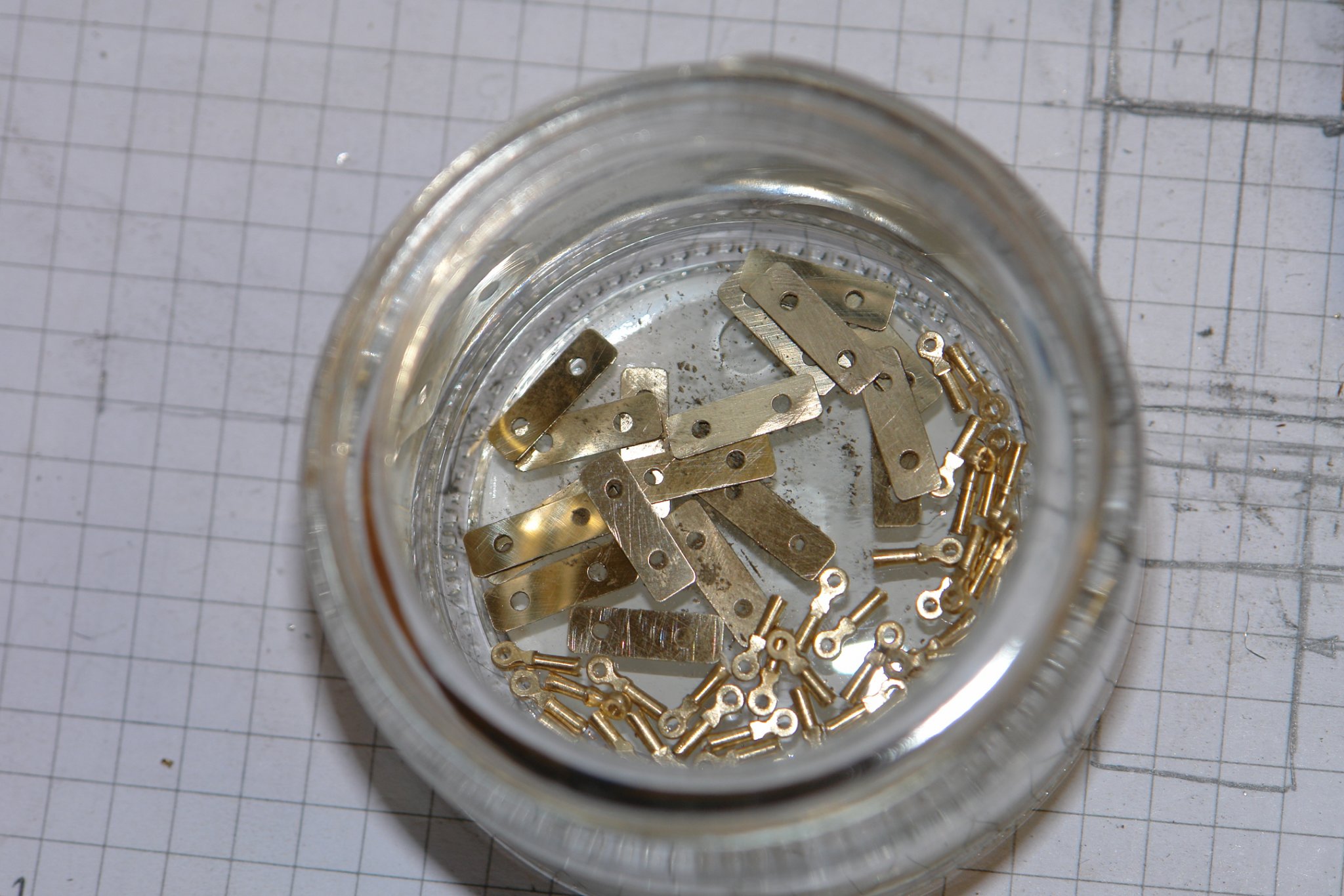
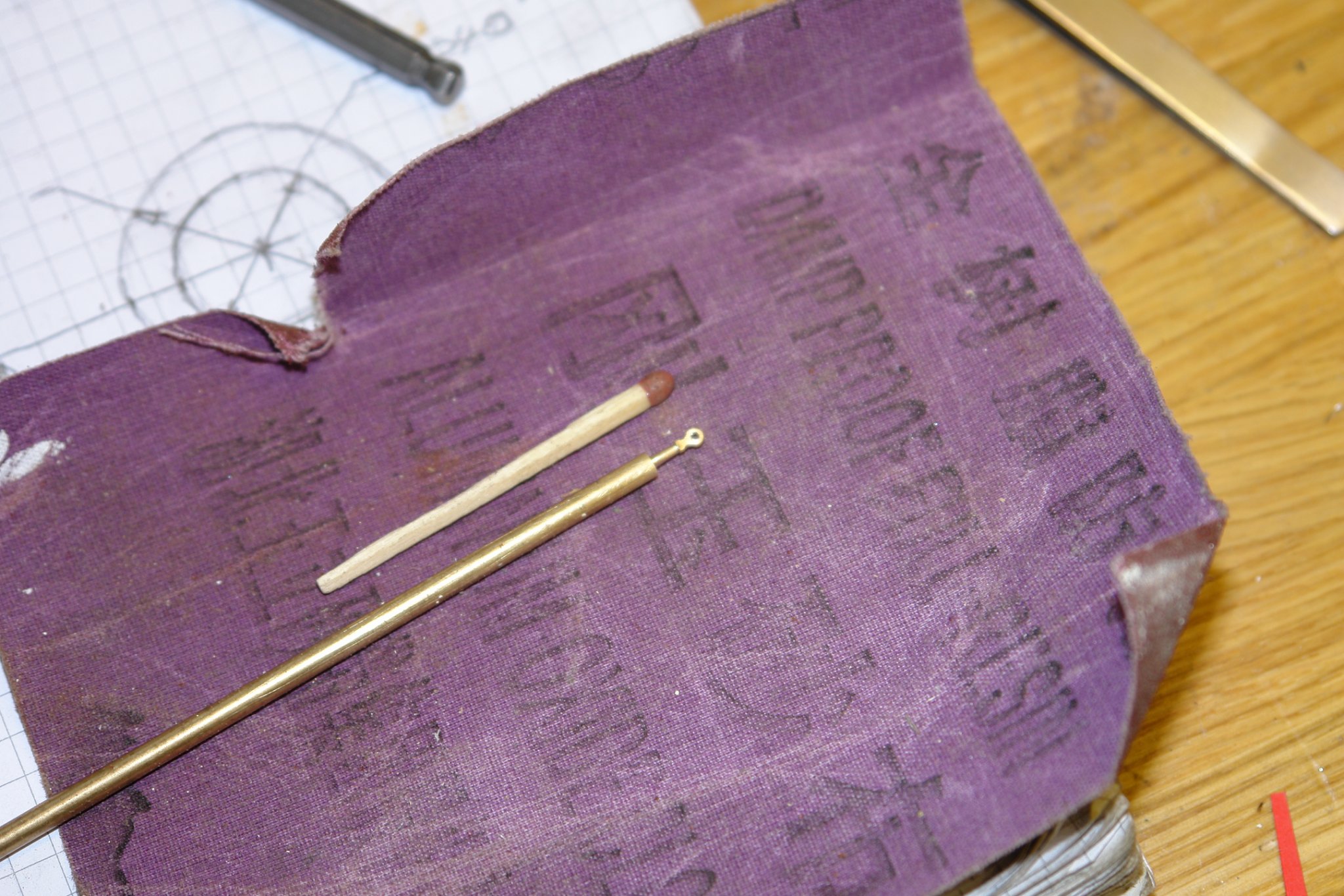
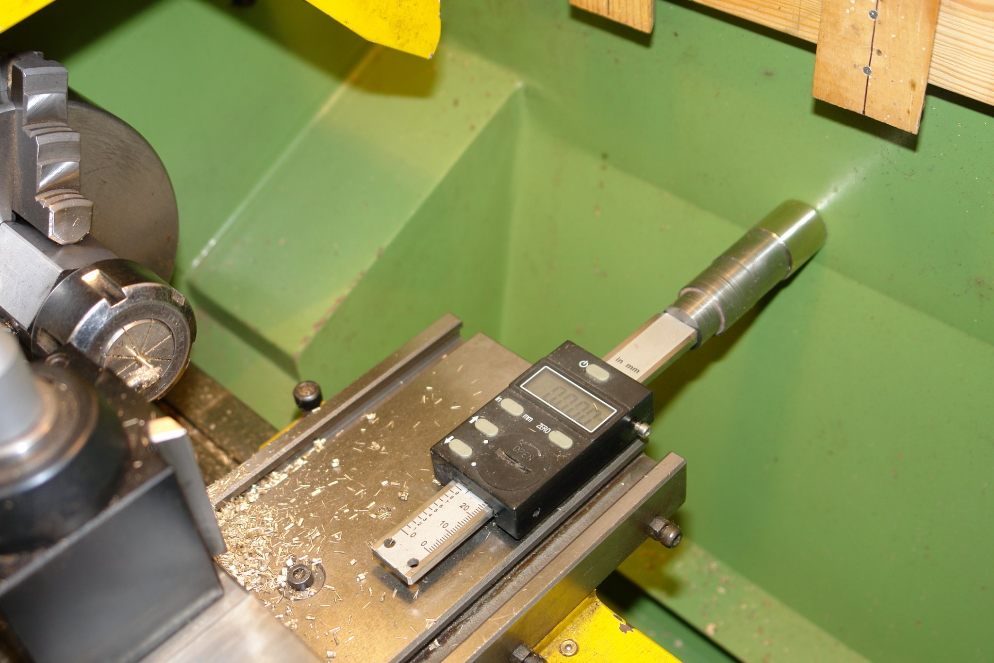
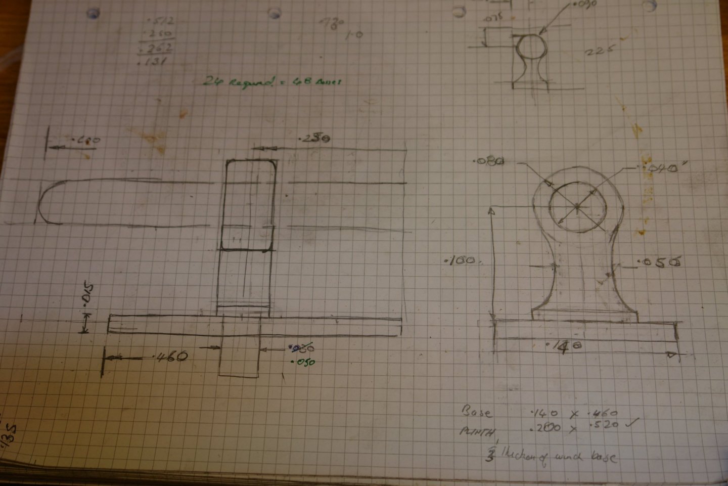
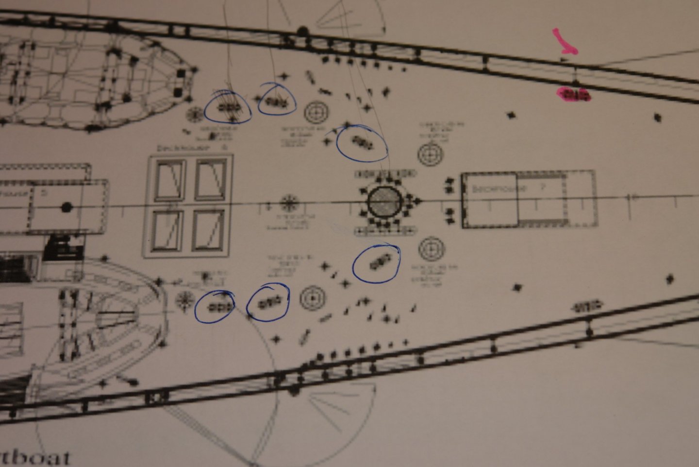
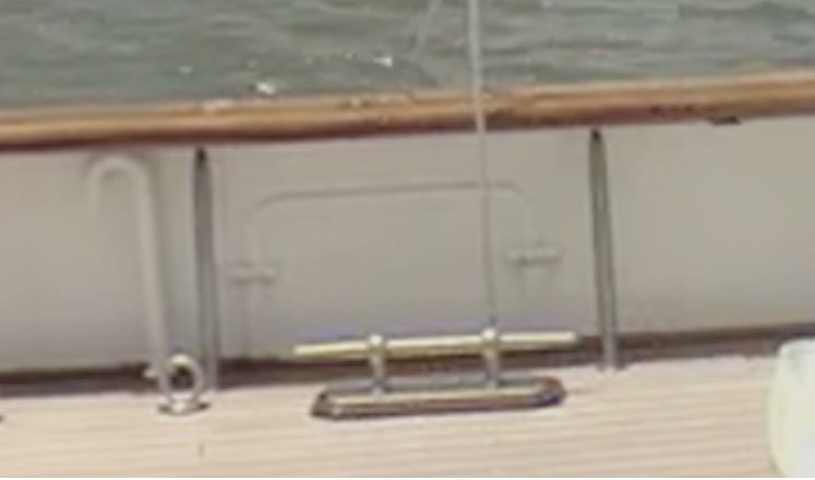
I thought I would make a start on the deck cleats. Once again the dimensions were scaled from drawings using the deck plank width of 3" as a comparator. From the photos I drew a scale sketch. The key element is the pedestal. It looks big on the drawing but in fact is a little over 1/8" high. All pedestals of course need to be identical and the initial cleat count 24 led to a requirement of 48 pedestals. Mindful of earlier problems with the plans I did a check of the deck cleats against the photographs. This confirmed all of the cleats with the exception of the 6 associated with the foremast. While these cleats were on the plan they were definitely missing form the photographs. This is a bit odd as in my experience winches and cleats tend to appear in pairs. 2 missing can be explained by the deletion of the 2 winches discussed earlier but why the other 4 have gone missing is a bit of a mystery. Anyway the original requirement for 48 pedestals was reduced to 36. As with the eyebolts I started by making a form tool. This was made to create a .090" diameter ball on a .065" diameter shaft. The plan was to turn the neck and the shaft (using the form tool) and then use a round ended lathe tool to create the concave neck profile with a minimum width of .050". As previously the stock was mounted in a hex collet block and then in the lathe chuck. The saddle was locked to the bed and the form tool plunged in the make the ball on a shaft. To make the plunge depth repeatability easier I attached a spare digital linear scale between the cross slide and the splash guard - held by rare earth magnets (obviously this only works when the saddle is locked). This meant I only had to note digital reading and didn't have to count and record hand wheel rotations. The plunge was made until the ball diameter was .090" The round nose lathe tool was mounted in a quick change tool holder and positioned so that the neck could be shaped with a plunge cut without unlocking the saddle. As with the profile tool the digital reading was noted once the plunge had thinned the neck to .050". Finally I turned a mounting spigot of .050" diameter with a parting off tool. Once the profile had been created I moved the hex block to the mill which had been set up to plane off both sides of the ball and shaft to a thickness of .040". As with the eyebolts the x axis was locked as was the vertical (Z) position of the cutter. The cut was made by winding the y axis of the mill. Finally a .040" diameter hole was drilled in the same way used for the eyebolts and the pedestal was cut off using a jewellers saw. After a few hours work I had the first of the 36 pedestals. (in the following photograph compared with a standard sized safety match). With all the setup stuff completed It took 90 minutes or to make the next 19. Now only 20 more to make (including 4 spares for black hole problems).


-
Very nice woodwork GL. I note you work in a T shirt. Is it particularly warm in Belgium at the moment - unlike this side of the channel?
-
Sad news to hear of the passing of an exquisite craftsman but at least his exceptional legacy will inspire future generations of modellers.
- 281 replies
-
- 4
-
-
- falls of clyde
- tanker
- (and 2 more)
-
This is correct and in addition I would advise against wearing rings while doing machine work - they also lead to missing digits.
-
Pat - If you look carefully you can see the seams - so I believe they lift out. They only sit a few inches above the deck and in that location (where the hull depth is very shallow) its hard to believe that anything below requires access. Indeed it is a bit odd that the gratings are required at all. How are you getting on with sorting out your lathe eccentricity problems?
-
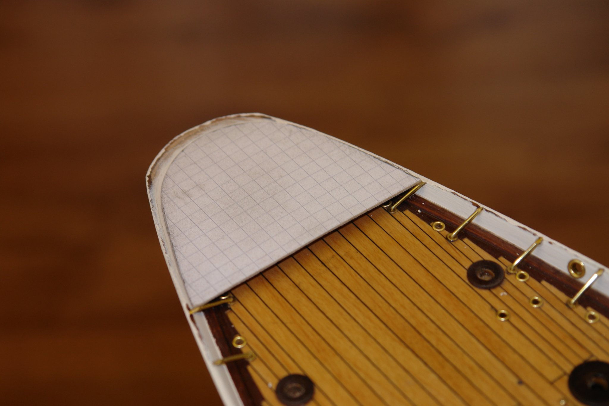
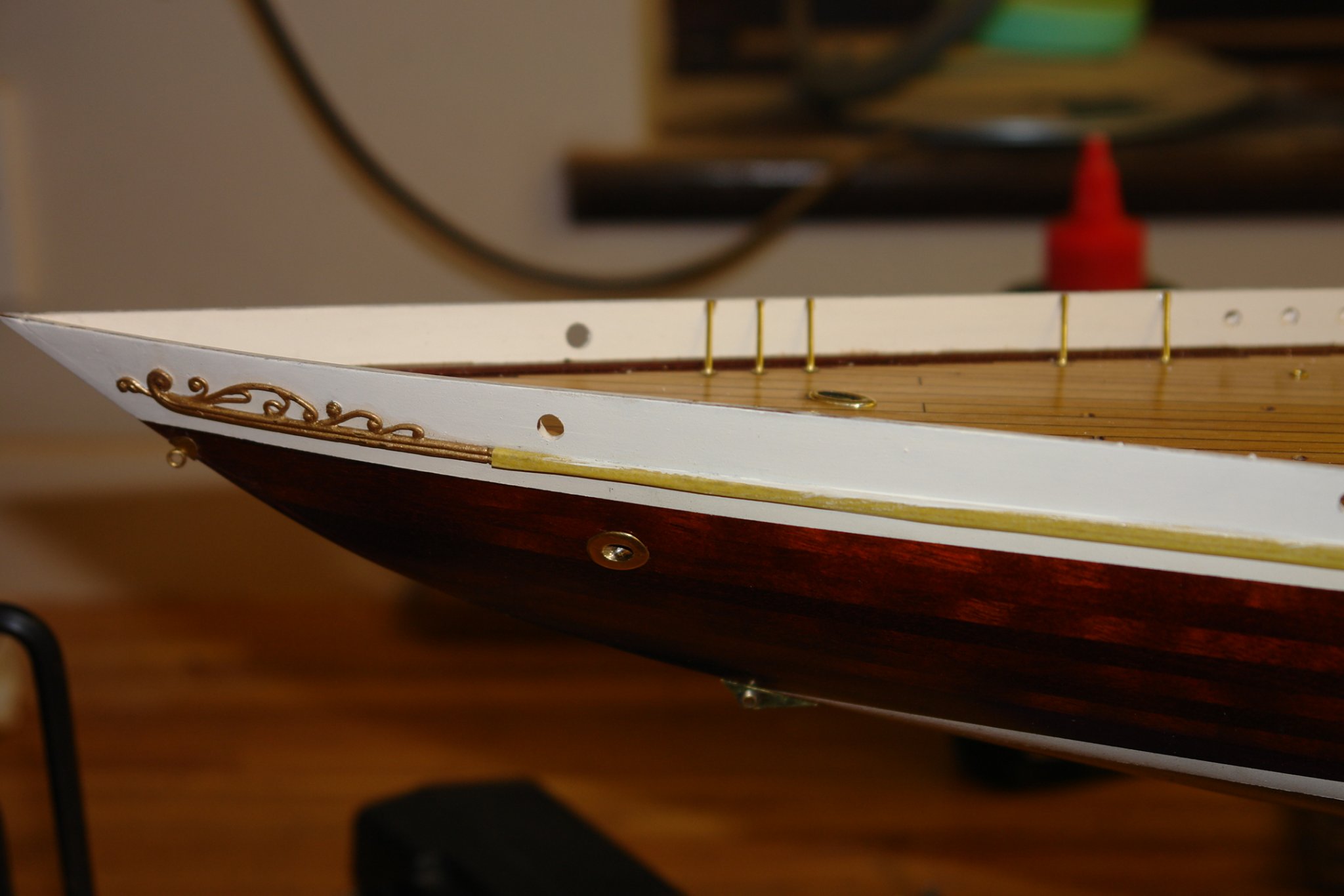
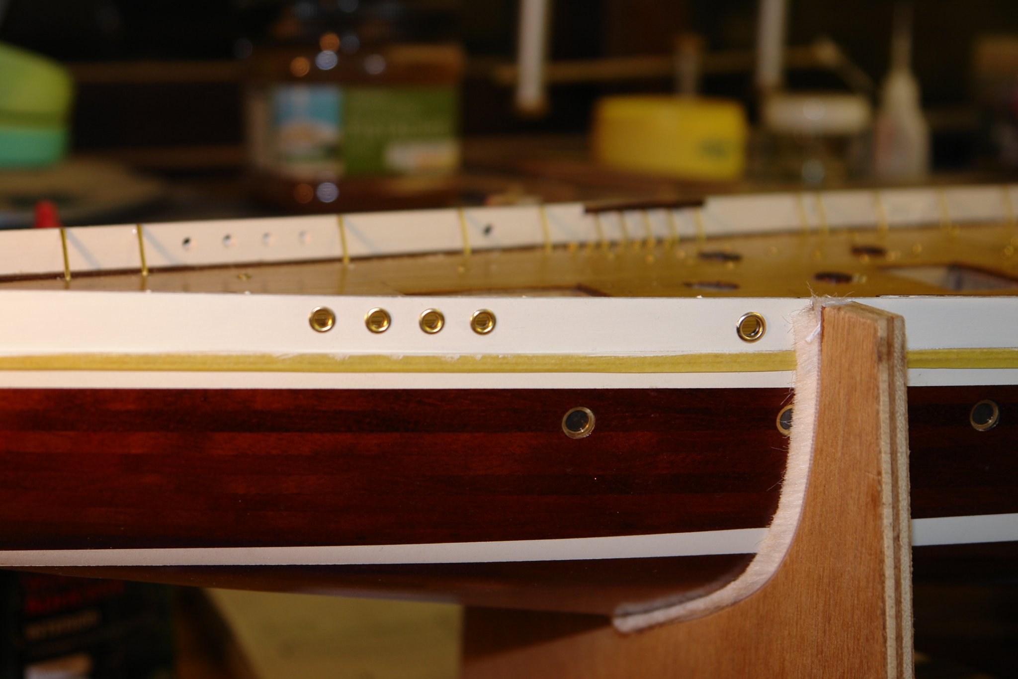
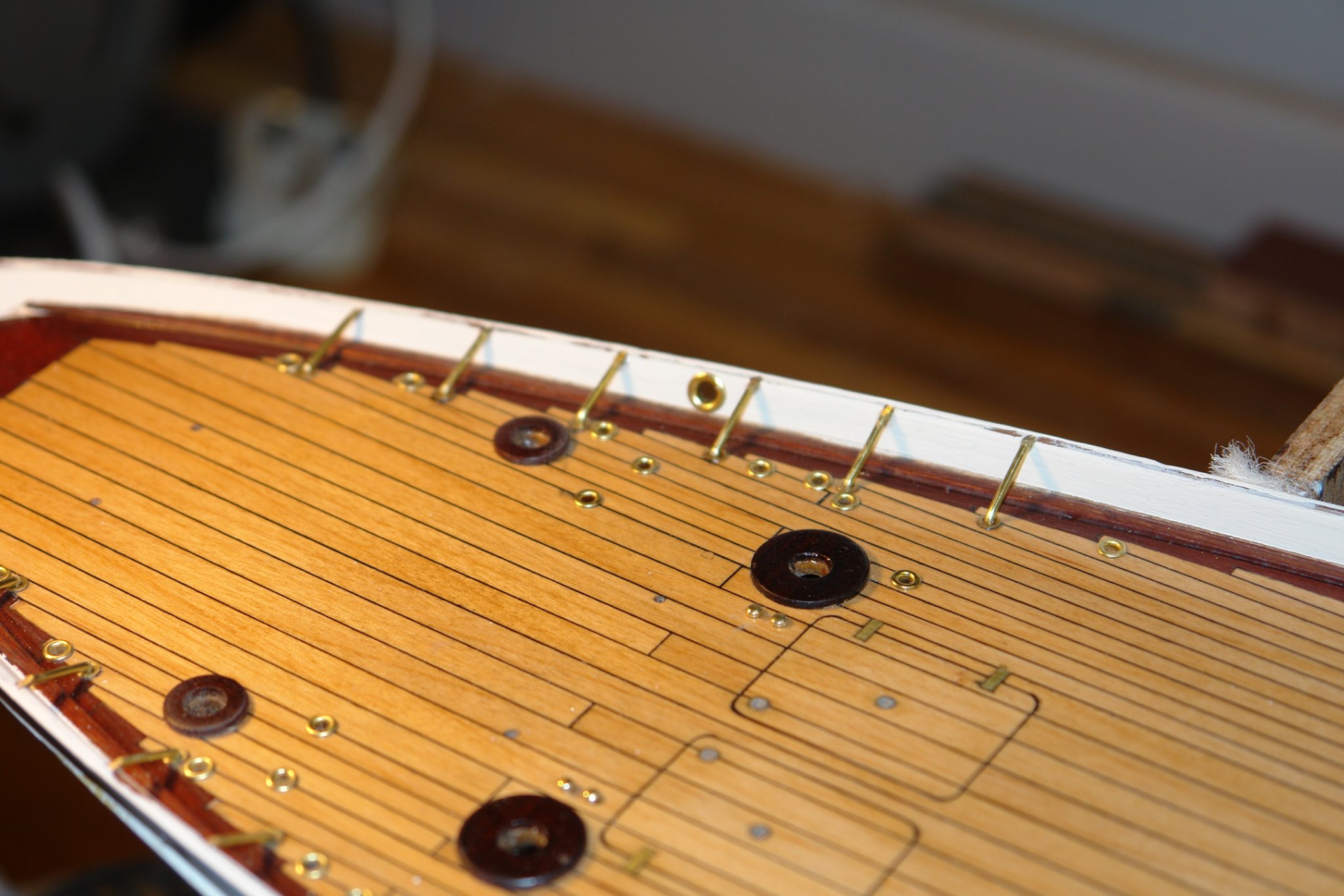
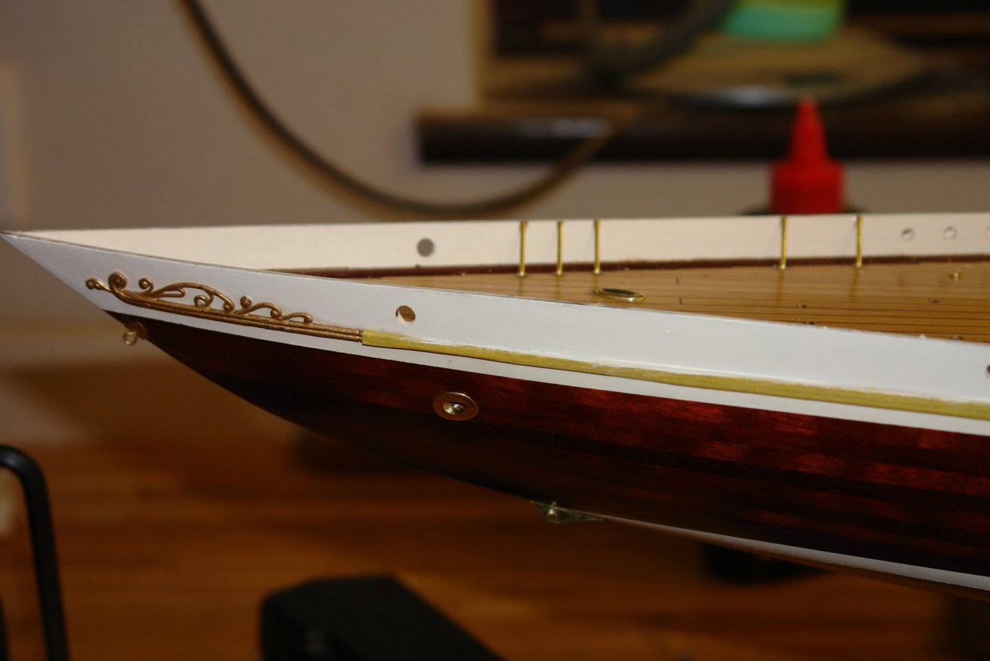
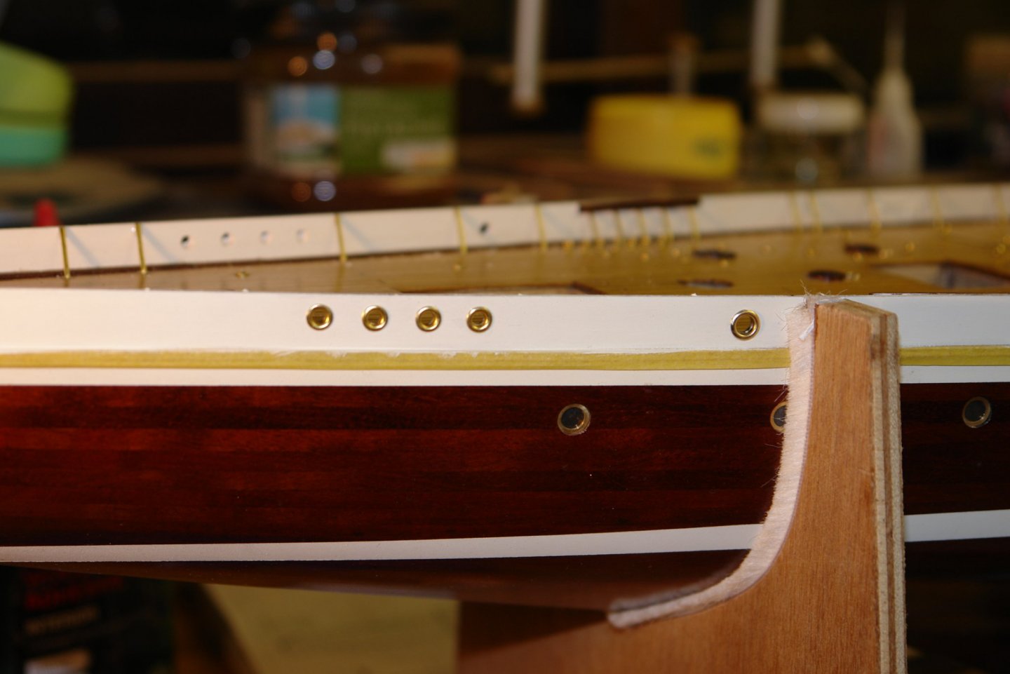
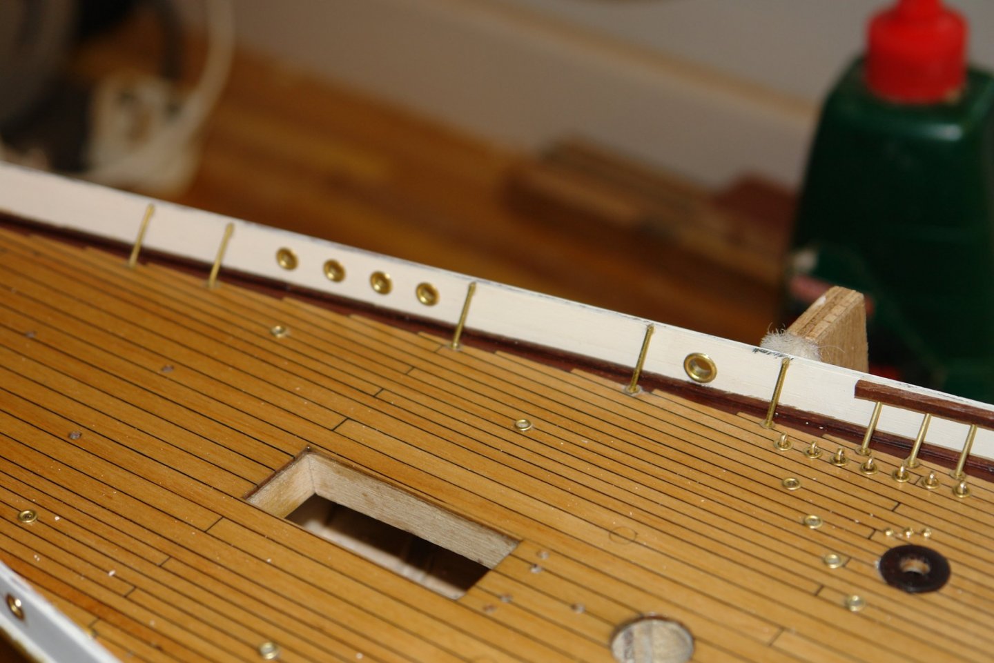
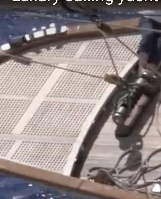
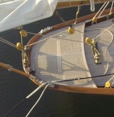
Having finished the struts I progressed the fitting of the bulwark penetration reinforcing rings. I covered the manufacture of these earlier but to recap the rings were made out of eyelets with the tube part cut down to half the bulwark thickness. They were then inserted in the pre-drilled holes from either side and glued in place with CA glue. The result was quite pleasing, the joint line being invisible until magnified by the photographs. Even then the joint was barely visible. I really want to get on with making and fitting the bulwark capping rail. Not being sure how I am going to do this is praying on my mind. One of the obstacles to fitting the rail is the creation of the raised grating at the stern. This fits below the rail and has to go on before it is fitted. The plans are not much use in this area although as you can see the photos are quite good. The grating holes are very small 3/4" square at full scale or .021" at the model scale of 1/36. I thought that .021" would be a bit of a challenge in the wood I am using so decided to compromise and make them .031" square (1.1" square at full size). I spent some time measuring up and creating a template from which to work. I took the external profile from the hull by putting a piece of paper over the stern and doing the equivalent of brass rubbing. The other dimensions and shapes were scaled from the photographs. By which time the cold had taken its toll and I retired to the lounge for a warm.


-
Amazed at your CAD skills. Now all you have to do is attach a CNC Mill and you will have finished.
-
Michael - the height of the bulwark above the deck reduces progressively from bow to stern, while the distance of the deck boss from the deck edge is constant. This means that the angle of the struts constantly changes. The strut spacing is also inconsistent with some areas quite sparse of struts while others are quite dense. You might expect the maximum density to be where the bulwark is highest (and weakest) but this isn't the case. The quite low bulwark at the stern seems to have one of the higher strut densities - which is a bit paradoxical.
-
I think it is $70 - still cheap - but not if its a waste of money.
-
UK still subject to EC law - at least for a few weeks, or months, or years, or forever - depending on the vagaries of our wonderful political leaders. Anyway as we can view the site in the UK the EC Law explanation is a bit unusual. Really enjoying the build - such an interesting subject.
- 599 replies
-
- 3
-
-
- sidewheeler
- arabia
- (and 4 more)
-
Eberhard - yes, agreed. The model of the original Germania that you kindly made me aware of some time ago does not have them. Maybe they used thicker / stronger steel in those days.
-
Keith - worryingly you seem to be reading my mind. a number of valves are positioned at the deck edge and I was thinking they needed to be made and fitted soon.