


Cathead
-
Posts
3,558 -
Joined
-
Last visited
Content Type
Profiles
Forums
Gallery
Events
Everything posted by Cathead
-
 Looks great, glad you're still plugging away!
 -
Everything looks wonderful. I do agree that the marine life green should be darker and duller. Makes sense to be a bit brighter than "real" to help viewers notice it, but not quite as neon as your first try.
-
As much as I like using masking tape to simulate tarpaper roofs, I think I agree that it'd be out of scale for this project. Wefalck might be right about trying a very fine-grained sandpaper. Another possibility would be tissue of some kind, which is especially thin but will help hide any wood grain. The shed looks wonderful!
-
Yay, I'm glad you haven't stopped on this. Great progress.
-
Always nice to see a dormant build come back to life!
-
Oh, man, I actually felt nauseous for a minute when I started reading your post. So glad you were able to work it out. Looks really cool!
- 110 replies
-
- 2
-

-
- Paddlewheeler
- Ballarat
- (and 3 more)
-
Vallejo makes a "Boxcar Red": https://micromark.com/products/vallejo-acrylic-airbrush-paint-boxcar-red-1oz?keyword=vallejo boxca
-
To be pedantic, she's a lake boat! Nice-looking kit though.
-
Nice to see you posting again! Great progress. I've heard of (and worn) coke-bottle glasses, but now I've seen coke-can heat shields!
- 158 replies
-
- 1
-

-
- chaperon
- Model Shipways
- (and 1 more)
-
Yeah, I'll reiterate that suggestion. (a) it's an Ohio River boat, perfect for your location. (b) it's just about the only accurate riverboat model out there (c) there are lots of good instructions and build logs available. I think you'll find it a really rewarding next-step project. Glad you had fun with this one!
-
Loving this discussion, and to chime in on the donkey/onions question, I thought it was a Shrek reference! (Onions have layers, donkeys have layers...)
-
USS Cairo by Zetec - FINISHED - 1/50 scale
Cathead replied to Zetec's topic in - Build logs for subjects built 1851 - 1900
Nice job, congratulations on completion! -
That looks sooooo good.
-
To what extent does the weight of the machinery counter-balance the tower? It's placed at the other end of the barge in a natural setting to do so, in both Keith's plans and all the historic photos shown earlier. And as already said, some additional ballast would go a long way. As for overall tipsiness, yeah, I wouldn't want to be out on open water on a windy day on one of these, but presumably they were almost always tied up to something else stable (existing piles, tugs, etc.) while working and only moved under stable conditions. For example, I've watched modern barges doing bridge work hosting huge cranes that seem like the whole thing should just topple into the water, but between the barge being tied up solidly to something and the crane well-balanced, it works.
-
Yep, Jay's showing exactly what I had in mind.
-
Always nice to see someone back at work on a dormant project. Hope you enjoy finishing up!
-
Yeah, Gary nailed it, explained it better than I did.
-
If the ground-up scenic foam is too coarse, you could also simply use the scenic grass powder also sold by the likes of Woodland Scenics. Real problem is that you only need a tiny amount of either product, so buying a whole bag is a waste. Your sawdust idea is a great way to get around that.
-
Keith, the one suggestion I might make is to make the color palate of the weathering more complex. Right now the deck especially is all tones of brown, at least to my eye, and has a hint of old stained furniture as opposed to a grimy deck. Some shades of grey or black might help balance that. Maybe also hints of rust around the metal fittings. You could even think about or map out where crew were likely to have walked and make those routes darker. This is the kind of thing where pastels excel.
-
I dunno, I've heard of lots of ships having more than one port, it's just the multiple starboards that get confusing... Great work, your weathering looks just right so far.
-
LOL, I thought you were getting all maudlin on me, as in "we're all approaching our final johnboat someday". Even if I wasn't shifting to railroading for a bit, I'd be taking a break from riverboats. I've built enough of them that finishing Peerless felt like a bit of a grind. My personality needs a really new challenge every now and then.
-
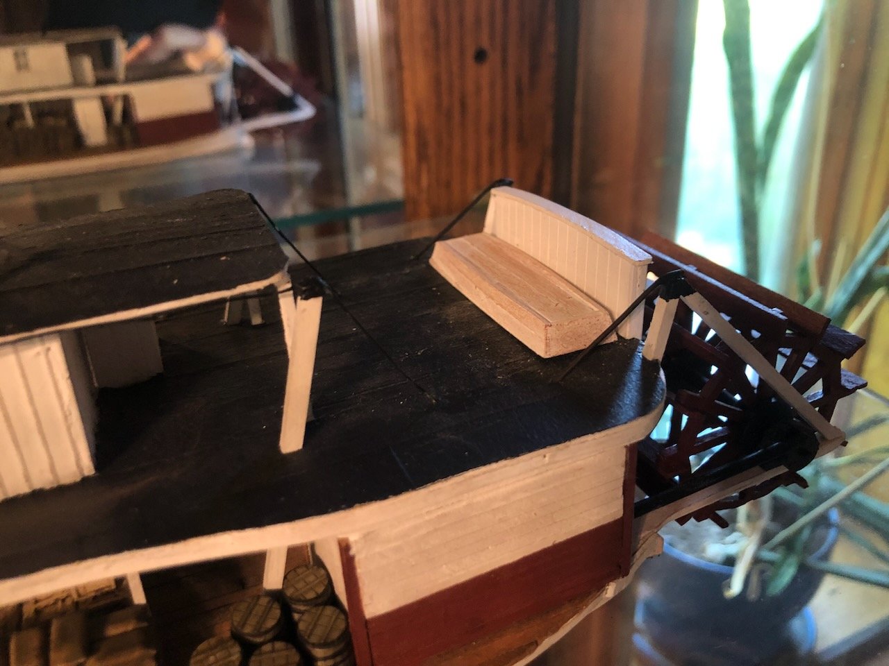
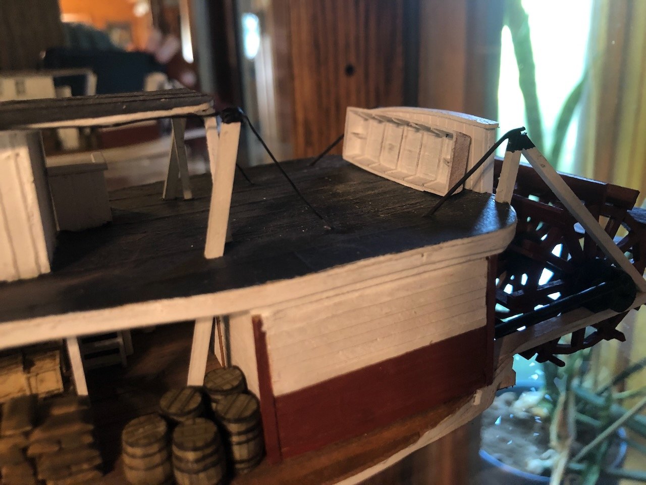
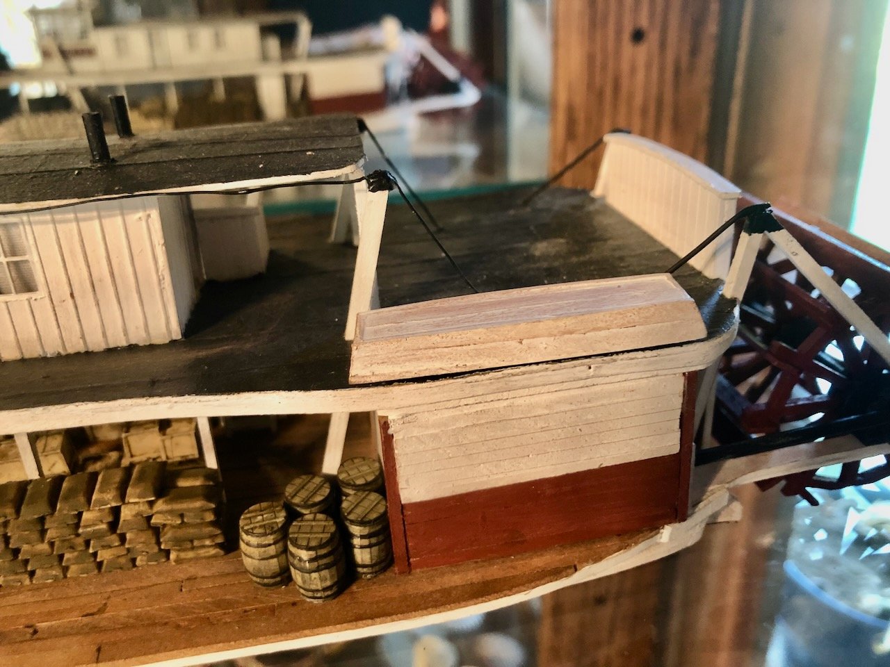
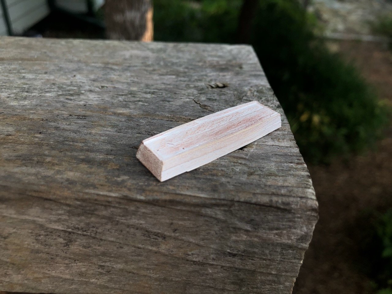
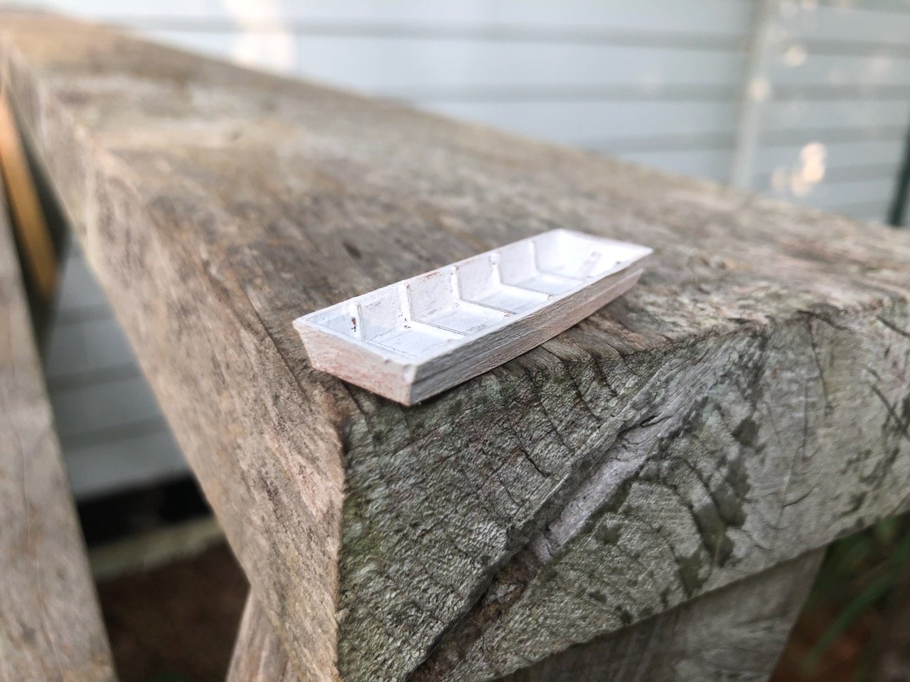
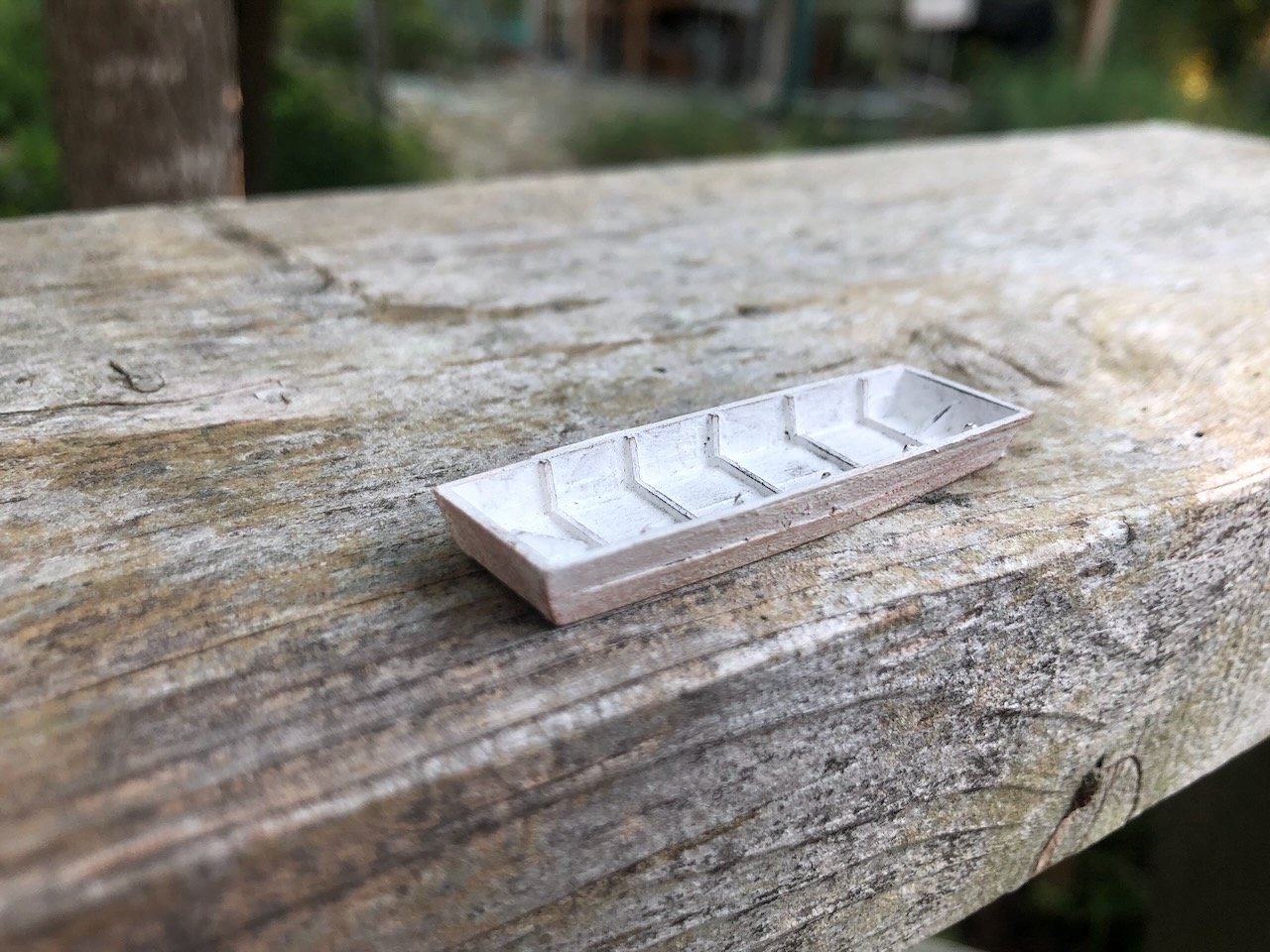
Keith, are you channeling Tennyson's Across the Bar? So I finally recognized something that was bugging me about my johnboat; it's too tall. It looks like a bathtub. So I cut it down by one whole strake and it looks a lot better. I also added interior ribs and muddied-up the exterior; there's no way any boat that's been in the Missouri River stays white. Here's the new outcome. And here are the three display options, each of which has a historical record: I'm leaning toward one of the two at the stern; upside down seems a little more practical for keeping water out but on its side shows more detail.
- 393 replies
-
- 17
-
-
Mark, this year was the 19th iteration of the race, so it depends on when you left as to whether you ever had a chance to see it! Thanks for all the comments and such. I'll have a final johnboat to share with you all soon.
-
Congratulations on finishing! It was neat to see you having so much fun with this kit.
- 87 replies
-
- 3
-
-

-
- King of the Mississippi
- Artesania Latina
- (and 2 more)