Cathead
-
Posts
3,522 -
Joined
-
Last visited
Content Type
Profiles
Forums
Gallery
Events
Everything posted by Cathead
-
 Yes, there would be a safety valve atop the boiler and the venting pathway runs through a pipe that connects to the chimney. Steam for the engines draws off the top, there's usually a cylindrical drum up there, from which piping runs back to the engines at the rear of the vessel. Here's a view of the full machinery setup on my Arabia. You can see the steam drum, the piping to the engines, safety valves on both sides, and the vent pipe leading to the right side of the breeching. : I'll be adding these features, though some of them can't happen until the boiler is installed (rather than ahead of time). What I meant when I said no more detailing was that I wasn't planning on subtle things like rivets (unlike Arabia above), sorry that wasn't clear. I'll also be adding the "doctor" pump you see right behind the boiler, which was used to draw river water up for the boiler. There's a mud drum suspended below the boilers that was used to settle out the river's high sediment load before entering the boiler. That drum is already installed on the Peerless boiler, you can see it if you look closely. Arabia was at 1:64, whereas this is at 1:87, so I'm being a bit more simplistic with the smaller scale for sanity's sake. Thanks for the good questions!
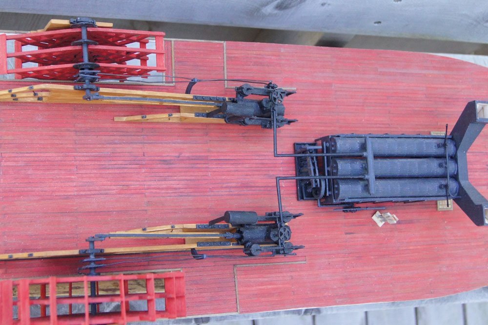
- 393 replies
-
- 14
-

-
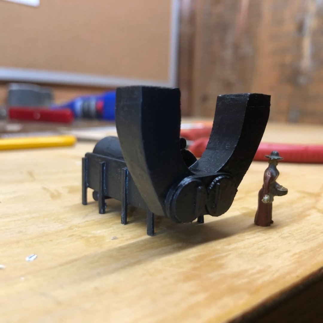
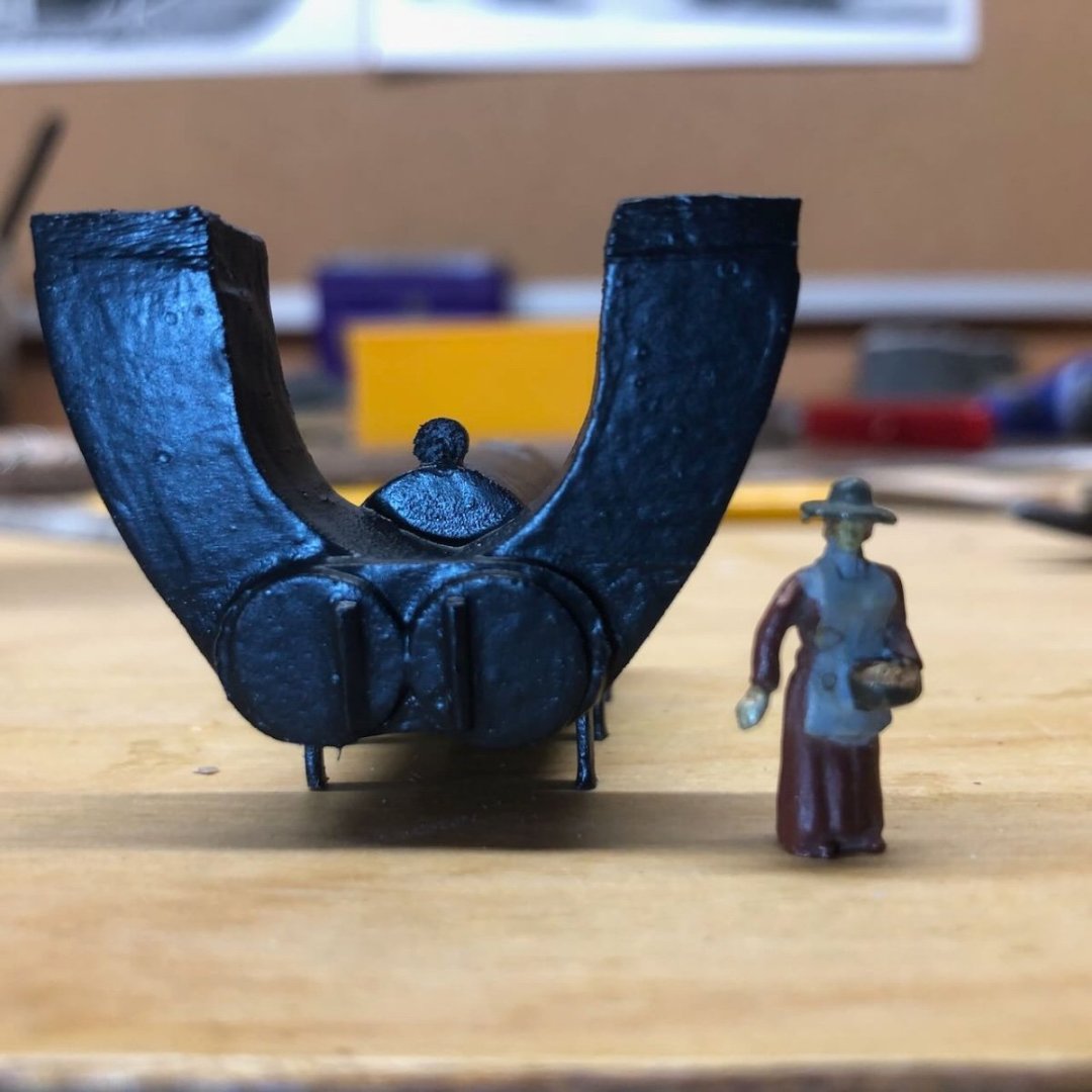
And one final update from a quiet New Year's Eve. I pulled apart the original boiler and used a dremel along with hand tools to carve and sand the breeching down to a slimmer form that I find more appealing. I also shortened the legs supporting the boiler. The final difference is subtle but I'm much happier with it. Here it is after priming and painting; also note I added a pressure gage atop the front of the boiler. Some of the dimensions don't quite match up to the original photo, but I'm ok with that. I don't feel like detailing it any further, as it is it'll blend nicely into the shadowed background of the overall model. Happy New Year to all of you!
- 393 replies
-
- 11
-
-
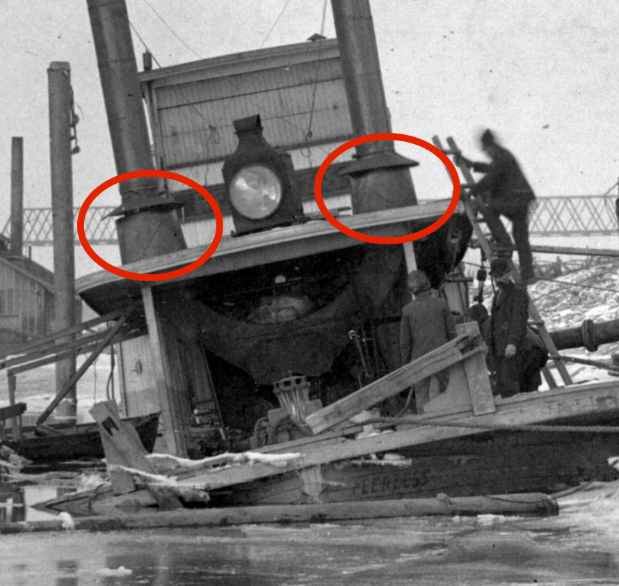
That's definitely happening above the boiler deck. I thought Kurt was referring to the underside of the boiler deck, where the breechings go up through. Here's the one decent front view I have. You can see the single boiler, the two round firebox doors, and the breechings going up through the boiler deck to the stack. I've circled the heat shields above the boiler deck, which will fully obscure the connection between the chimneys and the breeching when viewed from above. What I thought Kurt meant was that, looking up from underneath, the breeching still shouldn't be in immediate contact with the wooden framing on the underside of the boiler deck. I agree, but am emphasizing structural support over accuracy since this detail won't be very visible on the finished model.
- 393 replies
-
- 10
-
-
Thanks, Kurt, you're right but I decided that I cared more about increased structural strength than that particular detail. A close and knowledgeable eye will see that they're touching, but the vast majority of viewers won't realize it, and I'm more comfortable having the forward part of the boiler deck supported by something a bit more solid than a few spindly posts. This is especially true for Peerless, which unlike other steamboats I've built, doesn't have any solid superstructure anywhere under the boiler deck forward of the enginehouse. No staircase, no intermediate walls, nothing. So I just feel better using the breeching as a support and sacrificing a bit of accuracy.
-
Yes, riverboat boilers are single-ended; the firebox is fed at the same end as the exhaust, unlike a locomotive.
-
The steam locomotive is a good comparison and a fun question. I'm not sure how much a small steamboat like Peerless weighed, but was it significantly more than a single-locomotive freight train of the 1900s? And she was probably carrying most of her heavier loads downriver (like bulk flour/grain). Her boiler looks smaller than a locomotive's, but again she's a lightweight timber craft operating on water.
-
Companies like this don't care much about accurate details or rigging. That's a ludicrous way to lash down a cannon. One option would be to rig them at the gunports like any normal naval cannon. Guns could also be tightly lashed sideways, as in a severe storm or just for a ship that really didn't intend to need them very often (like Beagle). I went looking for a diagram for you and had some trouble, but this post on MSW shows one possible way to do it (click the link to see the drawing; the third illustration is what you're looking for).
-
I thought to check Alan Bates' definitive reference (foolishly not doing so before), where he refers to that structure as the breeching. Guess I'd forgotten that, not like I haven't perused that book ten times. After sleeping on it, I think I'm going to pursue the usual modeler's curse and partially tear down this first draft to improve it a bit.
-
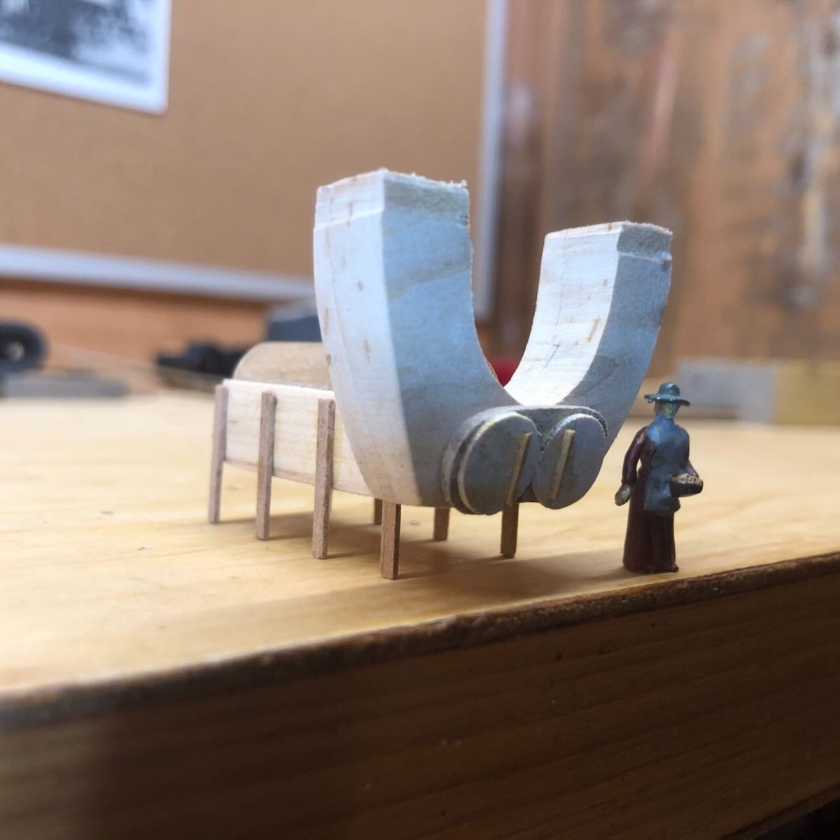
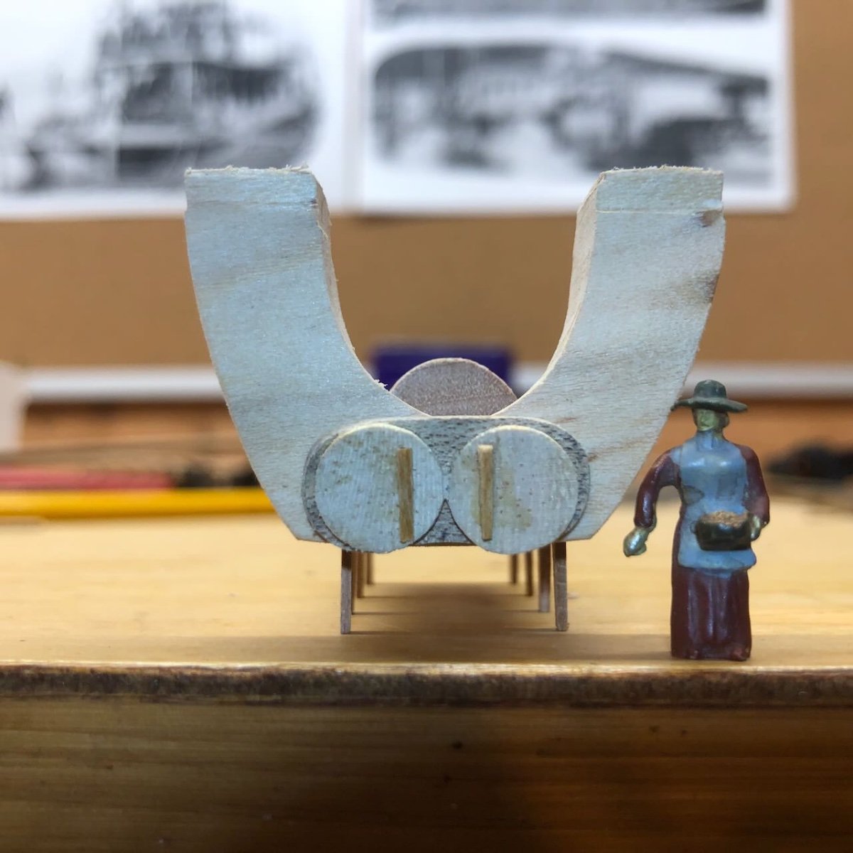
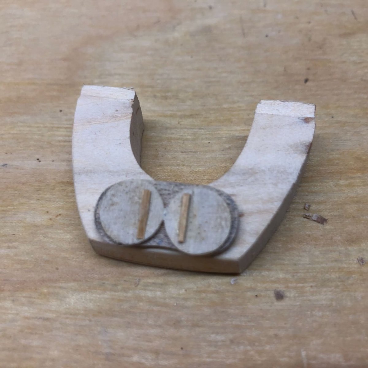
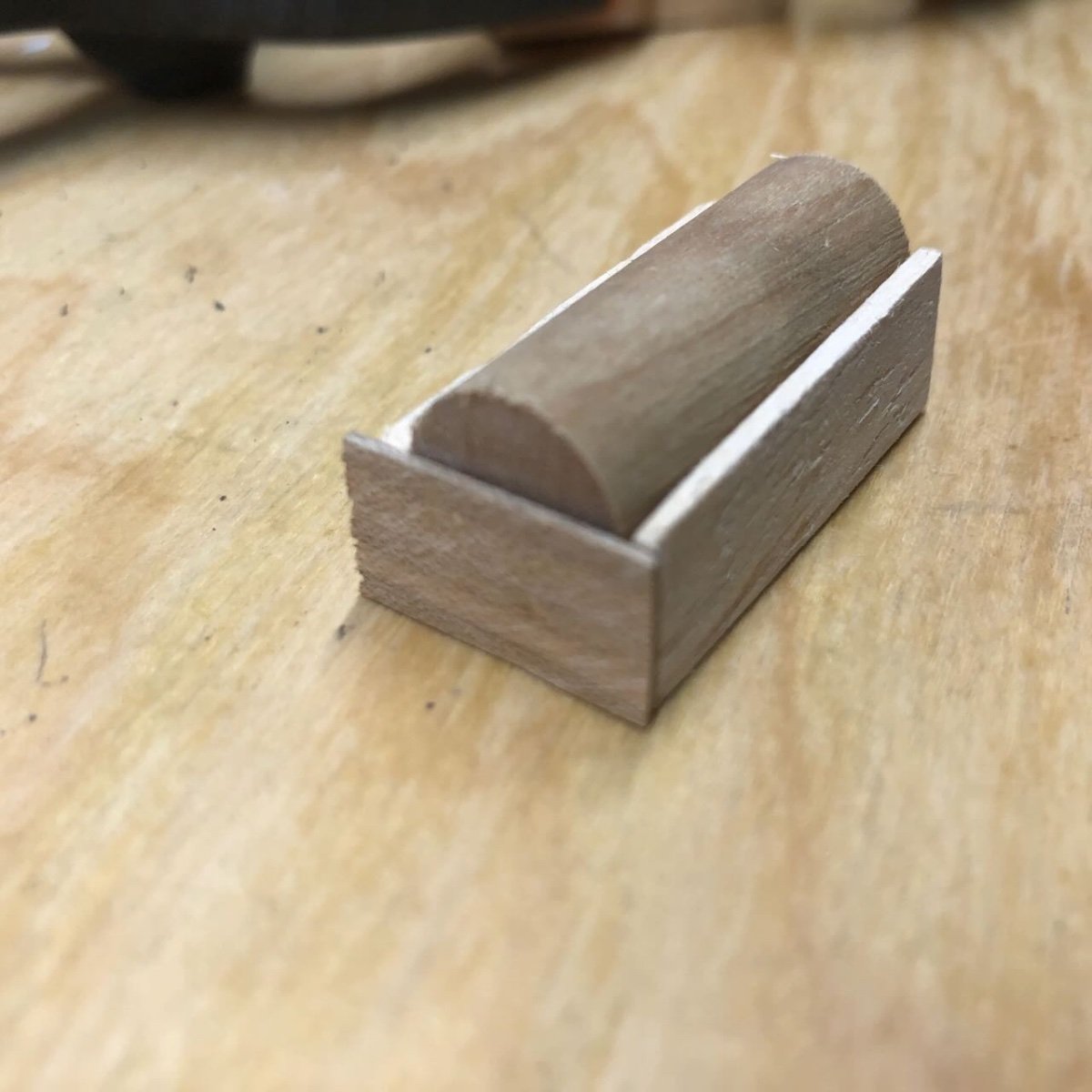
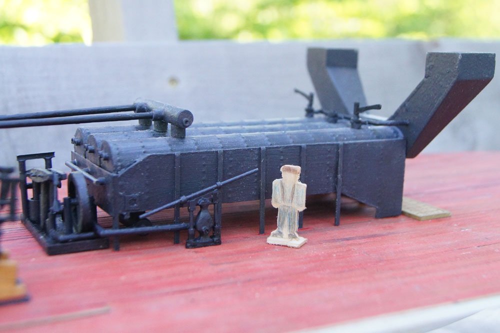
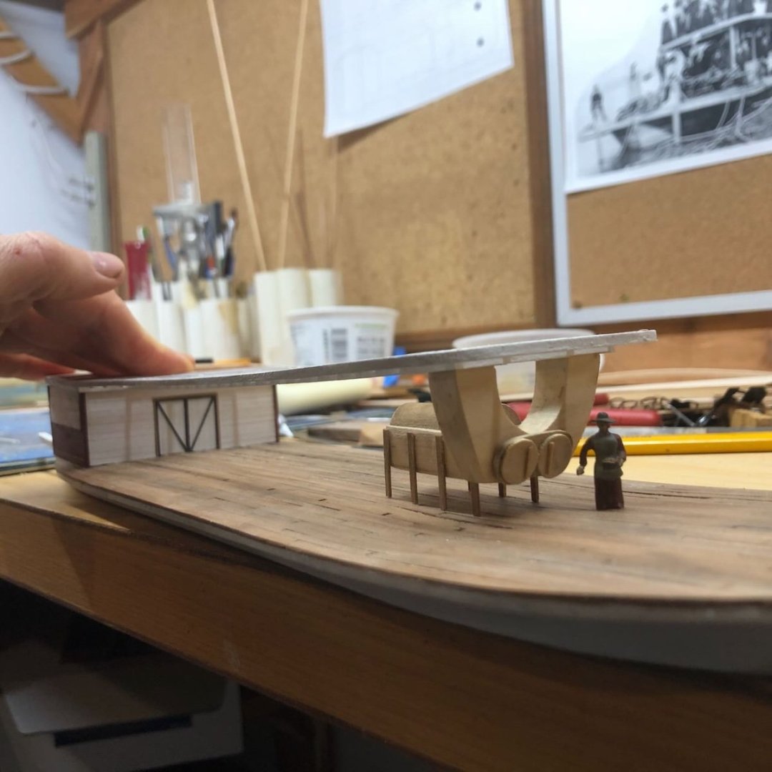
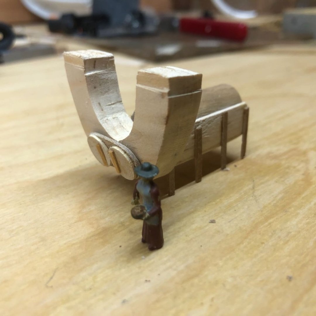
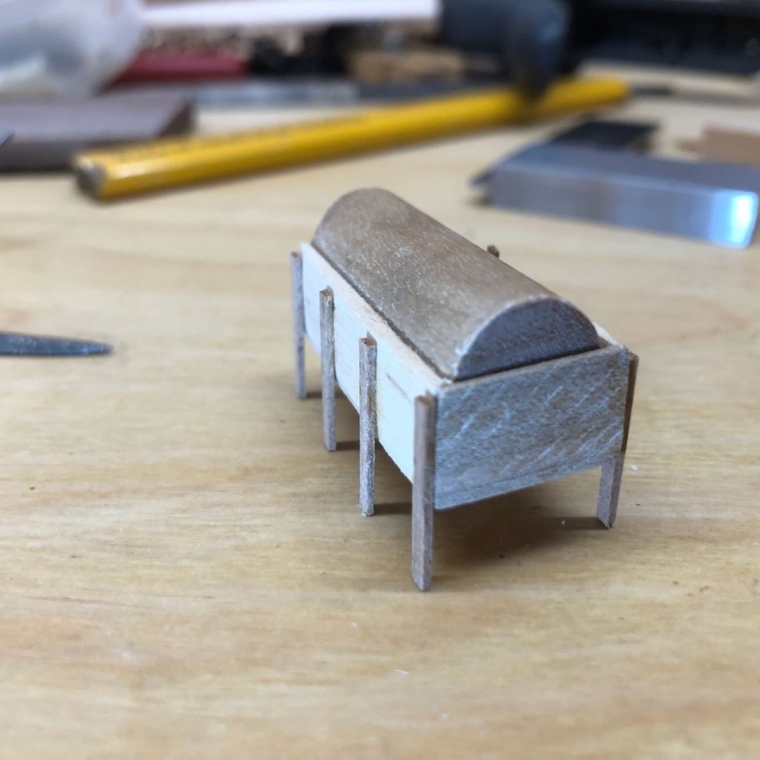
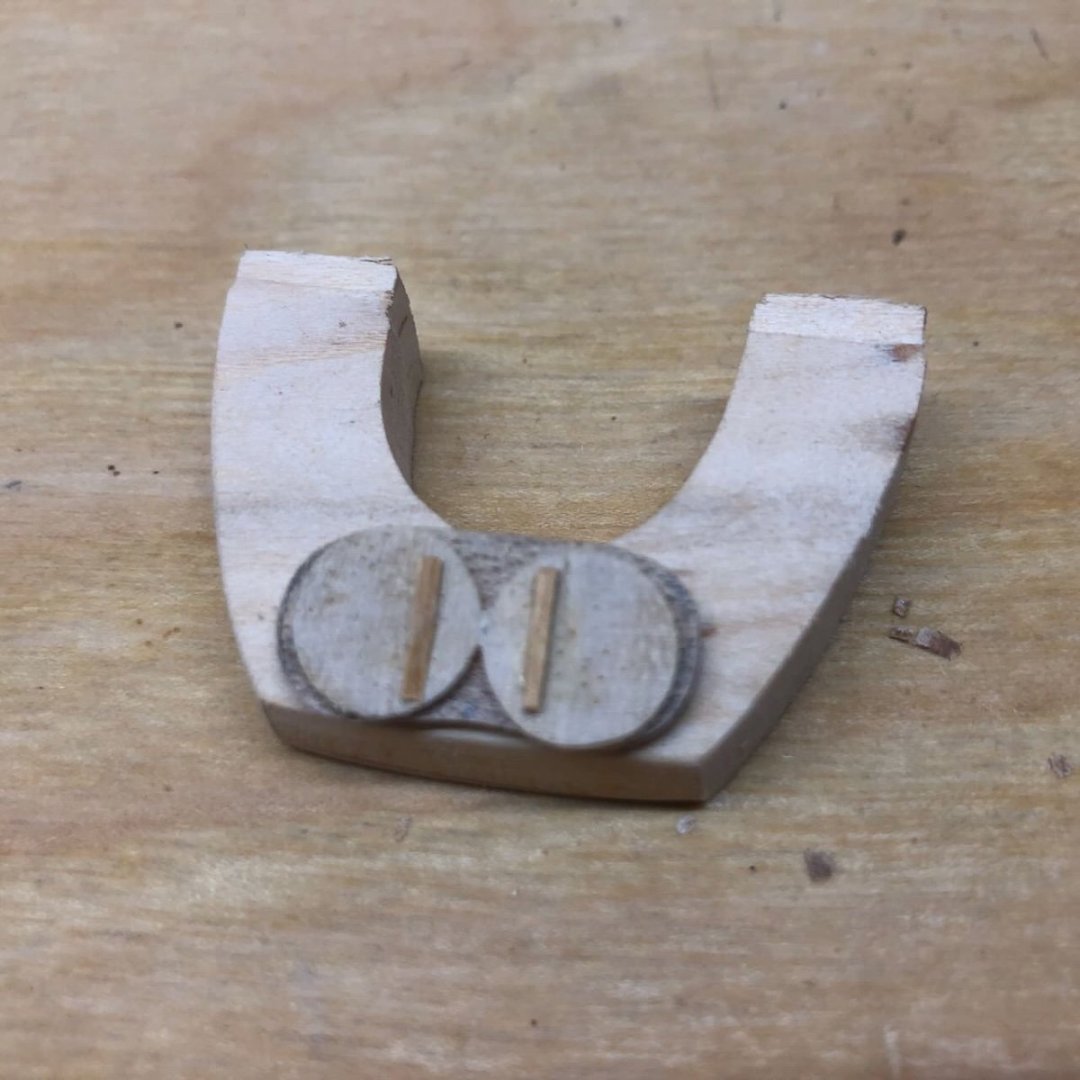
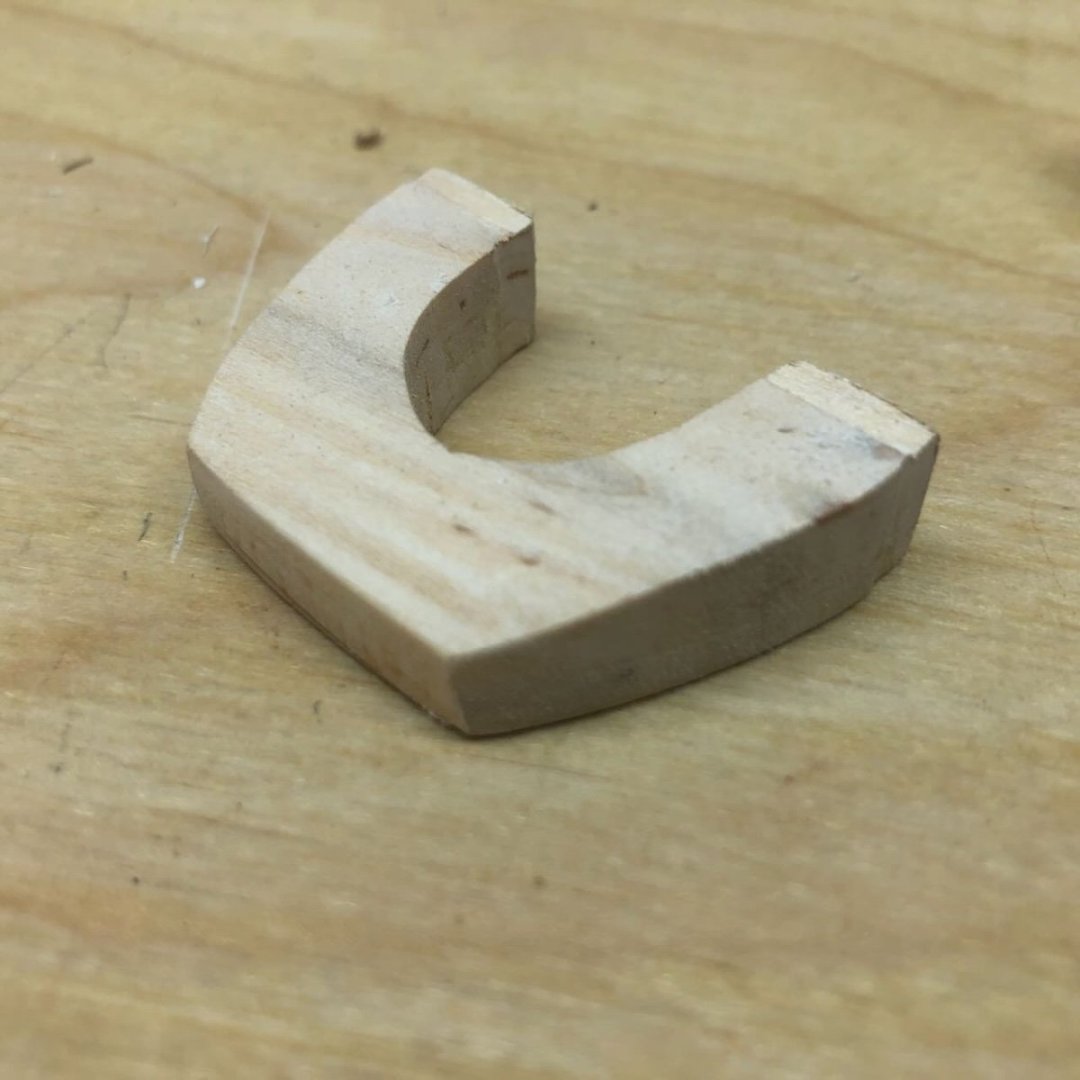
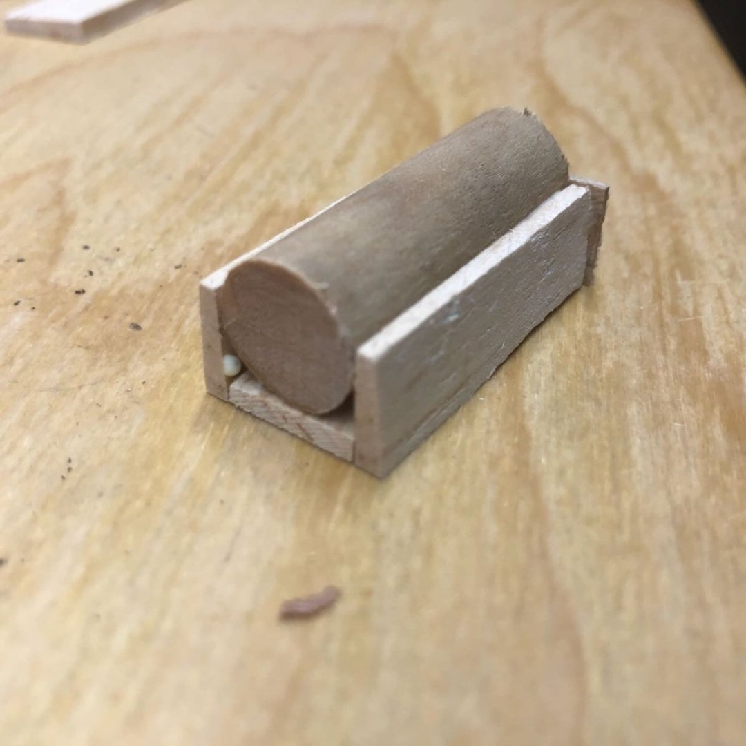
Started working on the boiler today. I don't have any good photos from the side and only one from the front that can be zoomed in but is grainy. Way's Packet Directory says Peerless had only one boiler, which makes sense for such a small vessel. So I just started laying out a basic generic boiler design based on the larger ones I've built for bigger vessels, with a single boiler tube surrounded by a rectangular casing. Here I'm using a wooden dowel and some thin pieces of farm-milled basswood. I then drew out a pattern for the complicated piece that connects the boiler to the chimneys (not actually sure what this is called; anyone know? @Roger Pellett? It took two pieces of basswood glued together to get the right thickness, though I then had to cut it down again. Then I used a bandsaw and hand tools to rough out the shape I wanted: And used scrap wood to build two basic round doors, which can be dimly seen in one original photo: When I was reasonably happy and had sanded everything pretty smooth, I added legs. Then glued the two main parts together. Here's the full assembly with a person for scale: And here it is on the model, with the deck loosely held in place: I think it's a bit too tall; I might try to carefully cut down the legs just a bit. The tops of the chimney-attachment-whatevers are slightly notched so that they fit into the square holes I framed within the overlying boiler deck (you can see this in the preceding photos). This not only helps them hold the deck in place, but also lets the deck rise at a slight angle to the boilers, as it should. So that's the loose idea. If I decide to keep this version, I'll prime it and then give it a nice coat of black and then some pastel rust. I think it's good enough but want to sleep on it. It looks kind of rough in raw wood, but when painted black and hidden in the shadows below the deck, I'm not sure there's much point in trying to make it too perfect. It also needs a few more details, like a mud drum and so on. Thoughts? Specific concerns or improvements?


- 393 replies
-
- 15
-
-
I enjoyed visiting this vessel a few years ago, will be fun to see how you make the kit your own. Great work on the boat so far!
-
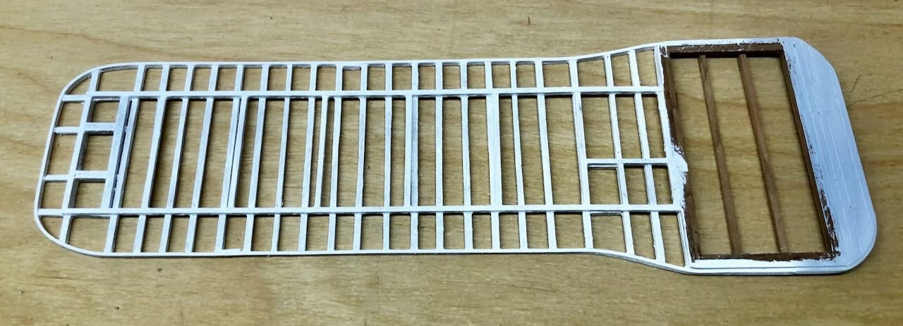
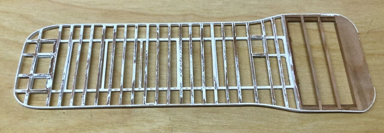
Just a quick Christmas Eve update, since I had a relatively quiet weekend to get a bit more done. Here's the final boiler deck structure, with the edge glued on, and all painted up. I didn't paint the top since it'll be planked over. Top view: Bottom view: Set loosely on the model with a prop at the bow: Though I'd assumed the next step would be planking, I'm realizing I need to build the boiler assembly first, so I can be sure it'll fit nicely underneath. The flues connecting the boiler to the chimneys need to slot into the appropriate gaps in the deck structure, and this will actually help support the deck, giving it more solidity than just the thin support posts. So that's the next step, and honestly it sounds like a nice change of pace from all the framing and planking that this build has mostly consisted of so far. Merry Christmas, Happy Holidays, or whatever other best wish works for you!
- 393 replies
-
- 15
-
-
Hey, great to see you back at work! I hear you on how modeling interacts with bad times; I've paused work a few times for the same reason. Sometimes a hobby is an escape, other times it isn't. Merry Christmas to you too.
-
I've always hated making staircases, I can never get them as even as I like.
- 132 replies
-
- 1
-
-
- King of the Mississippi
- Artesania Latina
- (and 1 more)
-
Great job, that's a beautiful ship and model and I quite enjoyed following along and learning from your build.
-
Siggi, vielen dank for that wonderful photo. I'm clearly a cat person (see username and photo) so that just made my day. And it's nice to be able to attach a face to a builder I respect. I especially enjoying following a build from Germany as my wife still has family there and we both speak passable German. We're hoping to visit them next summer (they live in a small town near Würzburg). Frohe Weinachten!
-
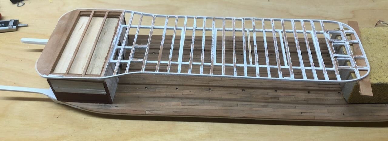
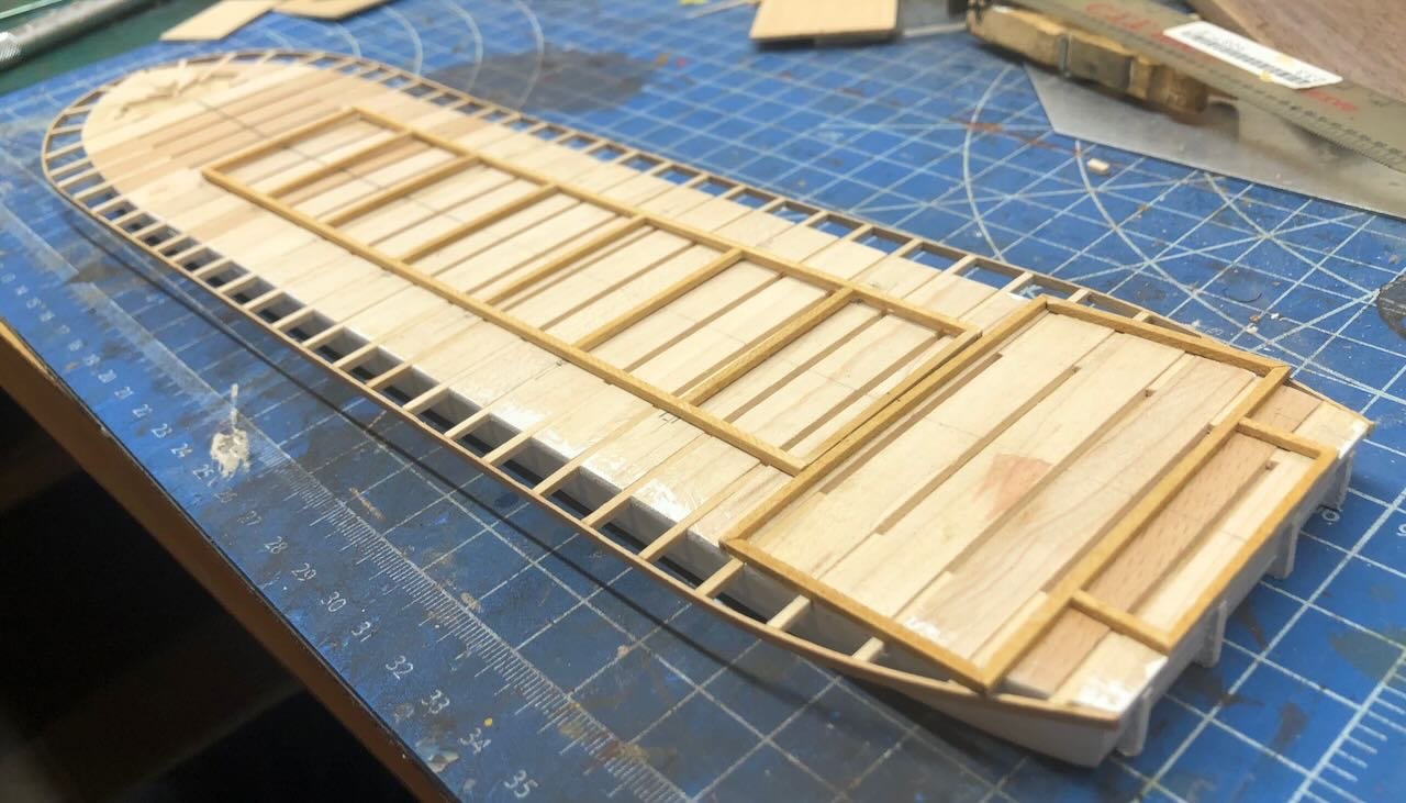
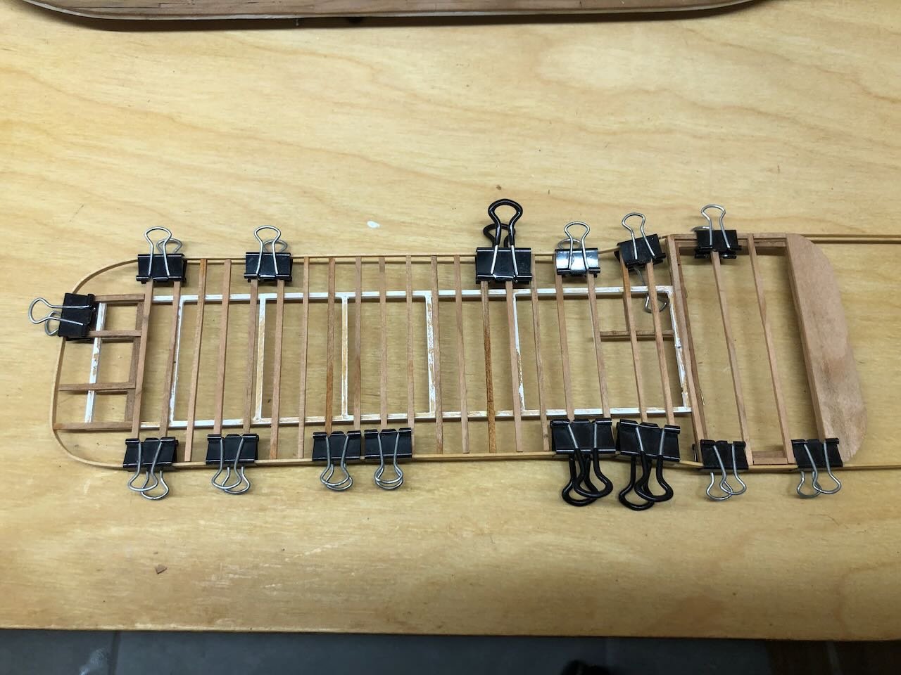
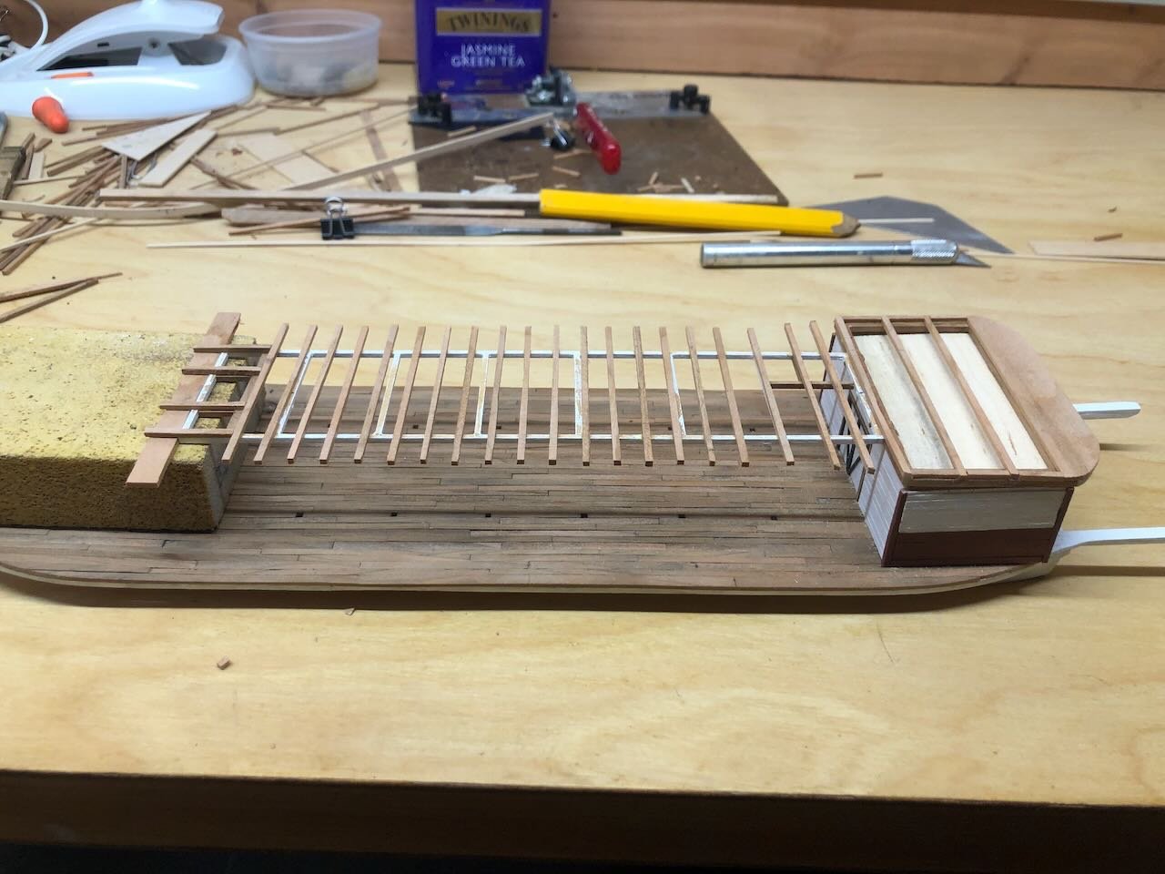
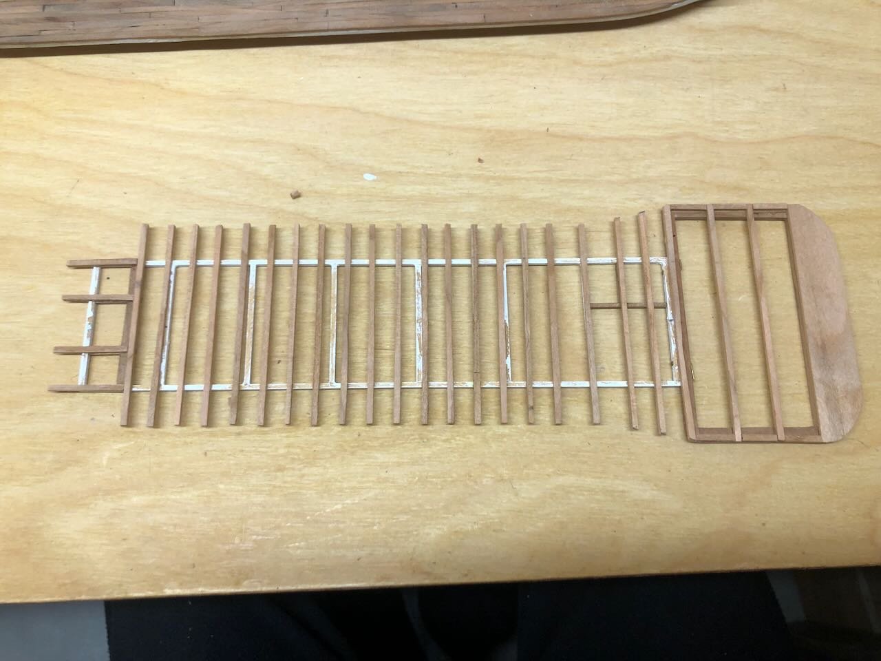
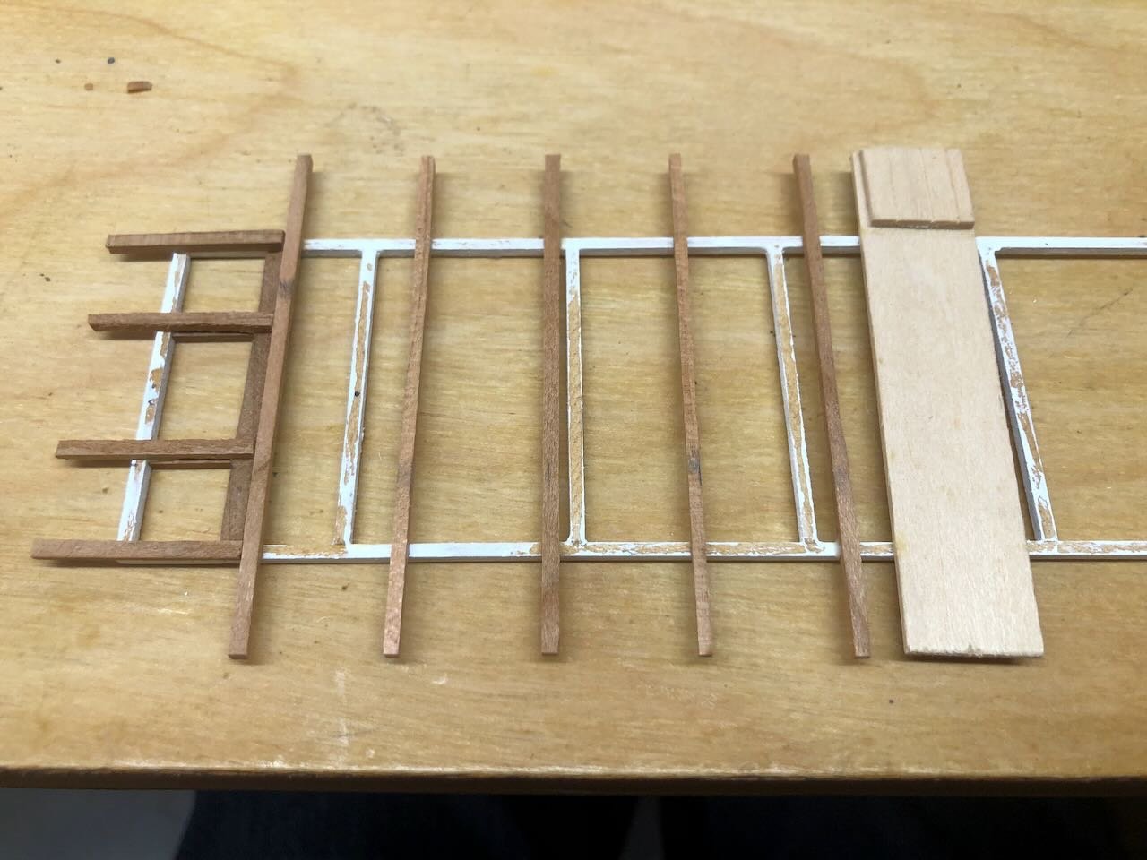
Made some progress this weekend. You may recall that, way back in August, I built the initial frame for the boiler deck: Now it was time to finally start adding to that, now that the engine room structure was done. From what I can see in the original images, especially the one below, there was a rectangular grid that connected to the vertical support posts, topped by a series of parallel beams that actually supported the deck. In other words, a two-layered structure: So I began laying out the cross beams on top my original rectangle, using a simple jig to ensure consistent spacing and centering. Apologies in advance, I seem to have taken very few photos of the next steps: The view above shows the fore end, with special framing where the chimneys will go. Once I had these glued in place, I went back and filled in the gaps with more beams. The photo below also shows the semi-solid sandwich that will glue onto the top of the engine room. If you look closely, you can see that I used two pins to strengthen the joint between the part that sits on the solid engine room, and the part that extends out over the main deck supported only by posts. Here's the completed structure placed loosely as it will be on the model: As a reminder, the holes I left in the main deck planking accept the vertical posts that hold up this boiler deck. A bit flimsy, which is why I'm sticking to my plan of pre-planking the boiler deck before installation. With this done, I soaked some thin wood strips and bent them around the edges of the frame to make the smooth outer rim you see in the original photo: That's where I stand now. Once those strips dry, I'll do a final fitting and gluing. Once I paint this structure white, I think I'm ready to work on planking. For those wondering, all the cross-beams here are on-farm cherry, while the rest of the frame is a mix of that and scrapbox wood. I'm not looking forward to milling lots of thin planking strips, doing so is right at the edge of my skill set with a Byrnes saw. Luckily I have a lot of cherry on hand. Thanks for checking in on this slow, slow progress!
- 393 replies
-
- 18
-
-

-
I agree with Steven, that's a really interesting kit and it'll be fun to see what you do with it. I certainly enjoyed doing a deep research dive and making lots of adjustments/improvements when I built a Viking ship kit a few years ago. Have fun!
-
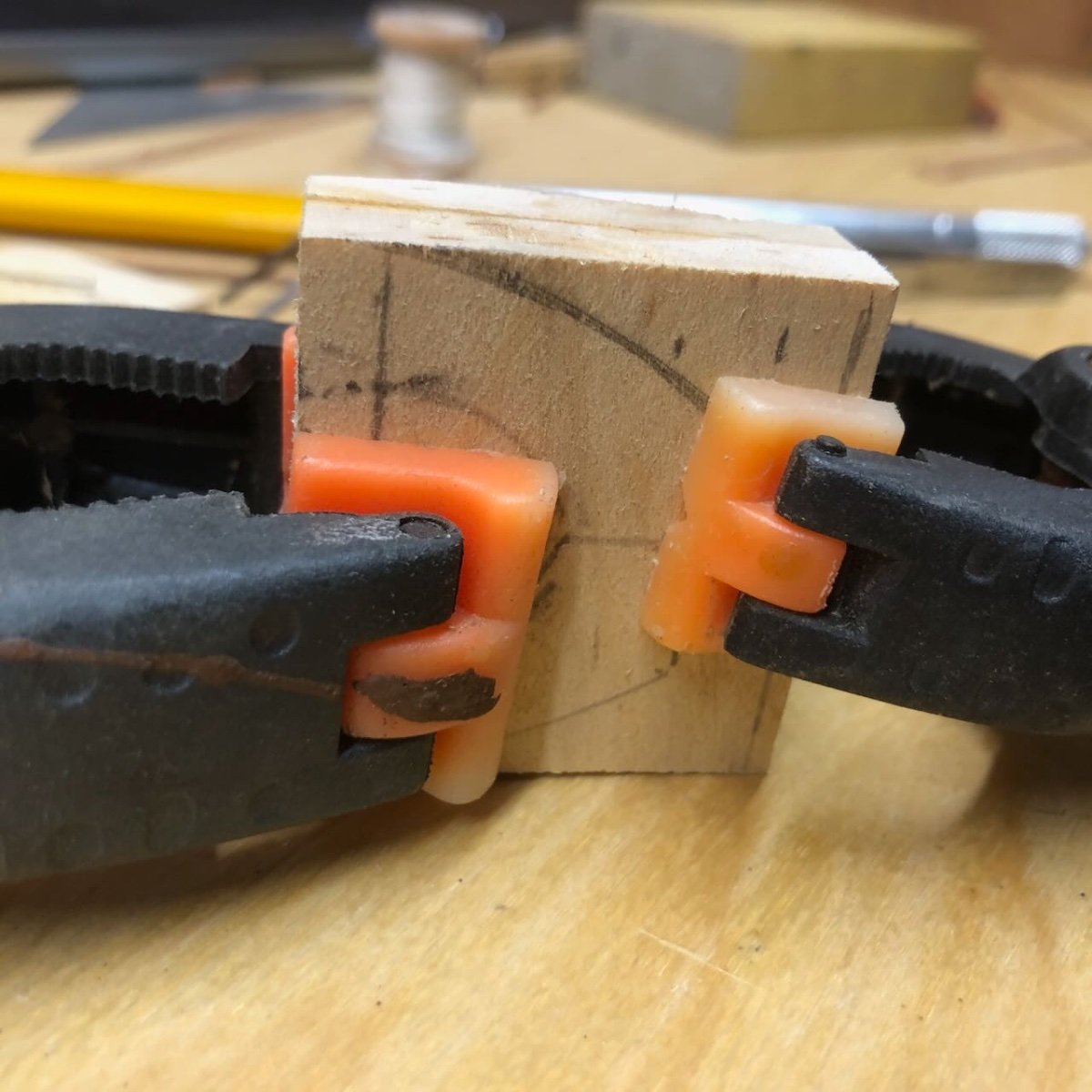
I don't know in what order you're working, but sometimes I've found it helpful to shape the bow end of planks like that first, then work backward to get the rest to fit. That way I know I've got the angle I want at the stem before I put a lot of work into the rest of the plank. It helps avoid the red arrow problem you're showing, where the angle of the front plank seems not quite right. As for marking, something I've also done at times is to mark using a sharp knife, which makes a smaller and more precise line than any marker. You can then gently trace the nick with a sharp pencil to make it more visible, but the pencil tip follows the nick so it doesn't wobble astray. It's an old woodworker technique. It's slightly more fussy but especially good if you're trying to be very exact on measurements, and it doesn't rub off or bleed. Don't know if any of that is helpful. I found this kit challenging as well and it definitely pushed me to improve.
-
If you make paper sails from individual panels, as I did in my method links above, you could build in belly the same way actual sail designers did, by introducing subtle curves to the panels so that, when their edges are joined, they form a curve. And I'd have to disagree that coarse cloth grain is more easily overlooked than improper shape. Proper shape is pretty subtle for an average viewer, whereas coarse cloth is blatantly visible throughout the sail.
-
Keith, let's say it's a mix of intentional and skill/patience limitations. I like building these rough boats where a few flaws in the work doesn't distract the way they would in, say, a pristine Royal Navy frigate. Not intentionally being sloppy, but the natural output of my comfort zone tends to produce a reasonable outcome for this sort of model!
-
Great explanation, thanks!