Cathead
-
Posts
3,522 -
Joined
-
Last visited
Content Type
Profiles
Forums
Gallery
Events
Everything posted by Cathead
-
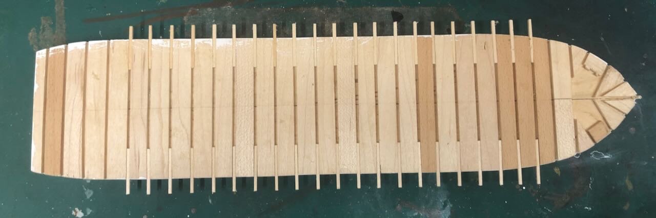
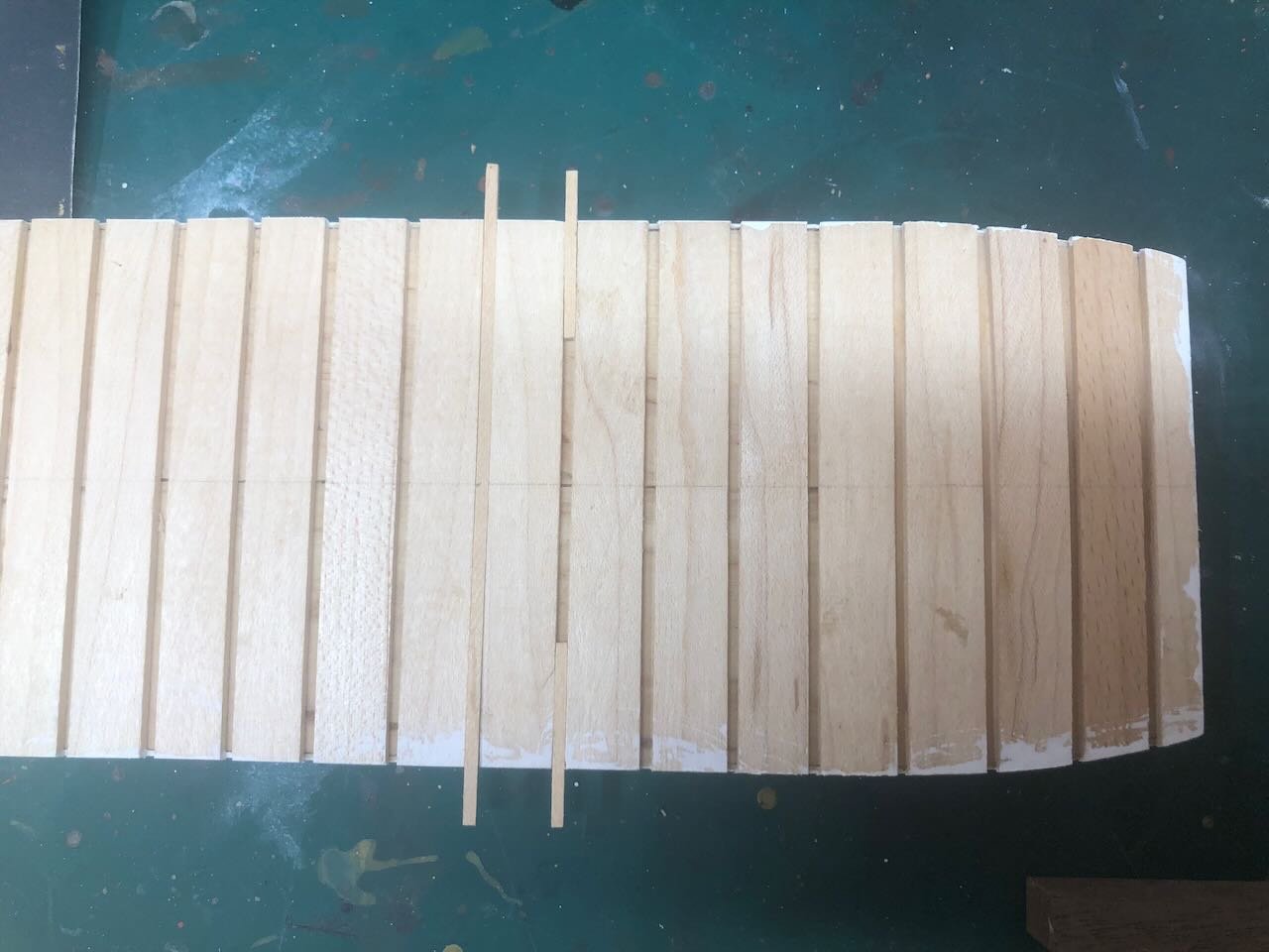
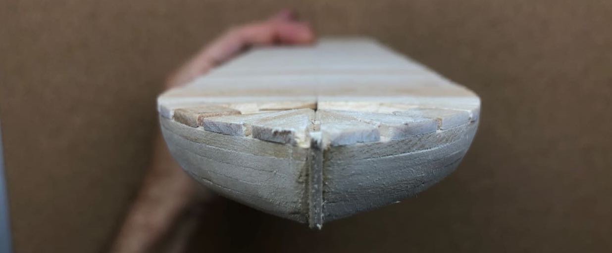
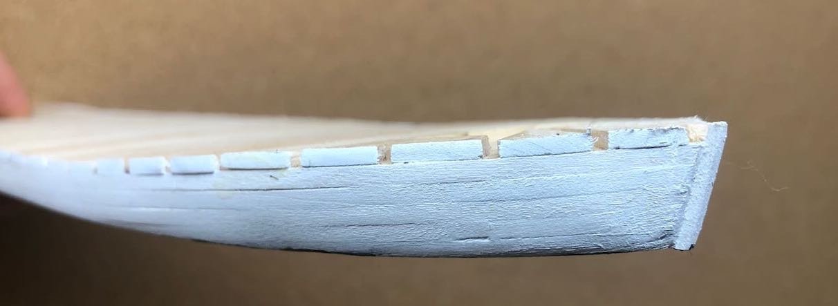
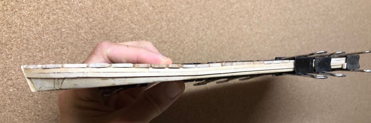
 OK, wisdom of the crowd wins. I went ahead and cut/glued most of the guard beams as short segments, doing all those that form a straight edge. To fore and aft, their length will change to support curves at bow and stern, so I'll do those once these dry so they form a solid base for forming the curve. If this doesn't end up being the right decision, it's now all your fault! You might notice that, at the bow, I kept the line straight beyond where the hull starts to bend inward. That's because the shape of the deck should form a rounder curve into the bow, not a sharp point as in the hull. This creates an especially broad overhang on either forward quarter, which you can see especially well in the photo below. I also finally got around to printing out some of my favorite reference photos and pinning them to the tack boards above my new workspace. So here's the current hull with its inspiration. Another evening this week, I should be able to finish the rest of these beams. Thanks for reading, liking, and commenting!
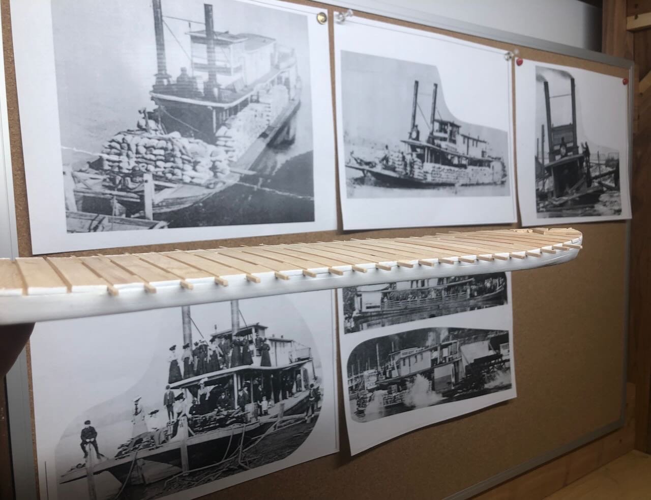
- 393 replies
-
- 14
-

-
I found, when rigging, that it added quite a bit of enjoyment to work at understanding how rigging actually worked in general, so that I understood what I was setting up and just not assembling a mess of lines. Doing so also helped me catch what I felt were a few errors in rigging plans, and make changes that made sense to me in terms of how the lines would actually function.
- 25 replies
-
- 1
-
-
- Harriet Lane
- Model Shipways
- (and 1 more)
-
Timber-framed outdoor kitchen - Cathead - 1:1 scale
Cathead replied to Cathead's topic in Non-ship/categorised builds
Oh, I took it as a joke and meant my reply to be lighthearted as well. Apologies if that wasn't clear. He fishes Bristol Bay, brings it back frozen. Sells most of his catch word of mouth across Missouri, delivering around the state in the fall. I agree, unless you live by the dock, buy frozen in general. Especially with modern flash-freezing, I was talking to a Gulf shrimp fisherman years ago and he was very happy with the quality preservation modern freezing could achieve. -
Timber-framed outdoor kitchen - Cathead - 1:1 scale
Cathead replied to Cathead's topic in Non-ship/categorised builds
As a geologist, I have no argument with climate change as a real process. But sourcing both the meat and wood on-farm as part of our forest improvement work buys me all the carbon credits I could want! OK, I didn't get the salmon on-farm. But I did get it directly from a Missouri resident I know who teaches here in the winter and runs an Alaska salmon boat in the summer. We usually buy about 30 lb from him every fall when he comes back south. Far higher quality than the store. -
Timber-framed outdoor kitchen - Cathead - 1:1 scale
Cathead replied to Cathead's topic in Non-ship/categorised builds
If I didn't live so far away from most of you, you'd all be eating me out of house and home claiming you were just here to see my models! Truth.- 131 replies
-
- 10
-
-

-
Timber-framed outdoor kitchen - Cathead - 1:1 scale
Cathead replied to Cathead's topic in Non-ship/categorised builds
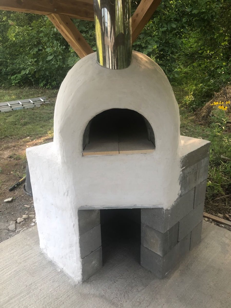
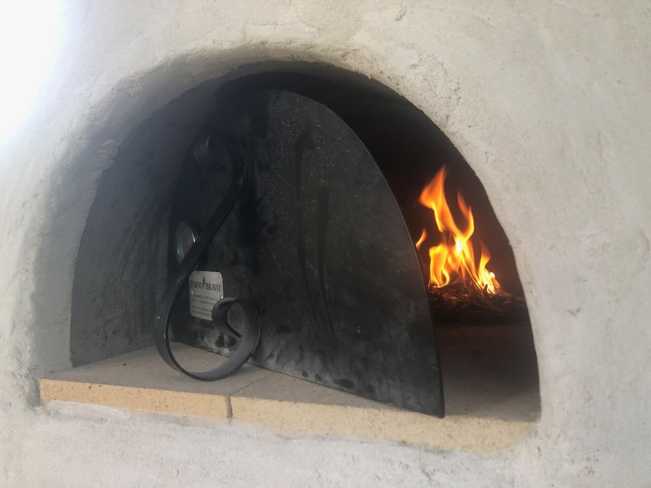
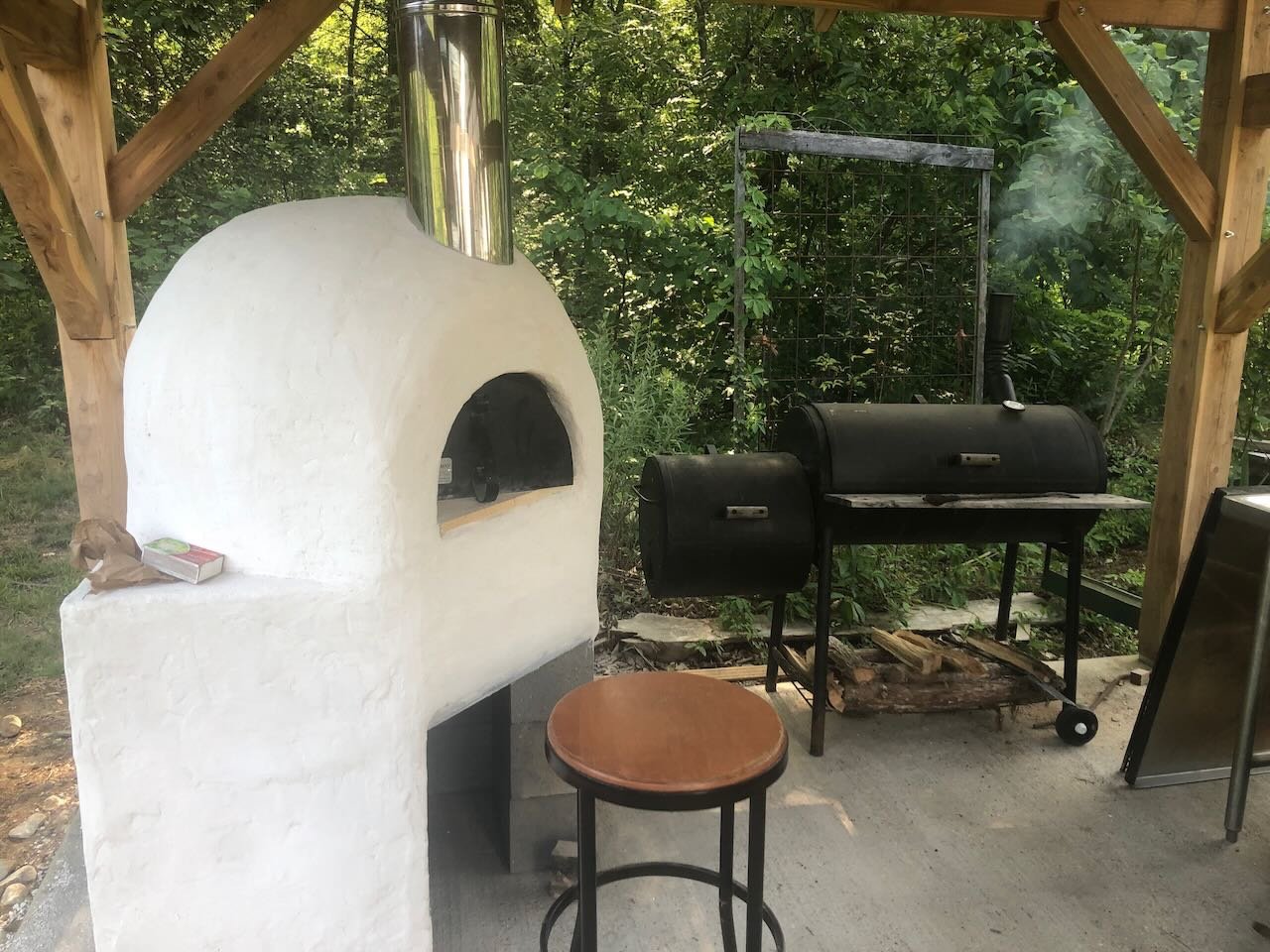
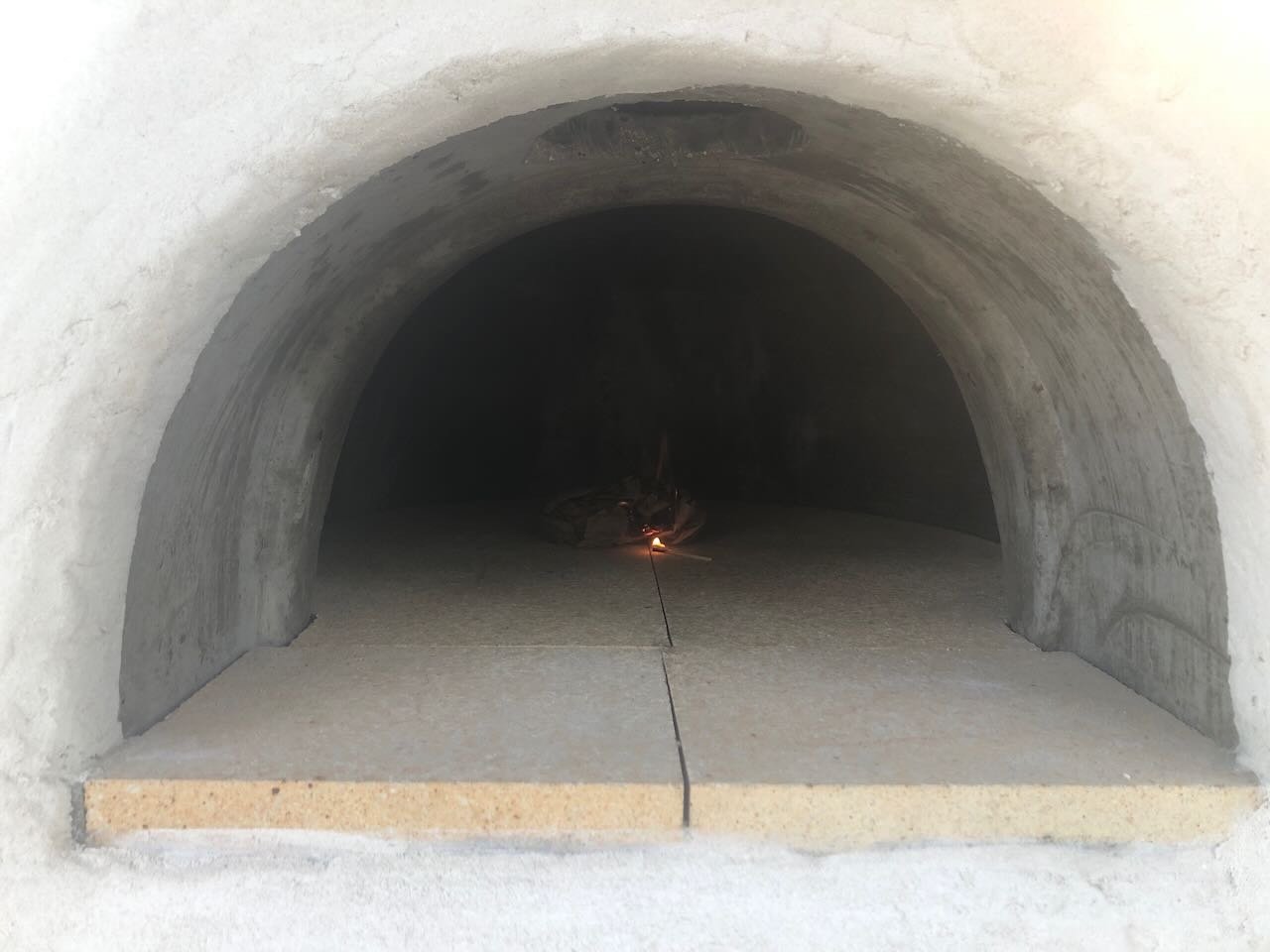
And the oven structure is done! Here it is with the final coat of stucco: If you're wondering about the odd pattern on the base (just one base wall with stucco), there's a reason. We eventually intend to cover the base and dome with creek rock held in place by mortar. So there's no need to finish the concrete block base with anything for now. The dome needs its full stucco coats to retain heat and be usable. The reason there's a stucco coat on just that one base wall is that we'll be building a large firebrick grill right up against that wall, so it won't be getting the creek rock treatment, so we decided to seal it in with stucco instead. It'll be all but hidden when the decorative work is done. But now it's time to start building fires. The idea here is that there's still a lot of moisture in the concrete dome and surrounding stucco, and that needs to be carefully driven out to fully cure the oven for high-temperature cooking. So the official process is to start by building small fires in the oven, keeping the initial internal temperature below 300ºF, and then over the course of a week slowly build bigger and bigger fires. If one builds fires too hot, too fast, the danger is that the moisture isn't gently driven out of the dome, but instead steams off, causing cracking or other structural damage. By next weekend, if all goes well, we should be able to cook in it. So we're spending today maintaining a small kindling fire within the dome. Here's the first-ever flicker of flame within, followed by a typical view of the first day's curing fire. I can absolutely see the value of purchasing a professional dome rather than trying to design one ourselves. Despite the very tall chimney (something like 10'), the oven drafts beautifully, drawing in air low over the firebrick and spiraling the smoke and heat up into the chimney. It would be very easy for a poor design to just spit the smoke back out the front arch, choking the fire and the user, but this works exactly as designed. Since we have to pay close attention to the fire today, to keep it going but not too hot, we doubled down on kitchen duty and fired up the adjacent smoker, where two venison loins (about 5.5 lb total) and a couple long salmon fillets are gently smoking. This is an old-fashioned barrel smoker that I run with hickory, oak, and fruitwood cut and cured on-farm. No charcoal, gas, or other fancy stuff. Just carefully managed wood and smoke. Unfortunately, this coming week is forecast to be our hottest yet for the summer, highs near 100ºF from Tuesday through at least Saturday. Not the ideal conditions to manage careful fires, but that's life. One great value of working from home is that it's so much easier to manage projects like this. Hopefully this all goes well and we have an uncracked and cooking-ready oven by next weekend! Thanks for reading.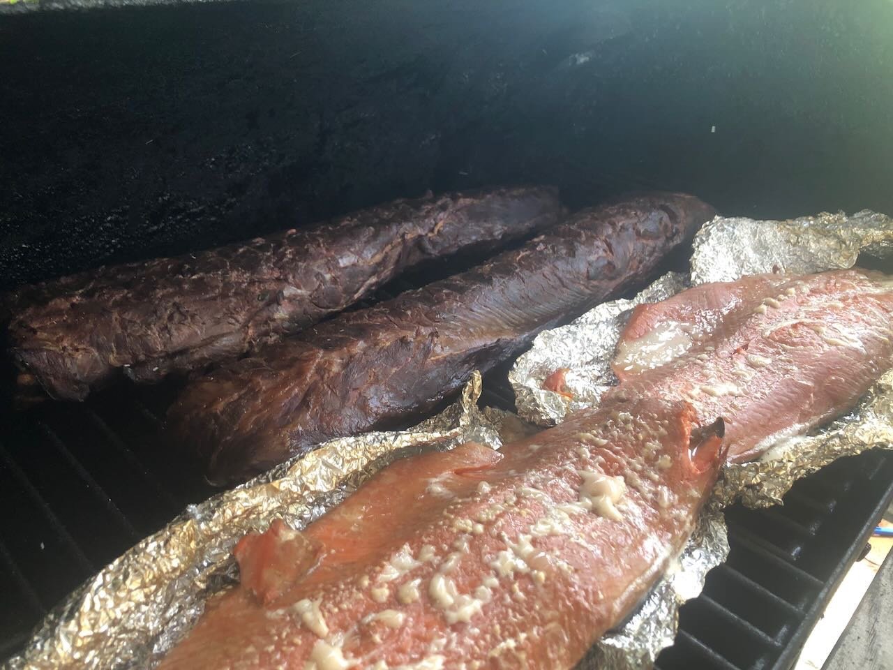

- 131 replies
-
- 16
-
-

-
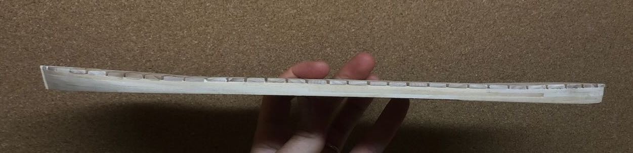
The only downside I thought of overnight, is that I'll be mounting various small vertical posts along the deck and was planning on using small pins to help anchor them. Where those happen to go through one of those slots, there won't be much support. I guess I could just use long enough pins to ensure they go down into the hull proper. Also, technically I'm still using wood from my scrap box for these beams. Once I start on the superstructure I'll be making my own wood again.
-
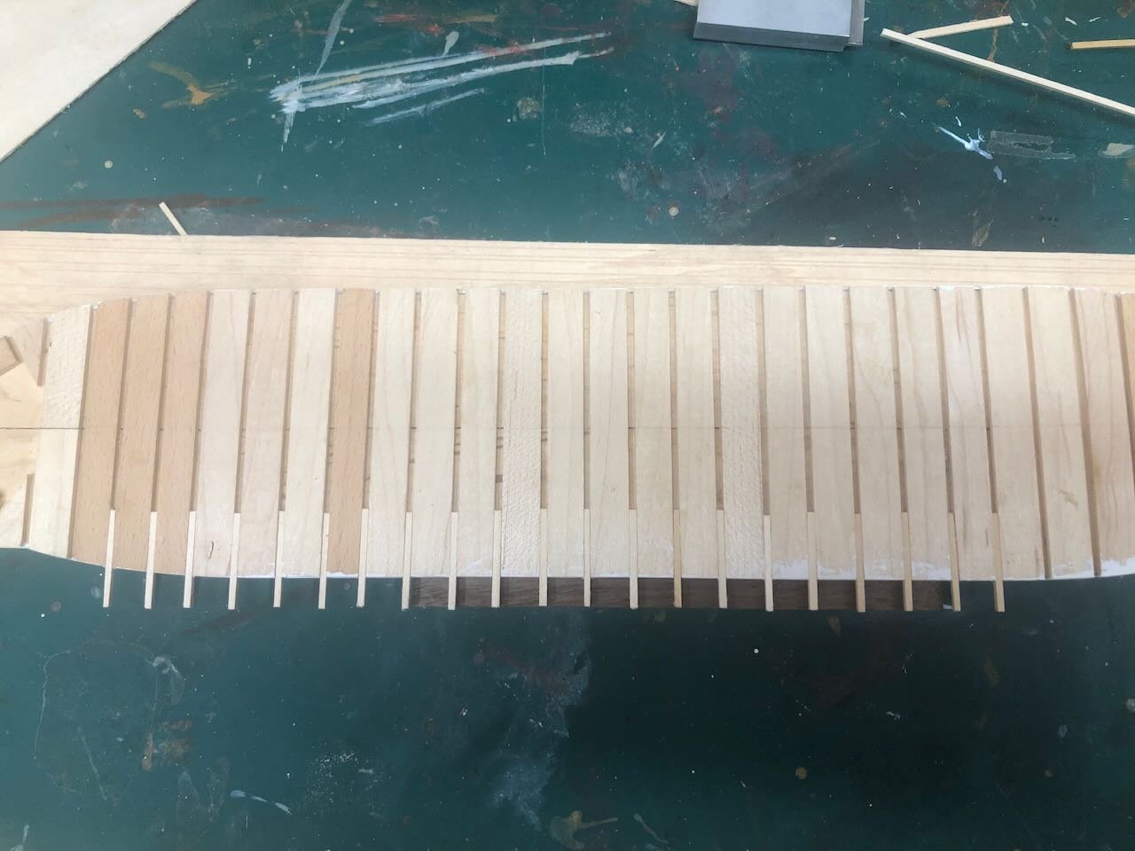
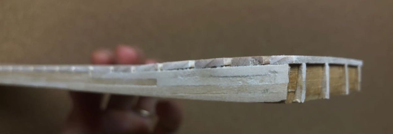
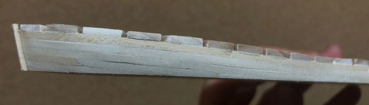
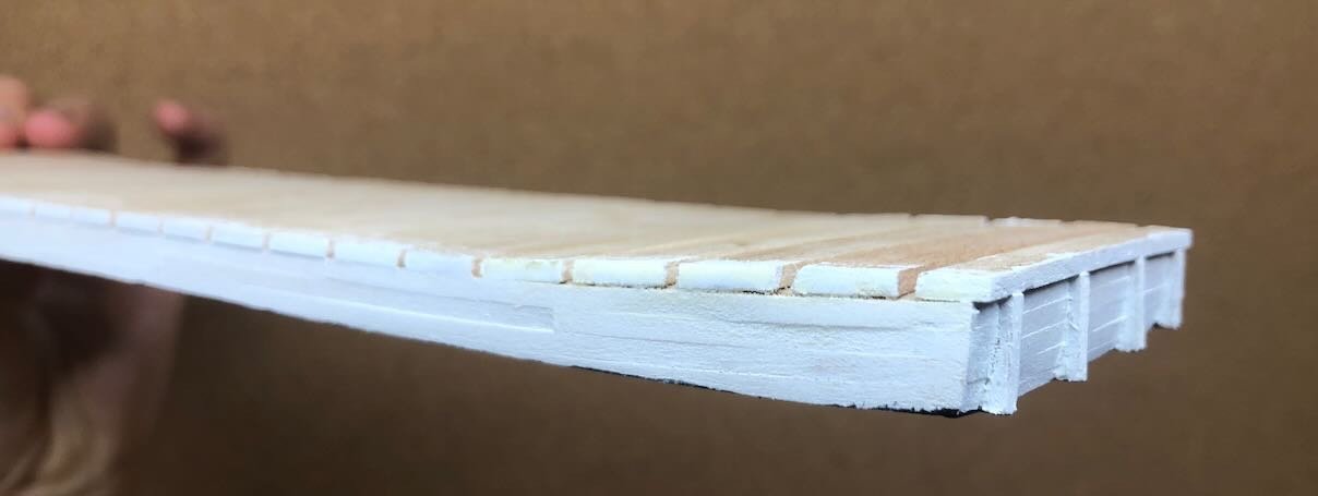
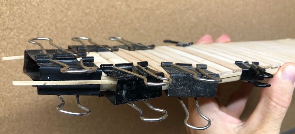
I've started test-fitting the beams that support the guards. I'd initially planned to use single beams run all the way across the hull, set into the slots I laid out. But I got to thinking, does it need to be that way? It'd save a lot of wood to leave the center of each slot open and use a shorter piece on each side. The photo below shows both options: I'm thinking the right-hand option makes perfect sense. The deck planking will be plenty well supported; is there any need to actually fill all that middle space? Here's one side of the guard beams (mostly) test-fit this way. Notice the spacer block I'm using to get the ends parallel. What do you all think?
- 393 replies
-
- 14
-
-
Barncave Shipyard by mbp521 - Scale 1:1
Cathead replied to mbp521's topic in Non-ship/categorised builds
Fantastic work. Getting anyone DMing you about custom workshop jobs? -
Yep, that's why I'm not worried too much about minor flaws in artisanship. I want this vessel to look cobbled together, well-used, and very local.
-
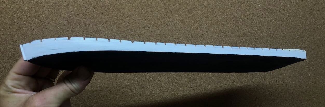
Planking is finished. Took many small bits of time, a few planks here and there in the evening, letting the glue set and coming back to do another. Once I had them all on I sanded things reasonably smooth, including knocking back the filler pieces to match the edge of the planking. The hardest bits were the parts where the planks dip past the waterline at the bow and stern. For these, I just glued full planks past the bottom of the hull, then carefully shaved them down flush once the glue dried. Next I gave a first coat of white paint. I plan to sand this down again and reapply another coat. Paint tends to bring out small imperfections in the planking, but on the other hand, this was a rough-built boat and these may actually give it that feel. A too-perfect hull would look awfully...naval. And again, most of this will be in the shadow of the overhanging guards. I also painted the bottom black, to help create a shadow effect underneath when viewed from the side, hiding any slight unevenness of the hull bottom or sides. This photo has a messed-up color balance because of the white/black contrast but you get the idea. Next step is a light sanding, another coat of thin paint, and another sanding. When I'm happy with it, I'll start adding the guard/deck beams. Thanks for reading!
- 393 replies
-
- 14
-
-
Best wishes and glad to see you back at work!
-
I think every one of my models has some of my blood in it. I've decided that's a good thing.
-
Hmm...I think my concern is that cosmetics and house-cleaning products aren't meant to have a long life when applied high-value surfaces. Both initially stay in tight containers, then tend to get washed off pretty quickly after application. Unless you know any women who keep their makeup on for 30 years without taking a shower?
- 208 replies
-
- 1
-
-
- kitbashing
- Woodcarving
- (and 4 more)
-
Timber-framed outdoor kitchen - Cathead - 1:1 scale
Cathead replied to Cathead's topic in Non-ship/categorised builds
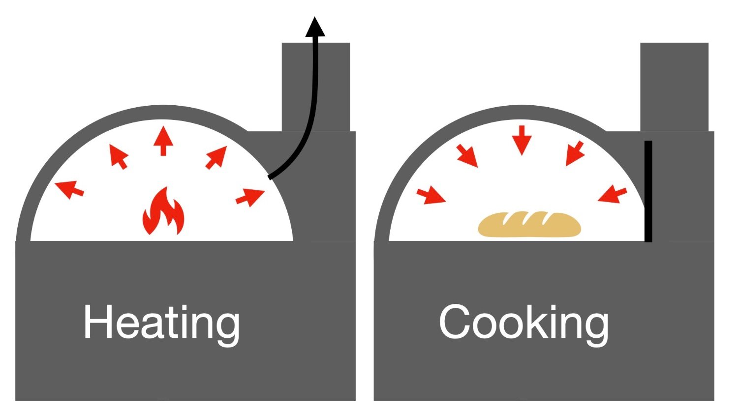
To help clarify Roger's excellent question, I whipped up a diagram of how ovens like this work. On the left, you heat the oven with an internal fire. The masonry dome and firebrick floor absorb that heat, while the chimney carries away the smoke. On the right, once the interior is heated, you remove or push back the coals, close off the chimney with a metal door, and whatever food you place inside cooks from radiative heat. Ideally, an oven like this should hold temperature for at least 6-8 hours, declining very slowly. So for example, you start with pizza at >700°F, shift to loaves of bread as it declines into the 450-500 range, then replace that with low/slow cooking items like a venison roast or a big pan of mixed root vegetables. When the oven gets low enough, you put the next round of firewood in so it completely dries in the remaining ambient heat, ready for the next round another day. So with one firing using a small armload of wood, you can cook all day and produce large quantities of food for the rest of the week. Far more efficient than an electric/gas oven and the heat stays out of the house. If you visit a restaurant that uses these, like a nice pizza place, you'll generally see a small fire burning in their oven even as they cook. That's because they need to maintain the same temperature all day. But in a home oven where I don't have to produce pizza on demand from 11 am to 10 pm, a single firing will suffice if the cooking plan is set up to take advantage. And it doesn't always have to be that way, the oven is efficient enough that just firing it for a pizza lunch remains sensible. Wood is an inexhaustible natural resource here and in the natural course of our timber management for forest health we produce all the firewood we could possibly want for home heating and cooking.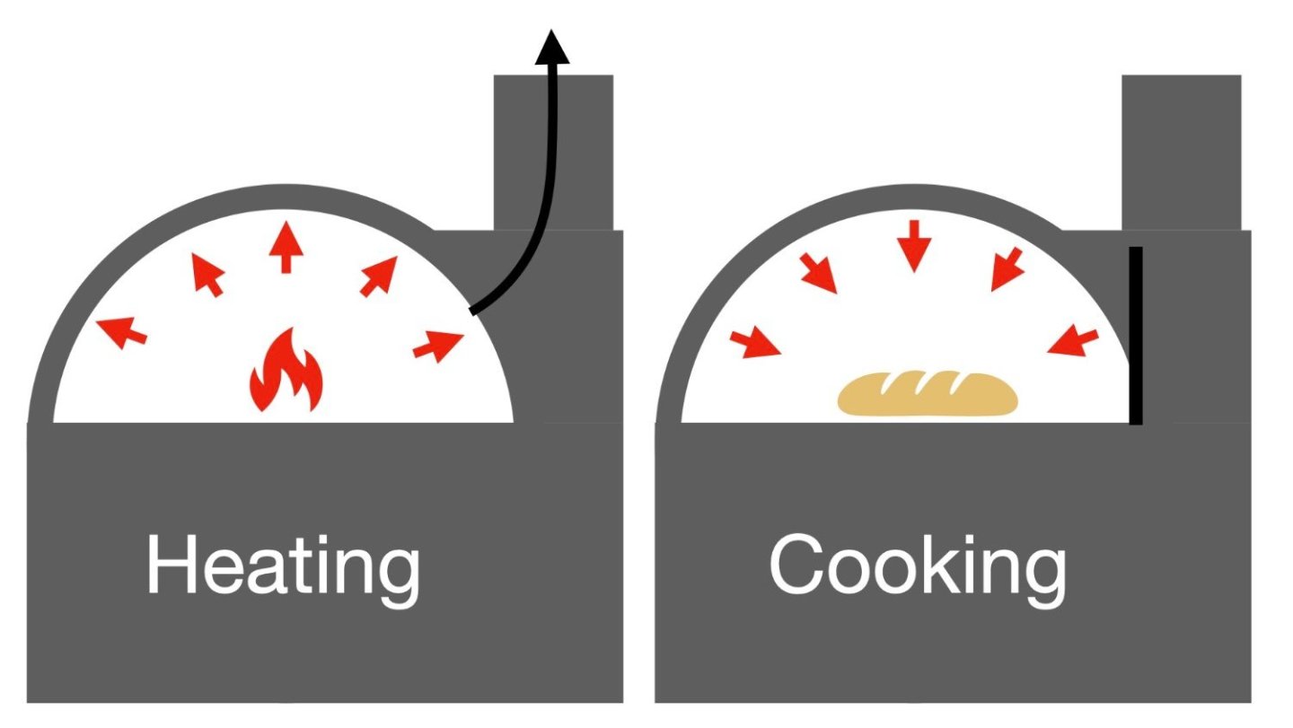
-
Happy birthday and great work on the blocks. I enjoy seeing how folks improve on kits. I wonder, on the potato sails, whether there's any long-term concerns about biological effects, like attraction to insects or mold/fungus? The visual effect is lovely.
- 208 replies
-
- 4
-
-
- kitbashing
- Woodcarving
- (and 4 more)
-
Timber-framed outdoor kitchen - Cathead - 1:1 scale
Cathead replied to Cathead's topic in Non-ship/categorised builds
Our biggest hangup on the true DIY wasn't the shape, we figured we could build a decent form one way or another. It was the nature of the dome material. This has to be right, as it takes the brunt of the fire's heat, and if it cracks later on you've got a deep problem (pun intended). Plus, we found various DIYers referring to have some material spalling off their dome on the inside, and the first time you crack a tooth on a piece of sand or something you've just paid for a professional dome but it went to your dentist instead. The dome we ordered is made from a high-end proprietary material and designed by experts, they sell these to private and commercial users all over the world. This isn't a part where it's easy to just start over if you screw something up. So we felt a lot better about the quality and reliability of that particular piece, knowing (believing?) that we could do the rest ourselves. -
Timber-framed outdoor kitchen - Cathead - 1:1 scale
Cathead replied to Cathead's topic in Non-ship/categorised builds
Fair question. The fire is built within the dome, heating it internally. You don't cook directly with the flames or coals (like a grill) but with the radiative heat retained in the dome. The masonry and insulation hold the heat for many hours, so once you've fired it, you can roast/bake/cook for a very long time. Potentially 8 hours or more. The rounded shape helps ensure even circulation and heating. If you build a hot fire at one end and put food in right away, you'd get very uneven cooking. Ovens have been used this way for thousands of years in various cultures. Some cultures also built barrel vaulted ovens, but these are harder to cook evenly in because the heat doesn't circulate right. I know, we built a homemade version as a test case years ago and that's what happened. Barrel vaults are so much easier to make, but ours proved to us that the firing and cooking wasn't even enough and we wanted a true dome. Which is one reason we went with a kit instead of a true DIY because a DIY true dome is a lot harder to engineer, so we compromised between true DIY and a completely premade oven, which would be both far more expensive and nowhere near as satisfying. The chimney carries away the heat and draft from the active fire, but once it's time to bake/roast, you close the dome off from the chimney with the metal door seen in my photo above, retaining the heat within. At that point no more air or draft is needed because the fire isn't needed. To answer a related question that gets asked a lot, the space beneath the dome is not directly related to firing or baking (i.e. the fire does not get built down there). It's just empty space created by the foundation, no point in making that a solid mass. The most common use for it is storing firewood. The traditional cycle is that, once the oven has started to cool and you're done using it, the next round of firewood is placed within the dome, where the residual heat cures it extra-dry and it's ready to go. The space down below holds many rounds worth of wood out of the rain and so forth. -
Planking has begun. It took me a little while to figure out how to clamp planks to this solid hull. I'm more used to bulkhead construction where clamping is easy. I finally figured out that some large binder clips would engulf the entire hull, pressing down on the planks in the middle. I'm doing both sides simultaneously. It's sporadic; cut/glue/clamp a couple planks, let them dry a while, come back and do a few more. As photos tend to do, this one below is bringing out a few minors faults, like a bit of gap at the most extreme curve in the bow, and the somewhat angular transition from flat center deck to the rise of the bow, despite my attempts to sand that to a smoother curve. I don't find these as obvious in person and they'll be partly hidden anyway by a combination of paint and the overhanging guards. Overall this is going smoothly. Got a busy day today but will probably be able to get a few more on between other tasks. Thanks for reading!
- 393 replies
-
- 12
-
-
Absolutely, but this speaks more to the quality of the manufacturer/kit than to the style of the kit. You'll get a more accurate hull from a manufacturer who produces a well designed/produced POB or solid-hull kit, and you'll get a less accurate hull from a manufacturer who produces a sloppy version of either. And in either case the modeler can always improve a sloppy kit with enough work. Everyone's personal experience is certainly valid. Mine has been that I find POB easier, more intuitive, more enjoyable, and more educational than solid-hull.
-
Timber-framed outdoor kitchen - Cathead - 1:1 scale
Cathead replied to Cathead's topic in Non-ship/categorised builds
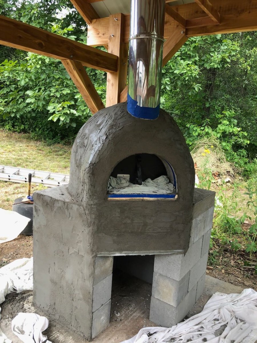
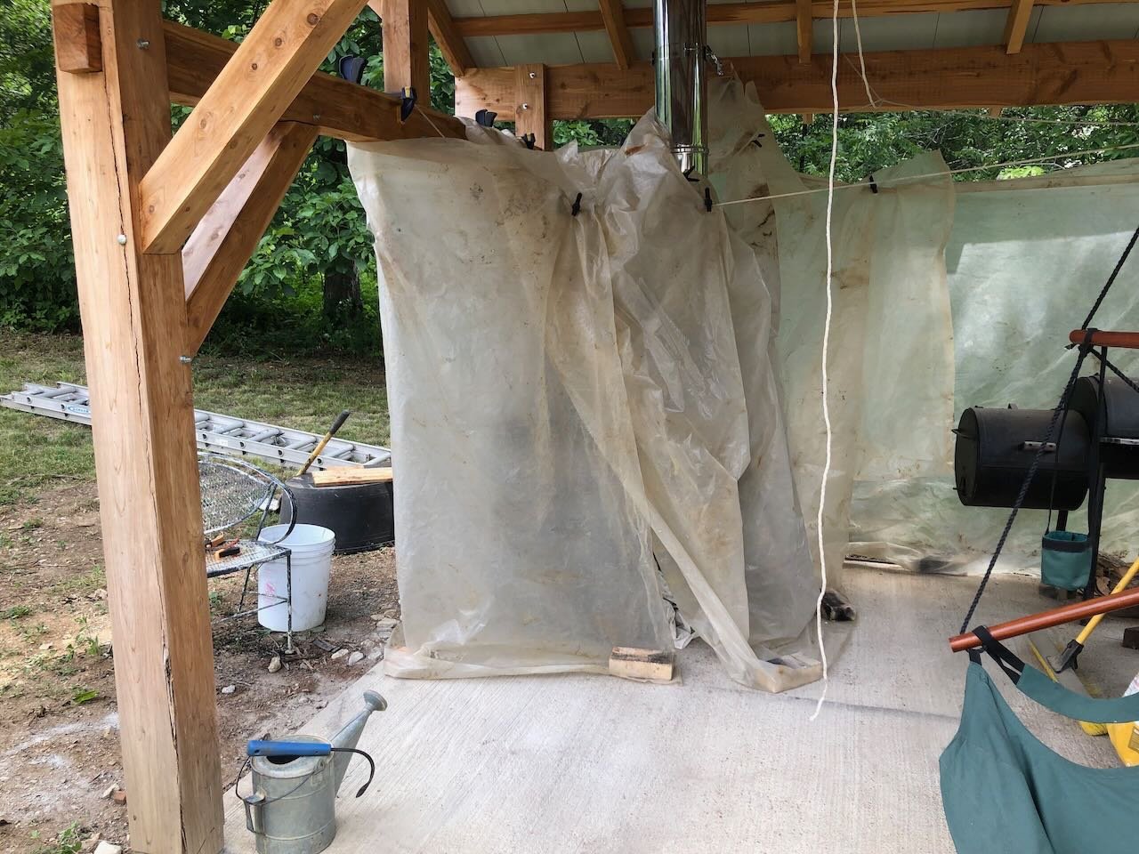
Back on track, here's the first round of stucco freshly laid. We've been keeping it misted when we can, and wrapped it more thoroughly with plastic to help maintain humid curing conditions. Here it is initially cured this morning. The next round won't happen until Monday, we'll need to take some time away from work to do it, can't get to it today. Looking like a proper oven, though!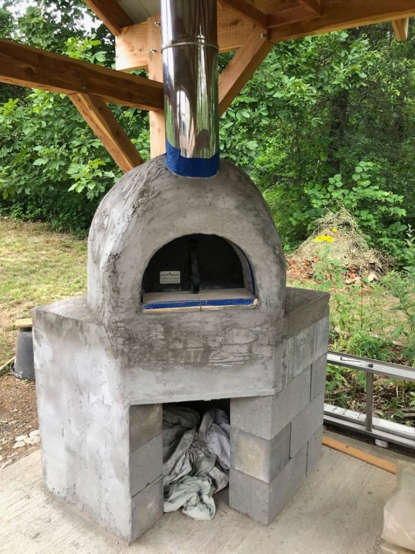

-
Speaking just for myself, and for the sake of argument, I'd generally rather plank a bulkhead hull than deal with a rough-cut solid hull. To me, if the bulkheads are reasonably accurate, the natural run of the planks creates a reasonable hull shape. If the planking isn't meant to be seen, then it doesn't have to be perfect and is easy to finish using filler. In comparison, getting a solid hull right means manually getting every inch of the hull shape right, which the natural curve of planking does for you on a bulkhead model. It also strikes me as easer for scratchbuilding, since you can take station lines off a plan and, again, let the planks do the rest, rather than trying to manage every square inch of a solid wood surface. And while rough planking isn't the same as "how the real thing was built", it's a lot closer than sanding down a block of wood! Even my earliest attempts at planking taught me quite a bit about the geometry and physics of bending wood, inspiring an interest to know more. Whereas shaping a solid hull feels more like making a Dutch shoe. I can easily see how things might be different for more modern vessels with, as Roger says, complex hull shapes that don't have the simple lines of a traditional wooden sailing vessel. Interesting economic perspective from Mr. BlueJacket, thank you.