Cathead
-
Posts
3,522 -
Joined
-
Last visited
Content Type
Profiles
Forums
Gallery
Events
Everything posted by Cathead
-
 That looks so good!
 -
Roger, also check out Northeastern Scale Lumber. They produce a wide variety of scale lumber and scored sheets that simulate various planking and siding styles. Lots of people in model railroading use products like this.
-
Old eyes and shakey hands needs some advice
Cathead replied to David Rice's topic in Wood ship model kits
David, it's not a question of wanting to argue, it's a question of making sure we provide accurate guidance to modelers. I think you're overstating the case by saying that no can can photograph or create artwork that includes any Native American imagery, and can muster more evidence for this, but will drop it, especially as it's off-topic for this discussion. The last I'll say is that I'm very familiar with the legal situation regarding bird feathers as a long-time birder and conservationist. Here is a resource from the US Fish and Wildlife Service on feather possession law: https://www.fws.gov/lab/featheratlas/feathers-and-the-law.php#:~:text=The possession of feathers and,Bird Treaty Act (MBTA). Again, the law was written (and is enforced) to protect bird populations. The tribal rights exemption is quite proper, but it's not inherently a question of tribal law. And it's not complicated: no ownership of bird feathers unless you qualify as Native American (if you don't know, you don't qualify) or unless you're a hunter in possession of a legal game species (like a duck). -
Old eyes and shakey hands needs some advice
Cathead replied to David Rice's topic in Wood ship model kits
David, with respect, I think you're overstating the situation. Tribal laws can certainly vary, and I don't know what Tlingit and Haida Nation policy is specifically, but there's no blanket national prohibition on photographing or otherwise reproducing native arts and crafts. For example, the Navajo Nation requires permits for commercial photography (anything that will be sold or otherwise distributed commercially) but welcomes personal photography as part of their essential tourism industry. Such photography should always be done respectfully, and ideally with personal permission, but there's no Federal law outright forbidding it. I'd guess that you got in trouble, not necessarily for taking the photo/video, but for letting it be placed on TV, because that became a commercial use situation. As for the eagle feathers, that's not rooted in tribal law, but conservation law. Possession of any feathers from native North American birds is illegal, a rule rooted in conservation efforts to stop the harvest and trade in feathers that was decimating bird populations. There is an exception for Native Americans in cases where specific feathers (like those of the Bald Eagle) have cultural/spiritual value, but the basic law has nothing to do with tribal rights. -
Old eyes and shakey hands needs some advice
Cathead replied to David Rice's topic in Wood ship model kits
David, I was under the impression that such restrictions only applied to sales and implied provenance, as described on this Department of the Interior site: The wording here seems to clearly refer to arts and crafts for sale that are representing themselves as Indian-made, rather than broader artistic themes that simply incorporate Indian imagery as a natural part of the art. For example, under your description, a historical painter couldn't include any imagery of Indian jewelry, basketry, or clothing if they are not themselves native; same for a museum diorama builder; and that hardly seems to be the legal situation. To me, it seems that a representative scale model of a vessel of native design is quite different from a model actually built or carved in a specific native style and being passed off as native-made. And even then it appears to be primarily a question of marketing, not production. When I was in college (post-1990, so post- Indian Arts and Crafts Act of 1990), I took a course in Navajo weaving as a balance to my heavier double-major coursework in science and foreign language. Navajo tribal rules at that time (as they were presented to us students) were that you couldn't teach their weaving unless you had been trained directly by a Navajo, but that there was nothing wrong with making your own Navajo-style weavings for your own use as long as you didn't try to sell them or otherwise pass them off as authentic. It seems to me that the same sensible approach would apply to model building. Can you provide further insights into your belief that native designs or imagery can't be legally used in any context at all? -
Well, my model's imperfections don't threaten to take me and my livelihood to the bottom of the river!
-
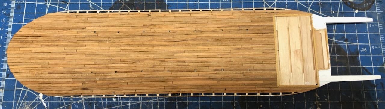
Main deck planking is almost done! One more run to go on either side, but I don't know when I'll get to it as I need to cut more planking to do this. I've learned some lessons doing this and cursed myself for some (in hindsight) fairly stupid decisions. I'll also need to improve my plank-milling skills moving forward as this deck is more forgiving than the rest of the model will be. But I'll write more about that when this deck is actually done. I just figured you all should get a progress report as it may be a bit longer before another, I have a busy stretch coming up. Thanks for sticking around...
- 393 replies
-
- 21
-

-
This looks so cool!
-
Old eyes and shakey hands needs some advice
Cathead replied to David Rice's topic in Wood ship model kits
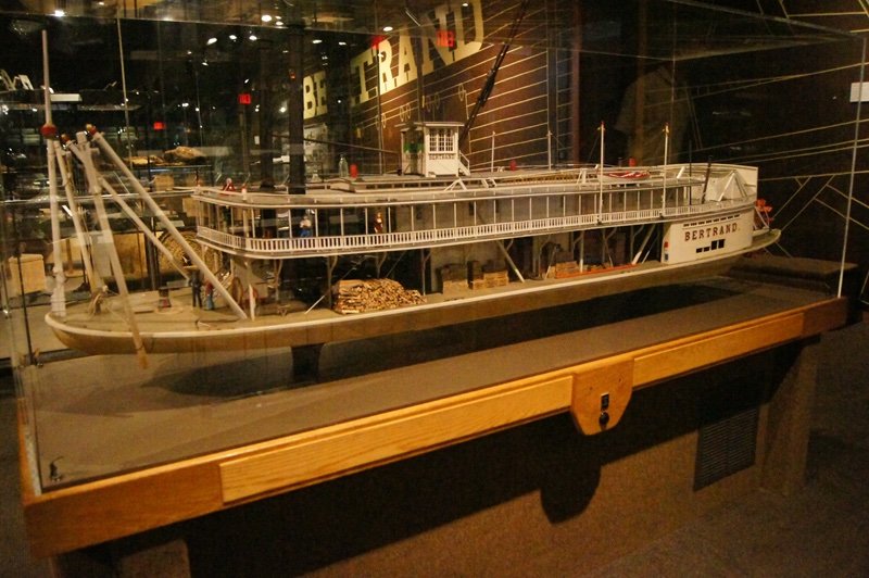
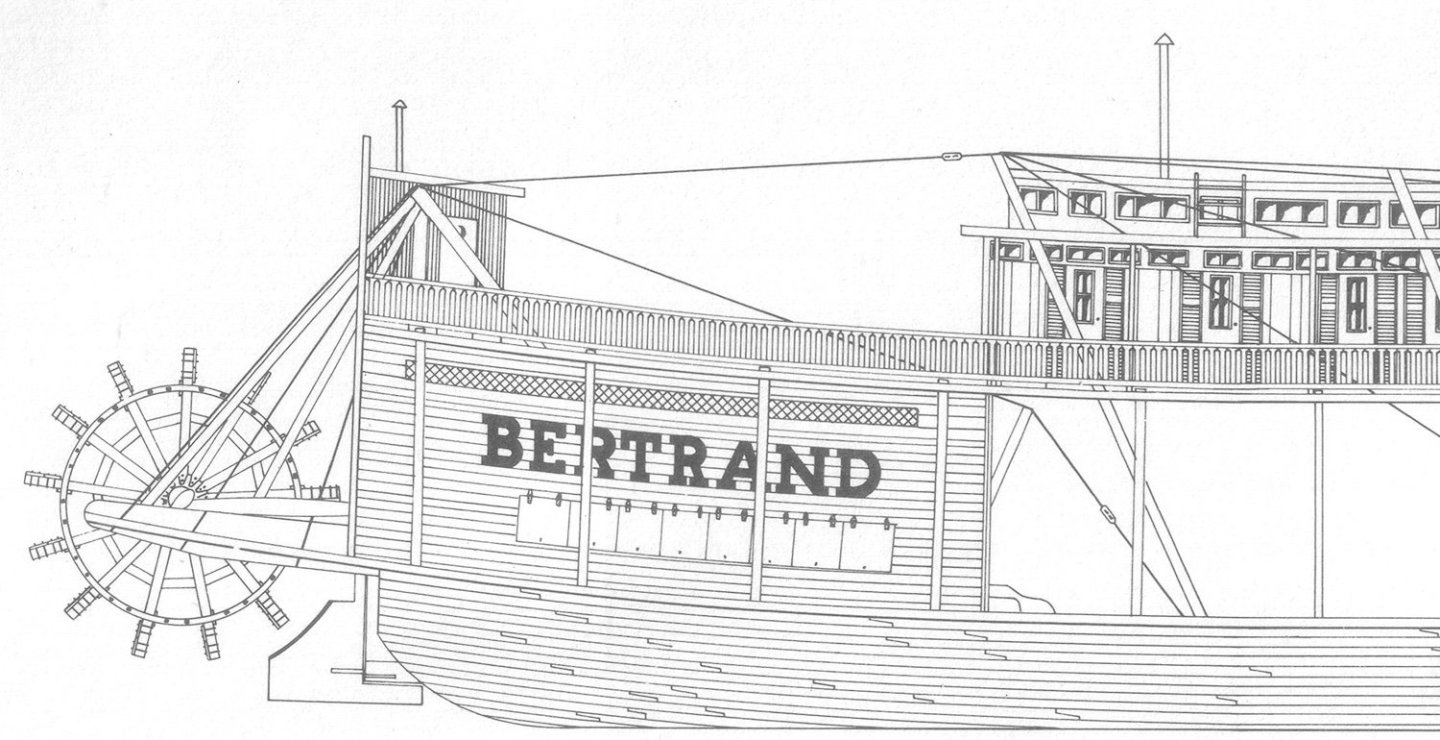
I completely agree about the potential value of building smaller craft in larger scales. Another thought occurred to me while reading the responses here: maybe consider altering the purpose of your modeling and trying models that are simpler and more artistic, more representative than to-scale? For example, I could imagine a really neat-looking modern towboat and barge set built from basic lumber that would simplify details but capture the essence of the vessels, especially if the finish and presentation are well thought out. Or maybe a cargo ship with relatively simple lines? Think of it as 3D art rather than literal scale modeling. And something like that could still have value beyond your own collection; if it's a design relevant to your region, then a local library, small museum, or historical society might still value a model that would engage the average visitor. Even a simplistic model helps people understand the three-dimensional nature of a vessel, better than a photo or drawing. For example, here's a pretty simple model of the Missouri River steamboat Bertrand, proudly on display at the museum displaying her artifacts just north of Omaha, Nebraska (all photos mine). Something like this would be more manageable than a truly scale model, but still has a very real role to play in engaging visitors. Note that the museum prominently displays this alongside a much larger, more detailed, very much to scale model: Both have a proud place in the museum's collection. If nothing else, the simpler one is probably more understandable and accessible to kids than the giant hyper-detailed one. I wonder if you'd consider something similar that would work for your current abilities yet be of real value to a local entity? EDIT: Shortly after posting this, I ran across a perfect example of what I'm talking about: the current Australian Couta boat build by @Louie da fly. As the builder (Steven) wrote, "It was never intended to be a 100% accurate model, more just something simple that could be made easily to raise funds..." but it so far it seems to me to do a great job of capturing the essence of a specific design of regional historical importance while being a relatively straightforward design and project, compared to a truly scale model.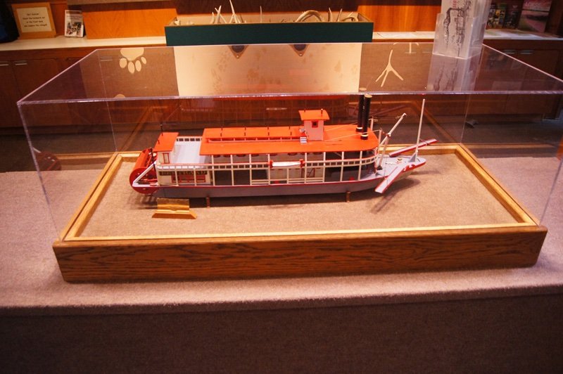
-
Would you buy pre-owned wooden kits?
Cathead replied to Frank Burroughs's topic in Wood ship model kits
I second Bob's advice. Older kits are very likely to have subpar quality materials, especially things like cannons, fittings, and rope, even if the wood is fine. Any money you save may well be sucked up by upgrading these items. And it's much more likely the instructions are poor, or at the very least make a lot of assumptions about your knowledge and skill set. Experienced modelers can enjoy the challenge of such kits, but there's a good chance they'll be a trap for a newer builder. Start with a new kit from a really reputable modeler, something small enough to not feel like a giant outlay if that's a concern, and use that to develop enough skills and comfort that you can then dive into "restoring" older kits. -
This is a spectacular model and a real joy and inspiration to follow. Thank you so much for sharing your detailed progress with us! I will miss this log...
- 208 replies
-
- 3
-
-
- kitbashing
- Woodcarving
- (and 4 more)
-
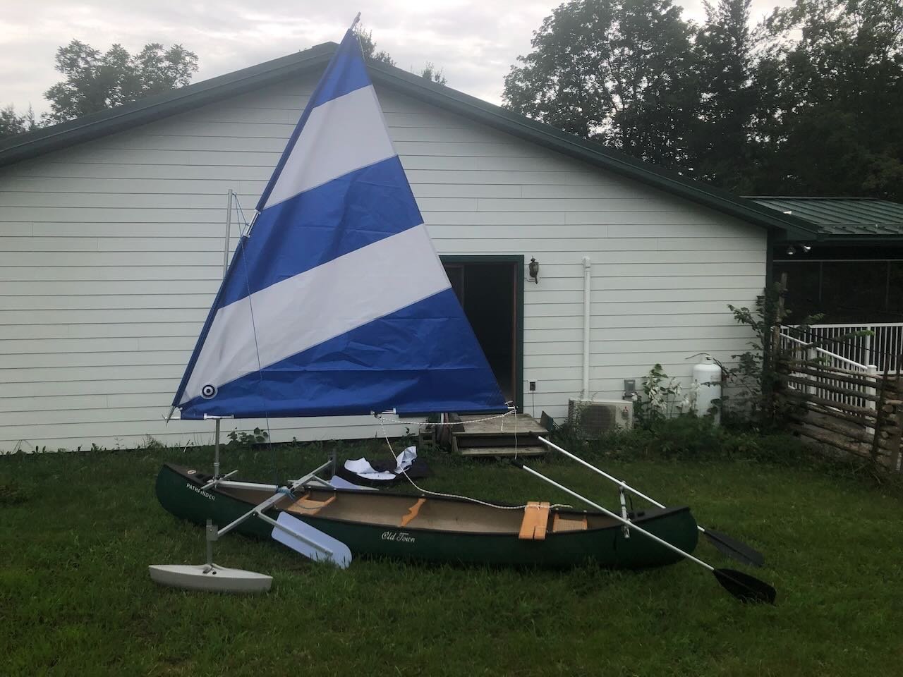
Forgive me for a slight diversion, but this discussion of side rudders and the note about one on each side really fascinated me, as I recently purchased a kit that converts a regular canoe into a sailing vessel. As it's difficult to mount and operate a centered rudder on a canoe, this setup uses dual steering oars mounted on a cross-beam. The idea in this case is to use one at a time (whichever is on the lee side) and let the other trail in the water. These also swivel horizontally and vertically so you can store the unused one up on the stern. The system works amazingly well, but I had no idea the dual-steering-oar setup had such a pedigree, I figured it was a modern hack to make the canoe-sailing thing work! To illustrate the point, here's the setup in my backyard and in action on a local lake. Having learned to sail on normal sailboats while growing up along a US Great Lake, the whole side-oar thing was new to me in practice (though I was familiar with its use in Viking vessels); it does indeed work very well. I don't want to derail this thread into a long discussion of canoe sailing, I was just fascinated by the convergence of ancient and modern.

-
I've used simple artists' pastels to weather models for a very long time, including my past steamboat models logged here, as well as various model railroad applications. If it were me, I'd take each hatch plank and rub a bit of suitable pastel or weathering powder onto it. The inevitable slight different in application thickness and style will likely give you the subtle effect you're looking for.
-
I just have to say, as a spectator and not a builder, I would love dearly to see video of a largemouth bass striking a model tug. Move over, JAWS. Too bad you can't mount harpooning gear on her!
- 72 replies
-
- 2
-
-
- Seguin
- BlueJacket Shipcrafters
- (and 2 more)
-
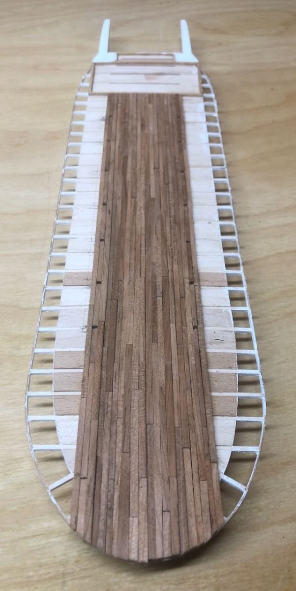
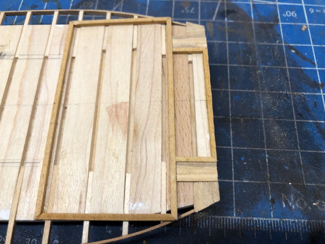
I've made it about halfway through the decking. Just a slow process of cutting and laying planks one row at a time, trying to keep them parallel with the centerline. It's definitely more challenging with home-cut planks as every strip has slightly variable dimensions, so laying out each run is time-consuming. I'm definitely still an amateur at cutting out consistent scale lumber. Therefore this has been a lot more like planking a hull, in which each deck plank is a mini-project, than planking a deck with nice consistent commercial strips. So I end up laying a couple strips every evening, or whenever I can steal a bit of time. But here's what it looks like so far: The photo makes it look better than it is; the work is actually pretty rough. The planks are thicker than I initially intended, and the surface is pretty variable. I intend to sand the deck down smooth once the planking is done. There are also some disturbing gaps between some plank edges that I expect to need some sawdust filler on. The good news is that (a) unlike a sailing vessel, most of this deck will be relatively hidden, and (b), it's supposed to look rough-built. You can see the two parallel lines of holes left in the decking, where the boiler deck support posts would go. If you recall the framing I built in the last update, I used that to lay out exactly where the posts should lie and carefully arranged the deck planking runs so that the post holes would fall within a single run of planks. I started at the center and worked my way out, to help ensure that everything stayed parallel to the hull. This has worked well, but its downside is that the "best" planking got laid down the center where it'll be mostly hidden while the most visible planking (along the outer guards) will be done with whatever dregs I haven't used yet. I may end up cutting some more planking to avoid this potential problem, as I can tell I'm slowly concentrating the most problematic pieces in the so-far-unused pile. But it's progress, and I think will turn out well enough in the end. Thanks for sticking with the slow progress on this part.

- 393 replies
-
- 20
-
-
Timber-framed outdoor kitchen - Cathead - 1:1 scale
Cathead replied to Cathead's topic in Non-ship/categorised builds
Gregory, the scent fades quickly when the wood is in open air, so there's none around the kitchen. Indoors, especially in confined spaces, it remains strong much longer. For example, I built a simple cedar chest several years ago for storing woolen sweaters, and that retains an intense aroma when you open the lid. Thanks for the likes & comments! Some of you may be now planning a road trip to central Missouri... -
Timber-framed outdoor kitchen - Cathead - 1:1 scale
Cathead replied to Cathead's topic in Non-ship/categorised builds
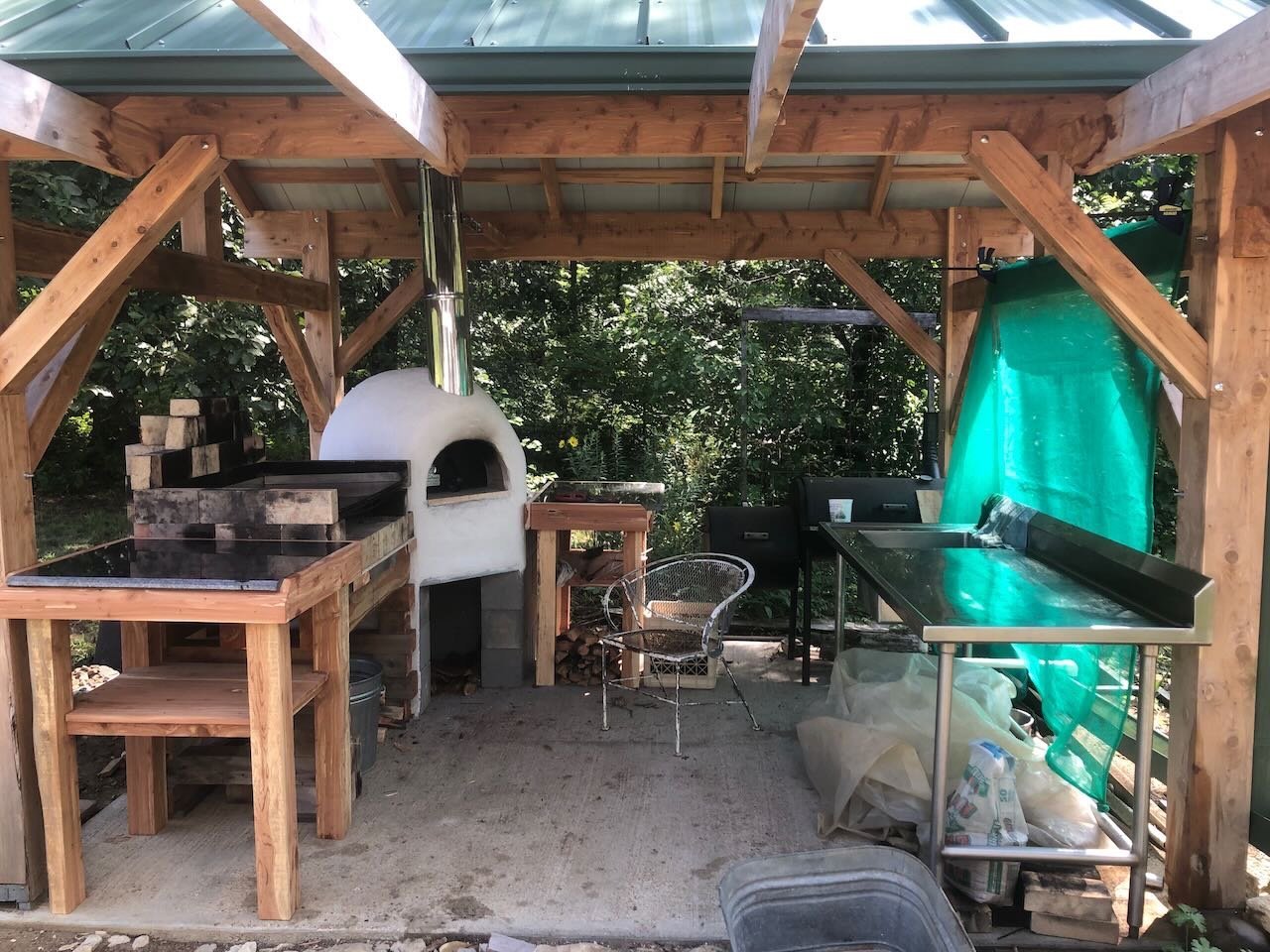
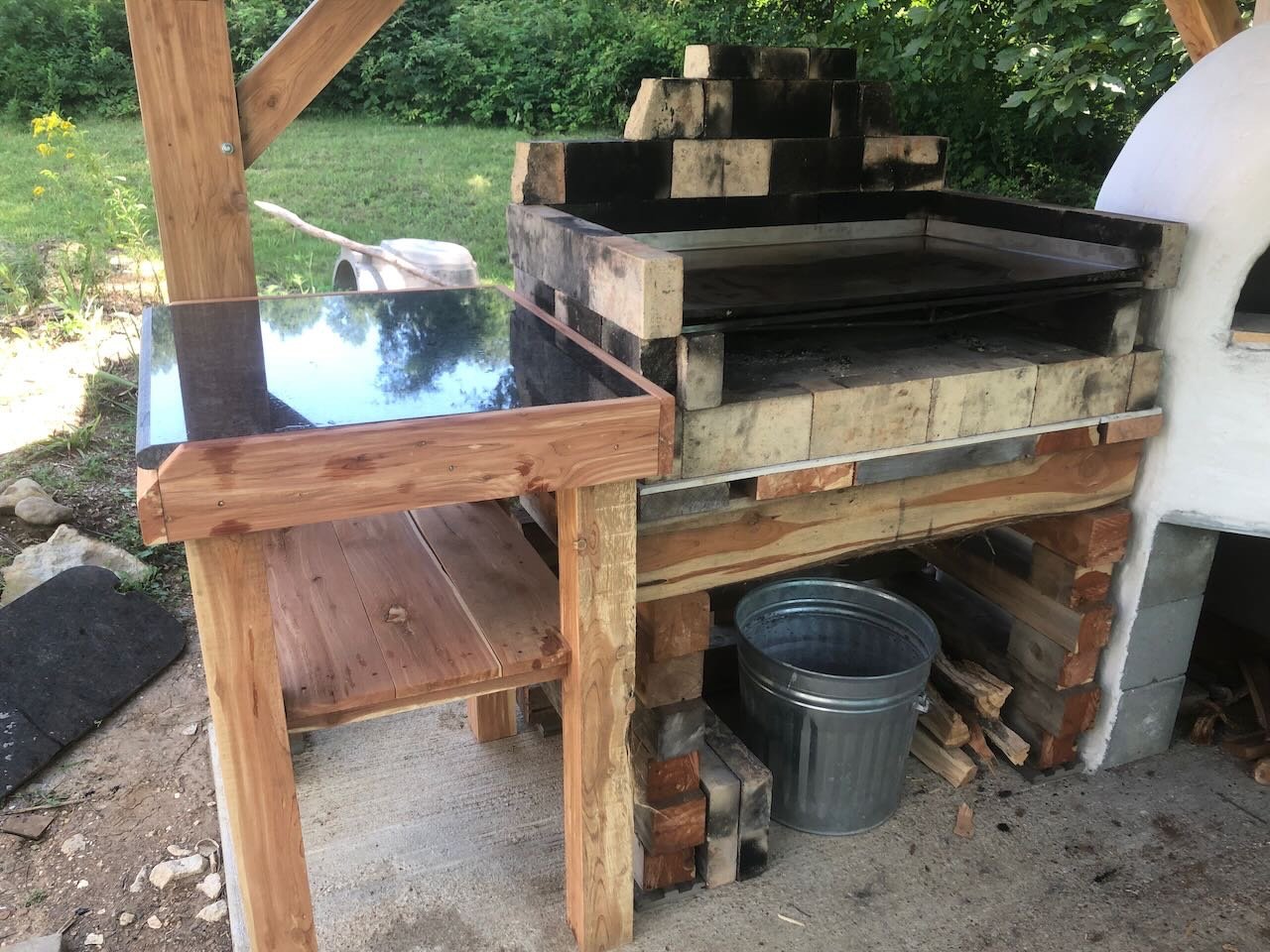
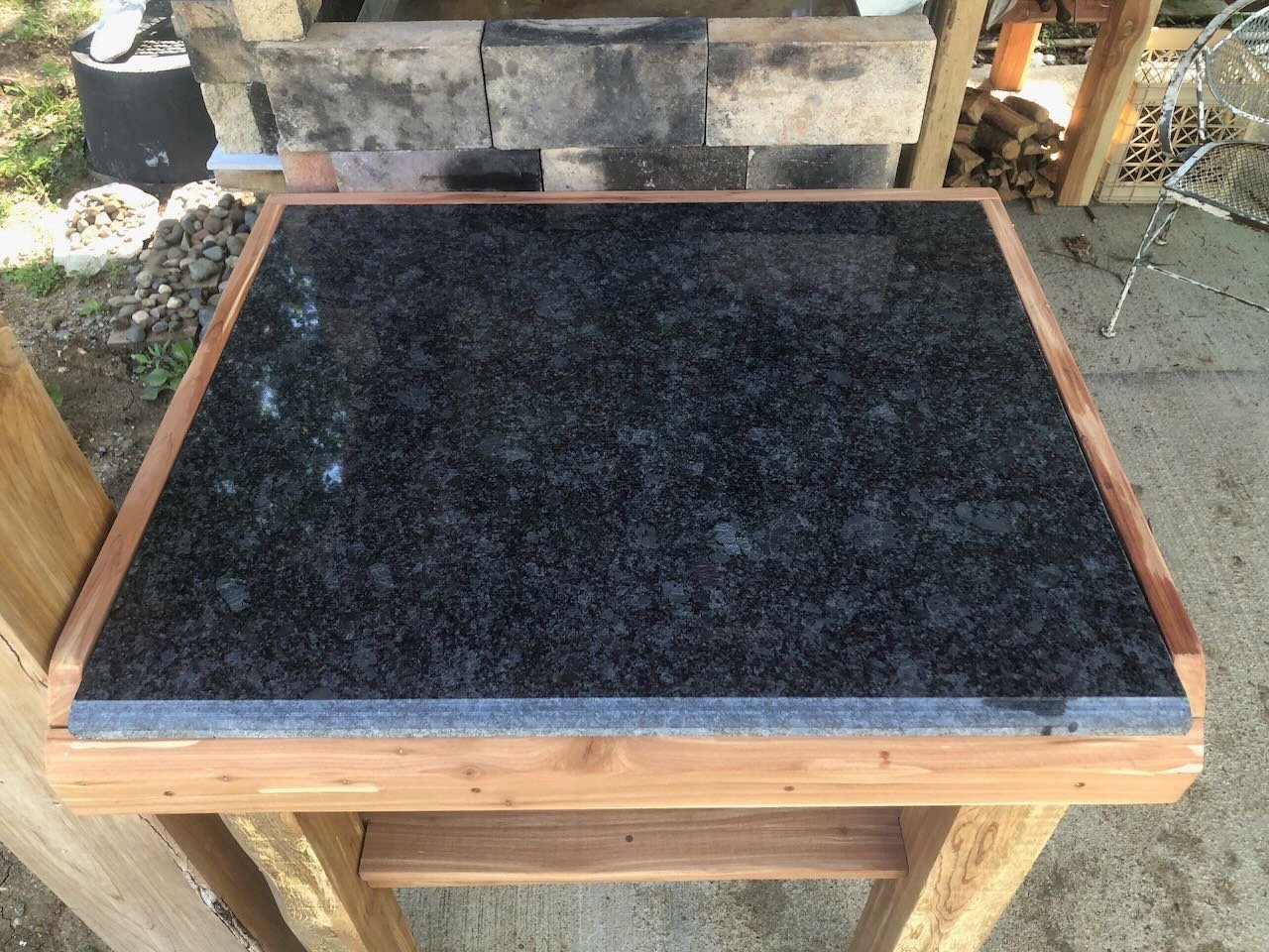
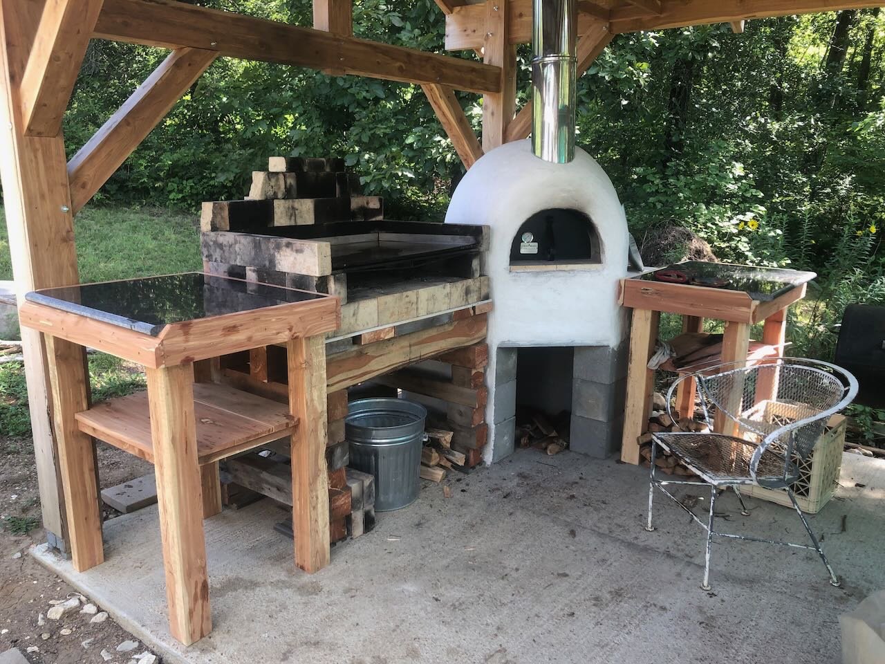
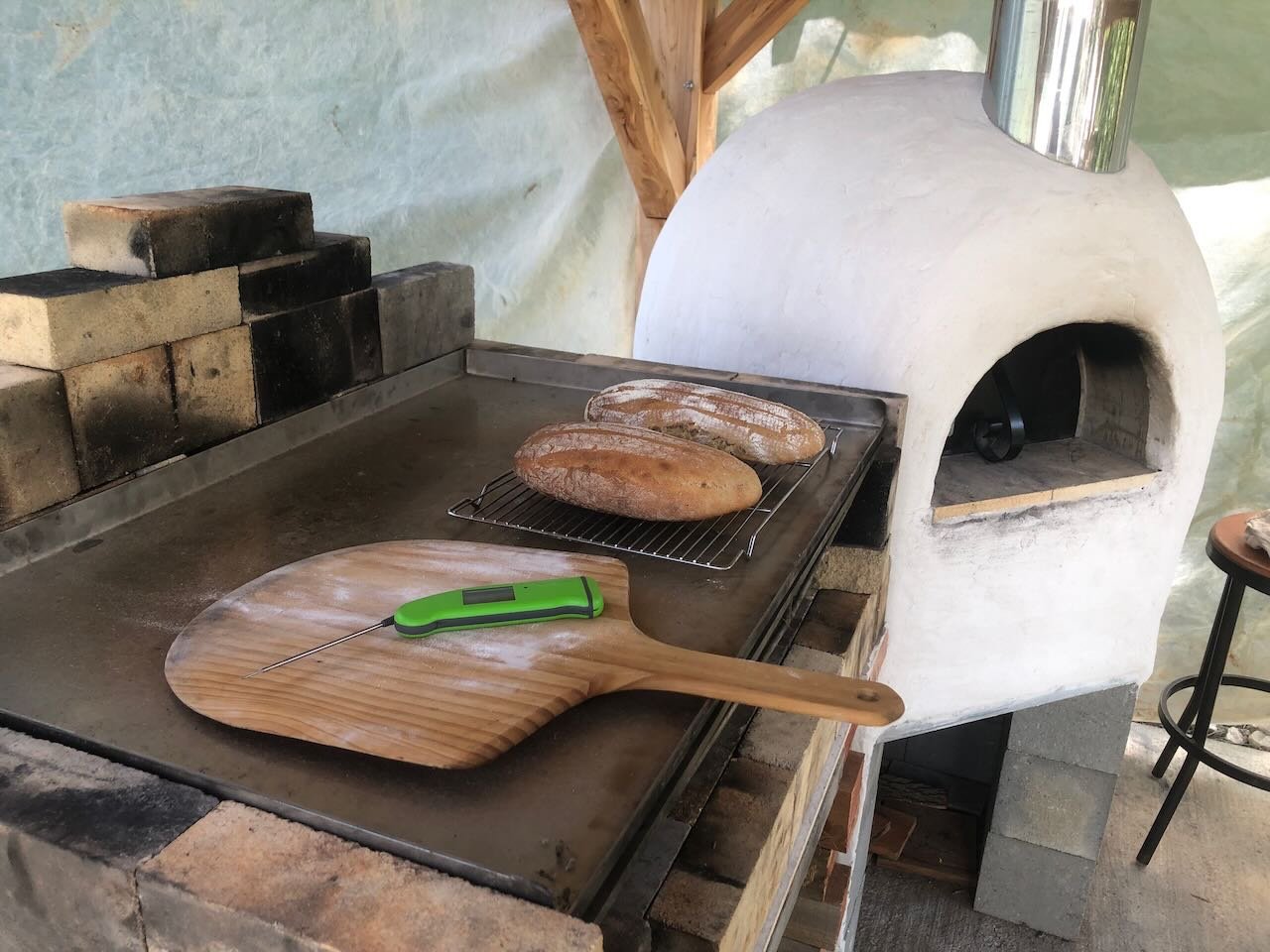
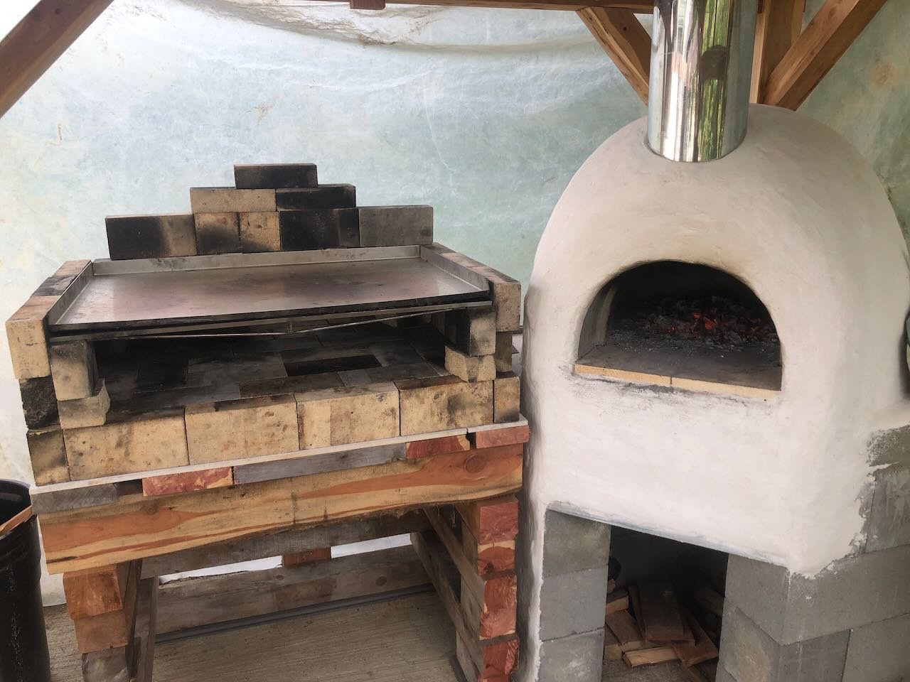
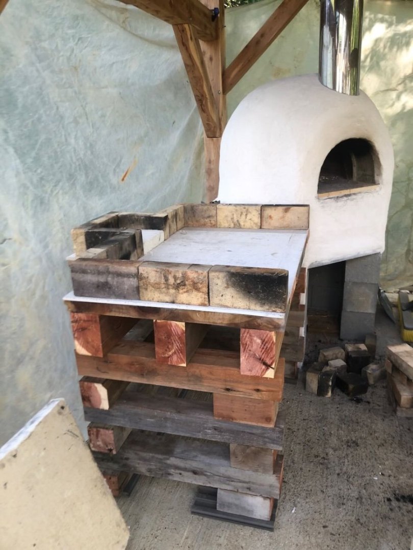
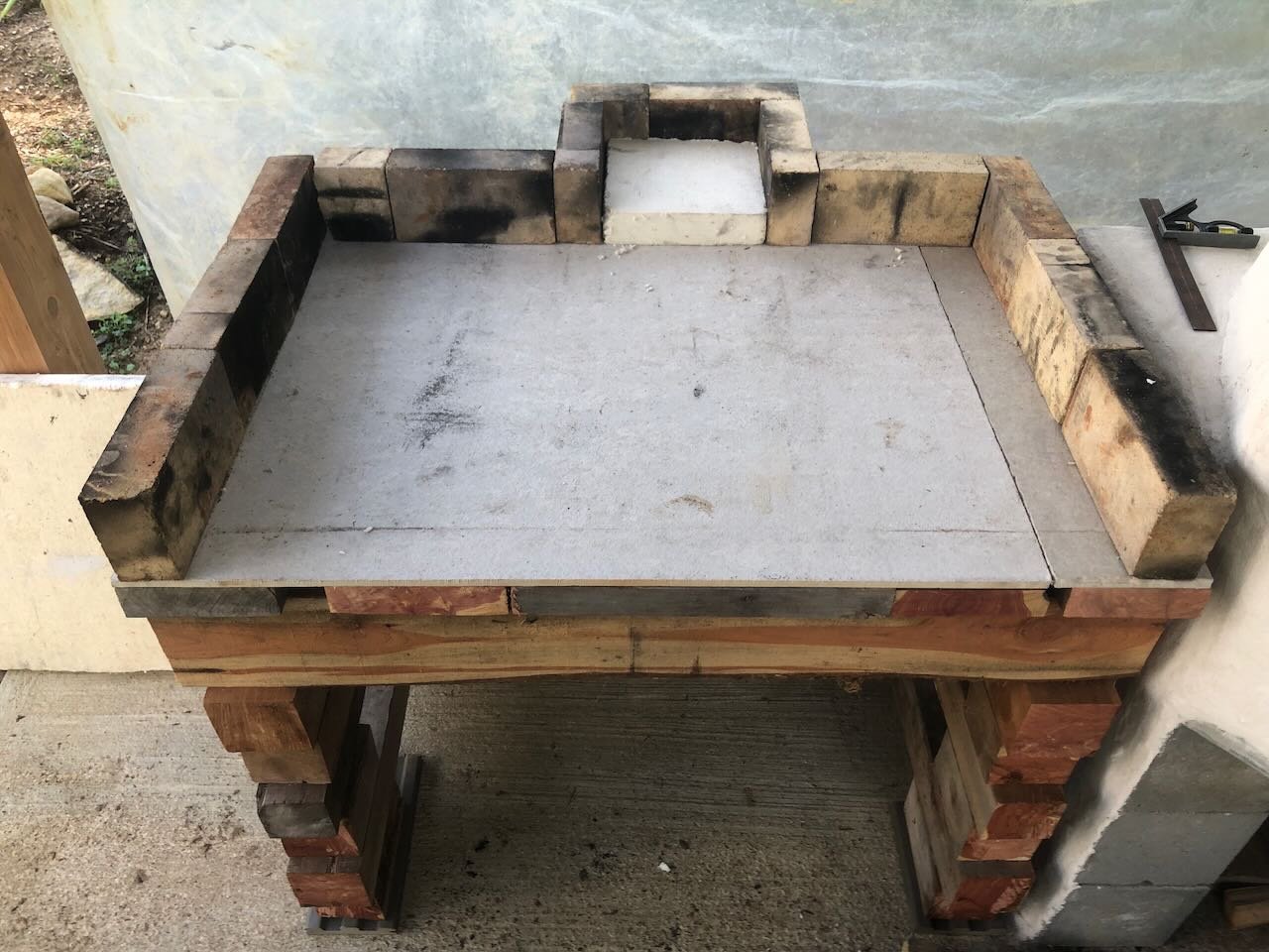
Here's another upgrade to the outdoor kitchen. This time I built two stone-topped work stations that provide more counter and storage space around the grill and oven. These are built from yet more on-farm cedar lumber, just stuff I had lying around from previous projects. The stone tops were free; we got them from a counter-top place in our region that has a giant discard pile of waste stone left over from their own cutting projects. They have pallet upon pallet of this stuff sitting outside, that they have to pay to dispose of, but they're thrilled for anyone to come and take whatever they want for free. We have lots of slabs from them that we use around the house for various purposes, and selected this pair for their nice finish and appropriate size. They have minor flaws (aren't cut/trimmed quite square, rounded edges aren't polished) but we don't care about that. They make great work surfaces, easily cleanable, and are appropriate additions for a couple of geologists. The slabs simply rest in a three-side wooden enclosure; the whole structure is heavy enough that they aren't going anywhere. Here are a few more views. These make it so much easier to work in the kitchen, since there's now plenty of space to place ingredients, pans, etc. as well as storage for implements like fire pokers and ash pans below (out of the way of food). With these, the essential infrastructure of the planned kitchen is complete! It's actually fun to go back and compare to the original 3D digital model I developed as a loose guide to the planned concept: The oven and sink are where we initially planned them, while we've swapped the location of the smoker and grill; the latter is also larger than drawn above and the extra work table has been broken into two smaller ones. But the basic idea is the same, even down to the trellis along the west side. So much good food has been coming out of this on a weekly basis, it's still a bit stunning to us. The project isn't complete, there are various aesthetic upgrades planned. For example, we still intend to cover the oven dome and foundation with local river rock mortared in place, though that probably won't happen until next spring as it will take us time to collect and we won't have time to do the overall work before the weather gets too cold for curing mortar. I also intend to mount two clean buck skulls with antlers in the opposing gables; that I'll hopefully get to in the next month. And we'll keep coming up with small tweaks as we use the facility more. But functionally, it's complete! After almost a year of direct work, and much more than that of dreaming, planning, logging, milling, and so on, we finally have a functional outdoor kitchen that's exceeding our dreams so far. Yesterday (Saturday) we fired it in the morning and hosted two pizza parties for friends (noon and evening), and in between roasted another batch of venison, lots of tomatoes and onions, pans of okra and bitter melon, a tray of sweet potatoes, a dozen or so pitas, and so on. Once again we can eat for much of the week on what we cooked this weekend, in addition to things that went directly to the freezer for winter (like roasted tomatoes). I think you get the idea at this point. I'm not going to food-blog everything we do, but I'll keep updating this log occasionally as something new and interesting happens, either on the detailing or something new food-wise, like some especially fun food or using the grill to boil down maple sap in the spring. Thanks for tagging along on this rather unusual 1:1 scale project. It's been fun to build and share, and I appreciate all the interest, questions, and support along the way.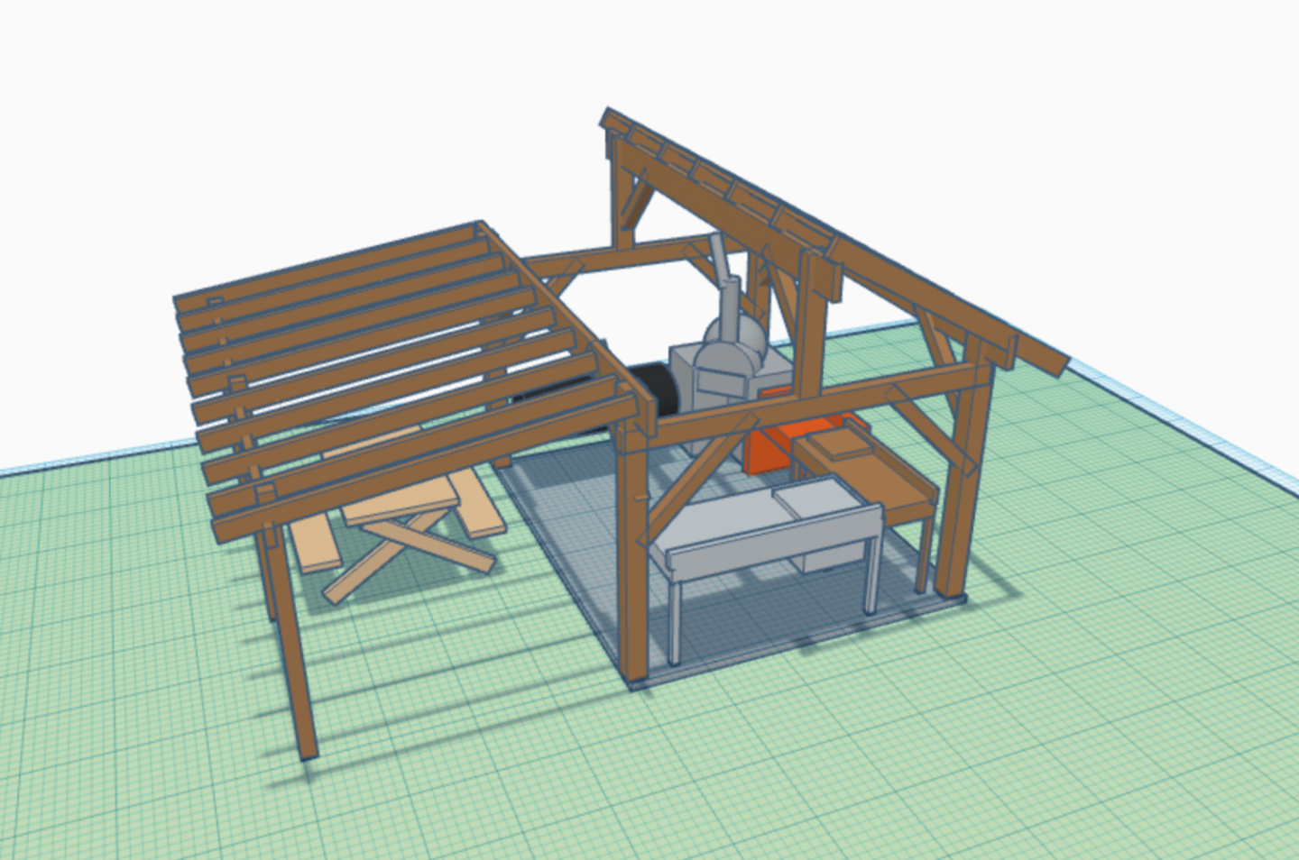
- 131 replies
-
- 13
-

-
-
You get what you pay for. Pinching pennies on a starter kit is just as likely to frustrate you as cheap kits are more likely to have poor materials and instructions. Investing in a kit from a quality company is a more reliable path to enjoyment and proper learning.
-
Looks like a very distinct project; I'll be interested to follow along. I strongly considered joining the Coast Guard as a youngster but life took me a different direction.
- 46 replies
-
- 4
-
-
- Fast Response Cutter
- Dumas
- (and 2 more)
-
On a "typical" sternwheelers, to the extent there was such a thing, the heads were hung off the very aft of the hull, where the waste was disposed of by the paddlewheel. This allowed easy passenger access from the boiler deck, the main passenger area. For example, see this drawing of Bertrand, where the heads are on the boiler deck overhanging the stern above the engine room. But as I mentioned earlier, no photos of Peerless show such facilities. For example: I don't know where her heads were, but a small stairway in the middle of the hull forward of the engine room doesn't preclude any number of other possibilities. The lack of "normal" heads is probably another line of evidence that she wasn't designed for carrying passengers. It's actually possible there's a small head on the main deck, hidden within the engineroom at the very back of the hull, which we can't see from external photos. That would be a logical location for a crew-only freight vessel, preserving the geometry of easy disposal without needing to build a separate structure up on the boiler deck. But again, that doesn't affect the location of the stairway further forward.
- 393 replies
-
- 12
-
-
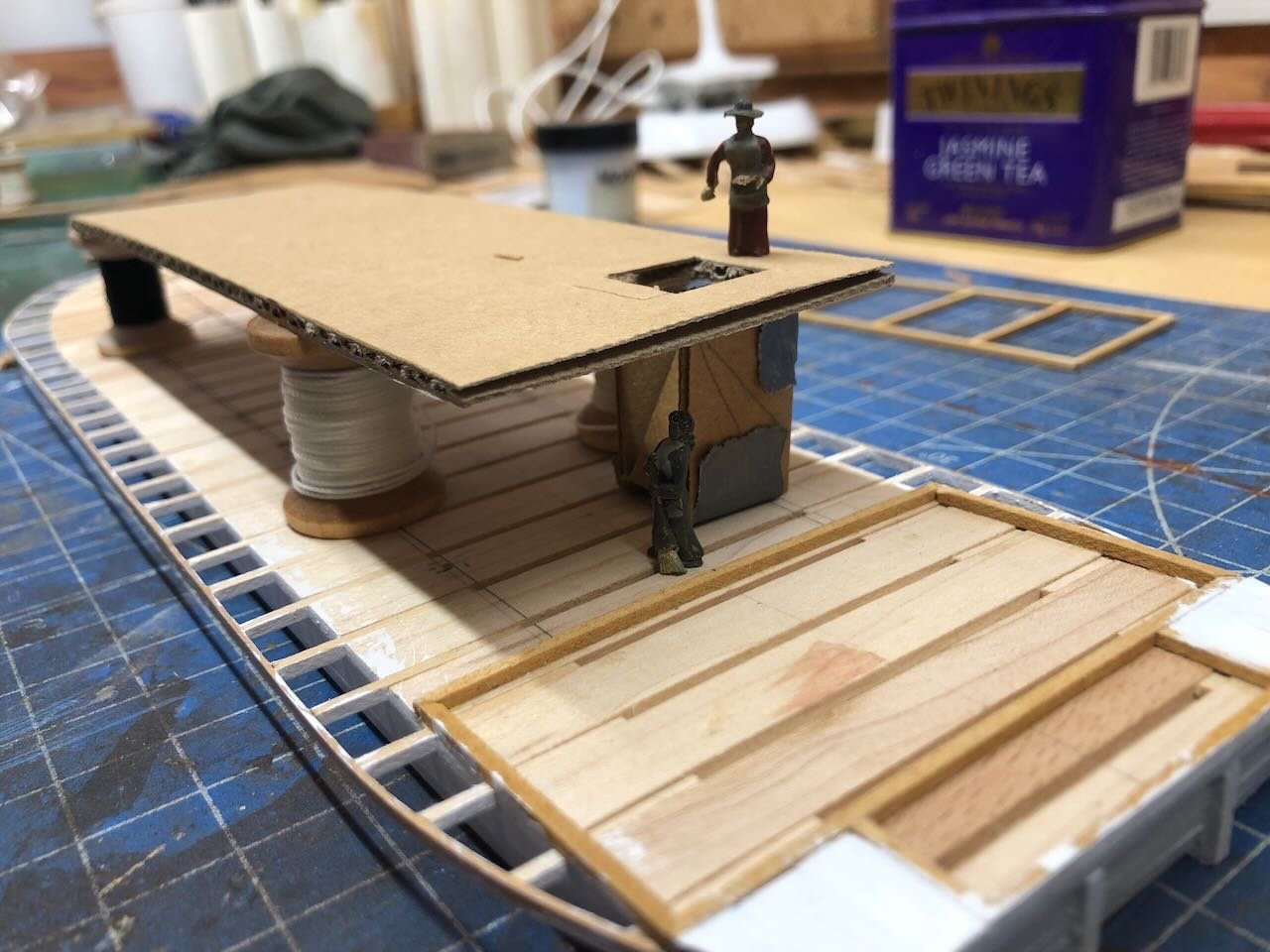
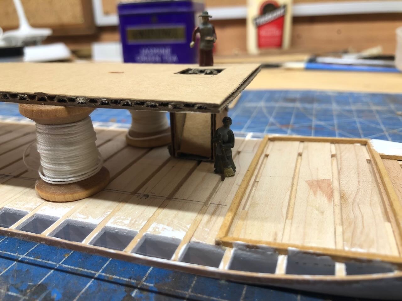
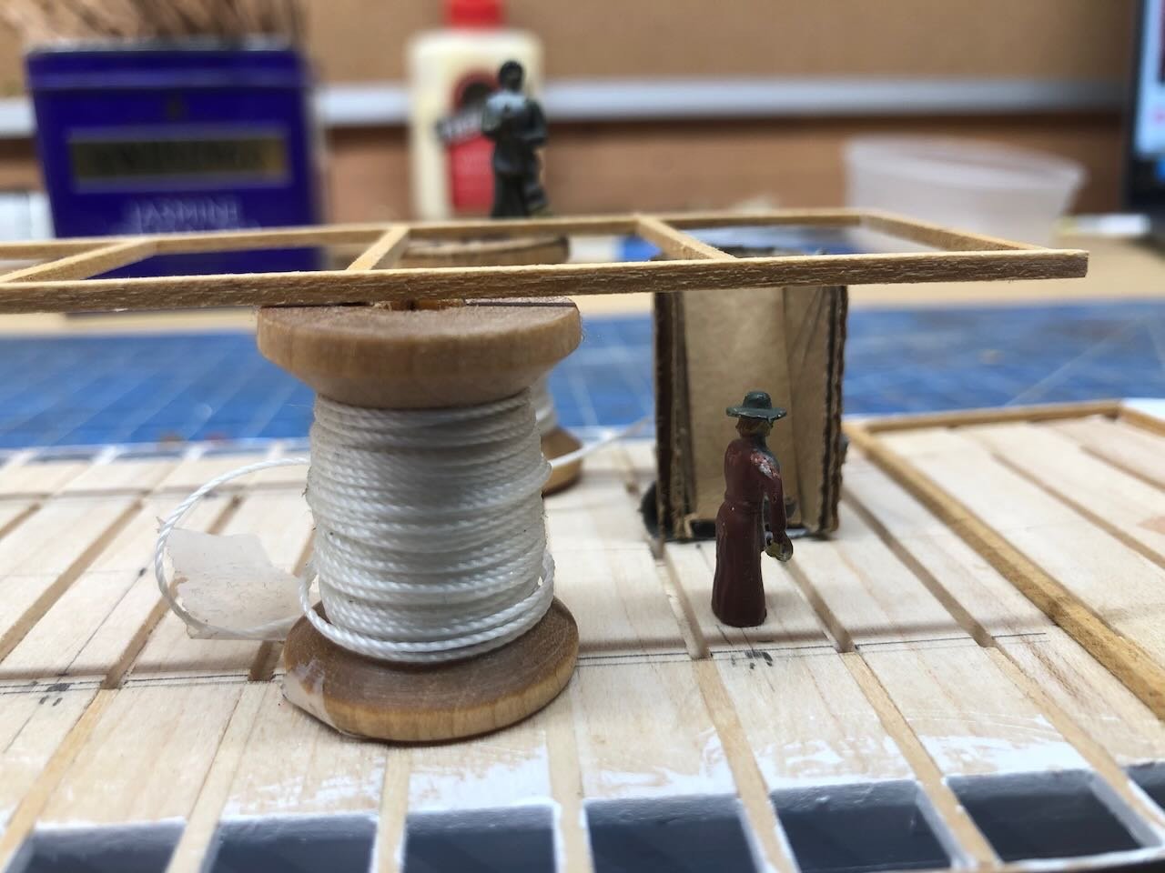
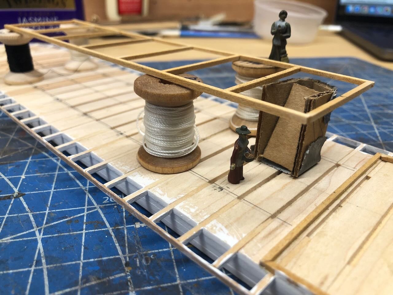
Strong language is as renewable a resource as wood here! No chance of running out. I did a quick experiment to test out the aft stairway concept. I built a small cardboard mockup of an enclosed stairwell, using a 60º angle that's fairly steep but well within nautical tolerance for something intended for crew but not regular passenger use. In the two photos below, the boiler deck framing is propped up on some bobbins that happen to be right about a scale 8' tall, near-perfect. In the next two photos, I replaced the frame with a piece of cardboard with a "hatch" for the stairwell cut out, to better represent the solid deck. Recall that the framing on the main deck, aft of this, is where the solid engine room superstructure will be. This seems to work. The stairwell accesses the main deck right at the centerline, a bit forward of the enclosed engine room, and accesses the boiler deck just aft of where the upper superstructure ends, as hinted at in the photo discussed above. This would be a sensible place for a crew stairway. I think this would work, both on the model and in real life. Anyone see a reason otherwise?
- 393 replies
-
- 12
-
-
That's definitely true of me, the design is constantly playing in my head. I find, over and over, that I bog down if I try to draw complete plans and schedules. I seem to enjoy the fluidity of building as I go, even if it gets me into corners at times. I also seem to like the problem-solving when I actually have the wood/model in my hands, as opposed to when it's just on paper or pixel.
-
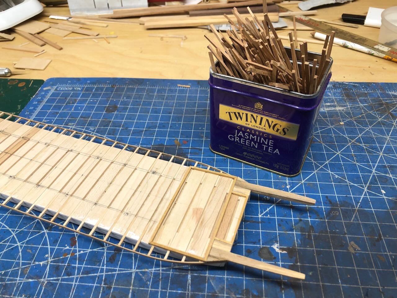
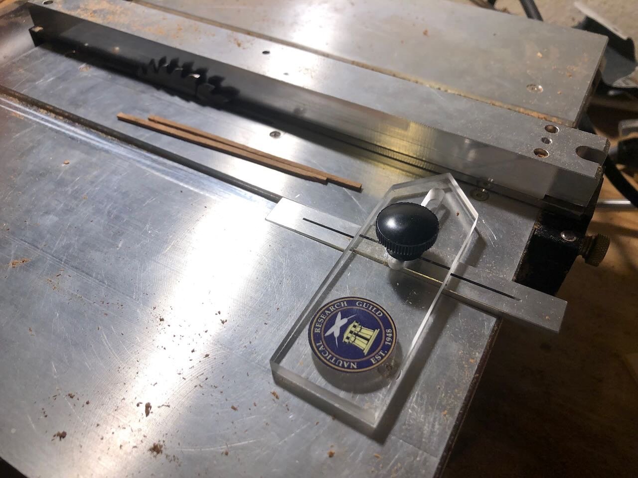
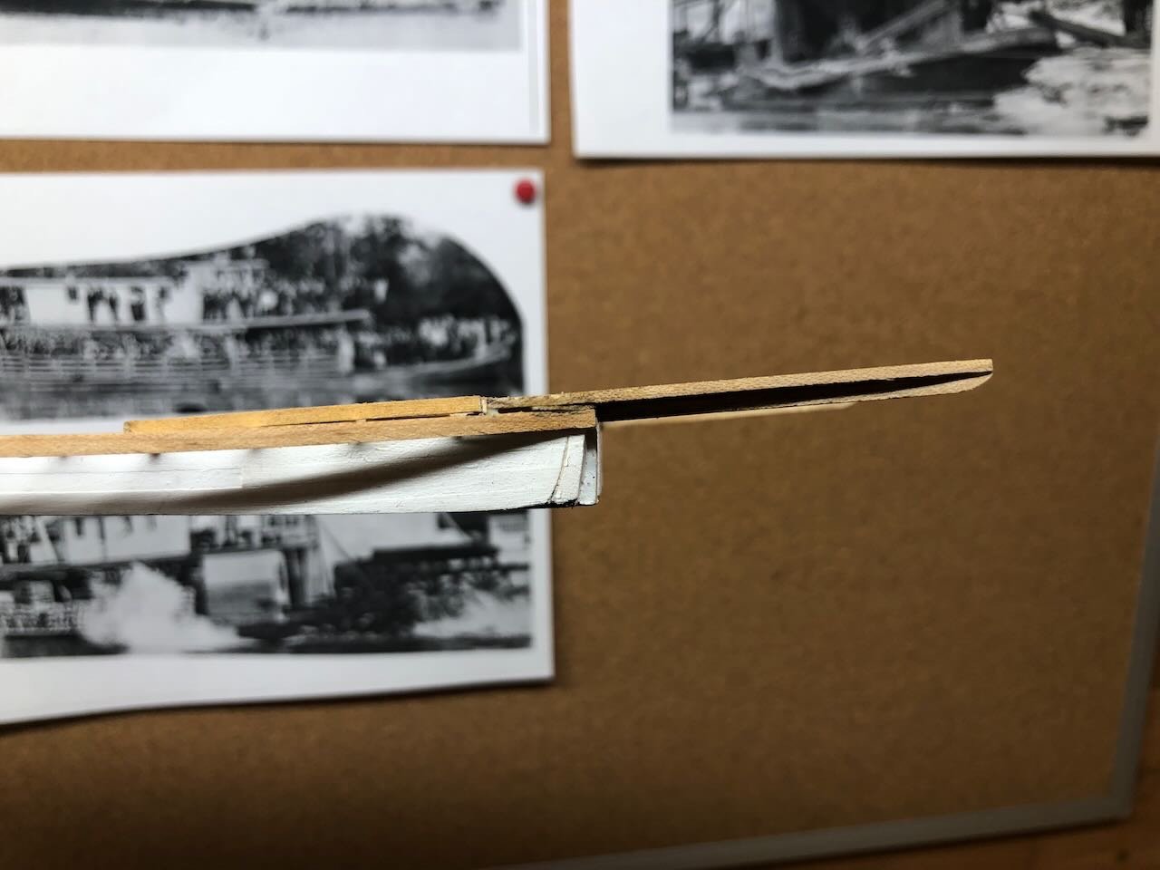
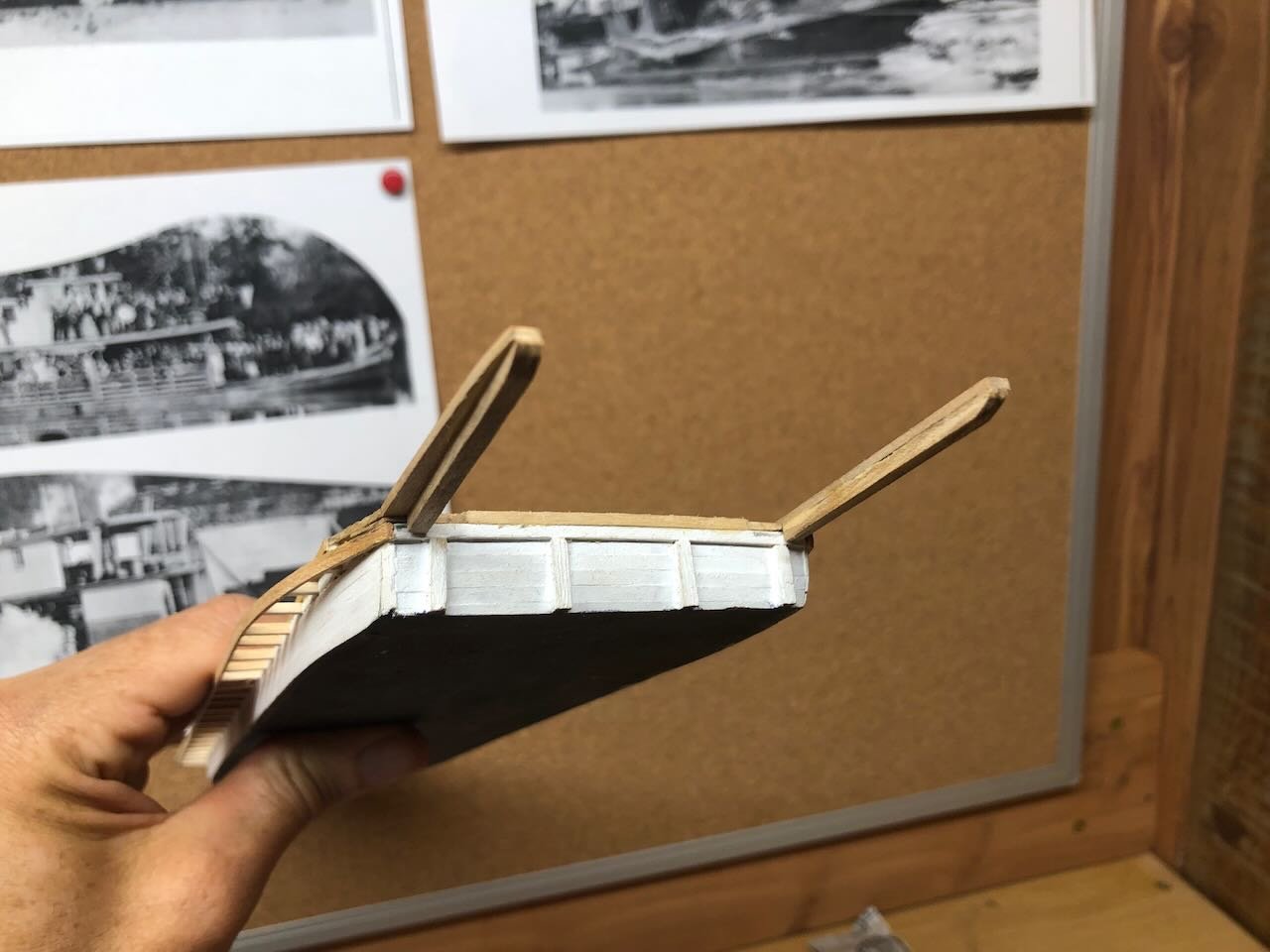
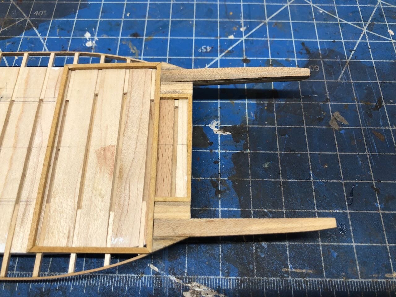
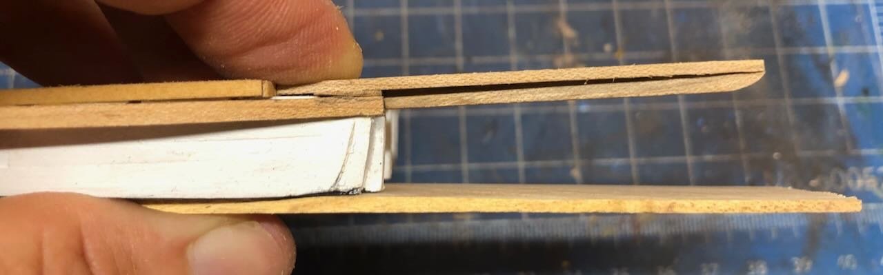
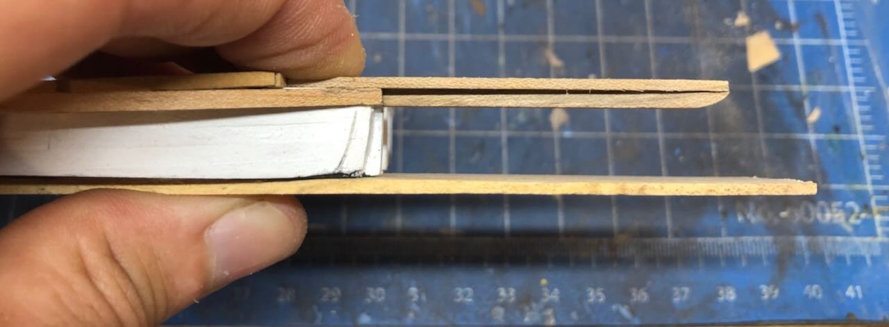
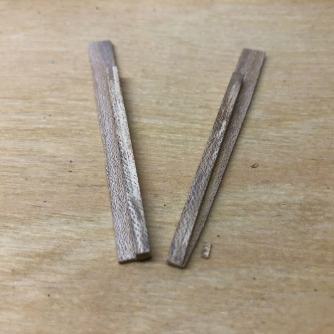
Well, I was all set to get to work on planking when I realized there was another task to complete first. I'd completely forgotten about the extensions that support the paddle wheel. This is the problem with scratchbuilding; I can't rely on anyone else to have thought through a logical construction process! Since I don't have any really clear views of this area, just one blurry stern shot, I used modeler's license and came up with an approach that suited me. First, I made two L-shaped beams from scrap maple and carved/sanded them to a curved shape. Below left, a rough beam; below right, a finished one: When I test-fit these on the hull, I discovered that their natural angle of rest didn't angle upward as much as I wanted; these should continue the natural rise of the stern but due to local irregularities in the hull, they laid almost flat. Like this: So after composing some strong words for the designer of this kit, I set about fixing the problem by cutting and shaping very thin maple wedges that would elevate these beams juuuuust a little. Here's the result; much better: Here are the wedges in place, from above: And here are the wheel support beams in place, with suitable filler on either side: With those in place, I really do think I can turn to deck planking. So I spent the rest of the evening cutting a large and chaotic pile of planks from scrap cherry, using my Byrnes saw and NRG thickness gauge (thanks, Kurt!). Here's the hull with a tin of planking. This stuff isn't entirely consistent in thickness or width, and it's going to be an adventure laying out a nice deck. I cut it a bit thick, assuming that I'd want to sand it down even, so that's not too much of a worry. And as has already been said, these backwoods boats are allowed to be a little chaotic in their construction. So we'll see how this goes. Thanks for reading, and for any likes and comments you're generous enough to share.
-
Timber-framed outdoor kitchen - Cathead - 1:1 scale
Cathead replied to Cathead's topic in Non-ship/categorised builds
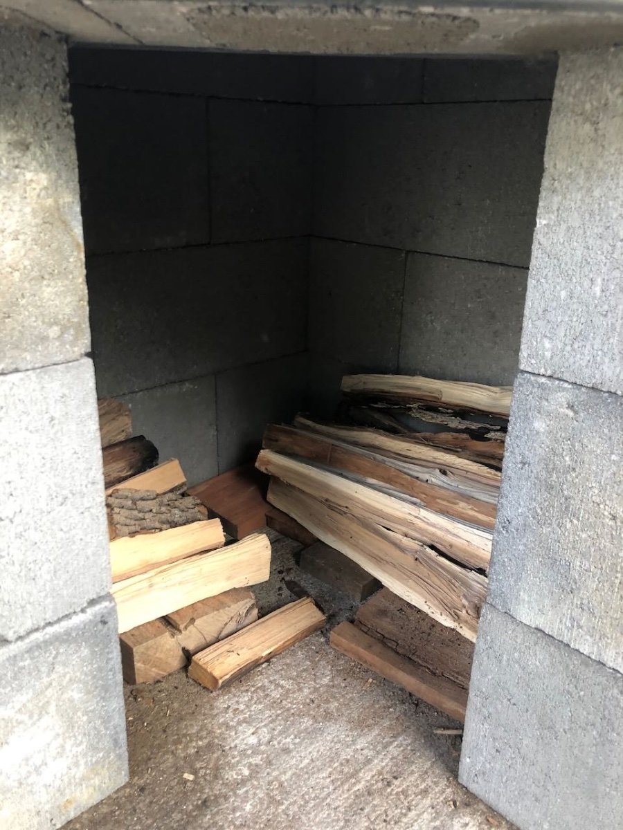
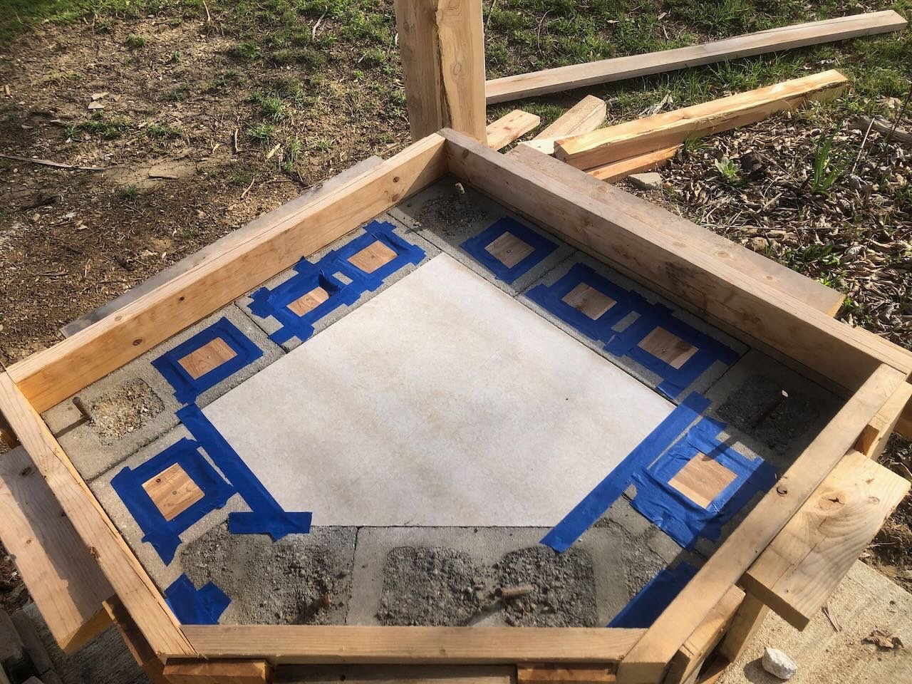
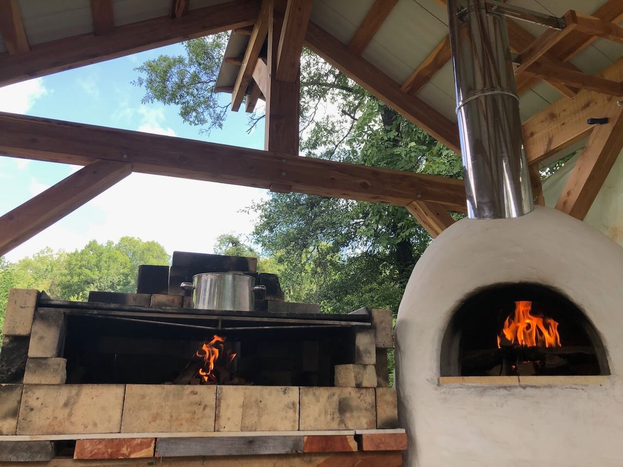
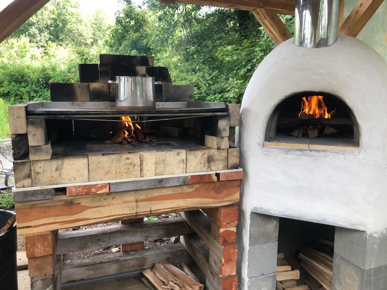
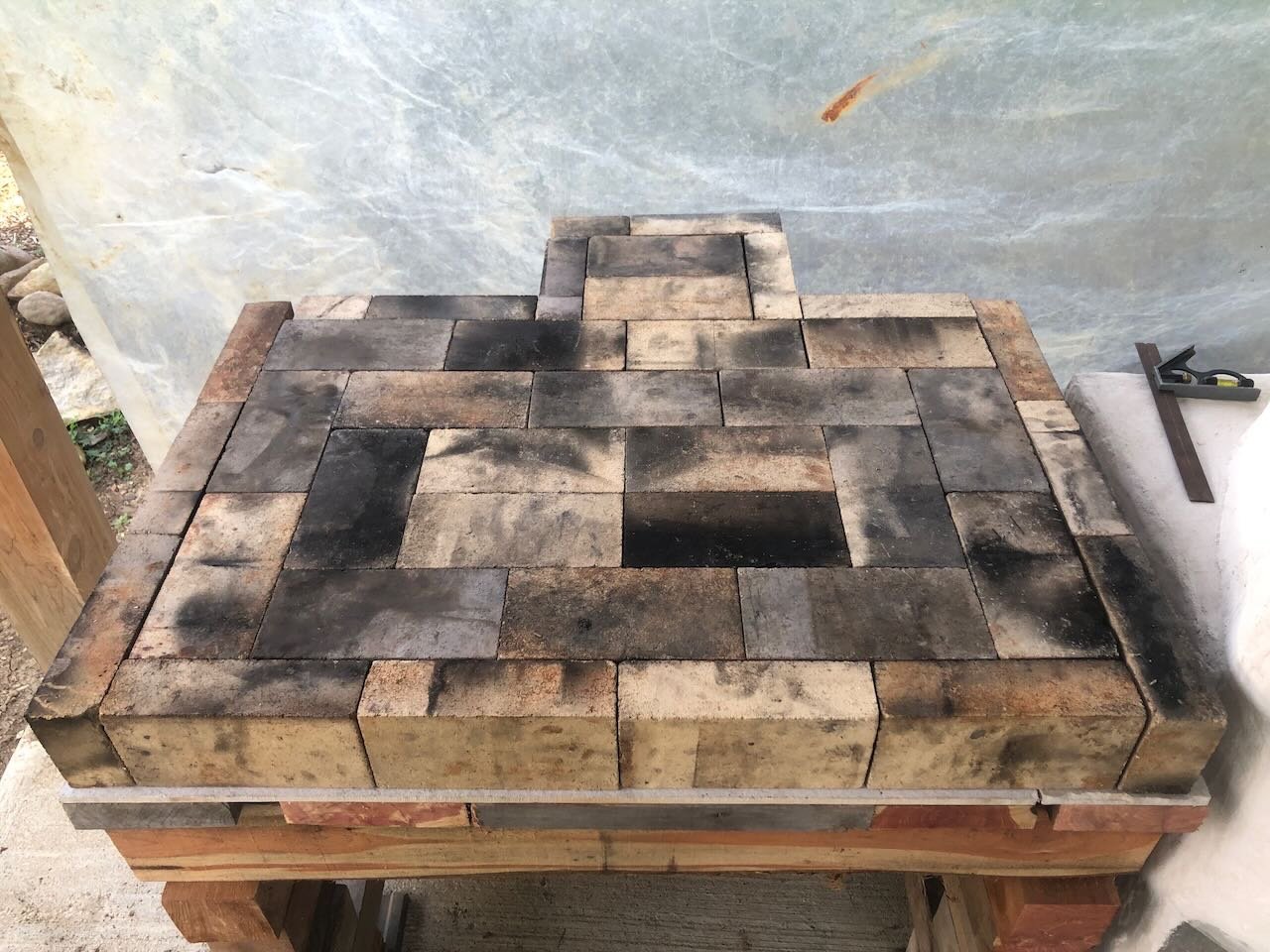
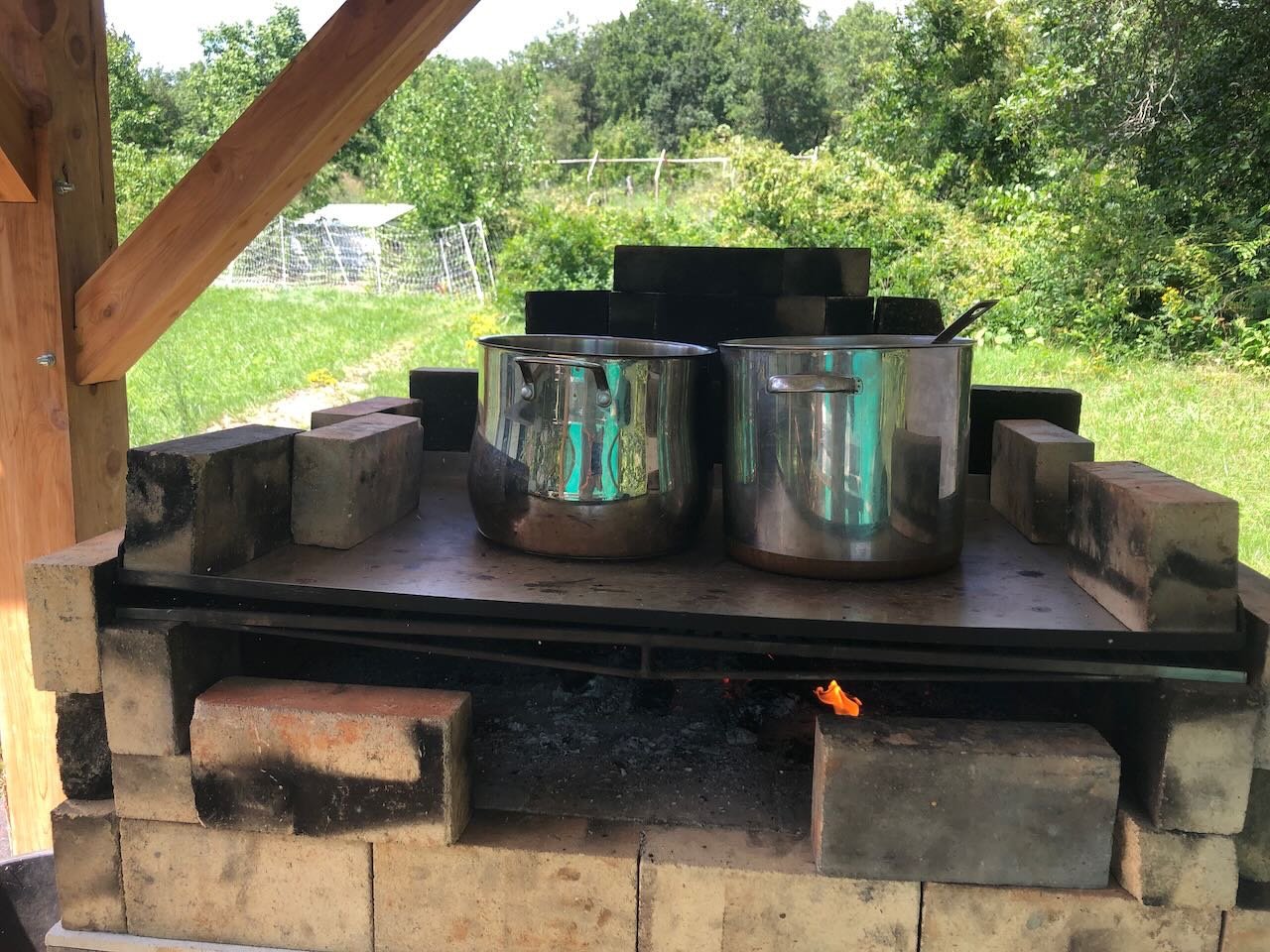
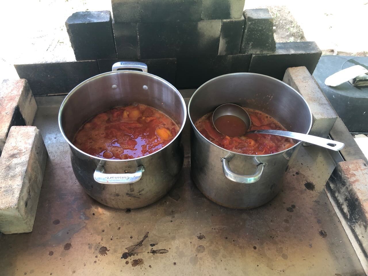
Another weekend, another step forward. Earlier in the week, I built a first draft of the firebrick grill planned as a companion to the oven, intended both for standard grilling applications and bulk cooking (e.g., reducing maple sap to syrup or boiling down tomatoes for canning). The plastic sheeting in the background was set up for a forecast of severe storms, to keep some windblown rain out while we were working on this. It will not be present when the grill is hot! I first built cribbing of 4"x4" cedar posts. Like other wood in this project, this was cut & milled on-farm, but these were mostly "recycled" in the sense that they were salvaged from other projects or were leftover waste (for example, cutoffs from longer posts). The top beams were 4"x6" to help support the weight of bricks across the open span. On top of these I laid a layer of cement backer board, using leftovers from the same material used to support the concrete slab on which the oven is built. As a reminder, here's the oven foundation with its open center, and the backer board in place: And here is the grill cribbing with its layer of leftover backer board and a first layer of bricks around the edge: On top of this, within the firebrick rim, I laid a sheet of 2" ceramic insulation board, again using material left over from building the oven. As a reminder, this stuff: I didn't take a photo of that fully in place, but you can see a small piece in the grill photo above, filling the 9"x9" square of the chimney. In the photo below, you can see the larger piece of insulation board propped up in the lower left corner, waiting to be installed: Once that was installed, I laid a full firebrick floor on top: Then built up the rest of the structure: This has a two-part grill insert; the lower layer is an open grill while the upper layer is a solid griddle. The lower one is for proper grilling, while the upper one is for pan-cooking. The goal of the latter is twofold: (1) to distribute heat more evenly from a fire below and (2) to keep smoke and soot off pans. We had these made to our dimensions by a small veteran-owned business that makes custom grills. There is a small chimney in the back to help draft the fire. It's intentionally low so it doesn't bring heat too close to the wooden structure. This will only be in use when we're out there (unlike the oven, which can be left alone for long periods of time), so I'm not worried about fire hazard. It's no worse than my smoker, which I regularly use with its short open chimney under the structure. All of this is dry-fit for the moment, because we assume we'll learn some things about configurations that we'll want to change (e.g., chimney and grill height). Eventually the plan is to solidify everything by rebuilding the cribbing with proper notching to hold everything in place, and to relay the firebrick with high-temperature mortar. For now it's plenty stable for daily use and we'll experiment over time to decide on a final design. The griddle is already coming in handy as an extra work station when using the oven, since I haven't yet built the other work tables planned: Today we gave the grill its first test, by heating water to process tomatoes for canning, while running the oven itself for various weekend food projects (roasted potatoes, sweet corn, a big fillet of salmon, etc.): The first hot-water bath helps to skin the tomatoes, after which we started heating multiple pots to cook them down for actual canning: It's wonderful to have all this energy and heat stay out of the house on a muggy summer day. We're doing the actual canning in the house to ensure proper temperature control in that critical step, but doing all the prep work outside saves a lot of A/C energy! The other nice part about the covered grill is that we can cook using scrap cedar from my wood shop; we don't want to use this in the oven because it's very resinous and shouldn't be burned in anything with a proper chimney, but it's a fine hot-burning wood for open cooking. Another way to recycle materials instead of wasting energy. At times we'll still want to use hardwood for better coals (cedar doesn't form much of a coal bed). The next project will be building a couple of stone-topped work stations on either side of the oven-grill complex. These will use more scrap cedar lumber and cast-off fragments of stone countertops, which we get free from a local stone countertop business. More on that when I get to it. As a final note, since this came up earlier in the thread, here's an example of using the open space under the oven to store cured firewood. The open space under the grill serves the same purpose: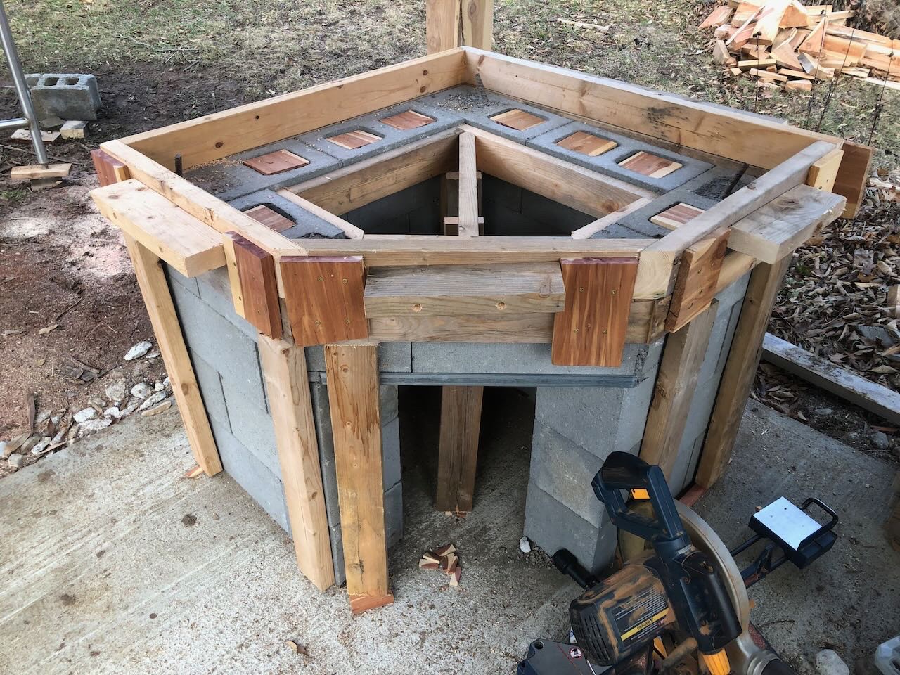

- 131 replies
-
- 11
-