Cathead
-
Posts
3,542 -
Joined
-
Last visited
Content Type
Profiles
Forums
Gallery
Events
Everything posted by Cathead
-
 Glen, What we might be seeing is the sternpost? Flattened to accept a rudder? That would explain the straight black bit that transitions into the curved lower part of the keel. As for lying "flat" and not at the angle of the slanted roof, it may well have support blocks that keep it "level". Why have a dinghy stored in such a way that it's predisposed to slide off a slanted roof? If you look close, you can even see where the upside-down gunwale hangs out over a shadow below that would fit as some kind of support block. It still looks strongly like a small boat to me.
- 457 replies
-
- 5
-

-

-
- sternwheeler
- Hard Coal Navy
- (and 1 more)
-
Keith, I'm away from home right now but in a few days I can mock up that view using one of my steamboats and see if I can help you see what I see.
- 457 replies
-
- 2
-
-
-
- sternwheeler
- Hard Coal Navy
- (and 1 more)
-
My first reaction is that it's the bow of a small boat, turned upside down. That's right where it might be kept. The white triangle is the shape of the hull, and the pipe/wire is simply the minor keel and its extension up the bow. There's enough room next to the pilot house to keep a little skiff and every vessel like this would have one.
- 457 replies
-
- 5
-
-
-
- sternwheeler
- Hard Coal Navy
- (and 1 more)
-
King, that's great to hear! It's a special place, to be sure. So glad my work is giving you good memories.
-
Sadly, my own hair is the wrong shade for scenic use. It's either too dark brown, or too white. My wife suggested I do a winter scene instead so I could use it. Ouch (I'm in my mid 40s, LOL).
-
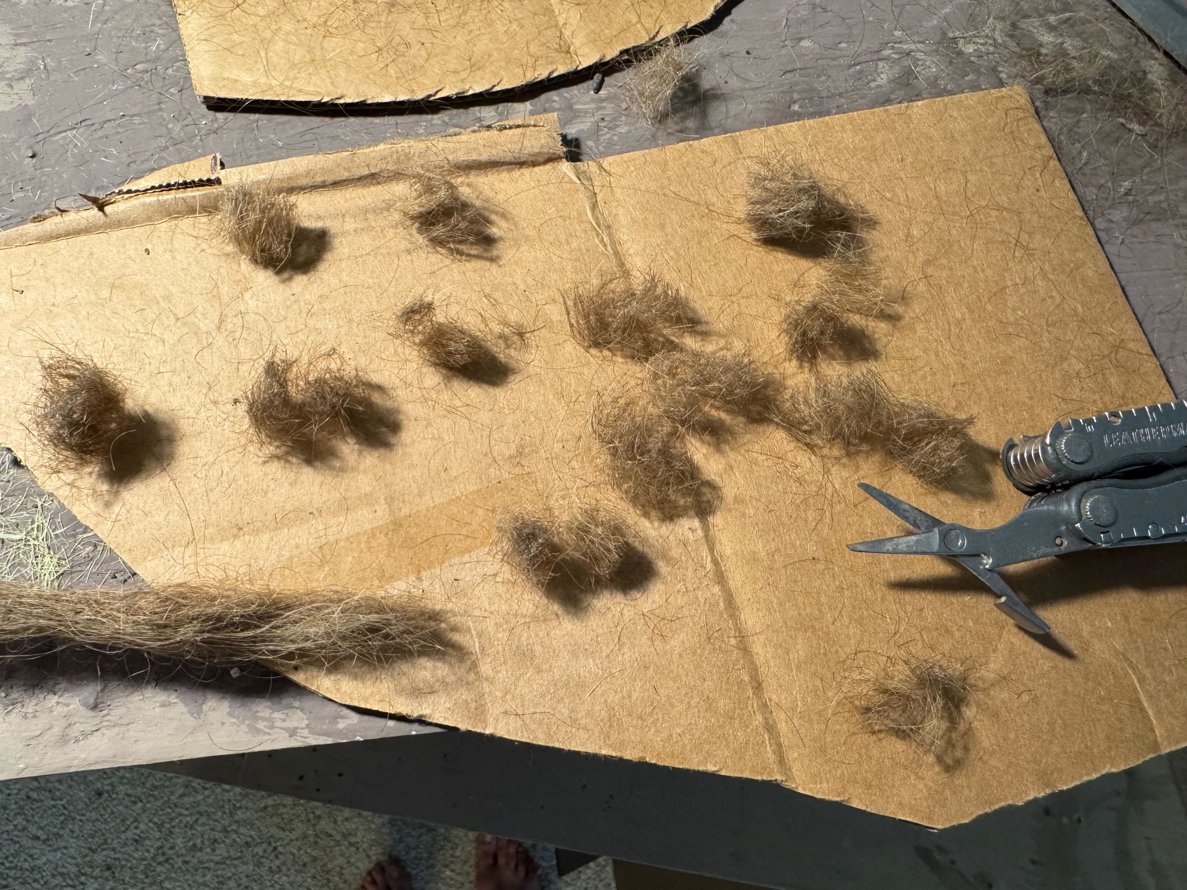
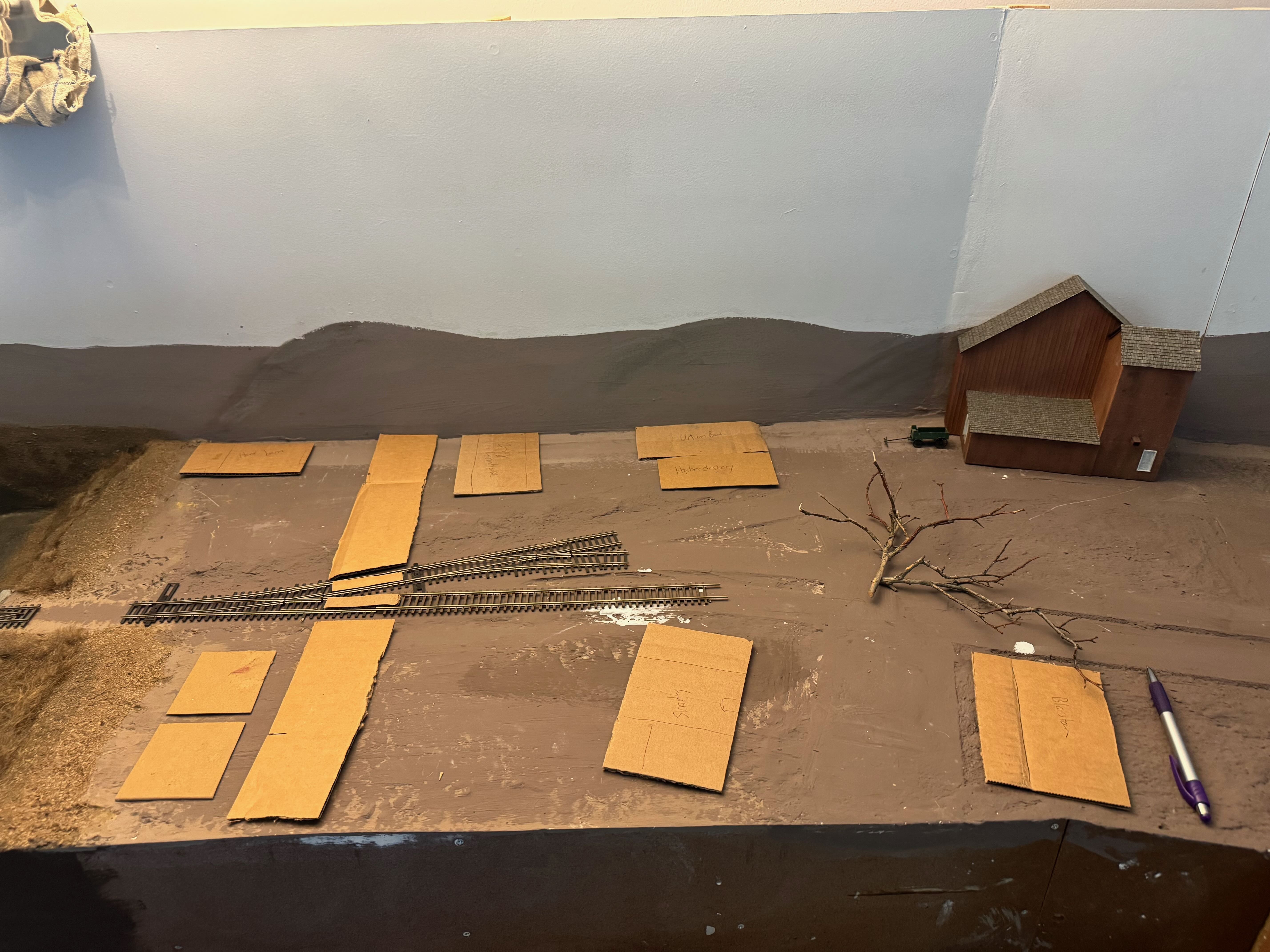
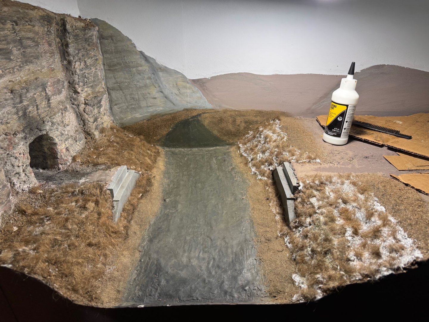
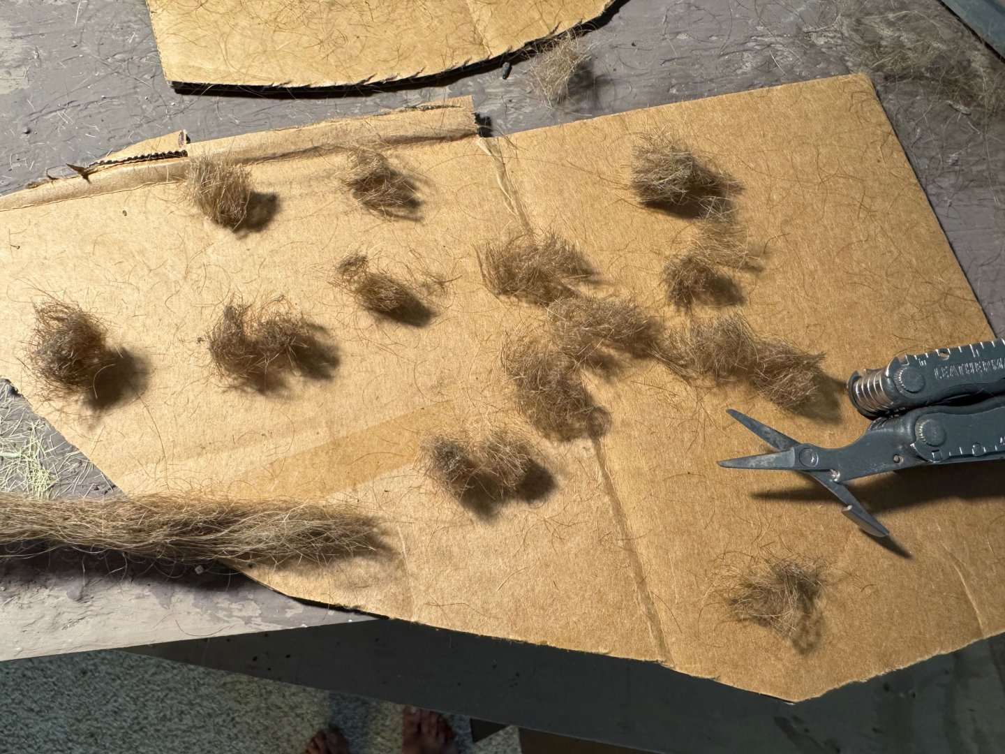
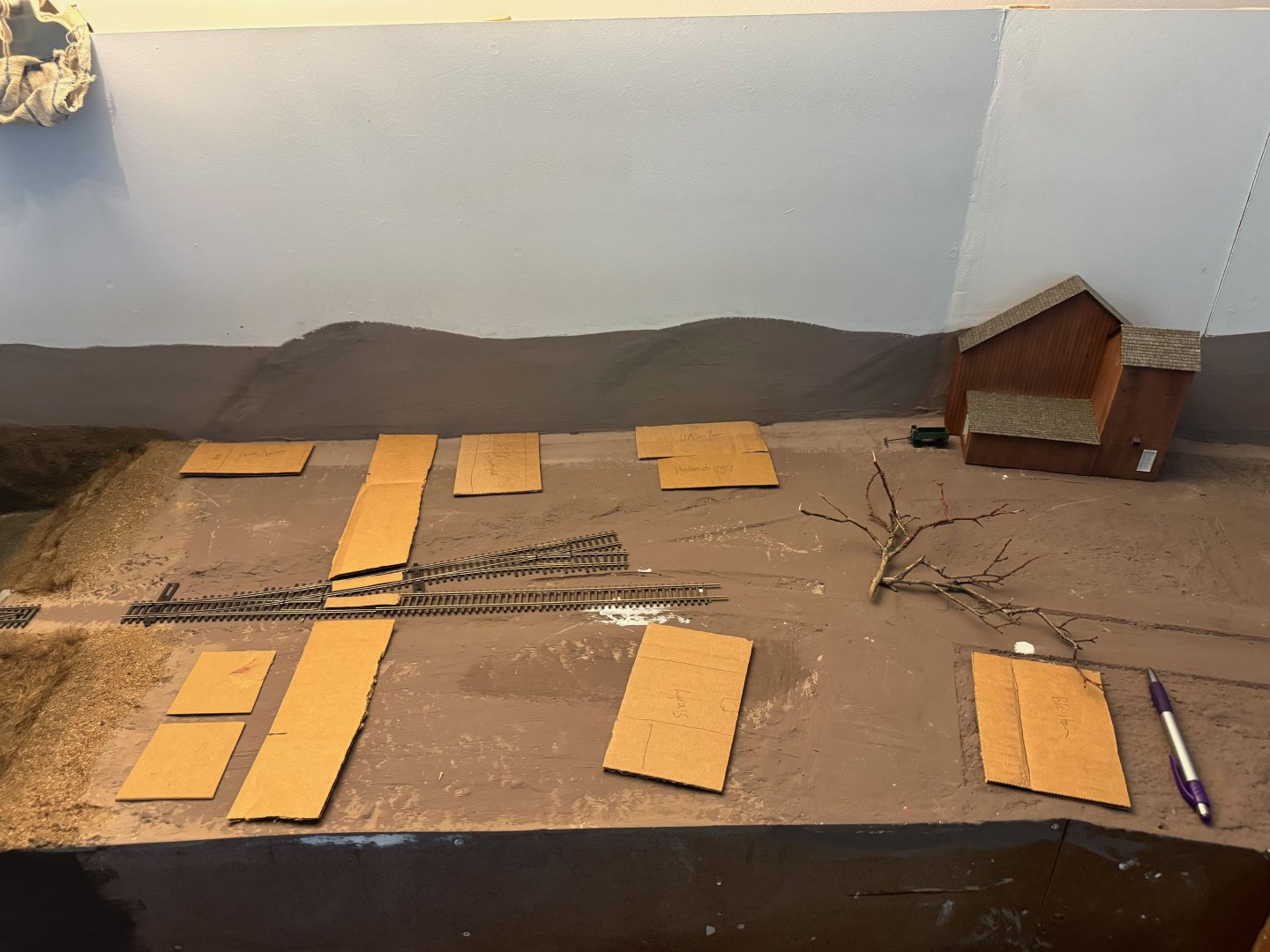
I decided it was time to start adding vegetation to the Moniteau Creek area. As a reminder, this area was pretty grassy/weedy/scruffy back then, with scattered bushes and a handful of trees. So I started with a layer of complex grasses. Modelers often use static grass for this, which is a product consisting of fine grains that are applied onto a glued surface and then made to stand up vertically using static charge. It actually works quite well, but my problem was that static grass doesn't come in the proper brown/deep yellow shade of late fall Missouri prairie grass. I also find that most manufactured scenery products never manage to have the subtle complexity in color and texture that natural materials do (just like the ground cover already used). But I found a really effective natural replacement that comes out like this: Any guesses? It's hair. Mrs. Cathead's hair, to be specific. Her hair color is nearly exactly the shades of dried Missouri prairie grass, and has all the natural complexity one could want in a scenery product. Here's how I used it. I took some clumps leftover from the hairbrush (we save some of these anyway for use in deterring garden pests like mice). I twisted lengths of hair into tightly wounded bundles, then cut them off into short clumps that stick together naturally. I then spread scenic glue on a patch of landscape and began planting the clumps, teasing them apart a bit to create the naturally even clumpiness of prairie grass while still covering most of the landscape. To emphasize this point, too many scenery makers assume that natural grass grows uniformly, like a lawn, but prairie grasses especially grow in tight clumps with space around their base. That pattern is actually essential to the survival of a variety of native animal species, but that's a different discussion. Here's a shot of one creek bank done, and of the broader area in various stages. The glue starts out white but dries clear. And one more view of a completed area: I really like the natural complexity in color and pattern this creates. It needs some bushes and woody growth to break up the pure grassiness, but it's a great start. I will be using static grass elsewhere in Rocheport, but wanted the creek banks to be especially wild and diverse in a way that static grass struggles to get right. If you're wondering, I haven't poured the creek water yet because I want to do most broad-scale scenery work first, to minimize the chances of dripping glue or color onto the finished water surface. I can give two other quick updates. One, here's the nearly finished bluff line on the east side, with mineral staining added. Here it's lit by a nice low-angle western sun. And the main Missouri River riverbank has had its scenic base layer of dirt and shredded leaves added, with the bluffs continuing on the backdrop downriver and the river itself having its base color added. And two, I've started experimenting with various arrangements of building footprints for the town. I'm having to compress a lot of visual interest into a small area so there are various ways to use specific buildings to highlight aspects of the real town. I'm mostly going to use laser-cut wood kits for all of these, probably scratchbuilding a few simple structures. I don't feel the need to build all the buildings to match real ones; the keystone "real" structures for the location are the grain elevator / hay barn and the depot. The rest can simply create the right era and feel. Someday I can always go back and scratchbuild specific town buildings but I really don't see the need to put that much time into such things up front. Hope my unorthodox scenery in this post wasn't too hair-raising. You can always comb through other build logs for more normal content. Thanks for reading!
- 292 replies
-
- 15
-
-

-
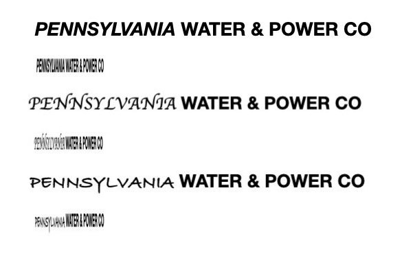
Keith, no worries, I've had my share of those! If it were me I'd use "Pennsylvania" as the most obvious option, and easier to understand for viewers of the model, accepting that the sign in the photo is unreadable and at worst it's a slight modification from reality that still reflects reality.
- 457 replies
-
- 4
-
-
-
- sternwheeler
- Hard Coal Navy
- (and 1 more)
-
Keith, Safe Harbor is a different dam & reservoir than Holtwood, and I doubt these vessels moved between reservoirs because there was no infrastructure to allow this; no locks at these dams. Unless the vessels were dismantled or otherwise somehow transported overland between the reservoirs, though that seems unlikely. The Susquehanna is not (and never was) navigable in the stretch these dams were built, other than once the reservoirs were in place. And each reservoir's power station was run by a different company. So if your vessel is marked for the Safe Harbor P&W Co then it never operated on Lake Aldred (Pennsylvania P&W Co). Yet you've got a photo of what we're assuming is the same vessel (from behind) that's marked as being on Lake Aldred. So to summarize: You have a rear view of a vessel marked as operated on Lake Aldred (PA P&W), assuming that caption is correct. You have a front view of a vessel with an unreadable name sign, and no captioning to indicate where it's operating. Unless I'm missing something? What's the source of the front-view image with the name plate? It doesn't appear in either of the links you gave in the first post. So if I'm thinking this through correctly, either: (a) It's the same vessel, in which case it's highly likely it was built and operated on Lake Aldred, meaning the name is likely for Pennsylvania P&W Co. as that's who operated that reservoir. (b) It's not the same vessel, in which case it's possible the front view is a different vessel built and operated on Safe Harbor, meaning the name sign could read Safe Harbor P&W Co. Both are plausible, as one can imagine a similar design being built multiple times once it proved to be operative on Lake Aldred (Safe Harbor was built years later). My personal leaning is that "Pennsylvania" is a better fit for the muddled lettering than "Safe Harbor", visually, though I wouldn't be surprised to learn that it's some third word. But it really doesn't look like "Safe Harbor" to me. Or I might be missing something. But that's how my mind is working through the logic at the moment.
- 457 replies
-
- 3
-
-
- sternwheeler
- Hard Coal Navy
- (and 1 more)
-
I'll suggest yet another reason for this, based on staring at it. I'm half-convinced that first word is written in a different font/style, more stylized than the straight block printing of "Water & Power Co". It's more scrambled than it should be for the perspective, if it was written the same. The letters seem closer together (less white space could be partly why it's harder to read). So in that model it could well be Pennsylvania in some italicized/hand-written/fancier non-standard script that's making it harder to read. I swear the lettering on that first word looks tilted or uneven as if it's a different "font" or style. That would honestly seem appropriate for this era, I could see "Pennsylvania" being stylized in some interesting way. Because I otherwise agree that the sources you give definitively state that (a) this vessel operated on Lake Aldred (impounded by Holdwood Dam, nee McCall's Ferry Dam) and that Pennsylvania Water & Power Co was doing the dredging for the power plant at Holtwood. I got obsessed with this question so ran a little visual test. Here are three version of that phrase printed differently. One with just italics on the first word, the second and third with more loosely formed scripts attempting to mimic a fancier script. Just below each is the exact same phrase at the same scale, just compressed horizontally to mimic the effects of forced perspective in the photo. Especially in the latter two, you can see how the simple block print of "Water & Power Co" stays legible but the first word gets harder to read. Now add in the actual effects of distance from the camera, weathering on the sign, etc. and it seems at least plausible that it really is Pennsylvania. This is rough, but just meant as a conceptual exercise to show how that first word could be distorted.
- 457 replies
-
- 5
-
-
-
- sternwheeler
- Hard Coal Navy
- (and 1 more)
-
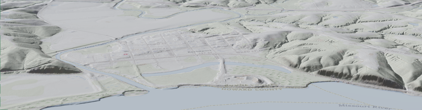
I realized I should probably give a labelled version of that 3D map, not assuming everyone knows/remembers the geography as well as I do. So here it is for comparison with the broad layout view:

-
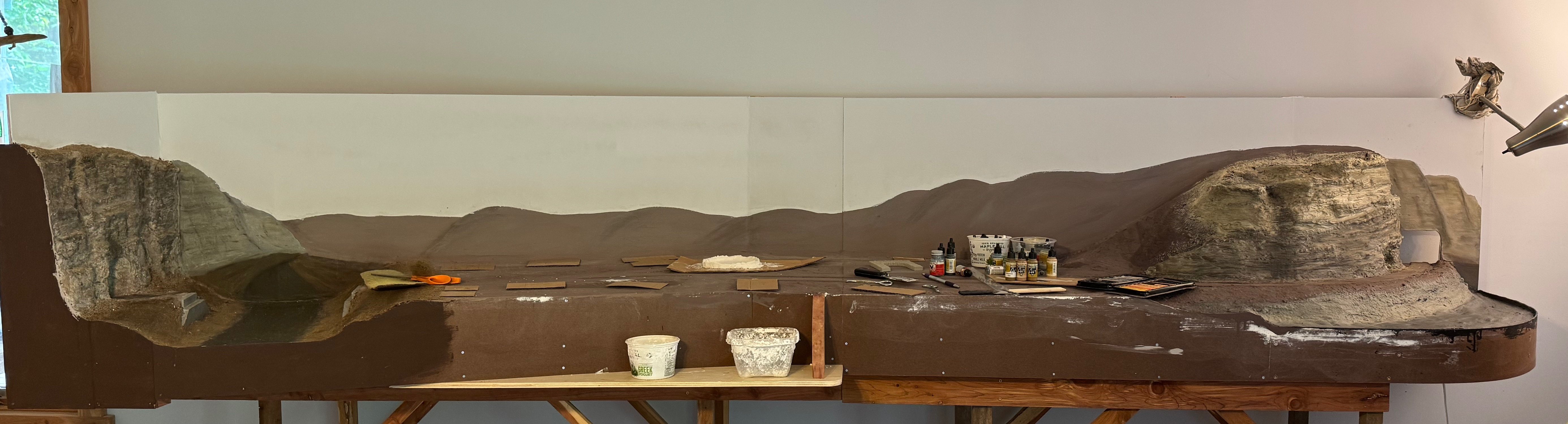
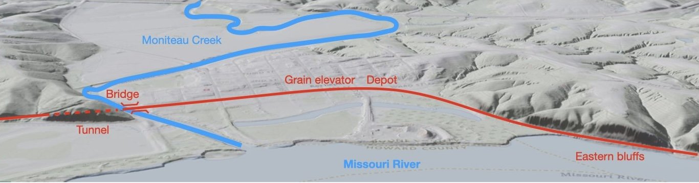
So here's a low-angle 3D view of the landscape at Rocheport, looking north at roughly the same perspective the viewer of the layout has. This is taken from the US Geological Survey's National Map online map data server, something I use all the time in my day to day work. From left to right, you can follow the rail line through the tunnel at the nose of the left-hand ridge, across the bridge over Moniteau Creek, through the town of Rocheport on the flat riverbottoms between the two lines of hills, then back to the sheer bedrock bluffs along the Missouri River at far right. And the reason I share this, is that here is the current layout's version of that view: You can see that I've started painting the backdrop as well, giving rough shape to the line of hills framing the Moniteau Creek valley in the background and giving the scene some depth. Maybe this helps give some more geographic context to what I'm building here. If you're wondering, the bluffs on the right side are quite a bit shorter than the real thing; I simply don't have vertical space to build them to scale, and even if I did they'd probably look fake. This height uses the principle of selective compression, as does so much of model railroading, to give what I think is a proper sense of scale and proportion that "feels" right. Same for the horizontal compression of Rocheport, which has a far longer distance between the two bluffs than I can include here, but I've planned the town's layout to include enough signature features so that it'll "feel" right. Hope you enjoy these shots. I'm getting relatively close to being comfortable with the idea of actually laying tracks and being able to operate a train through here, which will be a very exciting development. Thanks, as always, for all the various expressions of interest and support!
- 292 replies
-
- 12
-
-
-
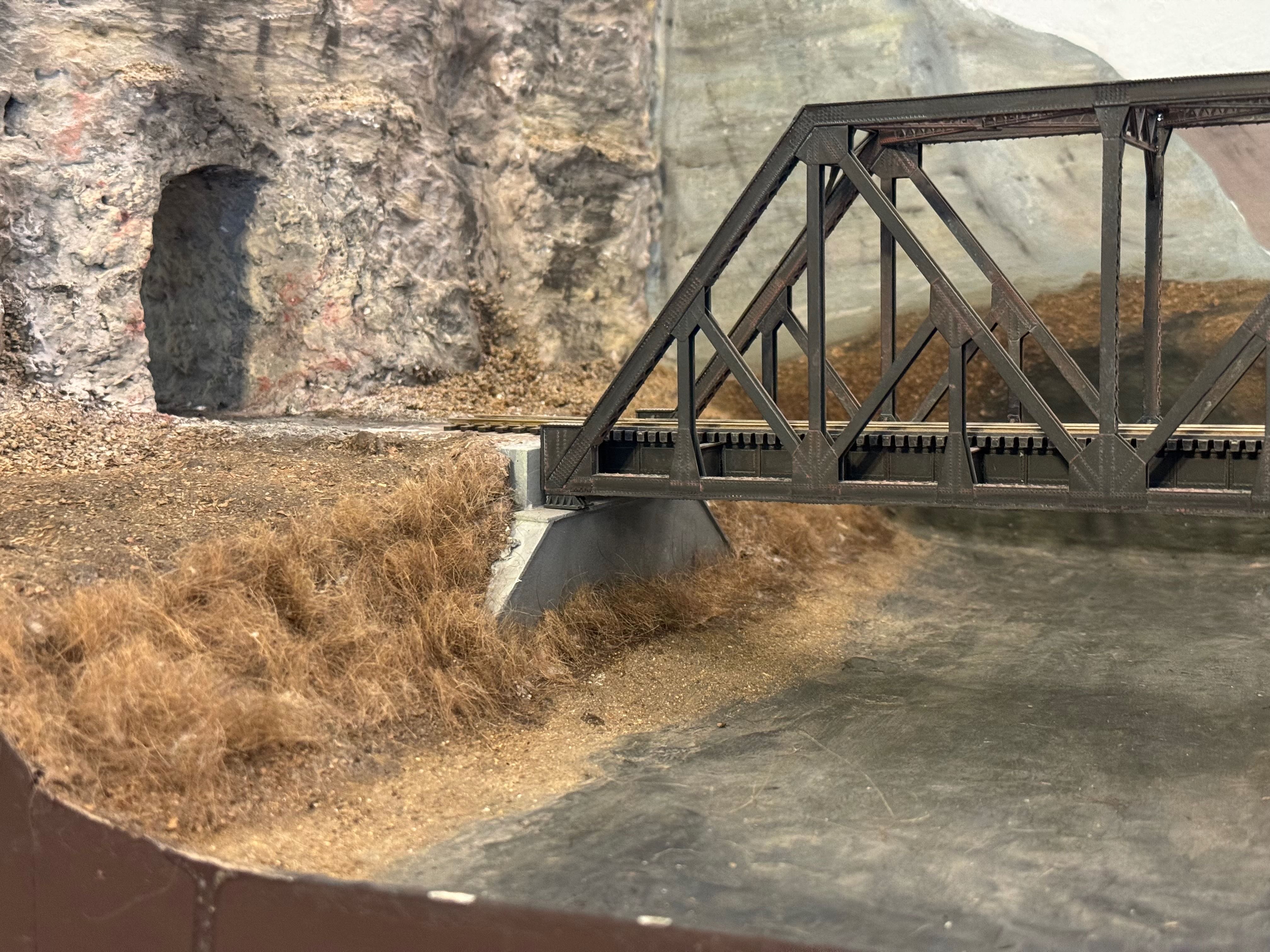
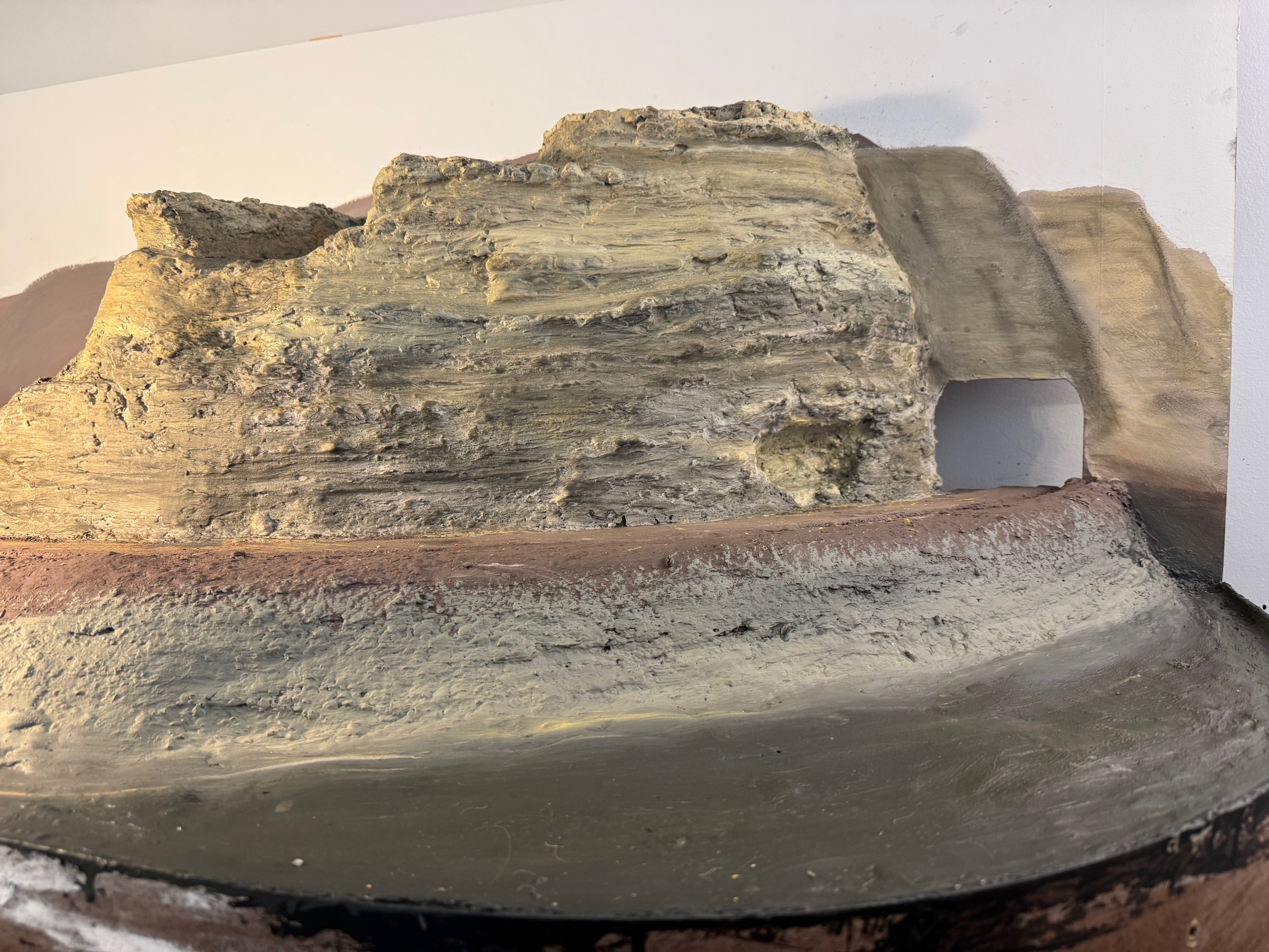
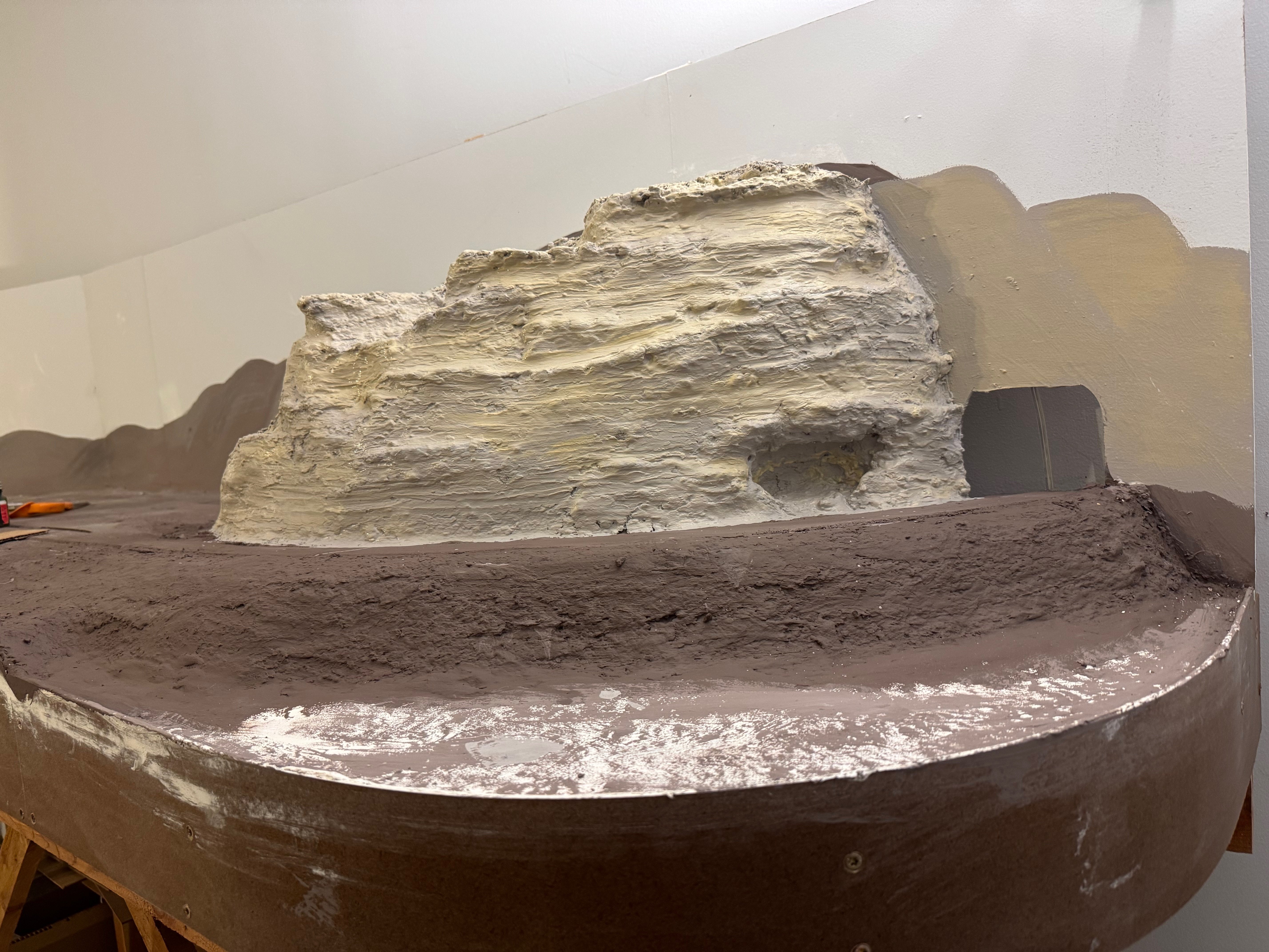
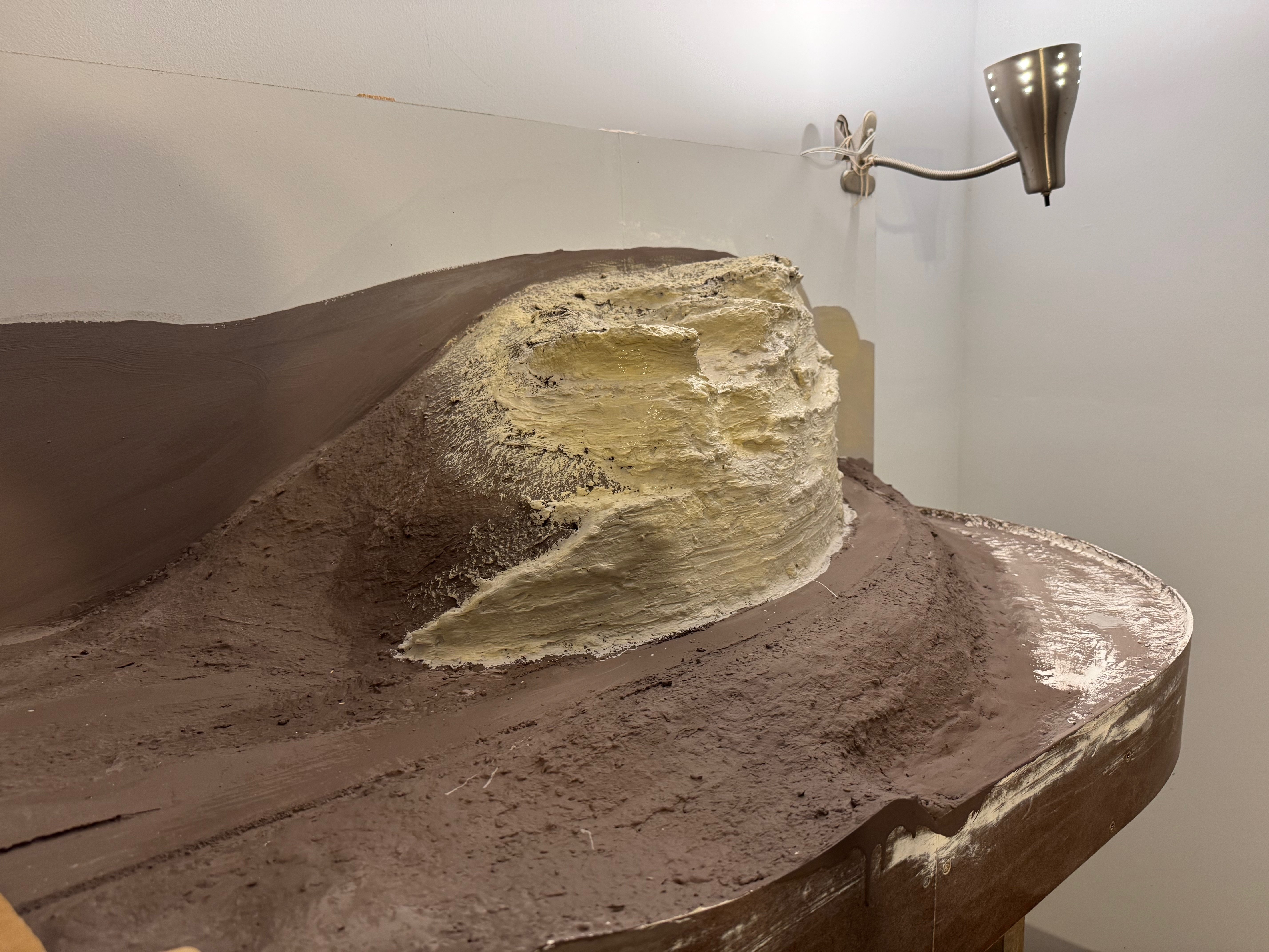
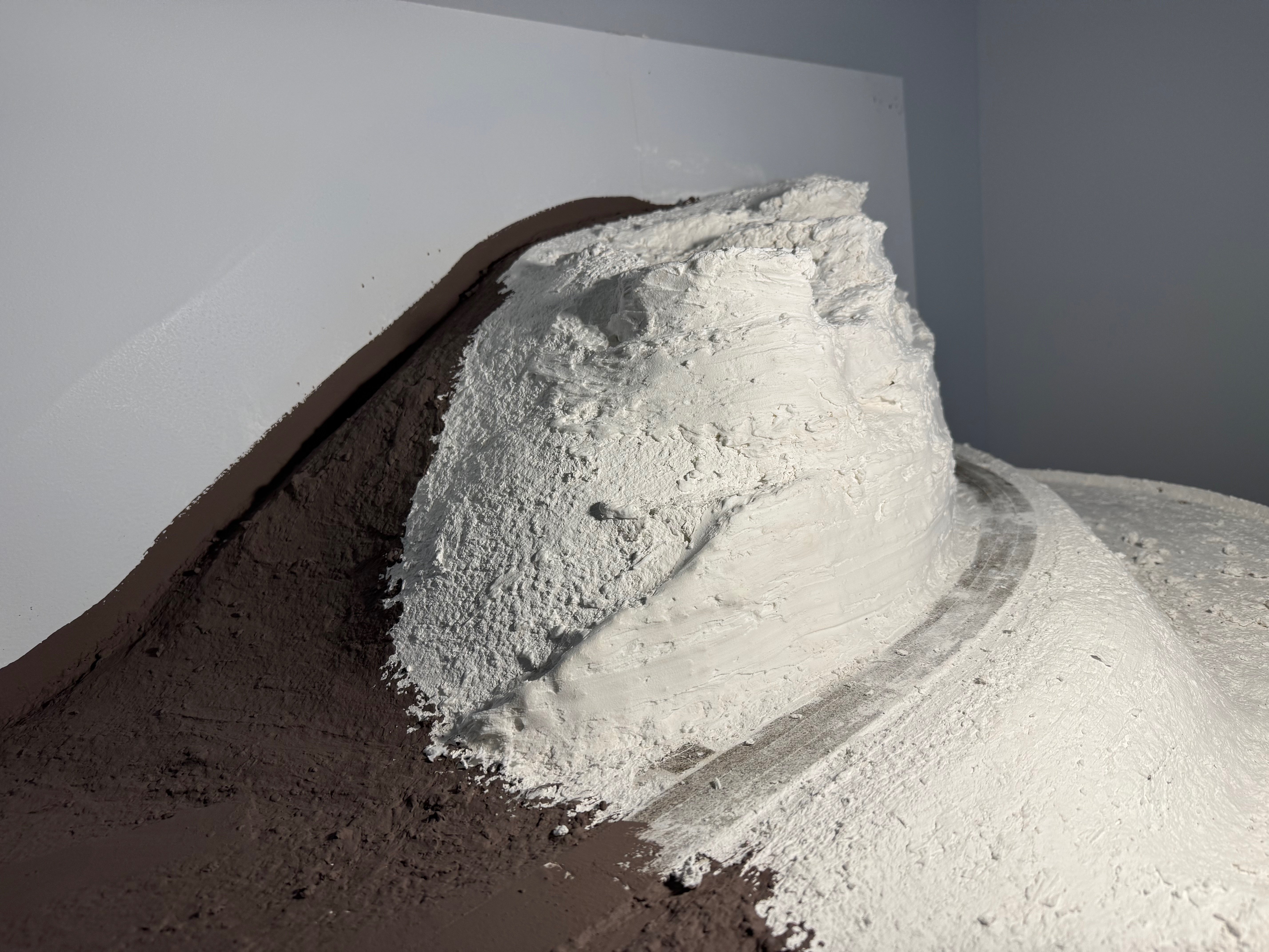
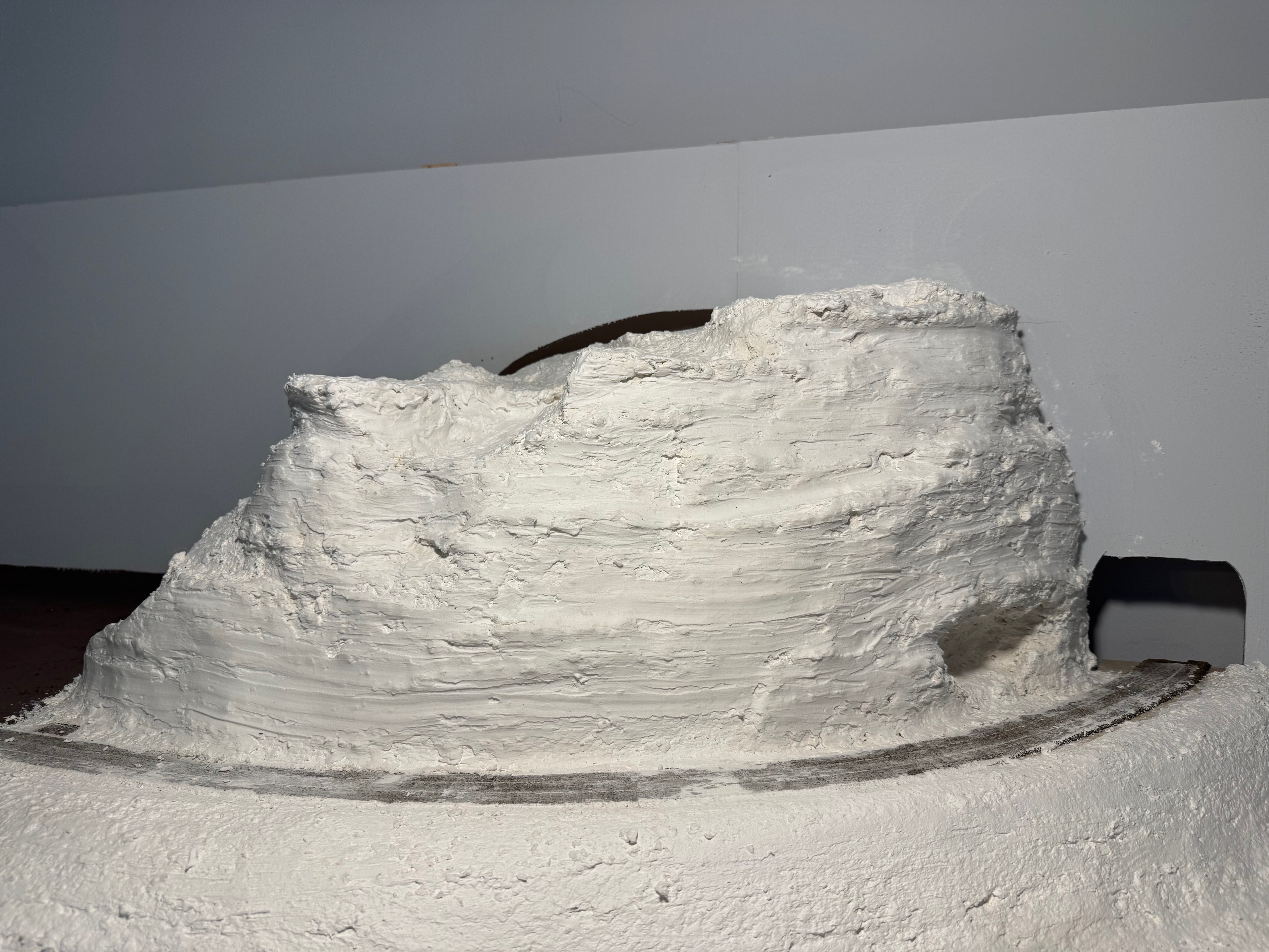
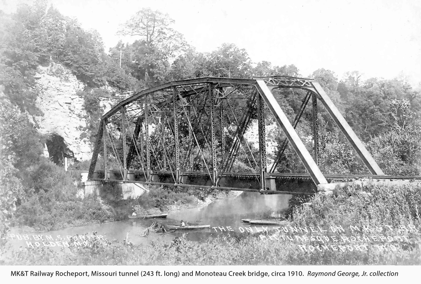
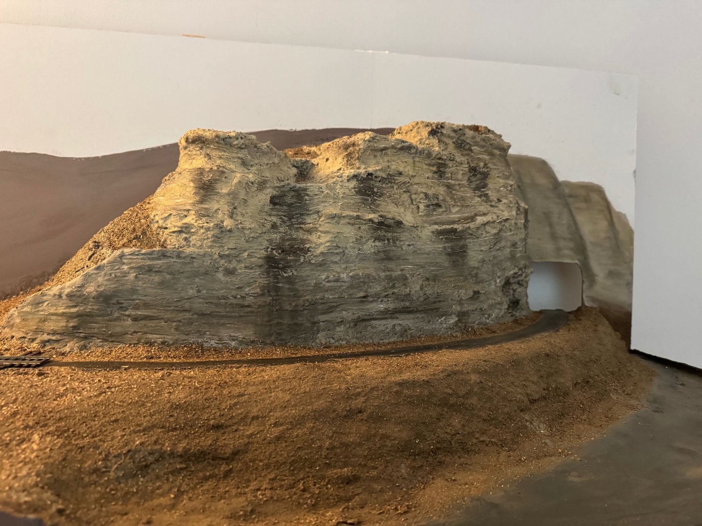
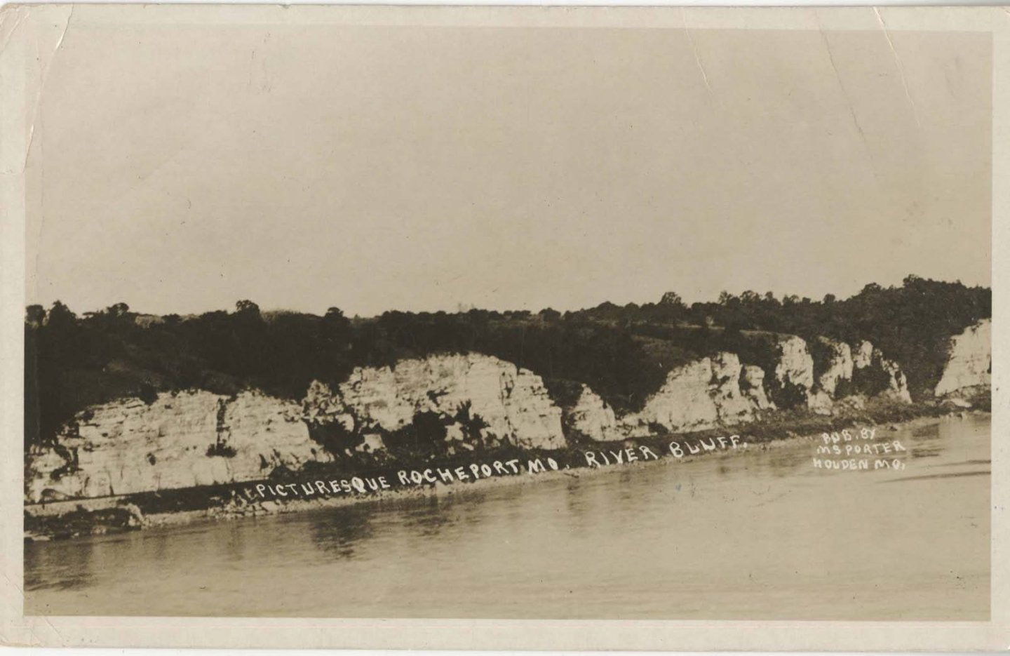
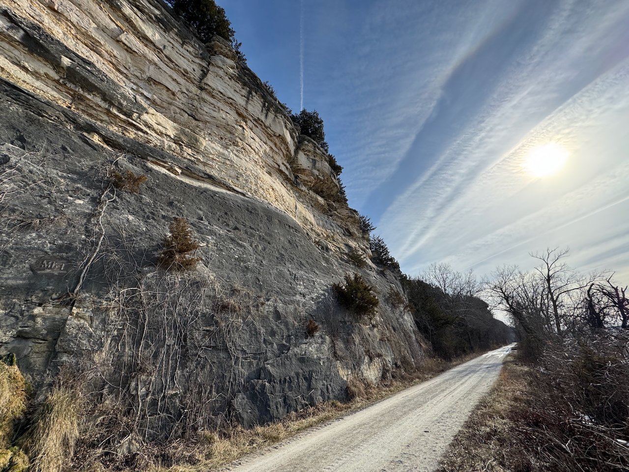
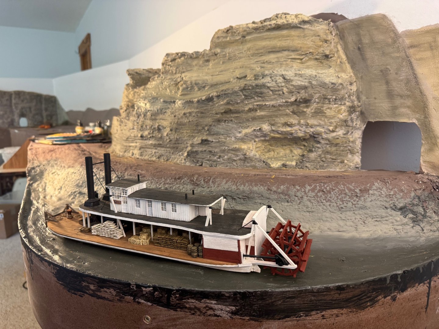
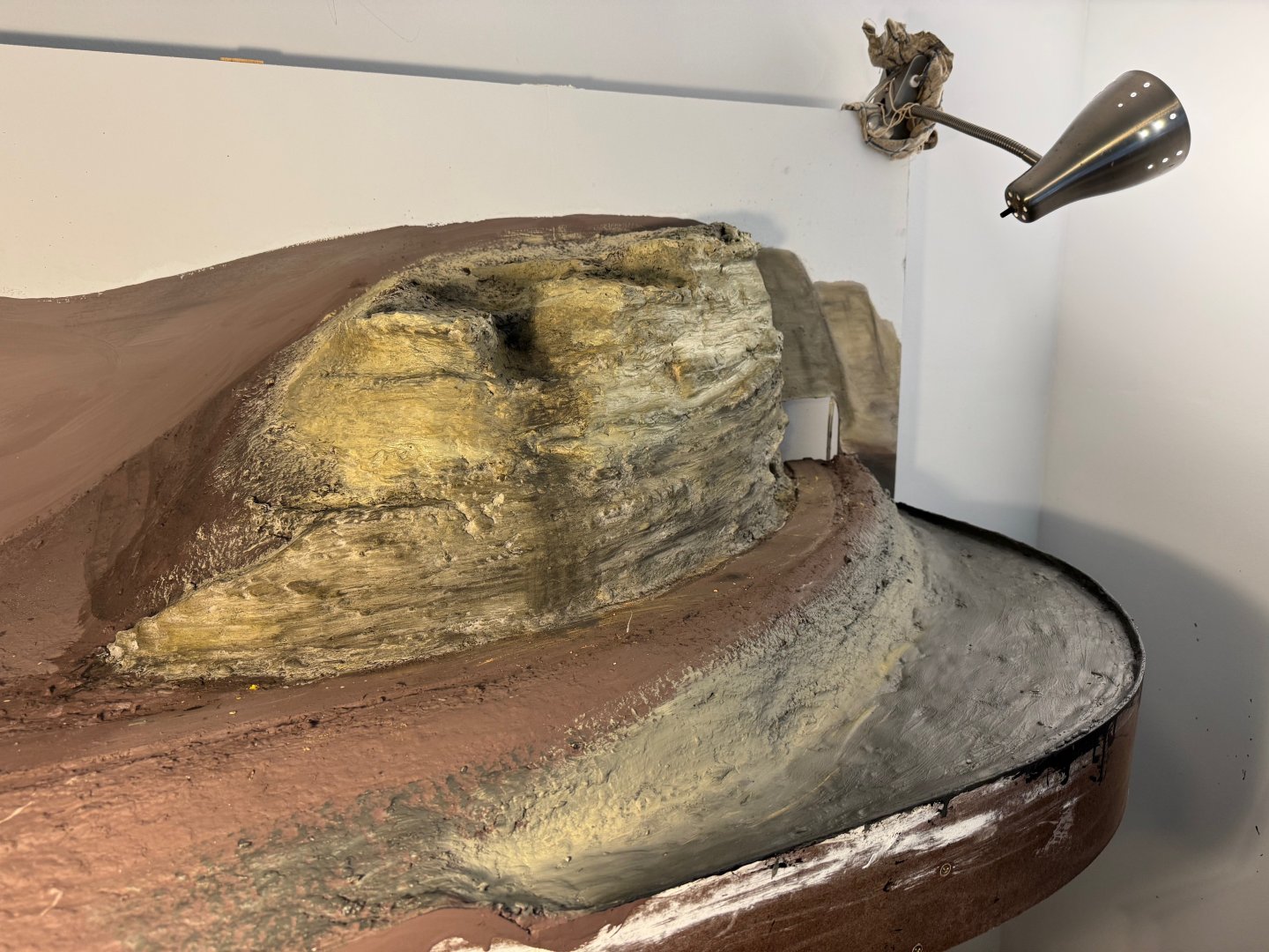
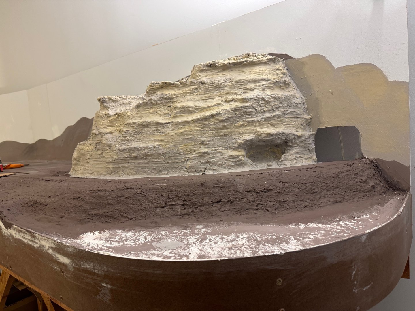
OK, here's a broader update covering the last week or so. I've been filling in the bluff line to the right with plaster and base color layers. Base plaster layer shaped into rock faces and outcrops: Early paint layers: Adding more color complexity: And since this is Model SHIP World, here's a reminder that this whole scene was inspired by Peerless operating on this stretch of the Missouri River. Right now this all still looks like Montana, not Missouri, in the absence of vegetation. But it's coming along. I'm not done with bluff coloration, I'm still planning to build up more color complexity and texture, as on the tunnel bluff. Here's a reference shot as a reminder: And a historical reminder: In the next post I'll share an interesting broader view.


- 292 replies
-
- 11
-
-
Welcome back! Those shots of crowded boats are fun.
-
It honestly looks like something a model railroad company would invent as an overly quirky layout detail.
- 457 replies
-
- 5
-

-
-
- sternwheeler
- Hard Coal Navy
- (and 1 more)
-
As we've discussed privately, I have some personal history along this part of the Susquehanna and am very excited to see this build come to life!
- 457 replies
-
- 2
-
-
-
- sternwheeler
- Hard Coal Navy
- (and 1 more)
-
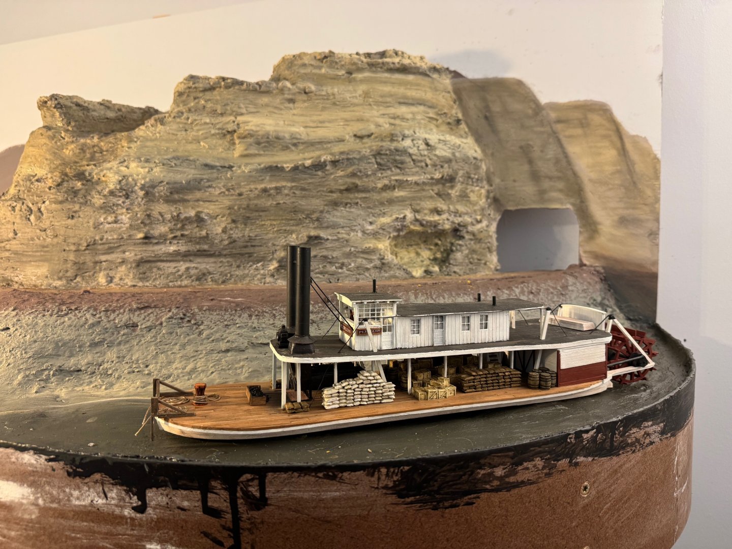
I will need to dredge up more superlatives for this one. You've done such an amazing job of taking a really unique, interesting prototype and making it into something even more unique and interesting. I feel like I can review these photos over and over again, still finding new details to enjoy. This log has added a lot of joy to my life and I thank you for all of it.
- 732 replies
-
- 4
-
-
-
- Lula
- sternwheeler
- (and 1 more)
-
Less mineshaft, more tunnel.
-
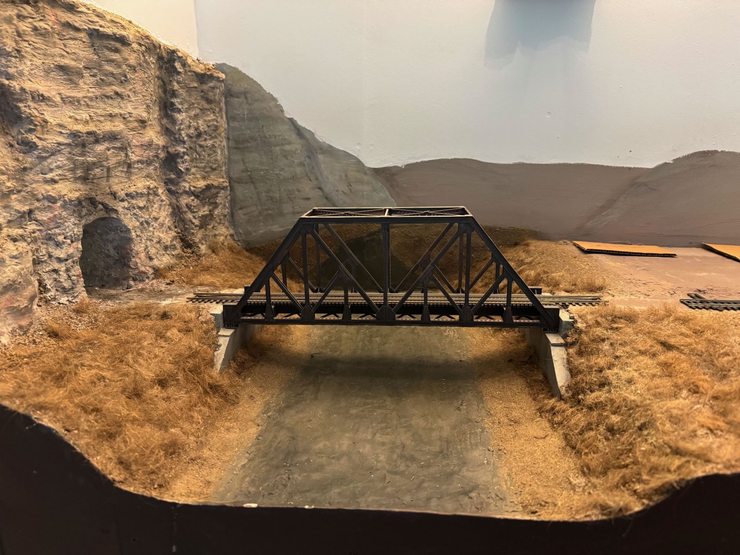
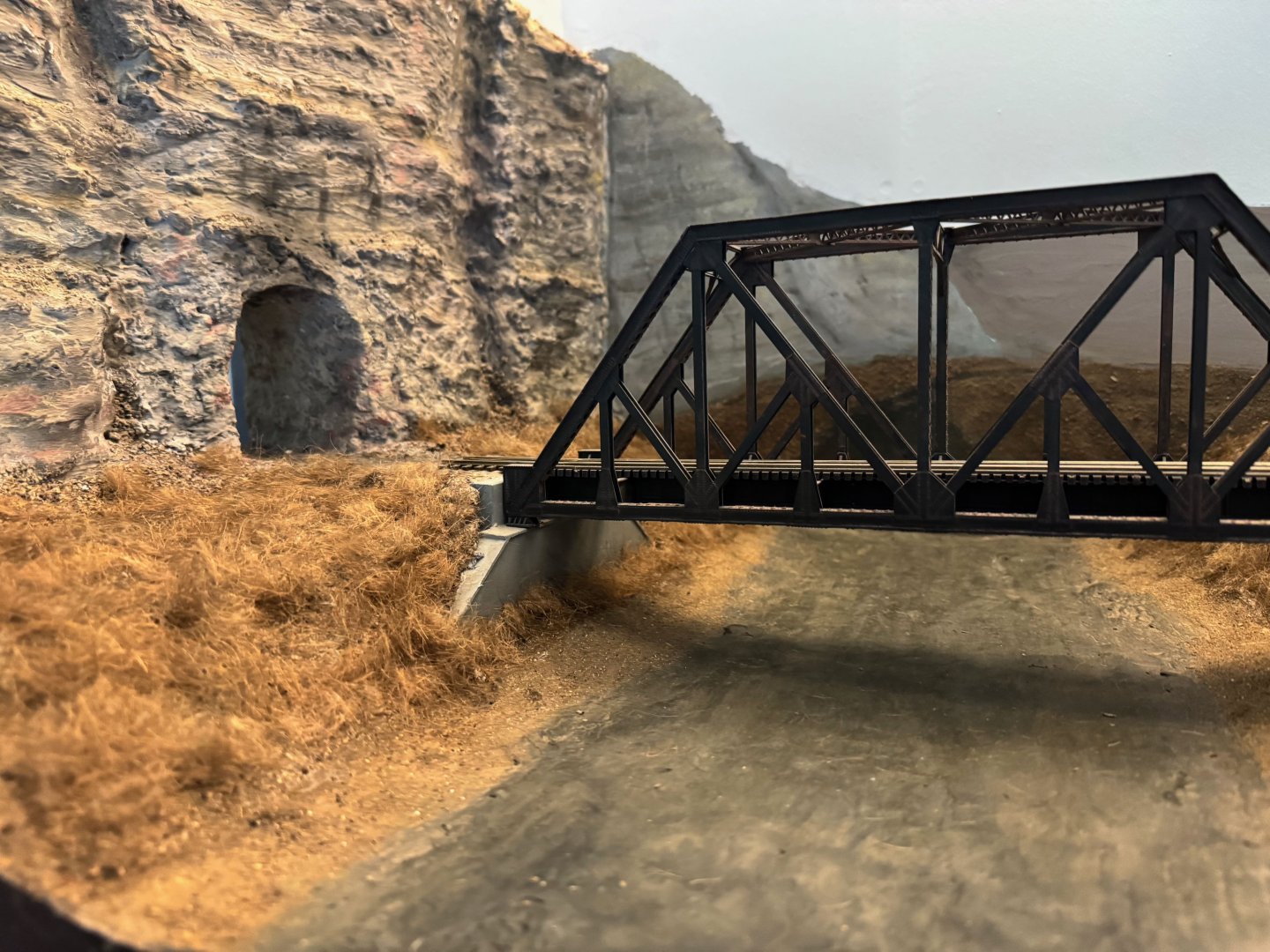
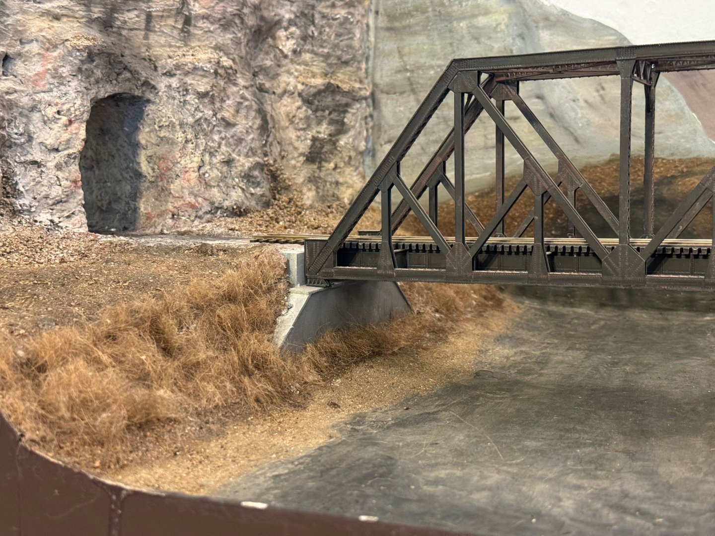
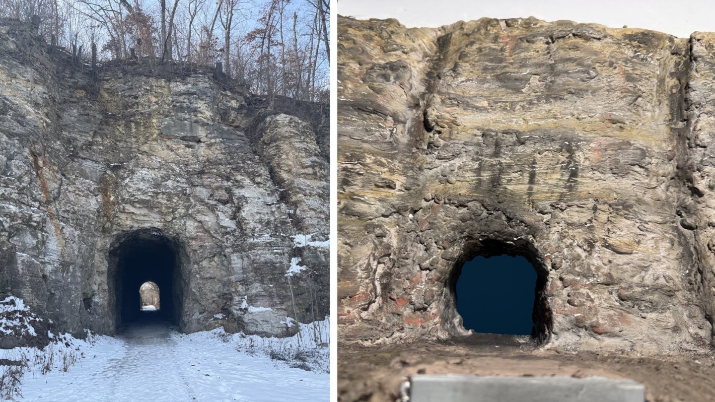
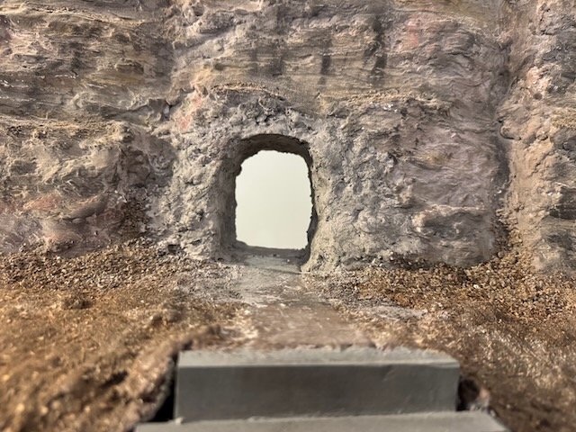
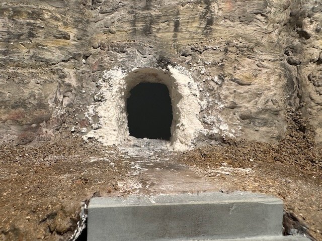
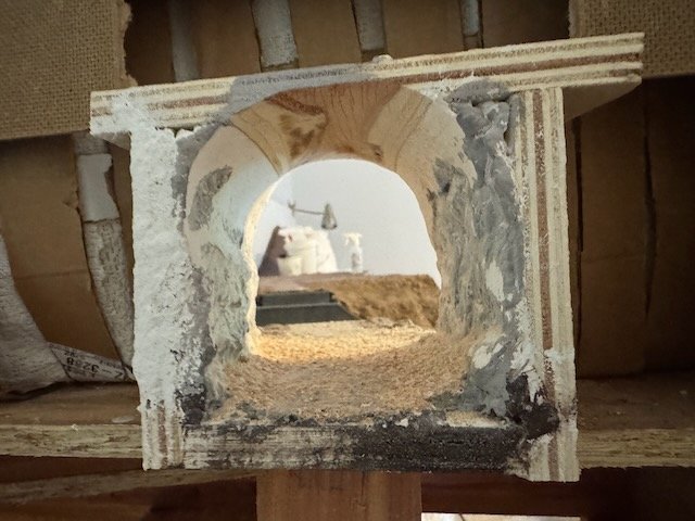
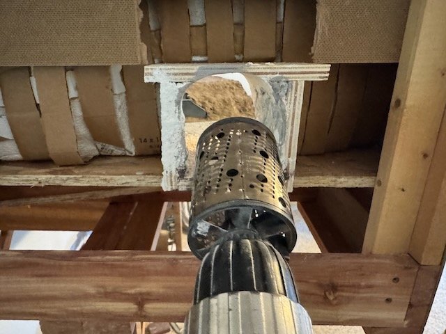
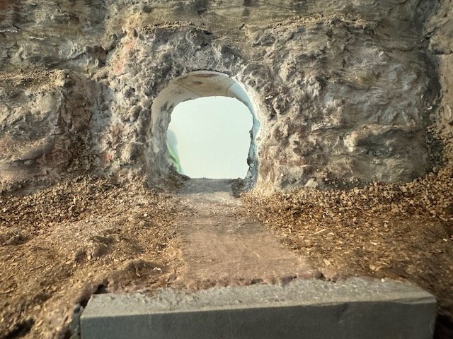
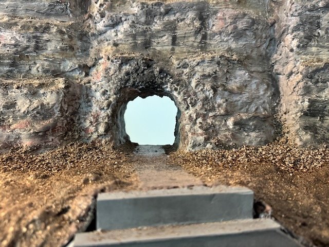
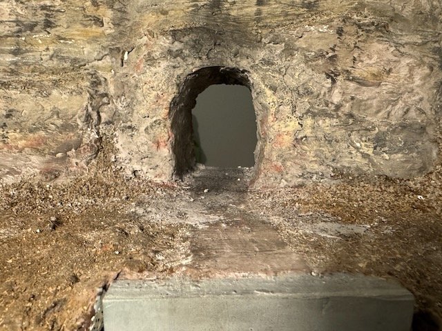
I've made broader progress that I'm not quite ready to write up yet, but here's a narrower update on a minor upgrade. The shape of the tunnel has been bugging me; it seems too squat. It wasn't really obvious to me until I'd finished the bluff, but now I can't un-see it. I think you can see what I mean in the paired photo below. The real one is significantly rectangular; mine is nearly square. Bugs me. So I decided to renovate it. This meant raising the ceiling and narrowing the sides. Starting point: I used a woodworking tool I had in a drawer, a rotary rasp that chucks into a power drill. It's meant for rough shaping of wood, but boy is it perfect for boring out a tunnel. Then I filled in the sides with some new plaster. Gave it a fresh base coat of paint: And weathered it down: That's much better. The beauty of this is that I'm modeling the period not long after this tunnel was freshly blasted. So it's actually perfect to have the area right around the portal look a little disrupted and different from the rest of the rock. I didn't weather it quite as much, leaving the color a little fresher. I'm pretty pleased with how this came out. Just shows it's worth going back and reassessing your work now and then. I've also been working on the longer bluff line on the other end of town, along the river, but am not quite ready to share that progress yet. Thanks for the fun discussions above, and for all your interest!
- 292 replies
-
- 15
-
-
-
I'm enjoying the thought and creativity you're putting into this build. Making a build your own is what makes it not "yet another Endurance"!
-
This model is simply a cat-alogue of excellent work. Littered with interesting features, and the hull has lovely fe-lines. One might even say purr-fect.
- 732 replies
-
- 7
-
-
-
-
- Lula
- sternwheeler
- (and 1 more)
-
That's looking really nice.
-
That wide rail seems like a necessary piece of infrastructure enabling the stable placement of adult beverages as needed.
- 732 replies
-
- 4
-
-
- Lula
- sternwheeler
- (and 1 more)
-
Not something I'm very experienced in, but as no one else has answered...I've seen a couple different approaches used. Some folks shape their masts from square stock, which lets them produce both rounded and other forms on the same piece (much like the real process). You could certainly build it up as well.
-
I managed to overlook this update somehow, but a belated congratulations on finishing. You've done a nice job bringing this kit to life and it's a lovely gift for your friend.
- 56 replies
-
- 2
-
-
-
- Lindberg
- sternwheeler
- (and 1 more)
-
As you can tell from my username and photo, I heartily approve of this addition to the crew.
- 732 replies
-
- 6
-
-
-
- Lula
- sternwheeler
- (and 1 more)