Cathead
-
Posts
3,058 -
Joined
-
Last visited
Content Type
Profiles
Forums
Gallery
Events
Everything posted by Cathead
-
 One more question to address is that of stability, related to passengers moving around decks without railings. While as far as I know there were always railings around elevated passenger areas, it's also the case that these boats were pretty stable. It was routine to load Western river steamboats until their main decks were only a few inches above the river, telling you that they weren't expected to pitch or roll much. It's quite possible for strong winds to whip up waves (even whitecaps) on the Missouri River, and strong winds were the cause of quite a few steamboat wrecks, but the baseline operating conditions for these vessels were pretty stable compared to any open-water sailing. They had a low center of gravity and, especially by 1893, generations of knowledge regarding how to build stable vessels on the Missouri. Railings are sensible in any raised area where non-crew are present, but in this context probably more for general constraint than specifically for vessel motion.
 -
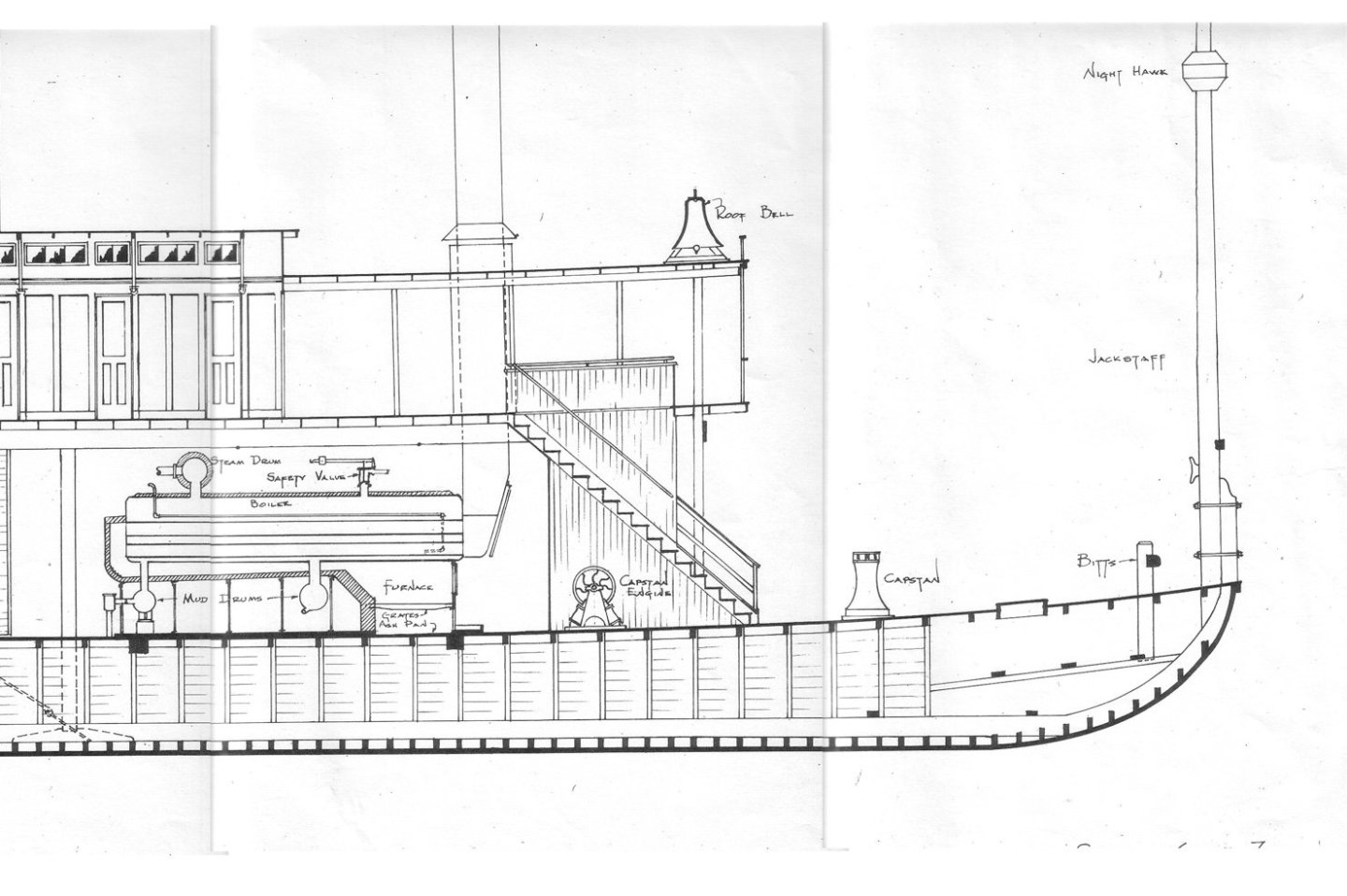
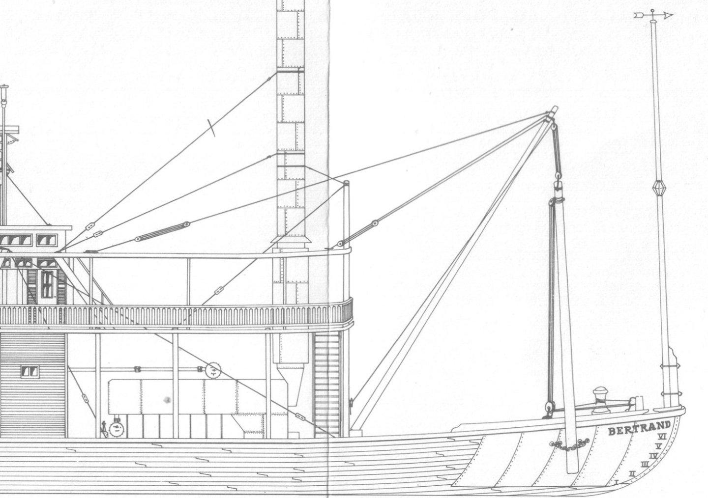
My goodness, that question sparked quite a discussion! Unfortunately that kicked off right when I went into a really busy stretch and couldn't keep up. Let's see if I can unpack it all. Stairs vs. ladders My strong impression, from extensive reading/research, is that between-deck ladders were rarely used on Western river steamboats. I can't recall seeing a photo with a ladder and every photo or plan I can recall has stairways between decks. I skimmed various references I have on hand and found nothing to counter this. Keith, thanks for your detailed thoughts, but I can't convince myself of the ladder you suggest in that photo. Moreover, the location of the man & child standing in front of the potential ladder strikes me as much farther forward than you indicate; to me they're standing directly under or just fore of the pilot house. That would be a very inconvenient place for it; emerging under the pilot house is impossible, and just forward of the pilot house there's no sign of any protection around the "hatch" that would be necessary. My personal opinion is that a stairway is far more likely and that I need to determine where it was. I continue to lean toward the location I identified at the end of my post and plan to build a cardboard mockup to test out the idea. I don't know why Peerless wasn't constructed with a forward stairway in the first place, like most steamboats, but one possibility is that she was built to be a cargo-only boat. By the late 1890s passenger river travel would have declined quite severely, and Peerless was likely initially intended to be that era's equivalent of a local towboat, handling local bulk cargo for areas not yet served by railroad but not really set up for long-distance passengers. As noted above, the boiler deck is where passengers would be carried, but (a) her cabin looks too small to accommodate more than a handful of passengers, (b) she has no outhouse hanging off the stern end (above the wheel) where passengers' needs would normally be accommodated, and (c) there are no railings along the boiler deck as in any boat I know of that carried passengers. And if she was designed for freight only, then there would be little reason to have a passenger-convenient forward stairway right in the way, when you could just tuck a crew-only stairway somewhere back in the engineering spaces. We do have photos of her hosting jaunty outings in this era, and it's possible a decline in freight due to the building of the MK&T railroad along the north shore of the river pushed her owners to diversify, but such outings would have occurred when she wasn't carrying freight, so passengers could remain on the main deck while the vessel was in motion. As someone noted above, the only photos we have of people crowding the boiler deck are taken when the vessel is clearly stopped and staging a photo shoot. Chimneys (stacks) To the best of my knowledge, based on references such as Alan Bates and various plans, steamboat chimneys had heat shielding jackets placed around them from the boilers as far up as passengers were likely to encounter them. For example, here are two different plans for Bertrand, both of which show heat shielding around the chimneys as far back as her 1856 construction date. Note that these extend through the boiler deck (one above the main) to the roof of the hurricane deck (two above the main). The boiler deck was the main passenger area so the shielding was certainly relevant there. Passengers would normally not be allowed on the hurricane deck, so there the shielding ends as soon as the chimneys pass through the deck (also because above that the hot chimneys don't encounter anything flammable). In addition, Model Expo's Chaperon (1884) kit also clearly includes heat shields around the chimneys, with the instructions stating "There are two 1" diameter dowels, 2-5/8" long in your kit. These are the smoke stack covers. They were sheet metal cylinders that surrounded the smoke stacks to prevent the crew from coming into contact with the hot stacks." See quote on page 8 (link above) and accompanying Photo 12. Kurt Van Dahm's detailed publication on building Chaperon also clearly documents this heat shielding. So I think it's pretty conclusive that chimneys had heat shielding on their lower stretches, usually until they'd passed through the final deck. Above that they came into contact with nothing but guy wires and nobody but crew, who had to take their chances. No doubt it was still a hot place to stand during operation, but it clearly wasn't too much of a problem since standard steamboat design had the shielded chimneys passing right through what must have otherwise been the most popular outdoor passenger location (view forward, access to whatever breeze was available). Chimney painting This is a fun question that I had not thought about before. My initial reaction was the same as Brian's, that the identifying bands of city-class gunboats were painted directly on the chimney, not on any special heat shielding. All photos I can find seem to bear this out. My guess is that, by the time hot gases had made it that far up the chimney, they (and the surrounding metal) were cool enough not to blister paint off. Steamboats had very long chimneys to increase the draft of their boilers, and it seems to me that intense heat would bleed off quickly with height. But you'll notice that all the identifying bands of city-class gunboats were painted very high up the stacks; I'd always assume this was simply for visibility, but there's likely a convenient coincidence that this also minimized any heat-related degredation of the paint. A very neat insight if true! Wow that was a lot to think and write about. Further thoughts?
- 259 replies
-
- 10
-

-
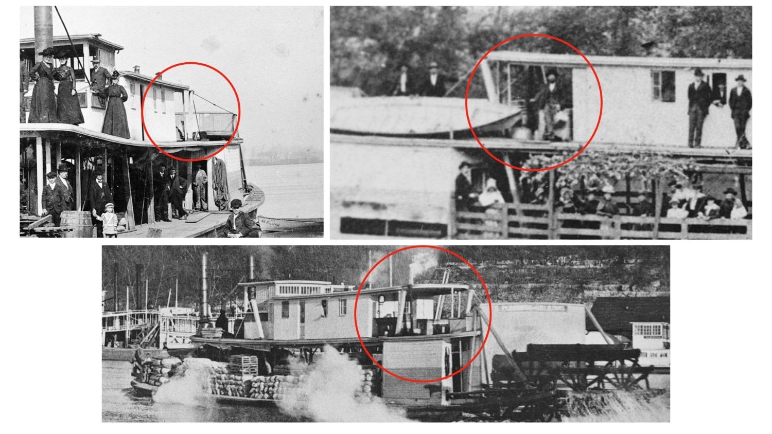
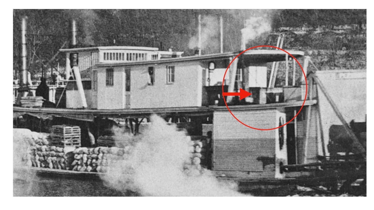
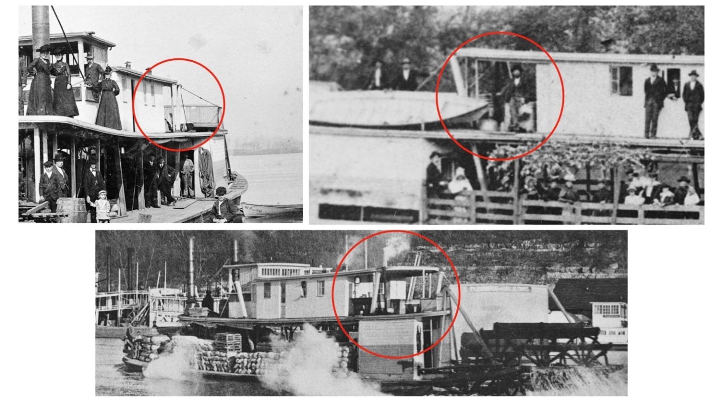
Wefalck, thanks for checking on that. The image you reposted shows a later retrofit to add those stairs; they're not there in the original configuration. See the image I posted above that for comparison (and the descriptive captions), or consult the array of images presented in the first post of this log. Brian, I thought about that, too, as it seems the next most logical place. The problem is that I don't see any sign of railings protecting a stairway under that covered "awning". There also appears to be a door at the rear of the boiler deck cabin, right on the center line. For example: Funny, as I was writing and posting that, I suddenly saw that bottom-most photo in a different way. Is what I took for a large crate actually a solid-walled enclosure for a staircase, leading up perpendicular to the hull, starting near centerline in front of the engine room and coming out on the starboard side of the boiler deck? If so, that's why you don't see an enclosure in the photo at upper right, because the man standing within the red circle is standing in front of the opening down to the stairs, not alongside stairs running fore and aft. Here's a closer closeup:

-
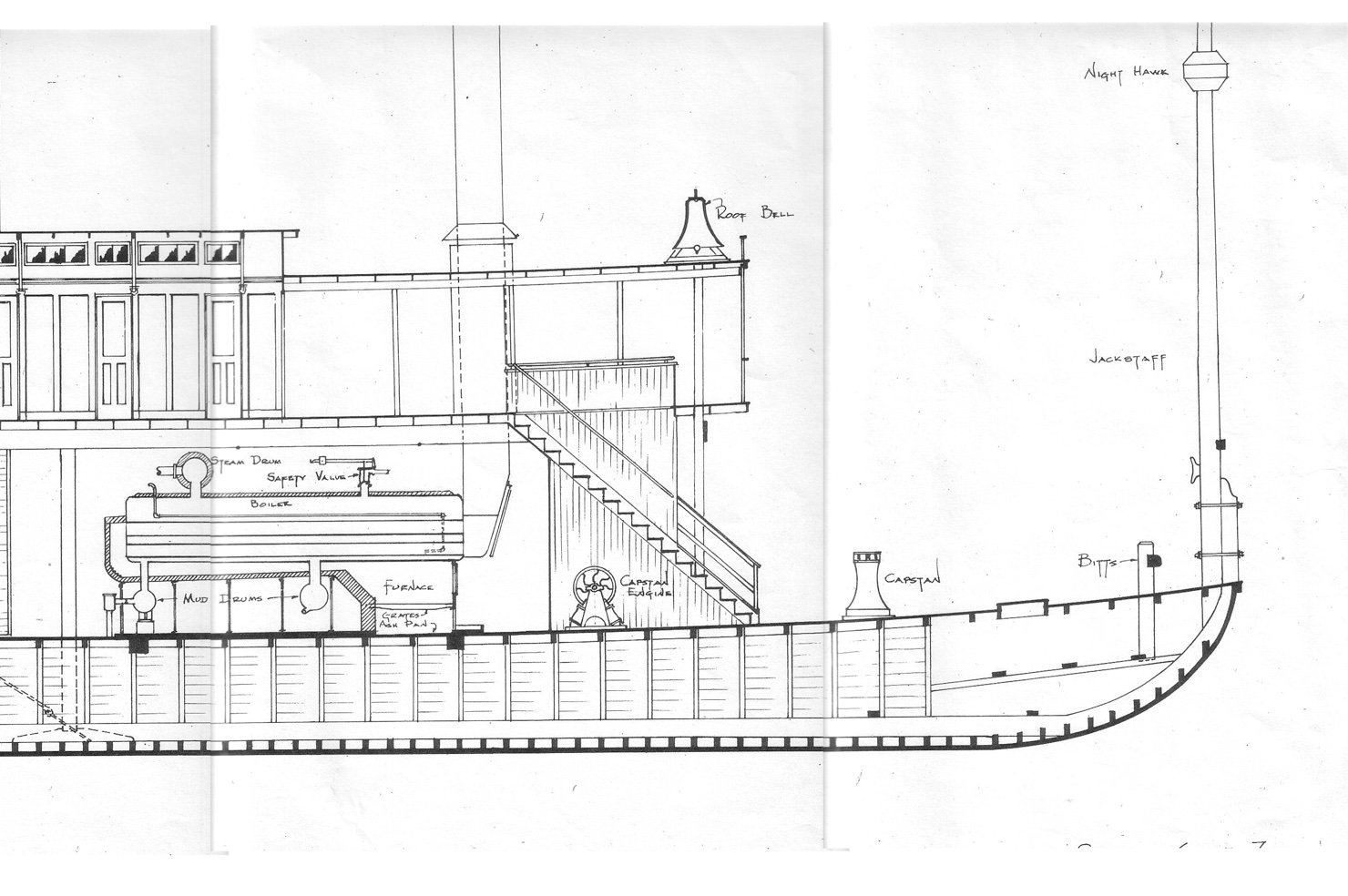
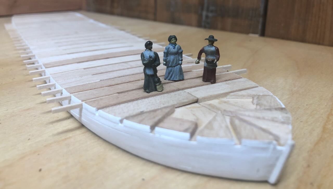
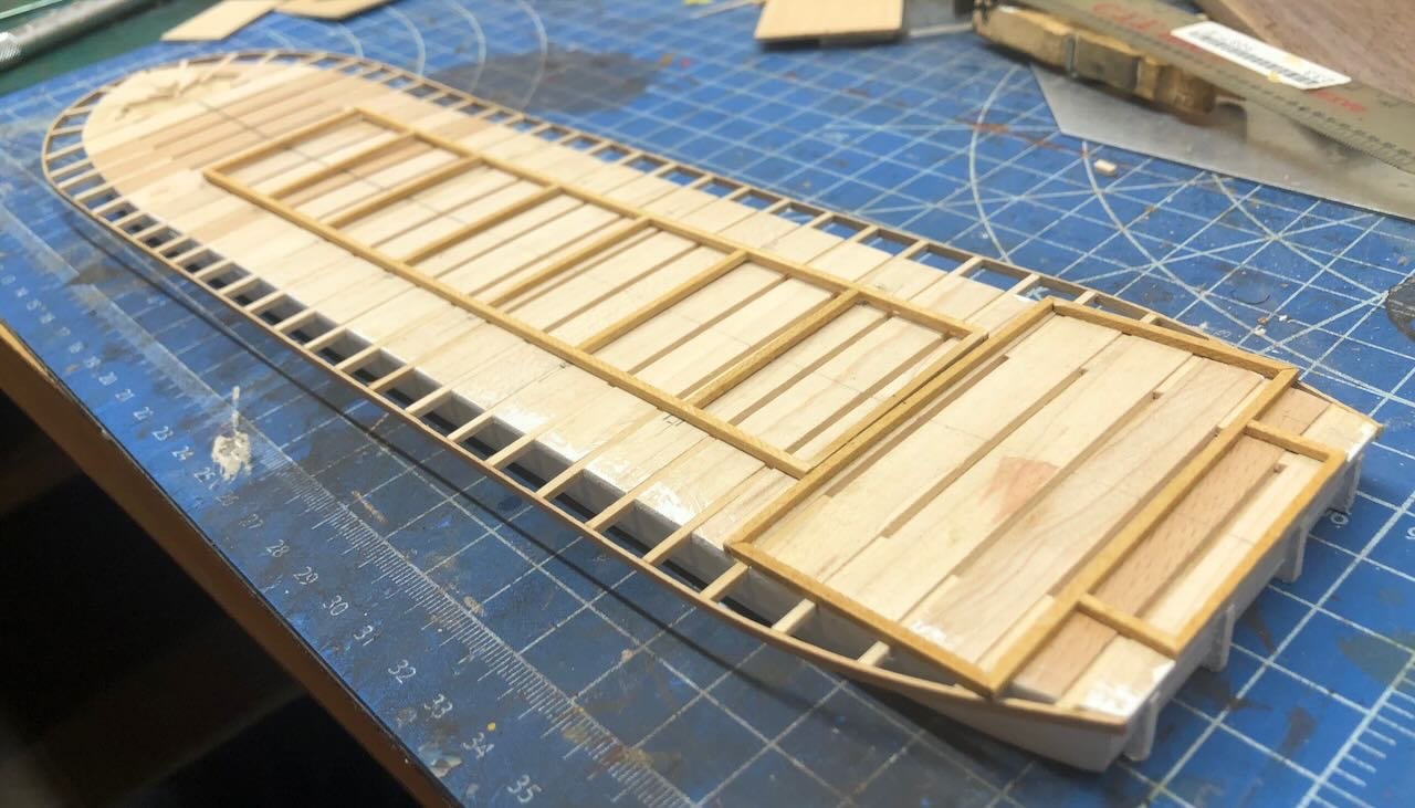
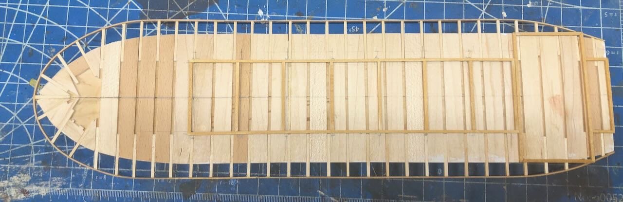
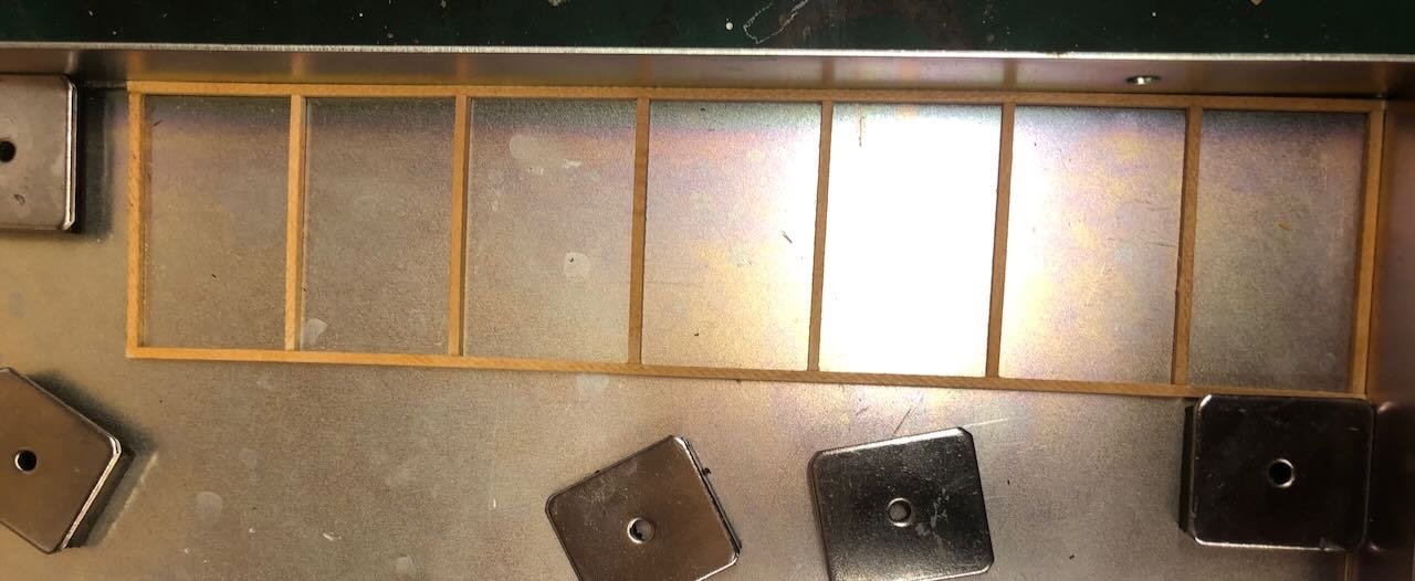
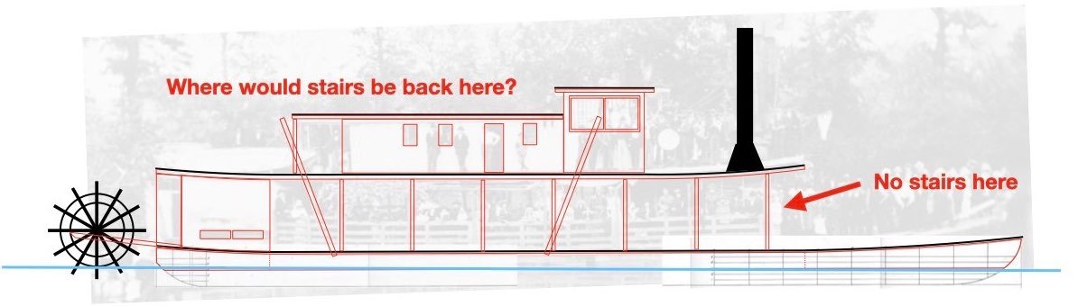
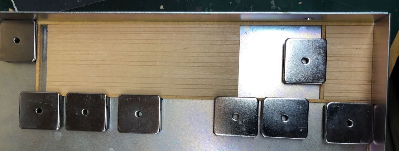
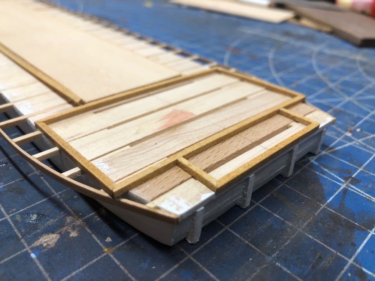
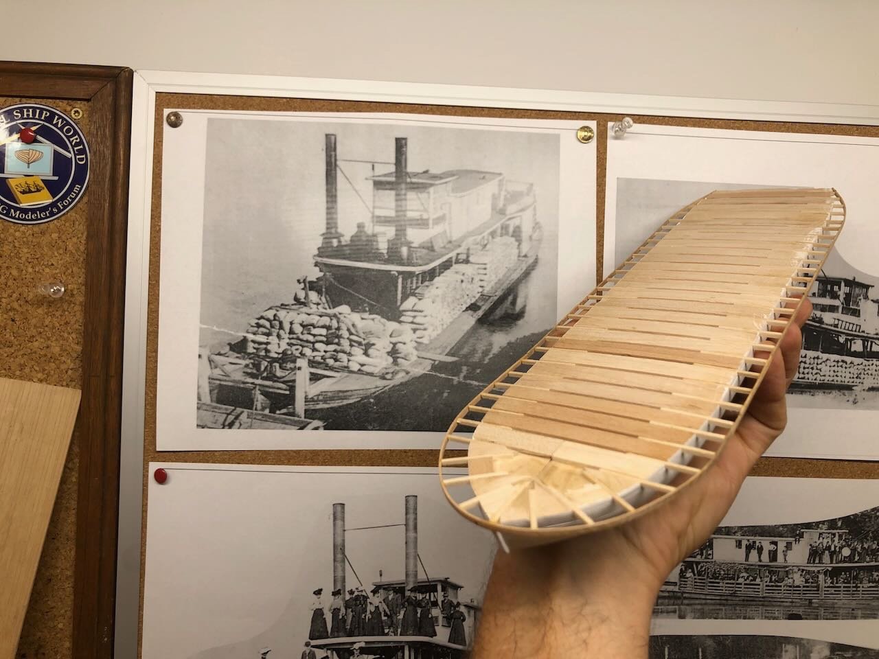
Here's the completed boiler deck framing, first in the magnetic square, then two shots resting on the main deck. I think the next step will be starting to lay the decking, for which I will be going back to homegrown wood, meaning I need to mill a whole bunch first. That means I probably won't make more progress until next weekend. But I do have a thinking-ahead question: Where were the stairs between the main and boiler decks on this vessel? Many steamboats placed them near the bow, in front of the boilers. But most of the main reference photos I'm using (see first post of this log) show no stairs there. A few photos do show stairs at the bow, but they appear to be a later retrofit, and aren't relevant to the earlier version I'm building. Here's a shot clearly showing no bow stairs: Here's a later shot (when she was operating down at Vicksburg and had clearly been altered) showing bow stairs: So where were the stairs in her Missouri River configuration? I've stared at all these photos over and over, and can't find any sign of a staircase. Anyone have insights into an alternate staircase location, based on actual practice in other vessels? There has to be a proper staircase, if nothing else because multiple photos clearly show crowds of ladies up on the boiler deck, and they sure didn't climb a ladder. And if it's not at the bow, it has to be much further back, because the boilers sit below the pilothouse and you couldn't put stairs there. That also forces passengers back into the engineering and cargo spaces, an odd choice; the value of bow stairs is that it kept passengers out of the crew's way. There's also no sign of stairs along the outer edges of the deck toward the stern, a location that would also keep the passengers out of the engine/cargo space. They almost have to be internal somewhere, but that seems really odd to me. Here's an annotated drawing laying out the question: Thoughts?
-
That's so great to hear! To me, one of the great joys of model building isn't assembling, but understanding. You've done a great job on this model, it'll be an excellent highlight wherever you choose to display it. As for next model suggestions, while I can't know what would give you joy, if it were me, I'd go with one of their cargo vessels (tanker, Liberty ship, etc.). Lots of people build warships but merchant vessels are far less well represented in the modeling world and are fascinating in their own right. And it'd be a fitting tribute to all the sailors who served on such vessels but get only a fraction of the recognition their more famous naval colleagues receive.
- 25 replies
-
- 3
-
-
- Harriet Lane
- Model Shipways
- (and 1 more)
-
Timber-framed outdoor kitchen - Cathead - 1:1 scale
Cathead replied to Cathead's topic in Non-ship/categorised builds
This manufacturer offers versions that are completely finished; they'll truck it right to your door. As long as you have a route that it can be hauled along (they're not light), you could have this on your back patio: A lot more expensive, but practical if the money is there. https://www.fornobravo.com/product-series/primavera-series-wood-ovens/ There are larger sizes, too, you can browse the site. We're stubborn and wanted to have some ownership of it, plus the lower cost was relevant to us. As for covering, as shown above, when finished properly they don't need to be under cover. But being out in the open also limits the conditions in which they can be used. In our case, building the kitchen structure allowed us to (a) worry less about getting a perfectly sealed finish on the homemade oven kit, (b) make use of it in far more variable weather conditions, and (c) integrate it into a broader kitchen setting with grill, smoker, sink, etc. This was important to us as we saw this as an important aspect of our self-reliant homestead life, not just a recreational highlight (not that there's anything wrong with that). I fully intend to use this when it's raining/snowing/boiling. I'm so sad for you! I have family roots in southern Mississippi (among other places). We adore okra; sauted, roasted, in stews, you name it. I will say that okra is one of those vegetables whose quality is highly dependent on freshness. Grocery store okra is trash. Fresh okra from the garden is a different story. Okra does NOT store or travel well, it needs to be fresh-picked and used. And preparing it well does matter. I have found numerous people who thought they didn't like okra until we prepared it for them. But I do admit there's no accounting for some folks...;) -
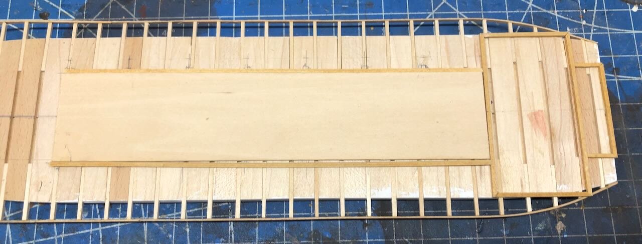
I've started laying out the forms for the superstructure. Peerless, like many similar vessels, has a very simple deck layout: a solid engine room structure at the stern and a series of posts going forward. So I laid out the shape of the stern structures pretty easily, after some careful measurement and decision-making: If you're wondering about the coloration in the middle of the forms...it's what you probably think it is. Like all the rest of my models, there's now a little bit of me in Peerless! After this I started laying out where the posts would go. To do this, I cut a rectangle from a thin sheet of scrap wood in the exact internal dimensions I wanted, and laid it on the subdeck to mark out where posts would go. At this point, I also decided I would build the frame that rests on top of these posts, essentially the subdeck for the boiler deck (if you're confused, on Western river steamboats, the boiler deck was the deck above the boilers. No one knows why). Building this now would help ensure that I could lay a nice square structure on top the posts, rather than having to build it in place later. So here I'm laying out and cutting the longitudinal beams for this, again using my sheet wood as a guide: And here I'm using my magnetic squaring jig to begin gluing up this sub-boiler-deck framing, again using the scrap sheet wood as a form (this will not be present in the finished model): Once I have this sub-structure built, I'll lay it over the sub-deck to double-check my post locations, then it's time to start laying decking, being sure to leave holes for the posts. Thanks for reading!
- 259 replies
-
- 10
-
-
Timber-framed outdoor kitchen - Cathead - 1:1 scale
Cathead replied to Cathead's topic in Non-ship/categorised builds
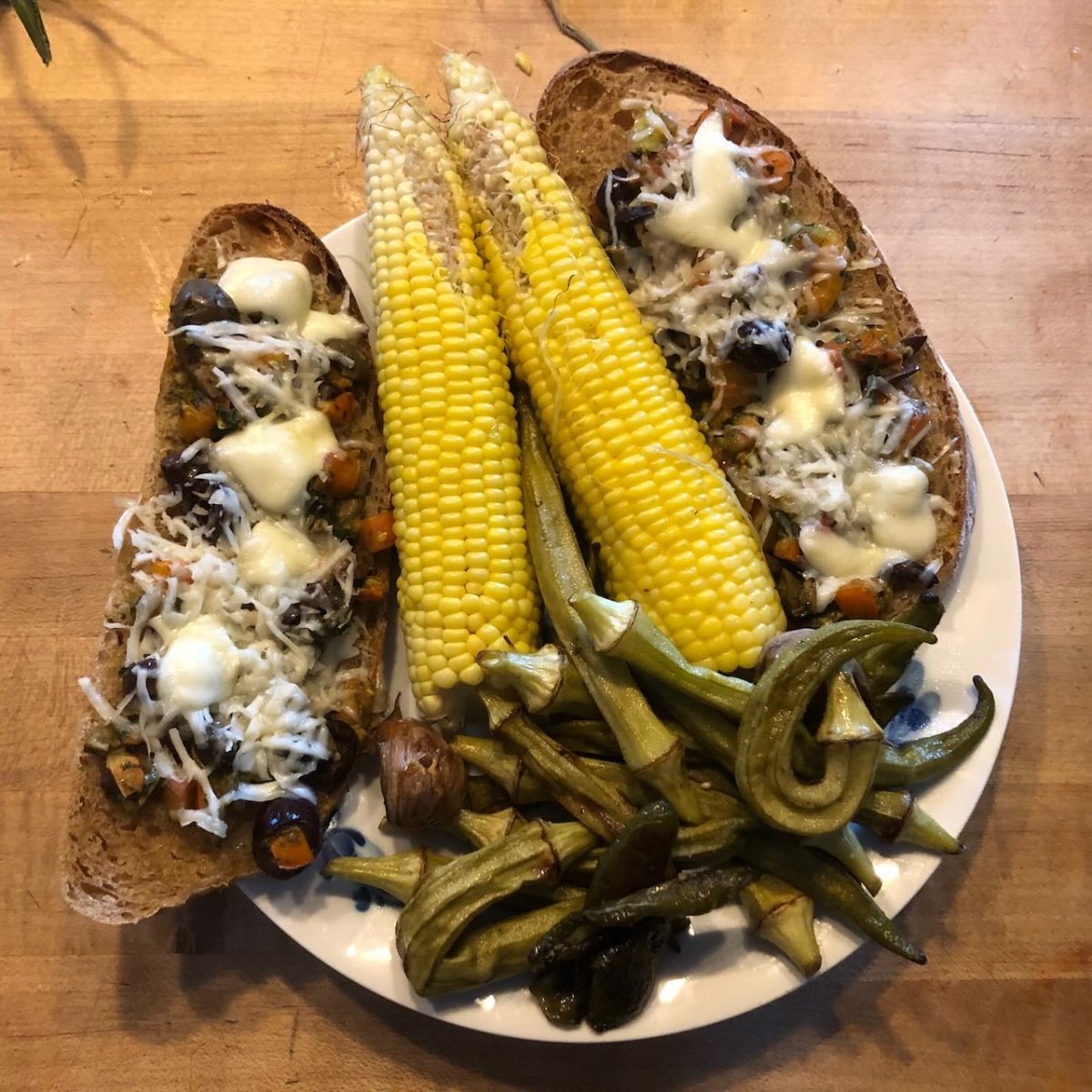
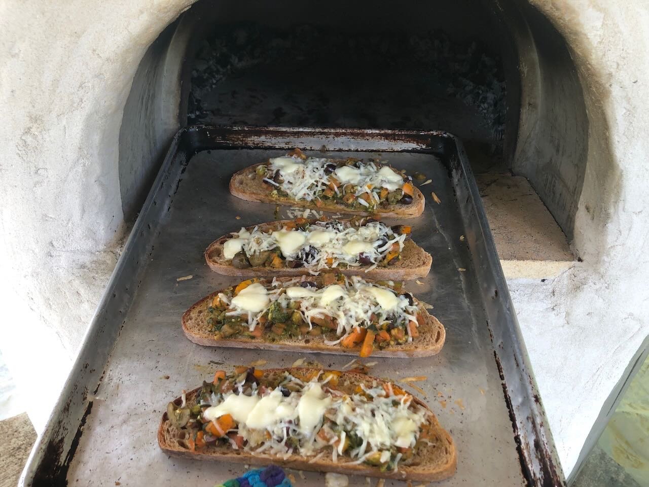
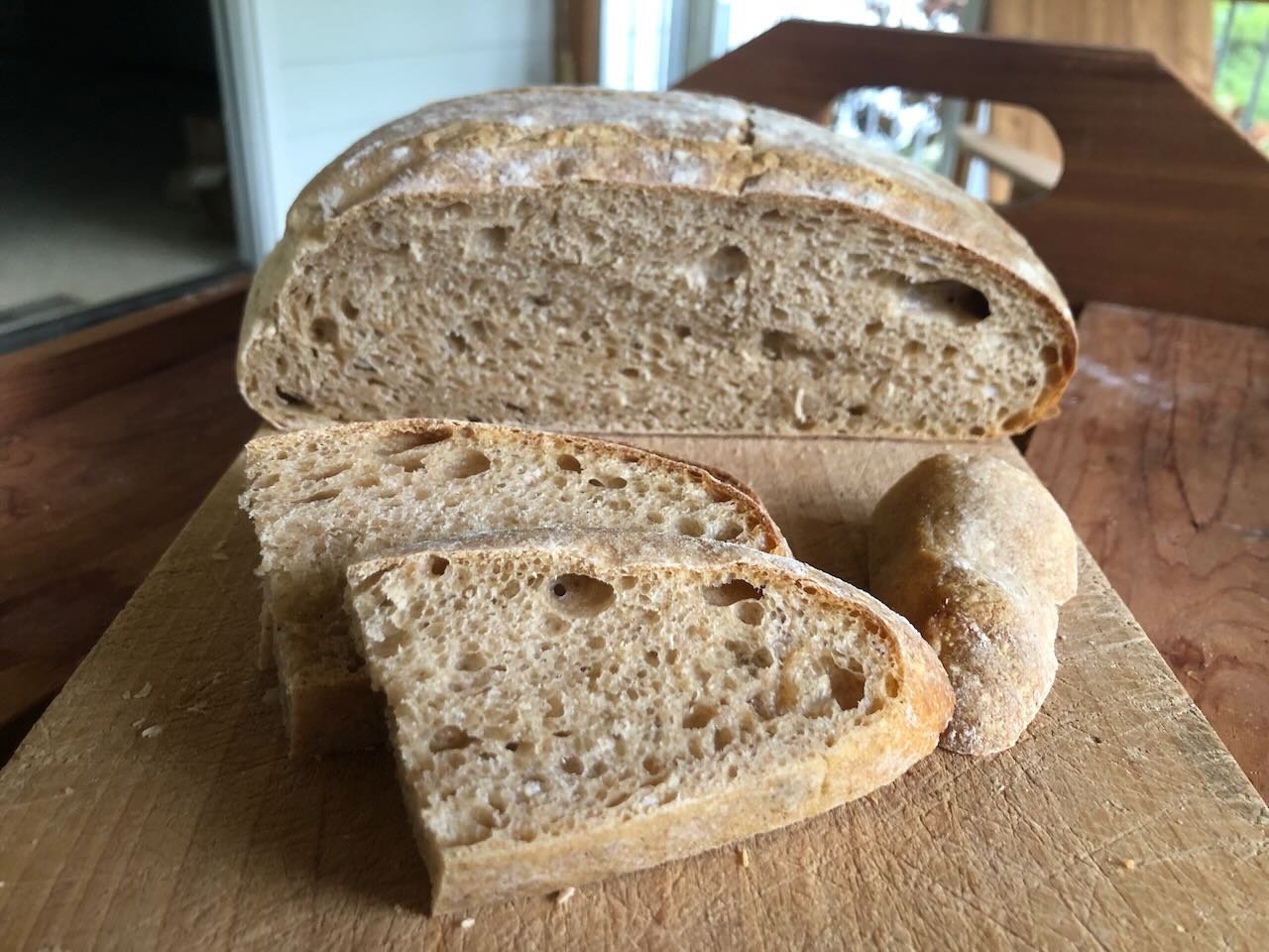
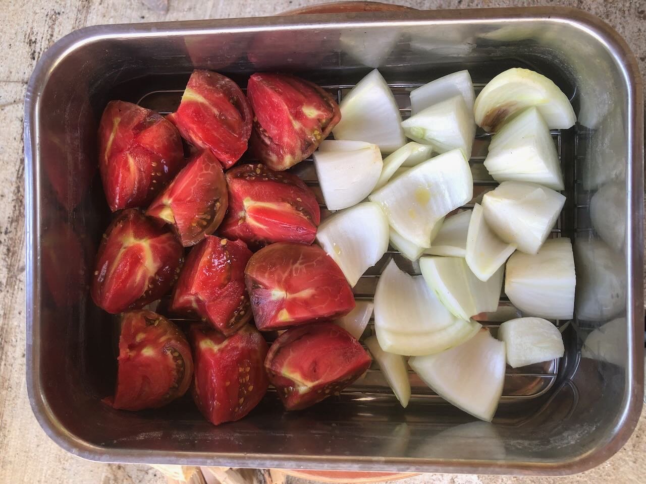
OK, another food post, but with a purpose. If it wasn't already clear, one of the core values of an oven like this isn't an occasional pizza party, but the ability to cook a lot of things over a period of time with a minimal input of energy. The ideal efficiency is to have a lot of things lined up that require different levels of heat, then progressively bake/roast them over time. For example, Saturday late afternoon we fired the oven up to pizza temperature as some friends came over. We made a whole bunch of pizzas, then as the oven started to cool, put in two loaves of bread, then when those came out slow-roasted a large stack of fresh-harvested sweet corn. Many hours of cooking from the initial small armload of wood. Sunday midday we fired the oven again, roasted another large pile of sweet corn, then a pan of okra (roasted okra is food for the gods), then made a tray of bruschetta from yesterday's oven bread and lots of fresh-chopped garden veggies. Those all became lunch, after which we put in a large baking pan with two venison shoulders over a base of tomatoes, onions, garlic, & potatoes (all fresh garden produce). That slow-roasted all the way to dinner, making for another easy meal, while being followed by a tray of sweet potatoes slow-baking at lower temperature that we'll pull out around dark. All of that from the one initial midday firing with a small load of wood. Essentially no management work for either day of cooking other than the food prep. No 6-8 hours of heat being pumped into the kitchen by a standard range, costing us electricity directly and indirectly (through the need for extra A/C). Far higher quality; it's amazing how the truly even heat in this oven improves the cooking and flavor of everything we put in it. We got a lot of other things done both days because the oven takes care of itself. And we have food for days now. About 3 lb of venison leftovers, a whole loaf of bread (already ate the first one), leftover pizza, lots of cooked sweet potatoes and sweet corn, etc. This weekend really demonstrated a core goal for this project, the ability to produce a wide variety of high-quality food with a small input of on-farm firewood, no electricity or wasted in-house heat, and minimal kitchen fuss. Next up I'll be working on the open firebrick grill that will sit next to the oven, allowing us to do other large-scale cooking projects like boiling down tomatoes for canning, reducing maple sap to syrup, and of course normal grilling of homemade venison sausages, burgers, and all sorts of other stuff. Another loaf of brick-oven bread: Bruschetta: Lunch of bruschetta, roasted okra, and roasted sweet corn, all from the oven: Roasting pan of 4.5 lbs of venison shoulders, lined with garden tomatoes, onions, garlic, and potatoes, after ~4 hours. Meat falling off the bone tender: It is indescribably sweet to be reaping the dividends from a project that took way longer, and far more effort, than we initially (naively?) thought, and one we dreamed about and discussed for many years. Thanks for your tolerance and interest, stay tuned as I keep adding features to the kitchen overall.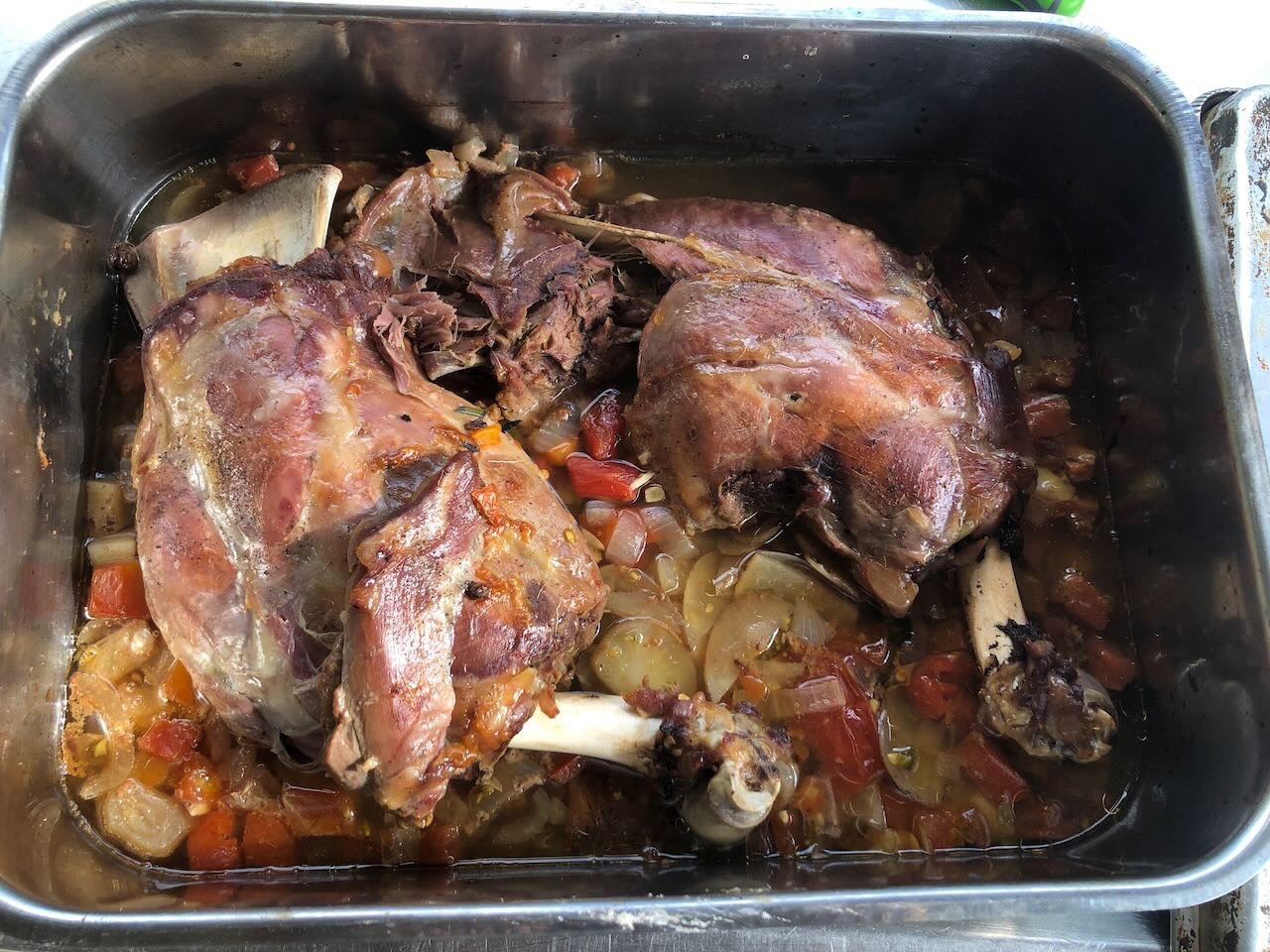

- 131 replies
-
- 11
-

-
-
Are they oar loops? Were these vessels rowed? They look exactly like the rope loops used for primitive oarlocks on vessels like Lewis & Clark's keelboat.
-
Timber-framed outdoor kitchen - Cathead - 1:1 scale
Cathead replied to Cathead's topic in Non-ship/categorised builds
I could send/take you to some amazing railfanning around Kansas City. Can all but guarantee traffic every 15 minutes or so, often 2-3 at a time. -
Timber-framed outdoor kitchen - Cathead - 1:1 scale
Cathead replied to Cathead's topic in Non-ship/categorised builds
Oh, Ken, you were only a couple hours away! If/when I start my model railroad I may especially need to lure you over here, long drive from WNC be darned. -
Timber-framed outdoor kitchen - Cathead - 1:1 scale
Cathead replied to Cathead's topic in Non-ship/categorised builds
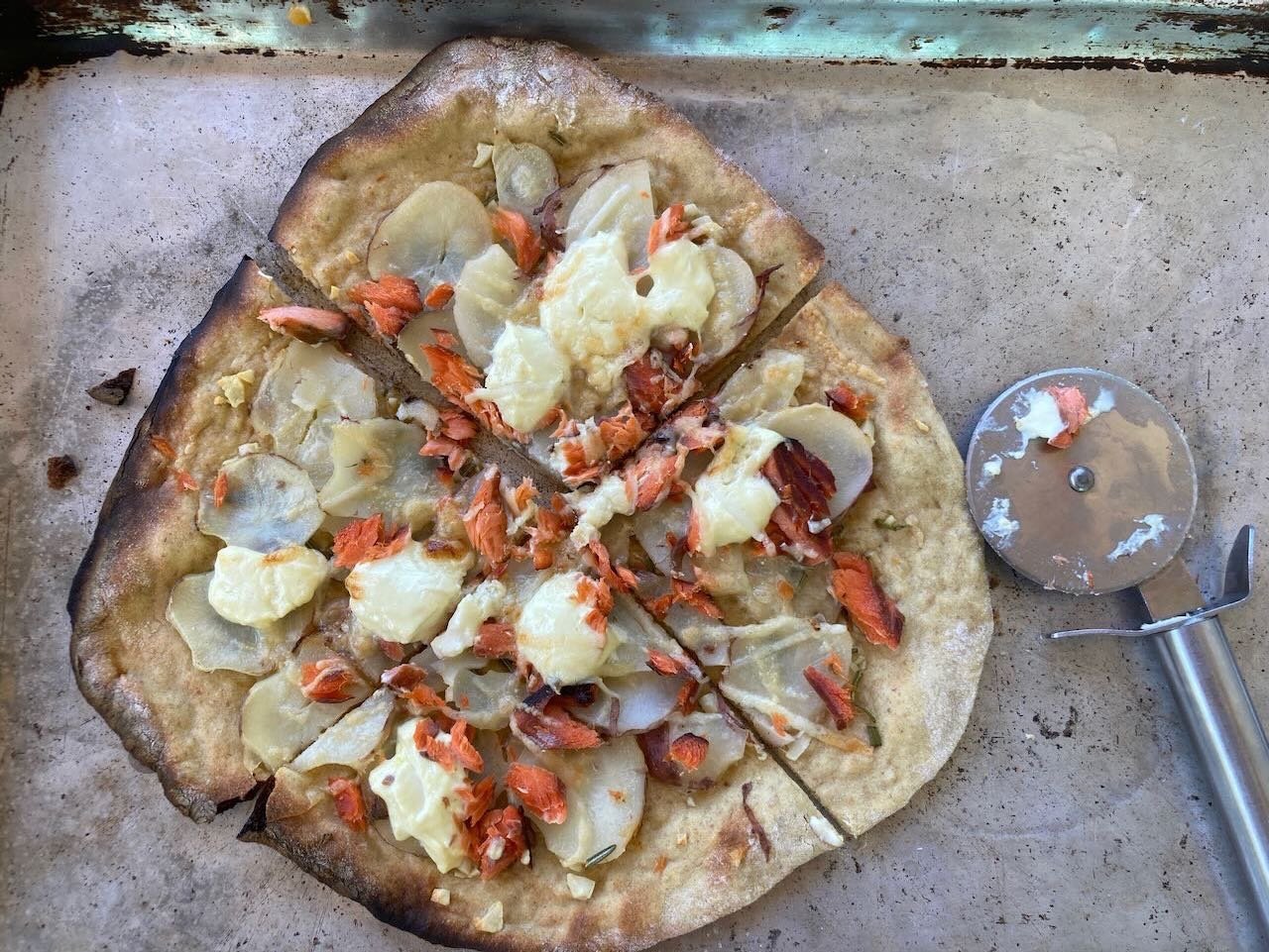
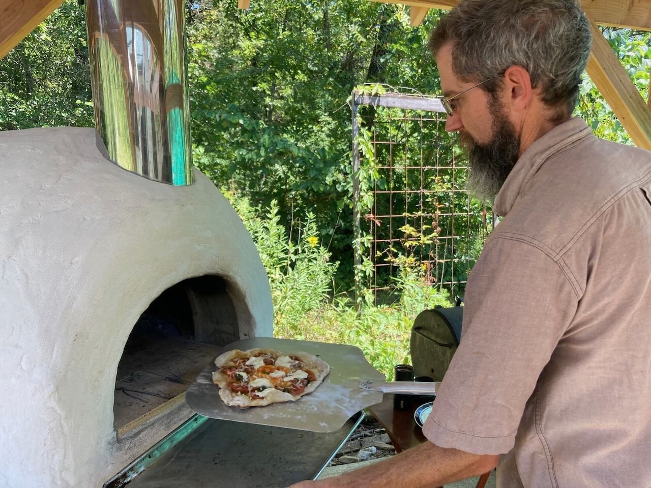
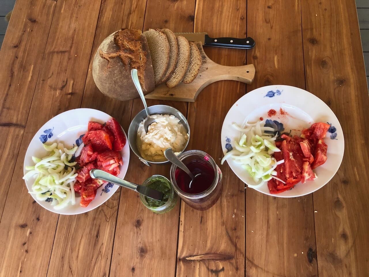
So we've been cooking and baking all week as we raise the temperature every day. Here's the first-ever loaf of sourdough bread, which made a nice simple lunch with sweet onions, cucumbers, tomatoes, basil pesto, and pickled beets (all from the garden) as well as homemade ricotta cheese (milk from a local dairy). But today we reached the pinnacle. 10 months after physically starting the project (not counting far more planning, much less the lead time for logging and milling the lumber), we made the first pizza! Here's a nice gif I made of a fire blazing in the oven as it heats: As the oven heated, I pre-roasted a pan of garden tomatoes and onions (shown here pre-oven): And we assembled many more garden-fresh toppings. Apologies for the color balance on these, we had a green shade cloth hung on the south side of the kitchen building and it was altering the light rather strongly for closeups. Here I'm inserting a pizza: If the crust looks a little lumpy, it's because I (embarrassingly) messed up the dough, making it too wet. I've been making dough consistently for years, but I guess I got distracted with the excitement and it was sticky and hard to work with. The one shown below got a little scorched as we got used to timing, but garden potatoes & garlic with home-smoked salmon is a pretty good combination: I promise I won't turn this thread into a long-term food blog, but since the purpose of this entire project is to produce good food, I feel justified in sharing some of the initial outcomes. It's also worth showing just how flexible this sort of oven can be. And to repeat myself, it was absolutely wonderful to not have an electric oven drawing power and blazing 550º into the house on a summer's day. Much nicer to sit in a chair in the shade of the outdoor kitchen while a few pieces of wood do their magic. We enjoyed a whole pile of pizzas while finishing off a bottle of homemade wild grape mead. Also made more bread: Now that the oven is in service, the next project is to build the wood-fired grill in the space next to it. Not quite sure when I'll get to that, but I'm hoping in the next few weeks. I'll probably also share a few more food stories as we experiment with other things.

.jpeg.e70aa9c8b1c95c74b7d1450edcbca97a.jpeg)
- 131 replies
-
- 13
-
-
-
That's a cool jig, I may copy that! I've also used the "hunt for a household item with the right curve" approach, many times. Great progress. It's frustrating when instructions are wrong, hope the fix goes smoothly.
-
I agree with Kurt, I bet you'd be surprised how many modelers would enjoy seeing your work in person. Photos never do models justice, or at least they're not the same experience as real viewing. Entering a contest doesn't have to be about being competitive, you can just think of it as a framework for sharing work in person. And I'm so glad you chose to share this build with us. Such a unique prototype; I really enjoyed learning about it and seeing the project unfold. This is also the kind of model that may well find a home beyond yours one day; unlike the thousands of, say, Constitutions out there, it's special and would probably have value to a library or local museum when you're ready to part with it. "Museum-quality" is an over-used term in model ship building as it tends to have a condescending tone that implies anything below Smithsonian-level is unworthy, but museums come in all sizes and serve many constituencies. Models are almost always a crowd-pleaser in any setting and I've seen far lower-quality models than yours proudly displayed in local museums and enjoyed by visitors of all ages. By all means enjoy it in your home, as I currently do mine, but one beauty of building unusual and region-specific models is the higher potential for them to live beyond us. Thanks again for your work!
-
The next step was to wrap these guard beams with an outer strip of wood; I have no idea (or have forgotten) what this was called in practice (anyone know?). It's functionally like the wales on a regular sailing ship, though it's not part of the hull. For these, I transitioned back to my own homegrown wood. I carefully milled some thin strips of maple whose width roughly matched the average thickness of the guard beams. One of these I soaked for a while, then carefully bent it around the entire bow, clamping it in place and using an electric plank bender to apply heat to the curve. Having not used this tool in a while, I carelessly applied heat to a finger as well, requiring another local plant-material harvest, this time a piece of aloe. Once I was happy with the curve, I applied beads of glue to the end of each beam, then thoroughly clamped the bow curve in place. Once this had hardened, doing the two sides was quite easy, just more beads of glue and more clamps. It was entirely a fortuitous coincidence that the width of the guards was just about the same as the depth on these clamps, though I ended up placing another thin strip outboard of the glued strip just to ensure that the clamps fully held the "wales" onto their beams without the clamps nudging up against the hull and leaving a slight gap. It would have been really smart to think about that and make the guards slightly longer! I didn't photograph this step, but here's the finished result: I'm really pleased with this. The maple is obviously harder and smoother than soft basswood, and takes a curve with no flaking or cracking. It's starting to look like something. For fun, I held the hull at this stage up to two reference photos, so you can judge for yourself how it recreates the lines of the original. The next step is complicated. My plan is to lay the decking, which will rest on the "wales" and be sanded smooth to match that curve. I'll then lay a second layer of "wales" around the outside of that, wide enough to cover the lower layer and the planking, essentially sealing it all in. But I have two ways to proceed in the long run. One is to lay the decking first, then lay out the superstructure and just built it on top of the decking. The other is to lay out the superstructure now, and build some guides or markers into the decking before doing the planking. I dabbled in this second way when building my Arabia, as shown in the photo below, where you can see how I laid strips a bit thicker than the decking to guide later placement of the aft superstructure and wheelhouses: Here's another view with the deck completed: My recollection is that I found these guides pretty useful, and am leaning toward doing this again. It also has the benefit that I can mark up the current sub-deck surface with pencil all I want, rather than trying not to mark up the nice maple deck I plan to lay. I'm also leaning toward doing something I didn't do on Arabia, which is to lay out where all the forward support posts go as well, and potentially planking around them so they sit in a slight recess into the decking rather than sitting on top. This would be a lot fussier but I think would look better and be a bit stronger. It would also help solve the problem I noted earlier, in which not fully filling the guard beam slots means that some deck posts might be left hanging over an empty slot. Laying them out first would mean I can fill a slot with scrap wood if needed, to support a given post. Thoughts/input welcome. Thanks for reading, liking, and commenting!
- 259 replies
-
- 18
-
-
-
I agree, Roger, it's something that's always drawn me more to these working boats than the big showy ones. A fun twist on this for Peerless is that she was built the same year the MK&T railroad began building its line down the Missouri River. Until then transportation for communities on the northern side of the river was still river-based, as roads were few and the terrain was pretty rugged. It's possible that she helped carry supplies for the railroad crews upriver, contributing to the very project that would eventually undermine her economic viability. Not to mention, road bridges were especially rare over a river as big as the Missouri. The MK&T bridge at nearby Boonville was one of the first built over the lower Missouri, and a road bridge didn't come along until much later. Without ferries or other steamers, the opposite side of the river might as well have been the moon. Even today you have to drive a long way between road bridges over the Missouri. And like the Ohio River, much of the terrain along the lower Missouri was/is quite rugged, making river travel essential. Railroads were very late to penetrate the especially rugged Ozark terrain south of the Missouri, making steamers like Peerless last in service much longer than in more accessible areas.
-
Looks good so far! Great choice of prototype.
-
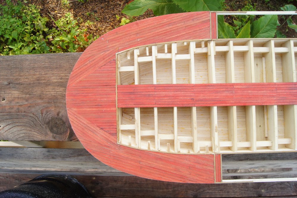
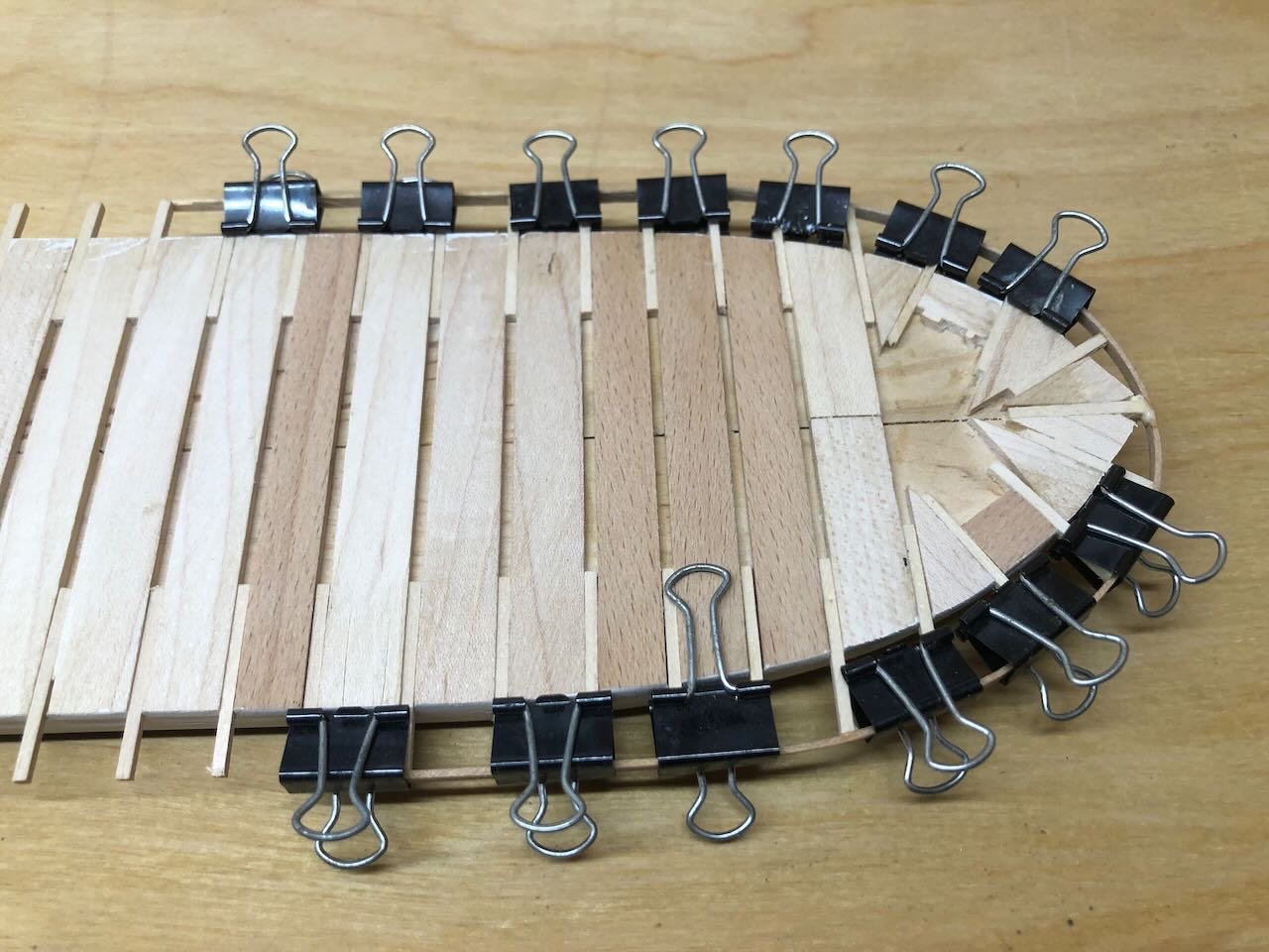
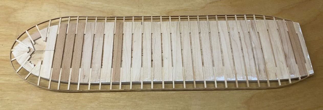
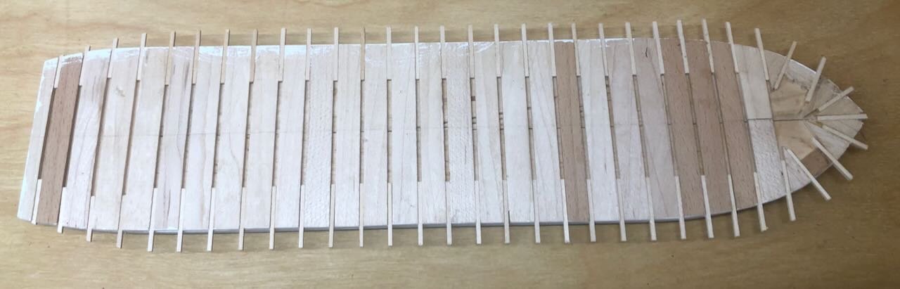
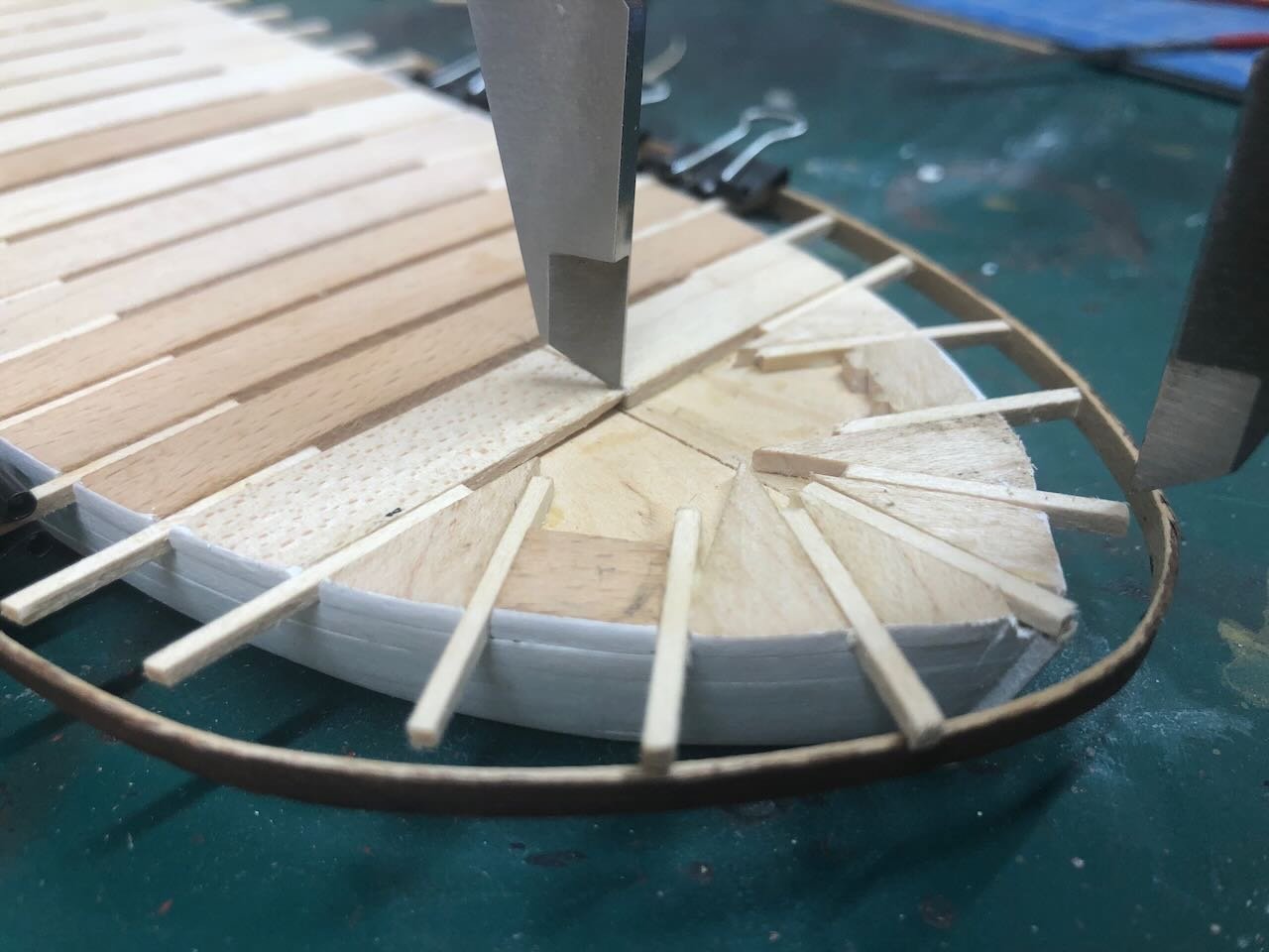
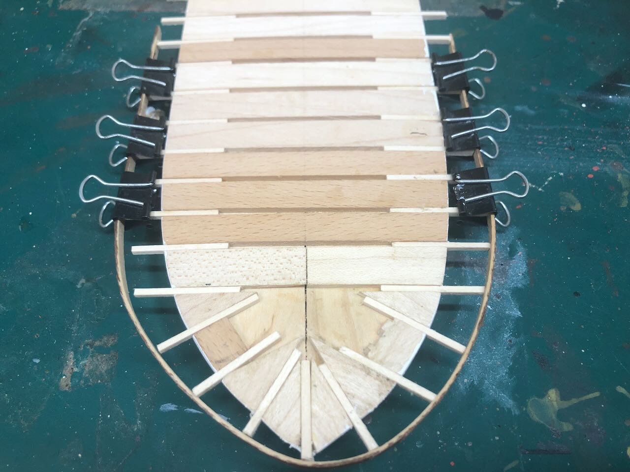
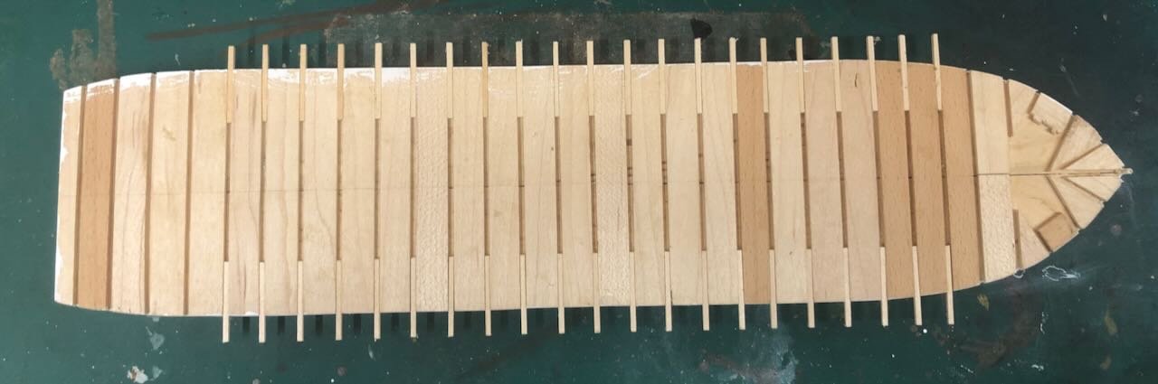
And the guard beams are finished! To form the curve at the bow, I soaked and clamped a flexible piece of wood into the approximate curve I wanted, and used it as a guide. As you can see, it didn't bend evenly, so I focused on the port side (right in the view above) as the curve there was smoother. Above, all the beams are just being test-fit. I installed the guides the way I wanted on the port side, then used calipers to transfer the same measurement for the length of the starboard side. Once the glue was dry, I did more test-fitting with the wooden strip and did some sanding and shaping of the beams to ensure they'd hold the curve I wanted. I used the same procedure at the stern, which was much easier. So here are the completed bow, stern, and full hull.
- 259 replies
-
- 19
-
-
Timber-framed outdoor kitchen - Cathead - 1:1 scale
Cathead replied to Cathead's topic in Non-ship/categorised builds
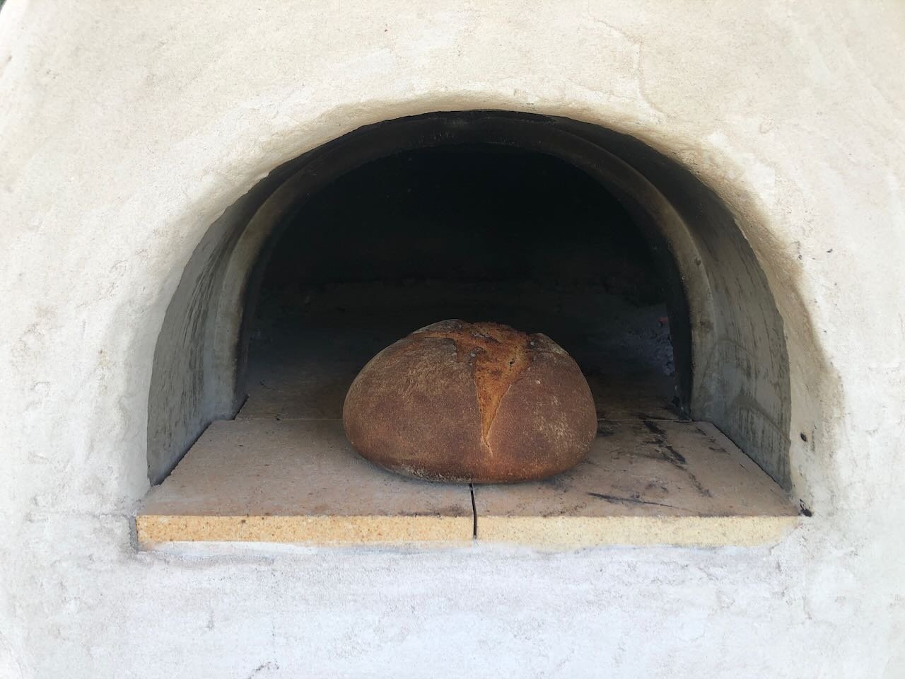
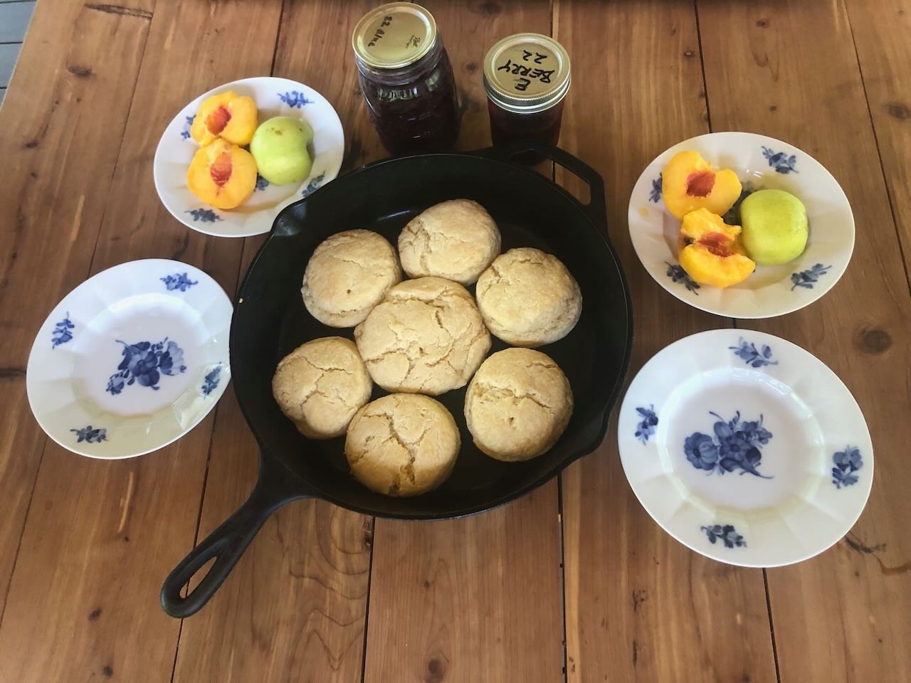
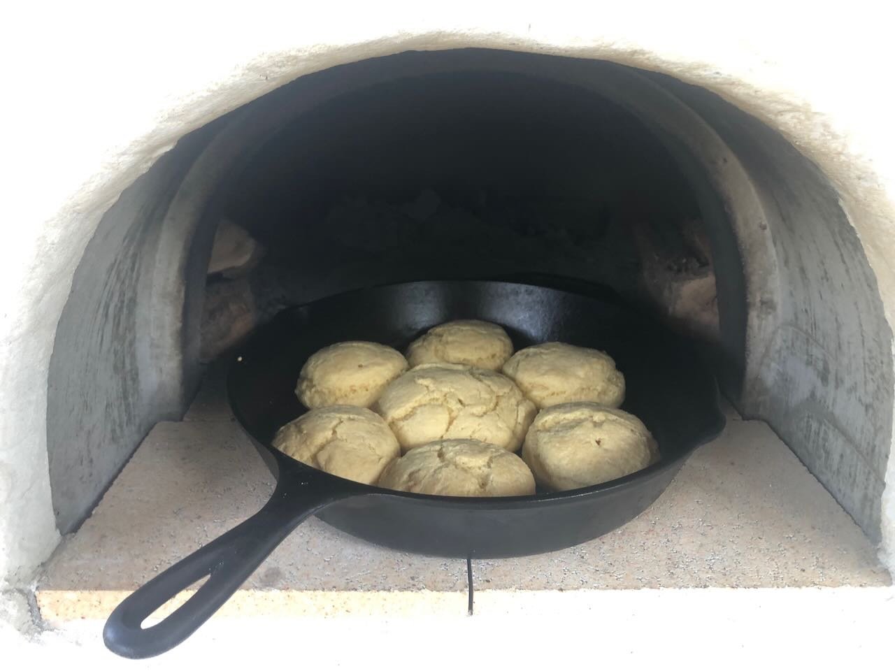
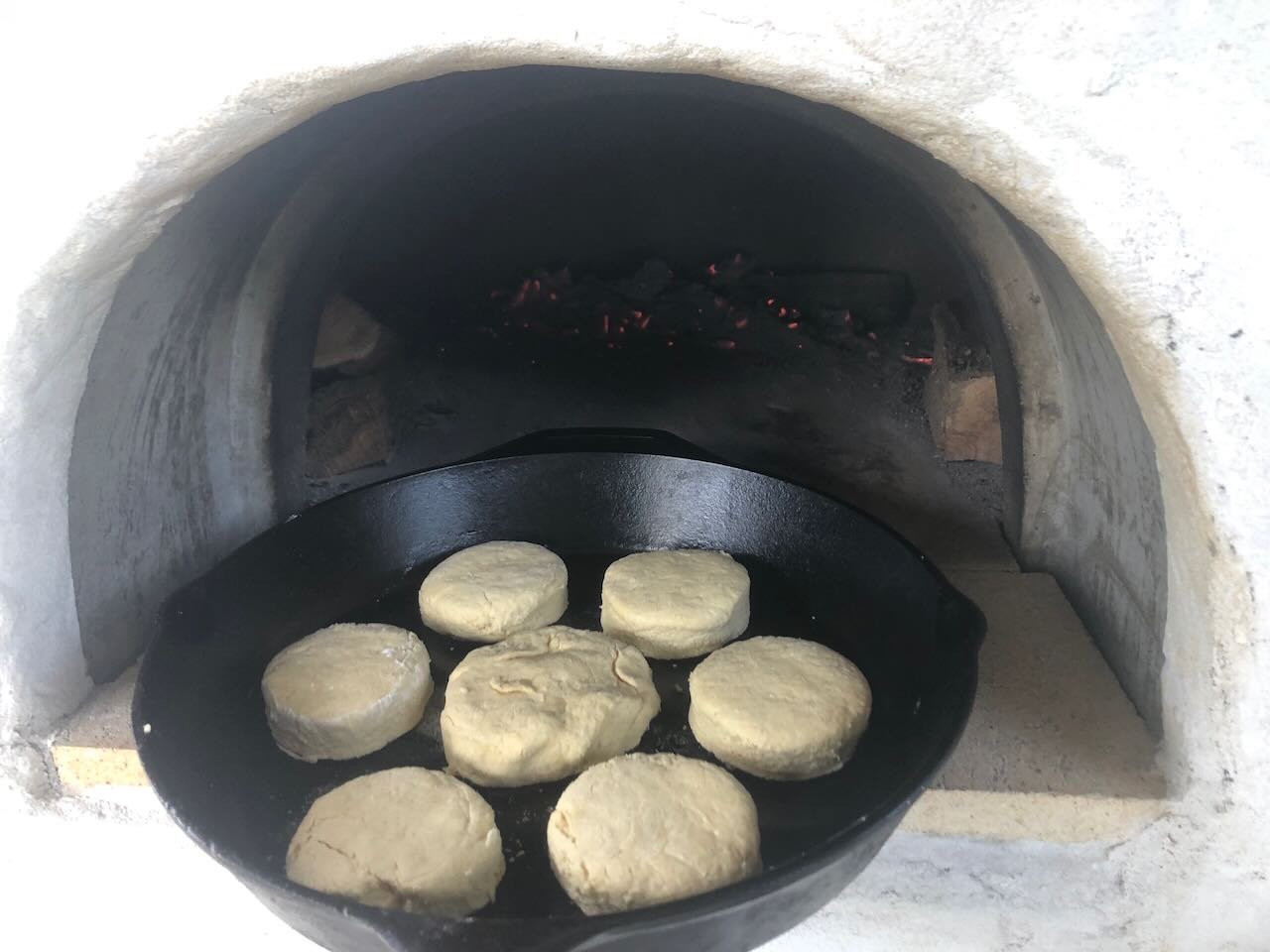
With each day, we raise the temperature in the oven a bit. 300...350...400...450...by the end of the weekend we should be up in the 700 range and ready for pizza. We're taking turns working outdoors (the joys of being work-from-home "laptop class"), while keep the fire gently fed. We fire it every morning, work outdoors until midday, then close it up until evening, when we fire it again. It's already holding heat nicely; even after being left alone overnight it's still reading an internal temperature of 200-300 the next morning. This is and will be our hottest week of the summer, and indeed probably the hottest week we've had since 2012, with daytime temperatures over 100 and heat indices closer to 110. But the shade of the kitchen structure does wonders, and that's why we're taking turns! The best part about it starting to hold heat properly is that it's now stable at temperatures suitable for normal cooking, if not yet proper pizza. So this morning we inaugurated the oven with a batch of homemade biscuits, shown below going in and coming out, baked at a nice comfortable 400-450. If you're wondering about the wood off to either side in the oven, we're stacking a few pieces at a time in there to super-dry from the oven's heat. This makes them burn all the better, and indeed is the long-term cycle: once you're finished a round of cooking, you stuff the cooling but still-warm oven with firewood to kiln-dry for the next time. And here's the first meal based from the oven: biscuits with homemade elderberry and blueberry jams, fresh local peaches, and fresh apples from our orchard. And no oven run in the house to counteract the A/C during this scorching week! Tomorrow the oven will be hot enough to bake an inaugural loaf of bread. It's so exciting to finally be producing food from this year-long project!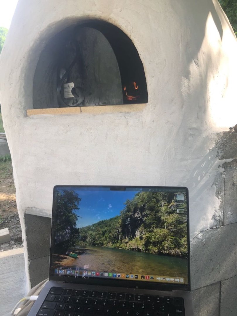
- 131 replies
-
- 12
-
-
-
Timber-framed outdoor kitchen - Cathead - 1:1 scale
Cathead replied to Cathead's topic in Non-ship/categorised builds
Sorry, Keith, I don't. Can ask him when he returns in fall. He's on Facebook, if you have access to that (I don't) you might be able to learn more. https://www.facebook.com/BristolBayNerka/ -
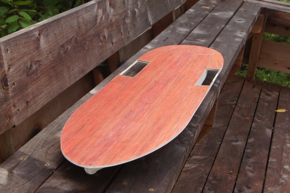
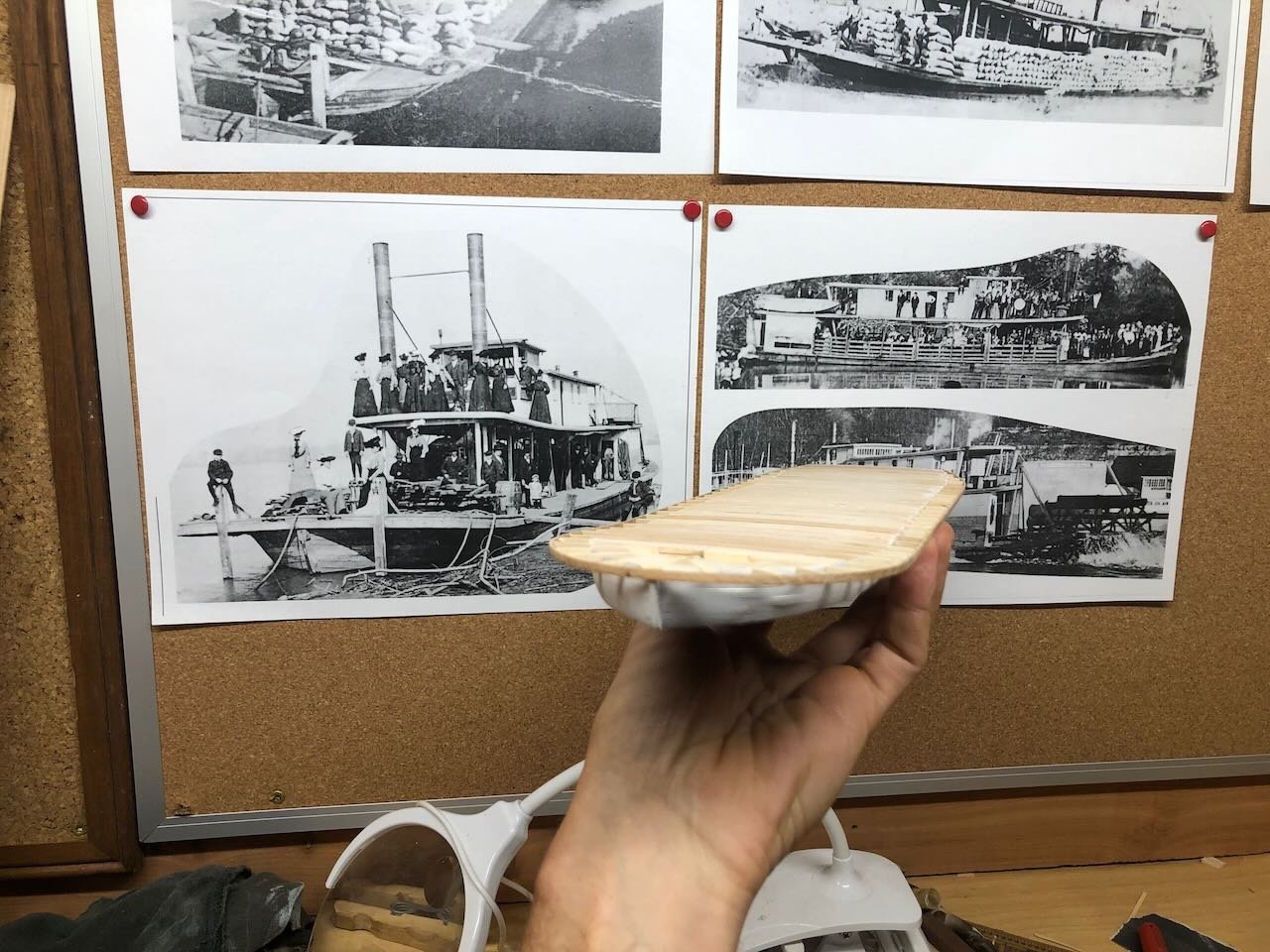
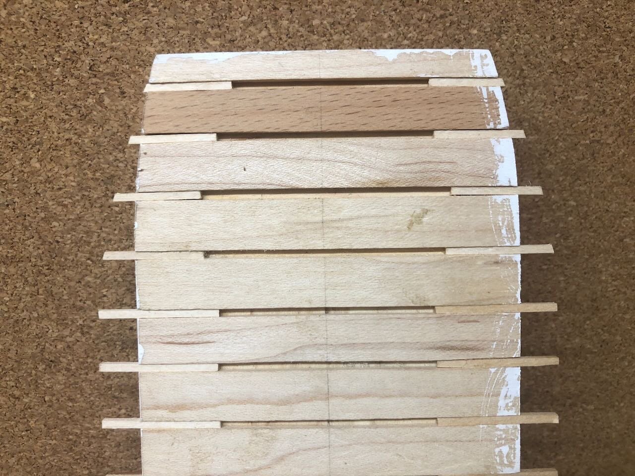
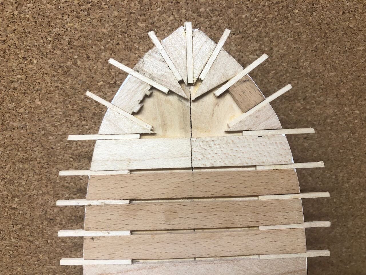
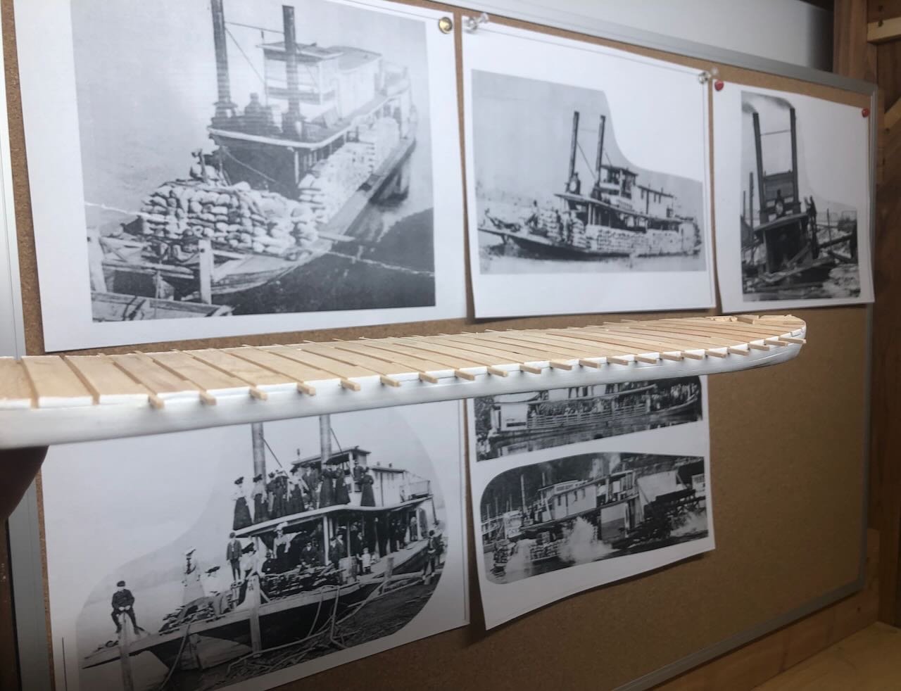
OK, wisdom of the crowd wins. I went ahead and cut/glued most of the guard beams as short segments, doing all those that form a straight edge. To fore and aft, their length will change to support curves at bow and stern, so I'll do those once these dry so they form a solid base for forming the curve. If this doesn't end up being the right decision, it's now all your fault! You might notice that, at the bow, I kept the line straight beyond where the hull starts to bend inward. That's because the shape of the deck should form a rounder curve into the bow, not a sharp point as in the hull. This creates an especially broad overhang on either forward quarter, which you can see especially well in the photo below. I also finally got around to printing out some of my favorite reference photos and pinning them to the tack boards above my new workspace. So here's the current hull with its inspiration. Another evening this week, I should be able to finish the rest of these beams. Thanks for reading, liking, and commenting!
- 259 replies
-
- 14
-
-
I found, when rigging, that it added quite a bit of enjoyment to work at understanding how rigging actually worked in general, so that I understood what I was setting up and just not assembling a mess of lines. Doing so also helped me catch what I felt were a few errors in rigging plans, and make changes that made sense to me in terms of how the lines would actually function.
- 25 replies
-
- 1
-
-
- Harriet Lane
- Model Shipways
- (and 1 more)