Check out our new MSW Sponsor Innocraftsman
×


jbshan
-
Posts
1,222 -
Joined
-
Last visited
Content Type
Profiles
Forums
Gallery
Events
Everything posted by jbshan
-

Simulated caulking
jbshan replied to Nirvana's topic in Painting, finishing and weathering products and techniques
Brian/Gunther, you got it. The soft pencil leaves enough graphite and doesn't crush the edge. The glue 'sets' it so it doesn't bleed or come off with scraping or sanding. It is subtle enough in smaller scales and a bit uneven which looks good to my eye. You really don't want stark black lines or you risk it looking cartoon-like. I've only tried it on decks so far though I could have used it on my 1:24 Philadelphia hull perhaps. I used paper between the deck planks there. Quite a bit larger than the 1:64 I'd done before. -
Gunports
jbshan replied to piperck's topic in Building, Framing, Planking and plating a ships hull and deck
That sort of port cover would be called 'half lids'. Constitution has those. It would be entirely appropriate to show those open. The hole is to allow the barrel to come through and make more room inboard. I had pictured, from the original description, something like these, on the quarterdeck.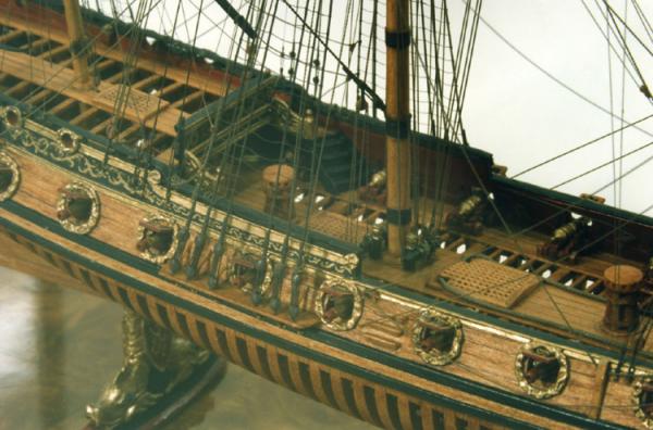
-
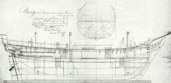
It's not quite the original plan, but just Google HMS Bounty plans, look for images, and several come up. This one was close, and much clearer than the plan shown from the NMM. There's also a book (McKay?) that will really help. It's in the Anatomy of a Ship series.
-
Gunports
jbshan replied to piperck's topic in Building, Framing, Planking and plating a ships hull and deck
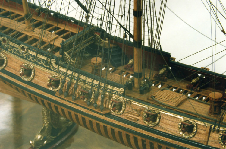
Until recently I would have fainted if somebody modified their aircraft carrier model to include side paddle wheels, but now, I have to wonder at the ingenuity of the Bureau of Construction. In the 1600s time frame upper deck ports were sometimes round, not much bigger than the muzzles, and with a wreath around them. If you decide to change them to Trafalgar-style ports, you could also paint the ship purple and add a flux capacitor. If you have information that the ports were at some time modified to a modern version, simply date your model to that time frame, but do all the changes indicated, not just those convenient, to be accurate. Constitution has had many changes over the centuries, some making her practically unrecognizable, but I think it behooves us to do all the changes indicated for each version, as a historical record. N. B.: they removed the flux capacitor in the 1927 re-working. -
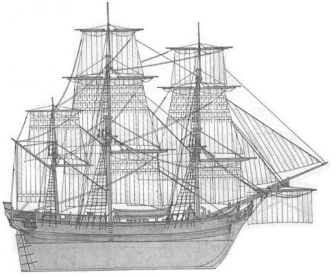
In general, the foremast, main mast and mizzen were raked in a splayed manner. The fore was raked either forward or vertical, the main a bit aft of that and the mizzen aft of the main. This changed over time. Later ships had less difference. Check the angles very carefully as the 'look' of the model is dependent on the rake of the masts.
-
Gunports
jbshan replied to piperck's topic in Building, Framing, Planking and plating a ships hull and deck
On your grand dad's Buick there are round vents on the front fenders. On your hot rod there are louvered vents. Do you feel those are interchangeable? -
Gunpowder Kegs
jbshan replied to DocBlake's topic in Discussion for a Ship's Deck Furniture, Guns, boats and other Fittings
I'm not sure if your model is of the specific time frame, but the gunpowder was changed around this time, to a more potent concoction. The new powder was put into marked containers so they wouldn't blow up the guns using the same amount of the more powerful powder. How this was marked escapes my memory at the moment. -
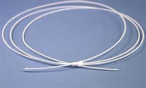
Starch or paint over a form or shaped by hand comes to mind. Milliners use a wire edging they bend to shape and the fabric holds the shape. Here's the wire, note it is wrapped with thread. Here is a hat. I suspect the petal shapes have wire in their edges as the fabric is too sheer for starch and not stiff enough to hold on its own.

-
Some very well-regarded paintings have changed over the years, Van Gogh comes to mind, Sunflowers? Perhaps the chemical composition is more valuable than the colors as they appear now, then start fresh using those chemicals.
-
Oh, Superman, definitely. I suspect that there is no wasted tool. Somebody, somewhere, will swear up and down it's his favorite tool, and somebody else threw it out after one try.
-
In re the foremast piece: The white used was probably lead-based. That turns green with age, hence the NATO drab. In re expense of green paint: Beginning with the discovery of Prussian Blue pigment in the early 1700s, an inexpensive chemical color, blue-green, mixing with equally inexpensive yellow ochre would produce an inexpensive long-lasting green, thought the brightness of the sample I think is not possible with those two parent pigments.
-
Ditto. Might be too many nails, but looks good anyway.
- 1,306 replies
-
- 7
-

-
- syren
- model shipways
- (and 1 more)
-
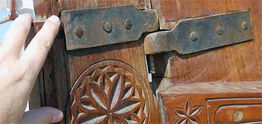
There should be enough of a gap to keep things secure. Use extra and file back to the correct shape. Pic is of the rudder post (left) and stern post (right) on an Arab craft. Pin on rudder drops into the gudgeon on stern post, gravity holds it in place. Yours probably has more of a zig zag edge where the pintles are set in a notch in the rudder post.
- 1,306 replies
-
- 8
-
-
- syren
- model shipways
- (and 1 more)
-
Epoxy comes to mind for the pintles, but a pic would help.
- 1,306 replies
-
- 5
-
-
- syren
- model shipways
- (and 1 more)
-
Look on your plans, see if they have given you some contours to carve these blocks to.
-
Catching up a bit: I really like your copper plate stamp. Just the few pictures you've put up make the method really clear, thanks. In future, to make a piece, like your cap rail, with a flat bend, you can make a laminated assembly with several square lengths bent around the curve. Use a series of pins or nails set to the curve, or cut a block of wood to the curve and use that to determine the curve as you glue additional lengths of the square stock. A piece of plastic wrap underneath will help it release. If it's all the same type of wood, the grain shouldn't be too noticeable.
- 1,306 replies
-
- 5
-
-
- syren
- model shipways
- (and 1 more)
-
The snaking (cross stitching between the fore and main stays and preventer stays) I have recently heard, might be only put on for action. Your thread at each stitch line, or seam in the sail, might be wood or metal hanks, loops around the stay and sewn to the sail. There might be a line put up for the staysails, parallel to the stay.
-
Thread for sewing comes in basically standard sizes for the purpose; button and carpet, embroidery, normal sewing. Commercial sewing probably has more sizes, for bluejeans, tarps and other canvas-like materials. You'll have to test some out for your purpose and scale. Some of the really small linen stock is for sutures, so no strands, just a single twist. It goes in and comes out easier that way.
-
Steam tool for bending wood model ship planks?
jbshan replied to mobile1's topic in Modeling tools and Workshop Equipment
A wet paper towel and a microwave. -
Work the joint down, offering the work piece up frequently to check for fit, until you are taking two licks with a piece of kleenex between trials. Whether you use knives or chisels or files or sandpaper or milling machine or laser, you want to end very carefully and gradually. Do only one end at a time. Get it perfect and move to the other end. If you try to do a whole piece at a time, a change at one end will knock it off at the other. This goes for anything, plank, deck structures, spar making etc. and so on.
-
Final installment: Now that I’ve disallowed most of the usual suspects, I can report on the one source I have that is incontrovertible, Vasa, which has been published to some extent, including the deck plank on all the surviving decks. She’s far too old to be absolutely reliable for the 1760 date of the original question, but relevant to the extent that joints exist in her planking that were used much later, showing that the percentage of use of one or the other may have changed, but that they knew about and used all the joints used hundreds of years later. The lowest deck is deep in the hold, I suspect laid to keep any stores out of the ballast. This deck was mostly clear, the stores not having been yet brought aboard. It is laid in sections, with straight plank, the edges merely being cut off to match the curve of the hull. The plank butts are in ‘seams’ across the hull, and are scarfed with flat scarphs, not staggered in any way. Presumably this would allow a section to be taken up for access to the ballast below. When the ship filled and capsized, this deck lifted up along the port edge, allowing the ballast to spill farther up the side. Next is the orlop deck. These planks are tapered with staggered butts, though there are two seams. There are a few hook joints at the waterway. The lower deck has curved plank, with less plank at the cabin. There is a seam beneath the cabin bulkhead and this is where the number of plank was reduced, along with some drop planks. There are a few hook joints, and several places where there are ‘plugs’ put in, as if there was a rotten place that was cut out and a small section inserted. The upper deck is basically the same as the lower, except there are two seams aft, the plank in the cabin being tapered. There is no quarter deck or focs’l remaining. The whole looks expedient, as if they made use of the material at hand without much attention being paid to any scheme of butts or symmetry, except that inside the cabins things are a bit neater.
-
Scuppers have always seemed to me to be too small. :-) Also, there's no reason they have to be drilled all the way through. A half depth hole from each side should work. My Niagara/Lawrence (Model Shipways) model has them lined up under the midships carronades, so I just did them from the outside.
- 306 replies
-
- 2
-
-
- armed virginia sloop
- Patrick Henry
- (and 2 more)
-
In your time frame, you could use Constitution as a guide. It needs to be far enough forward to spread the tack of the fore course.
-
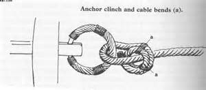
Really nice anchors. Puddening, just wrap with one line, then add as much of the fancy stuff as you can on top of it (you'll want to do a stop lashing or wrap near the shank). Nobody's going to be able to count strands. Hawse holes are where the anchor cable comes inboard below the head timbers. Puddening of the anchor ring Hawse holes
-
Well, yes, there's the rub. If you can be sure the knots are secure, but either we are so big or the models are so small, it can be hard to ensure nothing will come adrift, and if one comes out that is under several others it can be hard to resecure it. A little dab of the proper glue can give a little reassurance.