amateur
-
Posts
3,533 -
Joined
-
Last visited
Content Type
Profiles
Forums
Gallery
Events
Everything posted by amateur
-
Impressive knight. And now for the damsel in distress? The dragon, or do you have another of those heavily armed boys? I think you should gicve the shield a matte overpaint, it is abit too glaring compared to the armour. Shields were made of wood and leather, nothing shiny. Jan
-
Yup, you may consider yourself somewhat elderly Jan
-
It’s always longer ago than you first think…. I guess those two minutes of footage are remembered by everyone. Always wondered why the columbia-footage isnt so well known. I guess it is the difference between seeing something disintegrate, and ‘only’ seeing some abstract dots on the horizon. Jan
-
The structure that depth charge is hanging from, is that rolled tubes with some metal in it? Jan
-
Beautiful model of a rather bizarre type of ship. Jan
- 288 replies
-
- 4
-

-

-
- Card
- Pre-Dreadnought
- (and 3 more)
-
First lessons learned when I moved to Rotterdam: 1. always cross the tracks at (near) 90 degrees, 2. the tram always has right of way, irrespective the situation. Jan
-
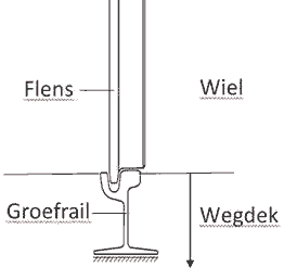
My interpretation of that pic would be that you see the track as shown in my illustrationn, and two additional iron bands (don’t ask me the function of that) outside of the track. Jan
-
It looks like a nice crowded scene. I can’t really tellfrom the pic, but your tramrails seem to stick out above the pavement. In that case it needs a little overhaul: as far as I know, teamrails was (is) always level with the surrounding street. I looked for a pic of the railprofile used around 1915 in the Netherlands: The rail hardly above streetlevel, and the groove always fun for bikers (still is ) And ofcourse: used track has a clean groove and no rust on the contact surface of the rails, disused track has some rust, and a dirt-filled groove. Jan
-
‘Wow’ sums it up pretty well. Those are really, realy close to the originals. (Apart from size and material, I see no differences ) Jan
-
Tapering Masts and Arms the easy way
amateur replied to Johnny Mike's topic in Masting, rigging and sails
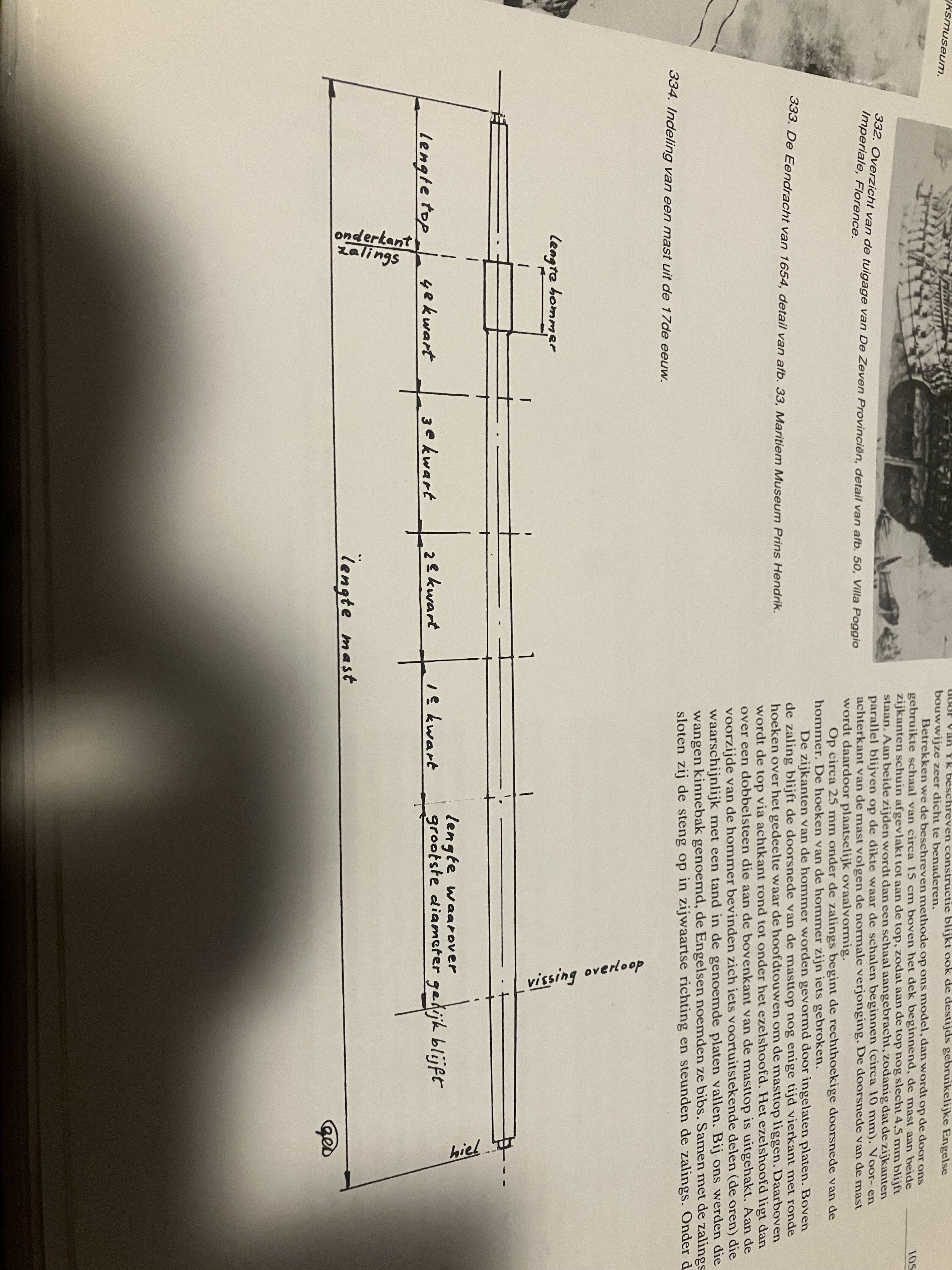
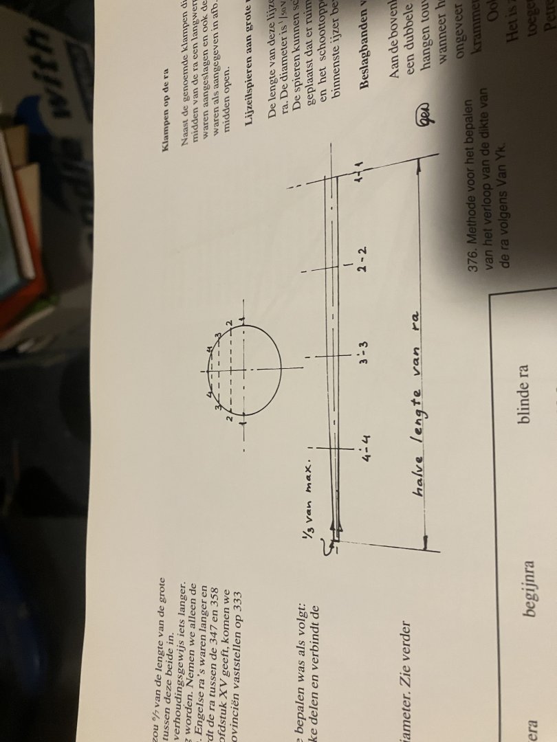
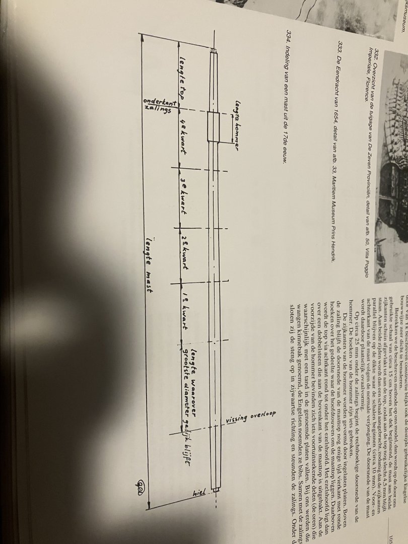
Below are three pics from my books. Not terriblt goods pnes, but I guess they will do. First the method Van Ijk (famous dutch writer on shipbuilding describes with respect to the tapering of the yards. take a circle inthedismeter of the spar. Devide the circlehalf in 8 equal parts, and connect the dots. The lenght of these lines give the thickness of the yard at the corresonding points (each half of the yard devided in four) with respect to the mast Van Ijk is a bit cryptic in his description. (And some interpretation is needed: measuring from the overloop (wich is the deck below the upper/main), the mast does not taper at all over a lenght of twice the length of the top. Above that, the taper is determined with the use of a cricle: but slightly different: not the circle is devided in 8, but the baseline in four parts. The remainder of the mast is diveded infour parts. The discussion is: where ends the ‘remainder’ His illustration suggests below the top, but in that case the top becomes very thin, as the taper continues till the end. taking the end of the mast gives a better result, but still ends up a bit on the ‘narrow side’ And with a slight variation, but showing the profile somewhat clearer: relatively thin at the mastfoot, thickest at the level of the overloop, no taper above, and a ‘circular’ taper above. the same ‘circular’ taper is used for the upper mast-parts. For my Prins Willem I used something like one-third without taper, and some taper above that. For the upper parts the taper is relatively small, so the difference between straight and circular was’t very noticeable. On the lower masts it certainly was visible. On the yards the difference between linear an circular it is very noticeable. They end up way too thin when a linear taper is used. Jan
-
Hoe did these things not get stuck in uneven terrain…? It looks unbalanced, overweight, and underpowered... But great modelling and especially great painting/weathering. Jan
-
Tapering Masts and Arms the easy way
amateur replied to Johnny Mike's topic in Masting, rigging and sails
Dutch ships may have had a single taper on mast and spars, but that was not a ‘linear’ taper. Both for masts and spars the taper was (more or less) a large radius circle, leading to spars that are almost not tapered in the middle two quarters. The same applies to the masts (even more complicated: mastheads are square, and not tapered). Your model will gain by going the extra mile of recreating that profile. I dont see how you can get to that using a sanding disk Jan -
You should also have a look at some of the build-logs of Dan Vadas. Lots of usefull info there. This one for instance, but there is more to find. https://modelshipworld.com/topic/16864-bismarck-by-dan-vadas-finished-gpm-1200-card-and-pe/ Jan
- 106 replies
-
- 2
-
-
- digital navy
- v108
- (and 3 more)
-
Markers work fine, but often just plain watercolour or acrillic paint does the trick. with respect to the side wings: i should have cut the angled pieces, and glue them, instead of folding backwards: the paper I used was slightly too thick to get a nice even bend. Jan
- 106 replies
-
- 2
-
-
- digital navy
- v108
- (and 3 more)
-
Pretty good for a braindead builder How much of it will be visible in the finished product? Jan
-
Although cheap sometimes means: crappy wood and even crappier instructions. That makes cheaper not the same as ‘easier’….. Jan
-
Did some googling. you can use that same string to determine the position of the slots in the lower chanel. You may discover that the slots in the upper chanel need some tinkering to get enough space to set them on the correct angle Jan
-
Actually, I don’t quite understand the issue at hand. To find the correct angle for the chainplates, take a dowel as dummy mast: ty a piece of string at the top (or were the top will be). Pulling that string from mast doen over the chanels, will give you the angle for the chainplates. As the angle varies from front to aftshrould, the lower end of the chainplates will not be at a straight line, but on a large diameter radius. Jan
-
How on earth did you get the ratlines to this stage of perfection?? Jan
-
Smaller than I thought. I don’t know how it is in real, but on my screen gold and colours balance out quite nicely. Jan
-
With respect to the deck-camber: from the drawings that Fred Hocked posted in the Vasa forum, there seems to be considerable camber. Also: the way you draw the bottom timbers is not completely up to 'usual standards: the timbers lay flat on the keel, the planking goes down in the keel-rabet, leaving an open space to collect the incoming water. See drawing no 6, on this page: https://warshipvasa.freeforums.net/thread/87/vasa-ship-plans?page=3 Jan
-
Coming along nicely. Those things on the reardeck are not vents: just staircases to the lower deck (at least, ghey are in the dutch Z1, that was designed and build after the first Z1 became v108) Jan
- 106 replies
-
- 4
-
-
- digital navy
- v108
- (and 3 more)
-
Sometimes I think you love card-planes better than card-ships. Is the pattern of the ribs just rendering, ordid you do something to enhance it? Jan
-
I don’t see what you try to tell us. The ridets are made from a number of pieces of timber, scarphed together and the scarf is secured with large dowels that are more or less evenly spaced. Or are those not the dowels you refer to? Jan
-
Make sure you can still get the model out of your workshop…. A full rig at that scale will be large Jan