HOLIDAY DONATION DRIVE - SUPPORT MSW - DO YOUR PART TO KEEP THIS GREAT FORUM GOING! (Only 20 donations so far - C'mon guys!)
×

Jeff-E
-
Posts
699 -
Joined
-
Last visited
Content Type
Profiles
Forums
Gallery
Events
Everything posted by Jeff-E
-
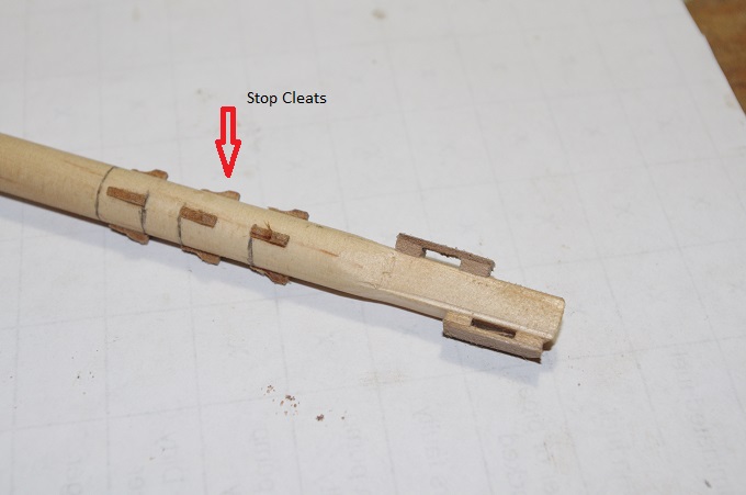
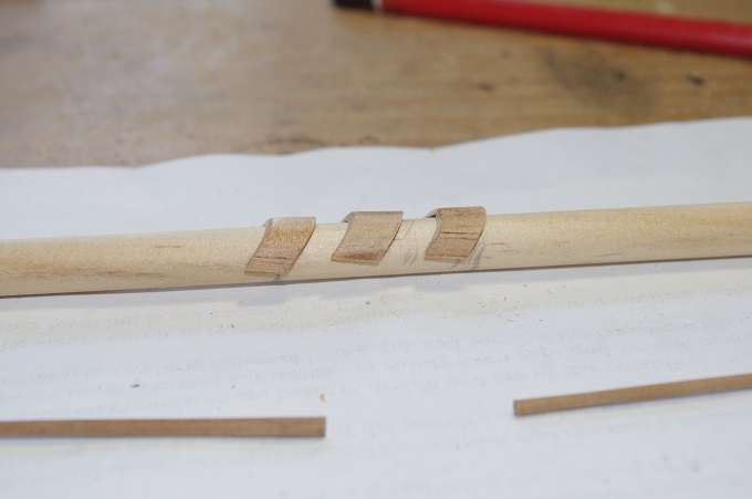
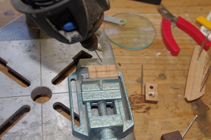
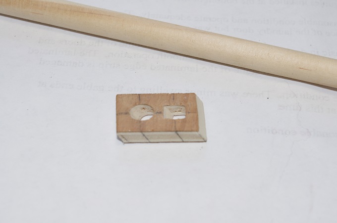
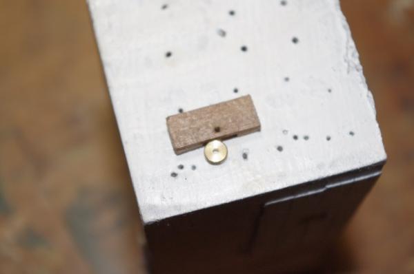
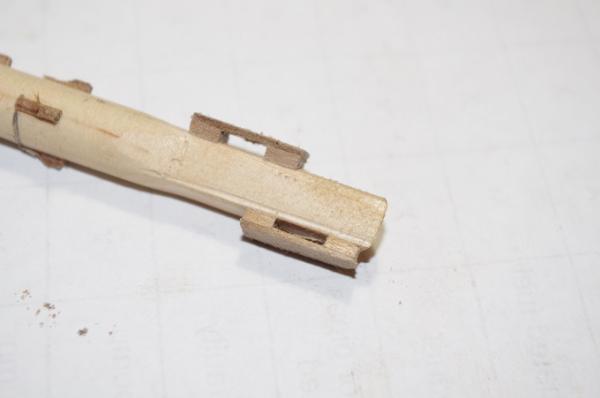
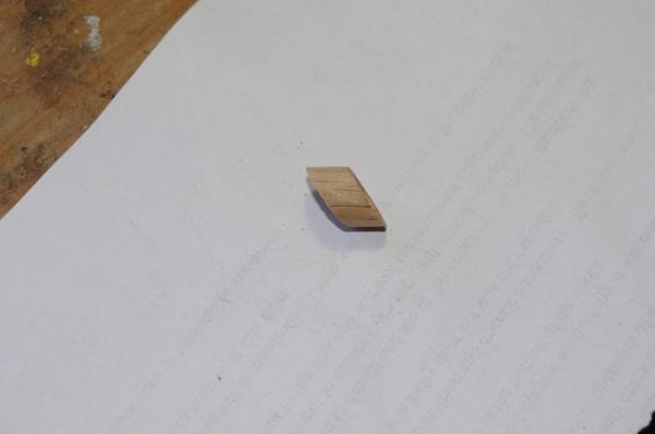
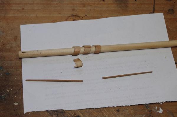
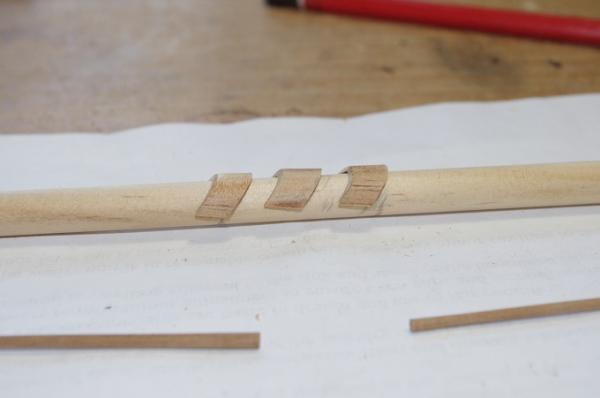
Hi All, The next stage in making the bowsprit was to make the sheave blocks for the fore topmast stay and the preventer stay. Although these lines wont be fitted to the model as the topmast will only be about 100mm long, I still wanted to have their sheaves fitted The blocks were made from 6mm x 1mm plank and the sheaves were spares I had left over from another kit They can be seen in the first two photos. To take the sheave blocks the bowsprit had to be squared at the end but only on three sides, the top and each side, the bottom is left convex. this was done for a distance of 28mm from the end as this represents, approximately, the 6' 9"length of the bees. The second lot of photos show the blocks fitted, you will note they are staggered. The front one is for the topmast stay and the back one for the preventer stay. You may also notice the stop cleats have been fitted these are for the bobstay and bowsprit shroud collars to sit against. They were made from 1mm x1mm walnut and shaped once they were glued to the bowsprit, they were also pinned with 0.5mm dowels. .


-
Hi Ken, Welcome to model ship world and this log. Thank you for your kind comments and I hope this log provides you with some ways to improve on the basic model. Are you going to start a build log?
-
Hi Bryan, Thanks for the info on the paint I think I will do the same when I get to it as it will hide the ply and laser cut marks. Very nice work on the cabins and you are right there were cabins and storerooms on the decks fore and aft of the main hold and I think you will be surprised how much you will see when the deck is fitted
-
Hi All, I made the gammoning fish next, there are three of them needed. To make these I drilled a 10mm hole in the centre of apiece of 12mm dowel and then cut off two rings at the same angle as the stive angle on the end of the bowsprit, each ring is 8mm wide. I then carefully cut each ring in half and spaced them on the bowsprit so that 9 turns of 0.75mm cord would fit between them Please note they are not glued in place yet. As you can see in the last two photos I have also made the Dolphin Striker and the Flagpole which will be attached to the cap later

-
Hi Nigel Excellent work the windows look fantastic
-
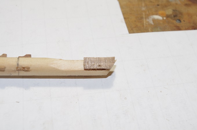
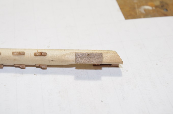
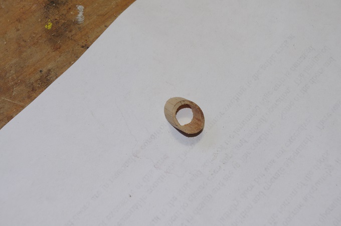
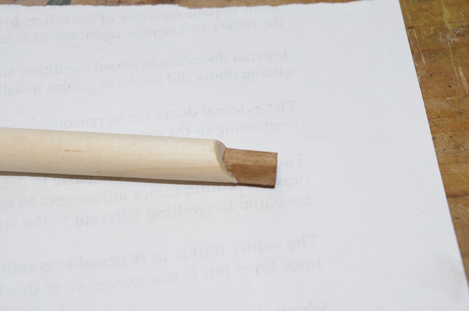
Hi All, While working on the upper gun deck I also started work on the bowsprit because I wanted to fit it to the model at this stage so it would be easier to do the gammoning now, before the head rails and gratings were fitted to the bow. I followed Longridge's description of making the bowsprit as I wanted to add more detail to it than the kit supplied version As this model is only a section the bowsprit will consist of the main spar and about a 100mm long section of the jib boom. The bowsprit was made in two parts, the main spar and a square tenon that is fitted to the end to locate the cap. The main spar is made form a piece of 10mm pine dowel, tapered to 9mm for about 200mm from the end. The end was cut at an angle so that when the cap is fitted it sits vertical line with the stem. The tenon was made from 6mm square walnut and an angle was cut on one end of it to match the end of the bowsprit I had To make a new cap because the supplied one had two holes in it, drilled square. When I tried to file the bottom hole square and at the required angle it became to large for the tenon. I drilled a pilot holes in the new one at the require angle using my dremel drill stand And then drilled the lower hole out to 5mm and squared it to fit the tenon the top hole was drilled to 6mm to take the jib boom. The top and bottom edges of the cap were also bevelled at the same angle as the holes in it Please note the tenon is only dry fitted and will be glued in place when the cap is fitted


-
Hi Bryan, Nice work on the frames, looks very square and true. What colour did you use to paint the frames? As to your query on the well around the main mast it is described in McKay's book as the hold well and contains the lower section of the elm tree pumps. I think it was a room to separate the bilge from the main hold. Hope this helps
-
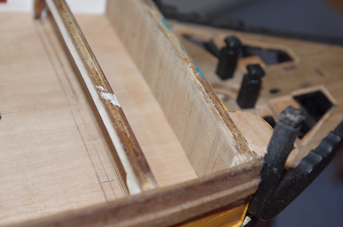
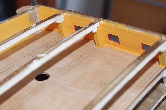
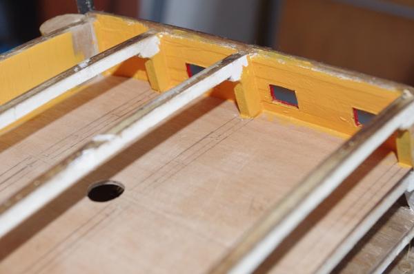
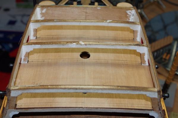
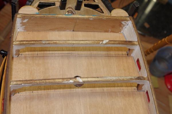
After the decks had dried the next step was to plank the inside of the beak head bulkhead and then to paint the walls. This was done before planking the decks so I wouldn't have to mask around the edge of the decks. You will notice that this deck has it's walls painted with yellow ochre. The deck planking will be the next job
-
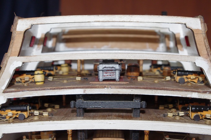
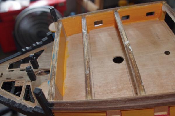
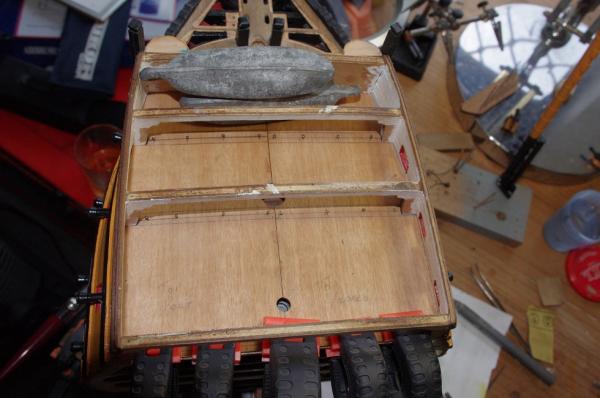
Hi All, So we move on to the Upper gun deck. The false decks were test fitted and adjusted to ensure a tight fit against the walls, the underside was then painted whit as this will form the ceiling of the deck below. Once dry the two deck halves were glued in place.
-
Hi Danny, Lovely work as always, I too will be sad to see this build come to an end but I am looking forward to your next build
-
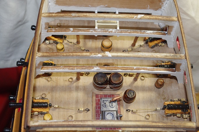
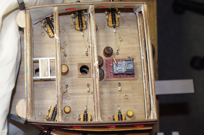
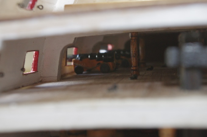
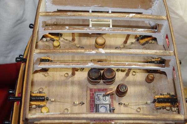
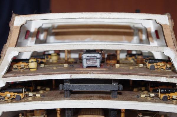
Hi All, I thought I had taken more pictures of the fitting out of the middle gun deck but all I can fid is pictures of the completed deck So the guns were fitted, rigged and the rope coils added. The stove was then fitted and barrels were placed around the deck, the two large barrels lashed together near the stove are for water and the lashing will represent them being lashed to the foremast once it is fitted, as I wont be able to access this area once the next deck is fitted. In the third photo you can see the guns rigged on the lower gun deck The next step is to fit the upper gun deck. I will post some more pictures soon

-
Hi Mark, Thankyou for looking in and your advice on the pictures I will try it now
-
Hi Kester, Thank you, I must admit I was very pleased with how it turned out even though parts of it were a bit fiddly to build
-
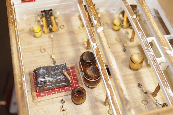
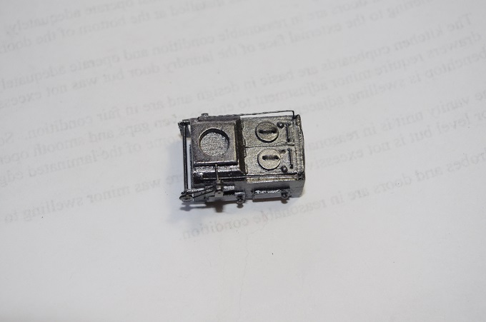
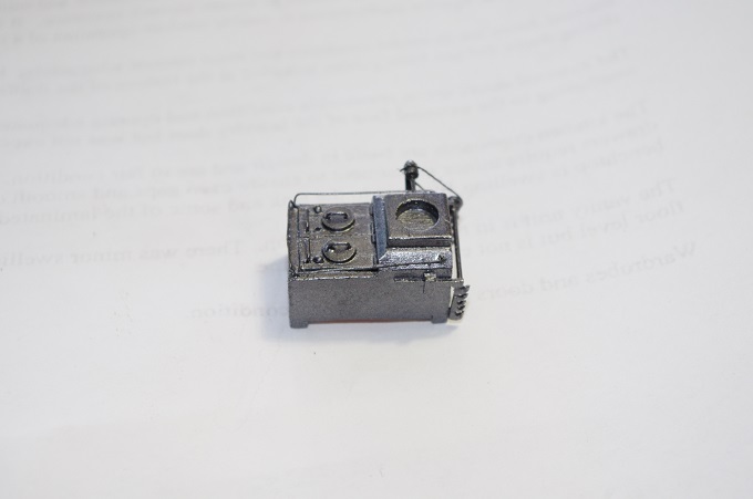
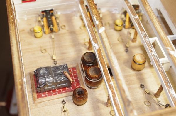
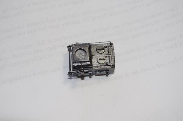
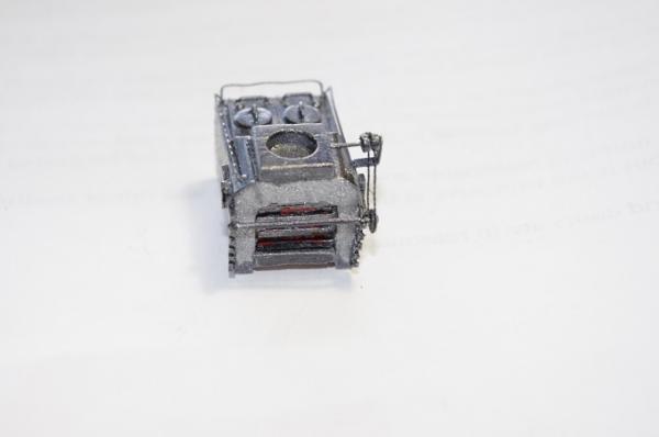
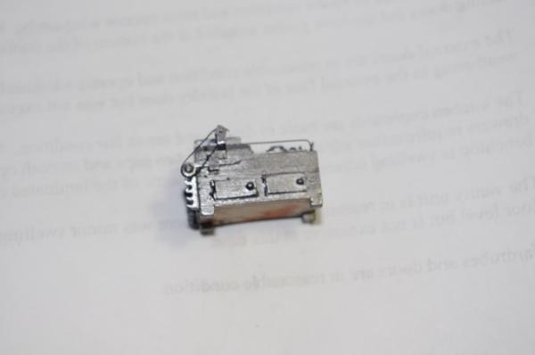
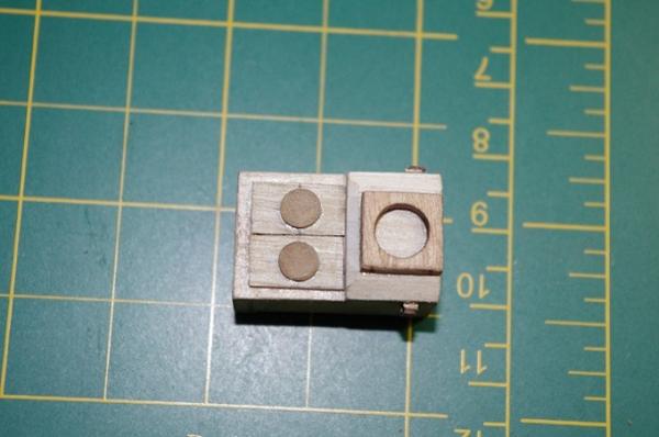
I thought I had more pictures of the construction but I can't find them so these next lot of photos are of the completed stove painted, minus the condenser and drain taps for the boilers. These were painted separately and added later A couple of notes on the finished stove. The rotisserie rack was carved from 0.5mm ply and the shaft was made from 0.75mm brass wire. The drive "chain" was made from cotton and the rails around the top of the stove were made from 0.25mm wire. The paint used was gunmetal grey

-
Sorry for all these small posts but it is the only way I can get the photos in the order I want them The next two photos show the handles on the boiler lids, the condenser and the drive wheel for the rotisserie.
-
Hi All, The following photos show some more progress on the stove. The first one shows the open grate at the rear of the stove and the second one is of the lids on the boilers.
-
Hi Kester, Thank you for your encouragement. I have seen a few of the photos online of the stove only I can't find an overall picture of it, however the pictures I have found are very similar to the drawings in McKay's book . The condenser will be fitted and the rotisserie rack at the rear will also be replicated. I am fairly satisfied with the guns but the breech rope rings are a bit to large, they probably could have been trimmed down a bit more
-
Hi Nigel, Thank you for your kind words. Yes it does differ from the 'normal' cross section which is through the main mast. The basic kit is fairly good but I think it does need some modification to enhance it. Maybe we will see you building one soon
-
Hi Anthony, Beautiful workmanship!!! You have created a detailed and accurate cross section of this famous ship. Congratulations on the completion of your build I'm looking forward to the next one
-
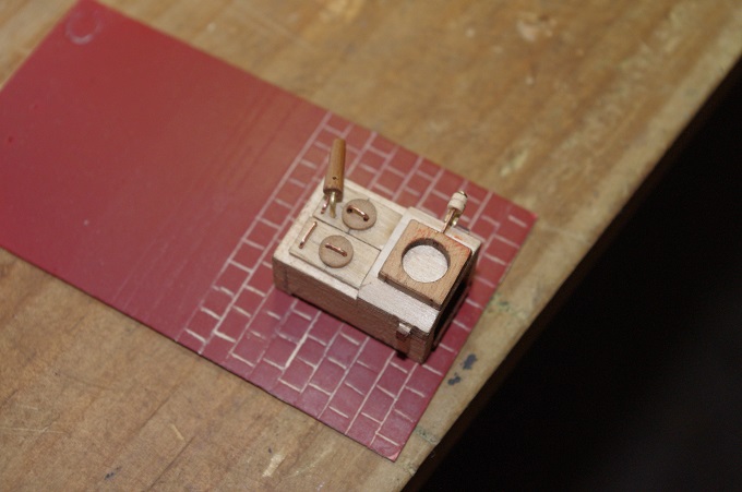
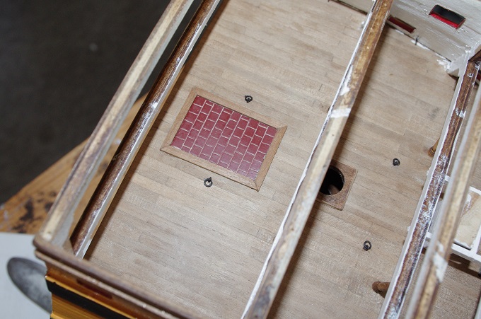
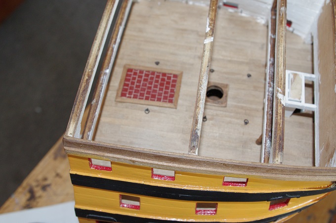
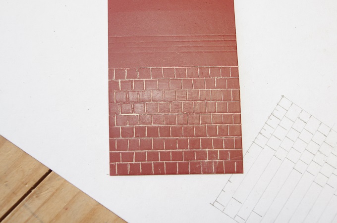
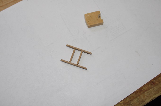
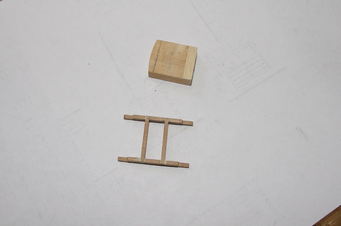
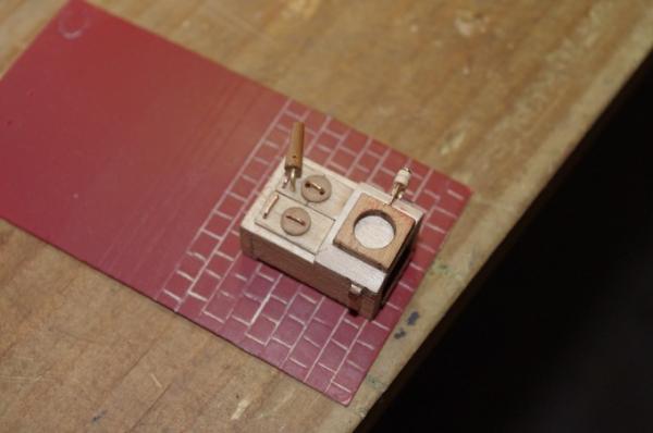
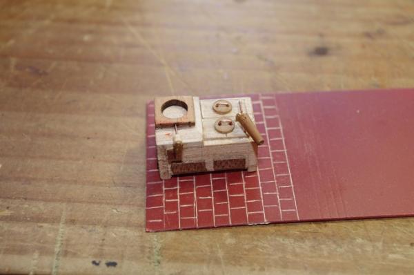
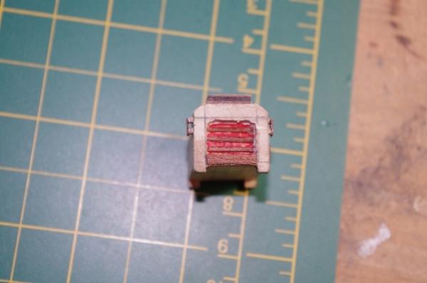
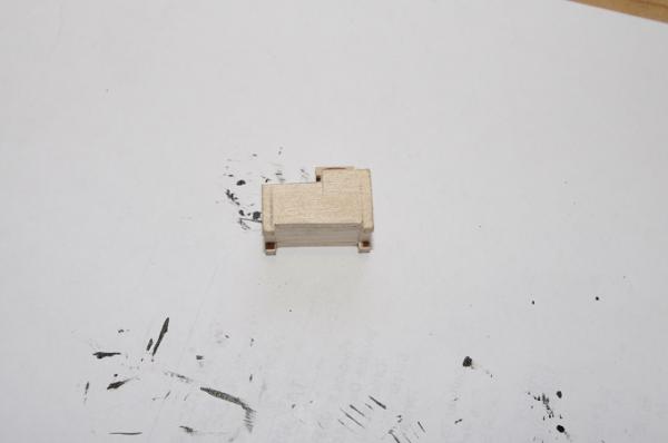
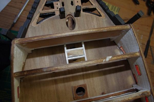
The hearth was cut out of the card and a timber edge was added to it and it was fitted to the deck as shown in the first two photos. I realised after it was fitted that the shape of the hearth was not rectangular as I have depicted it but more of a triangular shape with the top cut off. However I did not find this out until the stove had been fitted and it was too late to change it. Also notice that the eyebolts for the gun train tackle have been fitted. The stove was modelled on the Bounty's stove in McKay's Anatomy of the Ship which is probably not what the Victory's stove looked like but it is, I think, an improvement on the kit supplied part. The first two photos show the hearth fitted and the next two show the start of the building of the stove. The main body was carved from the supplied lime wood block

-
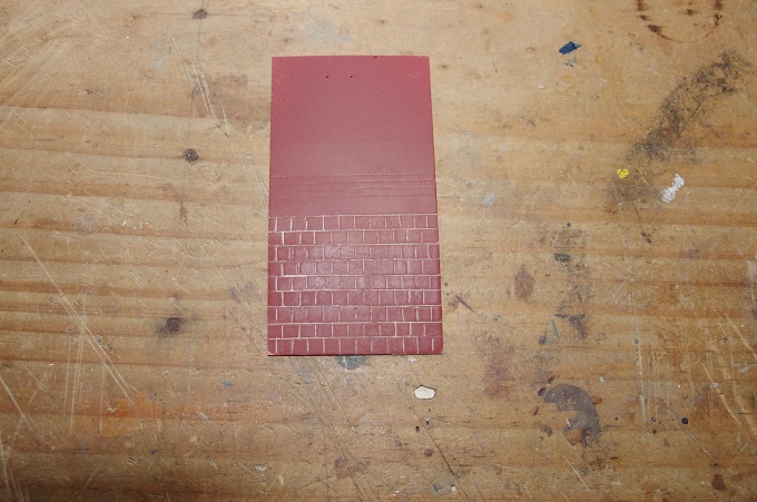
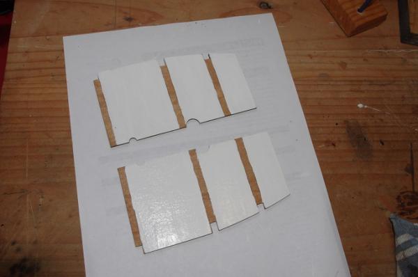
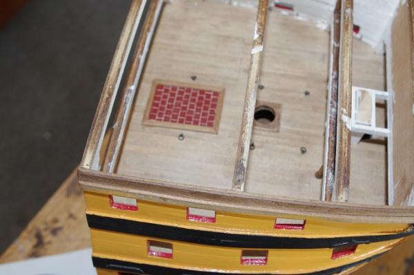
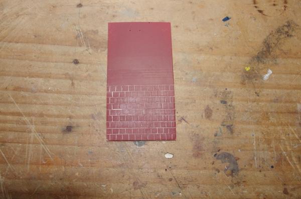
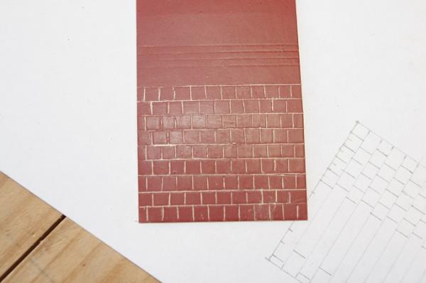
Hi All, Thankyou for all the like hits. Just a quick update on the middle gun deck. This deck was where the galley was located, the kit supplied certain parts to build a stove which are shown in the plans in the first two photos. I decided to improve on this basic model and add a few extras. The first being a hearth, this was made from 0.5mm card painted brick red and then lines were cut into it using a hobby knife revealing the white lines shown in the photos to resemble the grouting between the bricks
-
Hi Bryan, You have made a great start to your kit. I also have this kit on my shelf and it will possibly be my next build after I finish the Victory bow section I will follow your progress
-
Hi Danny, Just been catching up on your build after a long time away I cannot find the appropriate words of praise to describe your work absolutely stunning.
-
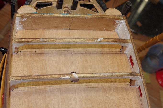
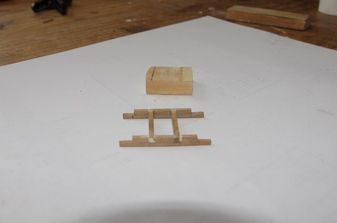
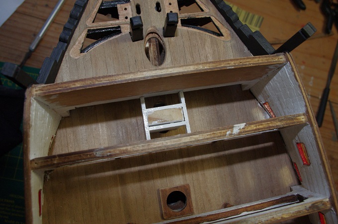
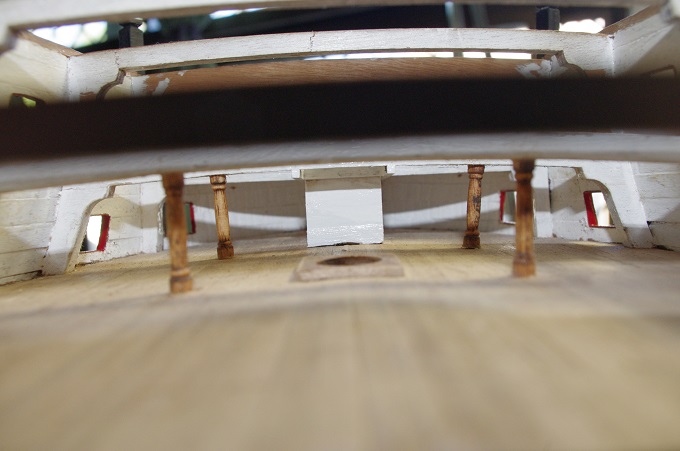
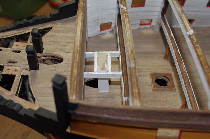
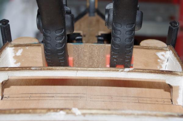
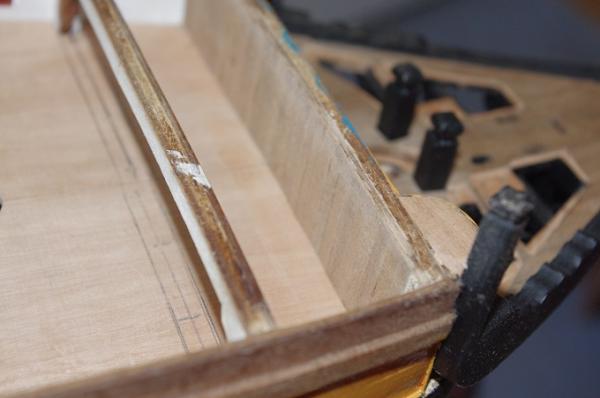
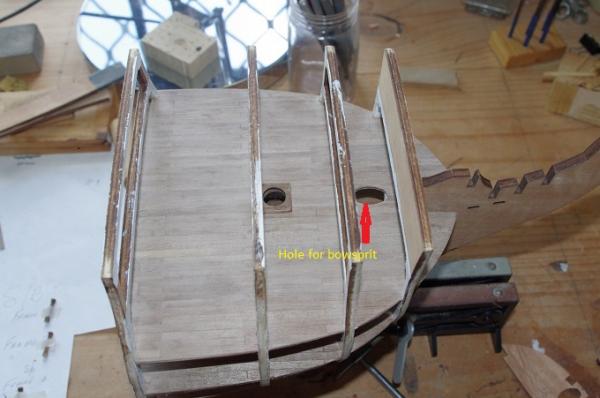
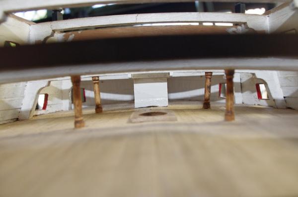
The next stage of the build was the middle gun deck. This deck was where the bowsprit heel was located and the galley. The model has a hole in this deck through which the bowsprit is meant to pass and then terminate on the lower gun deck which it is not supposed to. To over come this I made a heel and support so that the bowsprit terminates on this deck, the heel was made from 8mm X 19mm Tassie Oak and the support was made from 3mmX 2mm Walnut. The support fame was notched to fit under the beak head bulk head and the first crossbeam . The first photo is an earlier construction photo showing the hole in the middle gun deck for the bowsprit to pass through to the lower gun deck. The next three show the construction of the heel and frame and the last three show it fitted to the model and painted


-
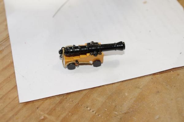
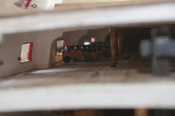
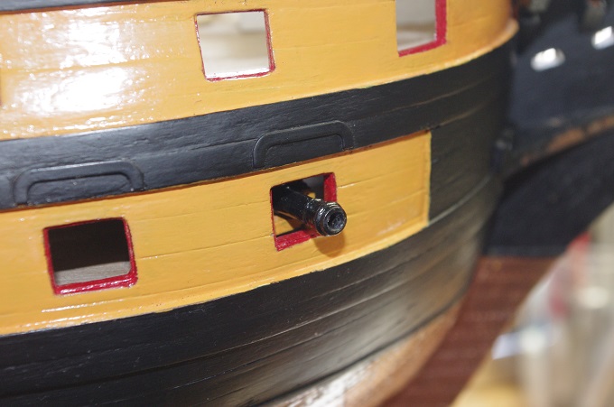
Hi All, Because the lower gun deck has been enclosed it will be impossible to fully rig all the cannons on this deck. The first two guns from the bow will only have the breech rope fitted, this will be a shortened rope with no eyebolts as these can't be seen when the other guns are installed and they would be very hard to fit to the hull if not impossible. The other two guns will have fully rigged breech ropes and side and train tackle, however the side tackle will only be on the aft side of the gun I'm sorry I don't have any photos of the rear guns at this stage of the build but you will be able to see them in future posts