dafi
-
Posts
2,430 -
Joined
-
Last visited
Content Type
Profiles
Forums
Gallery
Events
Everything posted by dafi
-
 Longridge and Heller describe an anachronistic version, also this was shown in P. untill some years ago. There the line with the block is kept clear the hull with an iron bracket and this is only post Trafalgar if I remember well. I think the bishop version is closer to Trafalgar but it should be researched again. Perhaps Lees tells something It could be, that the block was quite near the hull, but the hanger on the yard was much longer. XXXDAn
 -
Message for John Walker: Can you please try to contact me here in a PM? All the best, Daniel
-
Great work, Bill, love it! As Kevin asked for the copper color scheme: Blank as Bill´s copper it only is if polished 🙂 As for my resaerch, the greenish color just appears if copper is on the air, like in the drydock. Usually in the harbor the copper gets a brownish color. Usually with all kind of weed on top. If sailing the abrasion of the water molecules give a pinkish (!) appearance to the "delight" of the most model makers 😉 So basically on can show on the model, what happened last to the ship. Was it in harbor or was it sailing. In some test pieces I opted for a mixture of brown and pink for underneath the water, for a bright pink on the waterline and a very thin greenish erea where wind and weather meet. All the best, Daniel PS: Some more infos about copper and aging here in German, but one can use the automatic translator on the left bottom.: https://www.segelschiffsmodellbau.com/t588f643-Kupferung-im-Original.html https://www.segelschiffsmodellbau.com/t3568f804-Patina-von-Kupferteilen.html https://www.segelschiffsmodellbau.com/t3567f804-Kupferung-Darstellung-von-Naegeln-im-kleineren-Massstab.html
-
Not all problems with the Heller instructions are mistakes but anachronisms due to advanced research today. M24 is shown here with a kind of three-legged rope, as it was some years ago still attached to a three-legged iron structure to keep it clear the hull. It was later realised that this was introduced only much later and today shows a single Rope fixed on the hull. Same goes to the 2 eyebolts near the cutwater on the bow. Those ropes are omitted today but the bolts were still visible until the last restoration. Are they still there? Great work on the plates, looks like I was right to tempt you 🙂 XXXDAn
-
Hllo Bill, sorry to be absent that much, had some sad family business to take care of. The batten that finishes the copper was done in mid february 2011. Have a look, I have only restricted internet here in the Austria´s mounains. XXXDAn
-
Hello Pete , sorry for the late reply. Yes the family is safe and sound even thogh my brother in law just lives 1,2 km from this infamous earth slide that went throug the international media. He was very lucky, even being that near, hiss house did not even suffer a water stain. But the area was build upon sand - quite biblical - and one one of the facilities that were hurt was a castle, standing there for centuries ... XXXDAn
-
Now to be serious. I do not want to interfere into your build, but as you ask questions and when I see some realistic potential, I then will tempt you, but I will never disrespect your way of building. Just tell me to stop in a PM, be assured I will respect 🙂 XXXDAn
-
I am on the go since 12 years and funnily you most possibly will overtake me at your month 3 ... Thats why I am trying to distract you 😉 XXXDAn
-
If I remember well, it was about 1 roll. But as usual, no pressure 🙂 XXXDAn
-
Still tempting you: As you like the blanc rigols, did you already consider to plank the bottom with real copper? With the tiffany self adhesive copper tape it is not a too big task. Stuff is quite cheap and the effect great. Measure if you need the 4,0 mm or 4,4 mm tape and try out on a piece of plastic. That you painted already is a good base, so you do not have black flashing through eventual gaps 🙂 All the best, Daniel
-
Wonderful place! XXXDAn
-
Great Job!!! XXXDAn
-
Just discovered now, wonderful and pleasant project and a great result! All the best, Daniel PS: AND NO! I am not cutting down my one 😉
-
Oh great, they are adding weathering effects to look more realistic 😉 Hy Bill, basically the lines look good. If I remember well, the Heller lines are different from one side to the other. Also the old rule said to follow the gun ports as you did, probably as for the Nelson checkers. Newer resarch also indicates, that the checker could have not been there at Trafalgar and the lines followed the wales. So the choice is yours 🙂 Just have a look that the lines look harmonically, running smooth and also that the widths correspond to each other. And I think it a good idea to fix the side galleries temporarily to better judge the situation. Great job on removing the old balusters. As for the small scars in the surface, do not forget to fill up with some putty. All the best, Daniel
-
As to be indicated on Lifesay´s drawing of the stern and as also mentioned by David Steel***, the outer windows of the stern could have been be mock windows. That is what I have done. ***The Shipwright´s vade-mecum, p.180
-
First rigols, then paint 🙂 🙂 🙂 Great Job you do! XXXDAn
-
I like the "Art Brute" Plenty of 1 mm holes in safe distance to the edge, all around the frame, then the scalpel and then the files 🙂 For this, even I use a motordrill 😉 XXXDAn

-
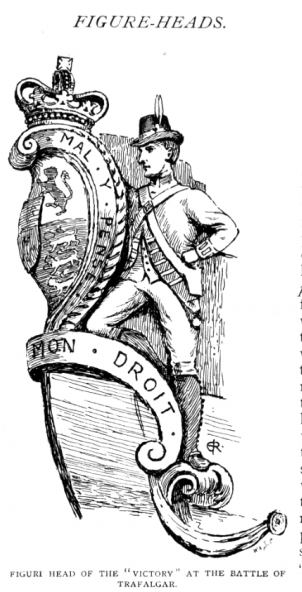
Do not think so 🙂 I think there is a misinterpretation that got its own life. As the culprits had a red and blue scarf there was the interpretation them to represent the marines and sailors. It appeared that the damages the culprits took - one left an arm, one a leg - were coincidenting with the major wounds of the 2 groups at the battle. And this took a life on its own ending up in the believe that were a marine and a sailor standing beside the coat of arms. But that is imho. The article publishing this picture originates from 1891, so it is not contemporary. Also the Independent revealed that since approx. 1815 both of the Culprits were on board 🙂 https://www.independent.co.uk/news/uk/home-news/hms-victory-royal-navy-battle-trafalgar-b1799397.html?fbclid=IwAR1tZj6hC8OtZAaXlQtRrkZbT_ohxLmznkYIvSj1t82CGkgjvAPcVjbcOUo XXXDAn
-
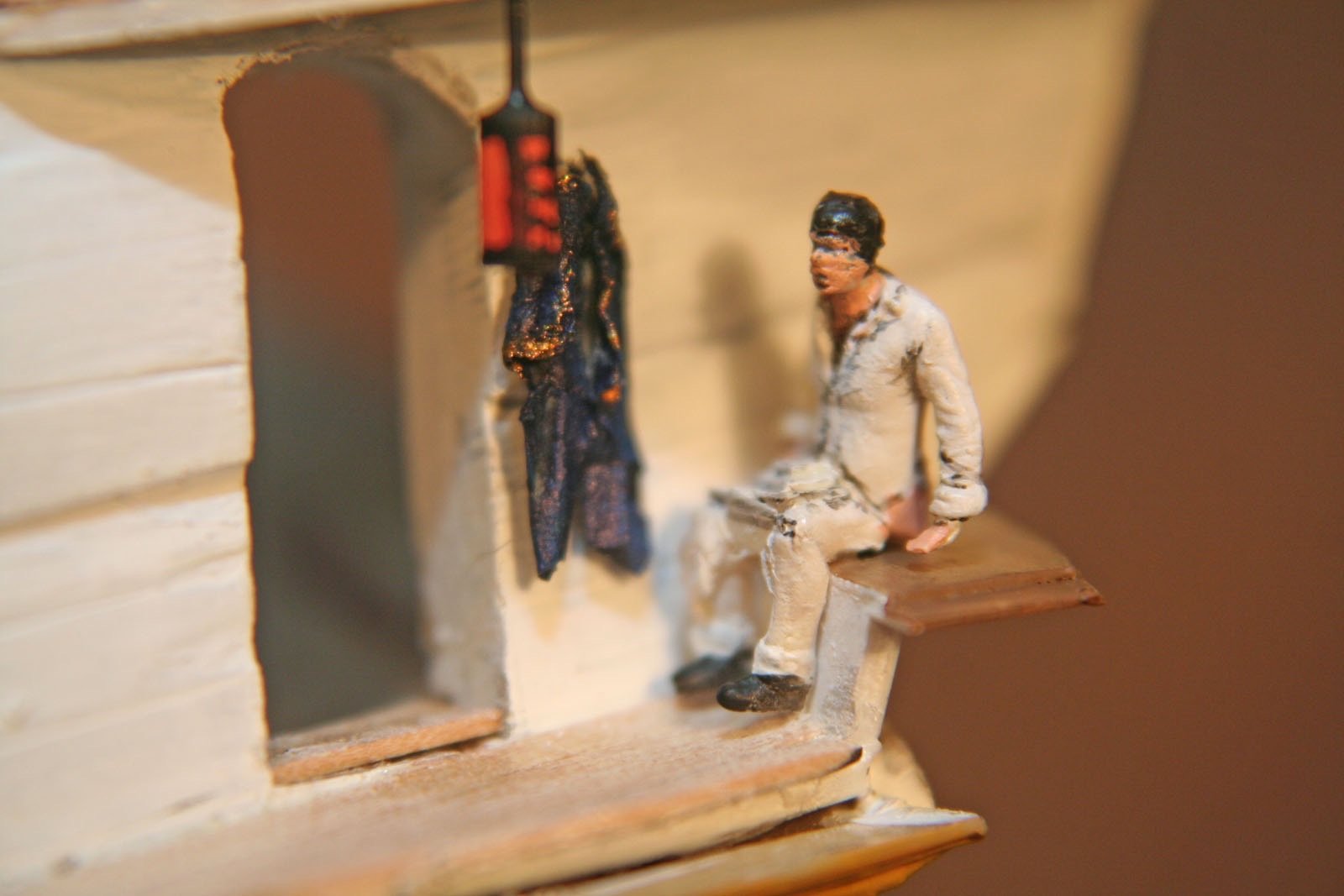
And an easy but effective one still: open the lower door to the side galleries*** 🙂 XXXDAn ***if you dot plan to put someone there seeking privacy 😉
-
Forgot to say: Rest is looking great 🙂 Do not forget the enlarging of the wales in between the fenders. XXXDAn
-
To be honest, the holes for the gunport lid lanyards appear quite messy on the pictures. Did you drill them with a motor drill? Looks like the molten material enlarged some holes quite a bit. Would you perhaps consider to close them with original Heller sprue, heated up and pulled into right thickness and then stuck in and with plastic glue sealing the old holes? This would give a great base for the new holes as it is then a homogenous replacement with the hull. For the new holes use a pointed scribing iron to mark the exact place first and then drill a hole by hand using a 0,5 mm drill 🙂 If ever later a bigger hole is needed, it is not a problem to enlarge the holes with another drill - also done by hand. If it sound good, just try out on one port first, before takling all the other ones. All the best, DAniel
-
I usually do both 🙂 The reason is very simple. The painting might leave some microscopic places blanc and once the light shines on, it then might call a lot of unwanted attention. I had to realize this already long times after finishing a project, suddenly with the right (or better wrong) light one sees a nice golden blink. With blackened parts this does not happen. But even with black there are more than 50 shades of black 😉 So with overpainting blackened part with a thin touch of paint, the parts will blend in perfectly and no shiny monsters will appear 🙂 All the best, Daniel
-
Hello Bill! Bahooooooooo and off we go!!! Basically any blackening product will do. I use the cheap one from Krick, not the best but works. Take a small glass bottle and poor enough of the stuff in, leave the parts in over night. Take the parts out and rinse well. Before glueing take care to scratch off the black stuff or the superglue will only hold the black stuff back and not the brass inside … I just blacken the pieces as they are. If ever the parts do not take the blackener in, try a solvent first, if no reaction then try another brand. Smaller parts I leave on the sprue, as they would be difficult to retrieve. Also there are blackners that can be applied with a brush.They usually also work faster. Then one can easily „paint“ the parts on the sprue.Have a search in MSW for the theme. But even blackened I apply a thinny coat of the surrounding black color for that there is the same shade. Bigger parts that can be retrieved easily out off the soup I take off the sprue before blackening. XXXDAn