dafi
-
Posts
2,434 -
Joined
-
Last visited
Content Type
Profiles
Forums
Gallery
Events
Everything posted by dafi
-
 Just the way there was too much for old little heard especially the last 47 Minutes, means everything past the usual 90+ mins. And very much the last 17 minutes ...
 -
After the match yesterday was **** for my nerves, I had to calm down doing some of my favorite themes ;-) Plumbers work. The drain angle could be possibly optimized towards then windows or - as Livesay indicates - with mock windows the drainage could even go down straight, possibly hidden behind a curtain wall. Does anybody know contemporary details about that?. Also the front got some discharges to go around the window underneath. Here I chose to point it aft for waves not to get stuck in it and shower the roundhouses inside. XXXDAn
-
H.M.S. Victory Fore Topsail Braces
dafi replied to JerseyCity Frankie's topic in Masting, rigging and sails
Petersson belays it on the rail just beside the belfry, so not too far off the place you give. XXXDAn PS: Not to forget - the waist was not as open or accessible as on most models / plans as all the boats and spare spars were cluttered there. This too should be respected when belaying!- 4 replies
-
- 3
-

-
- HMS Victory
- rigging
- (and 2 more)
-
As always: WHAT a treat! XXXDAn
-
Since a while I am observing the different versions of the metal hammock crane holders and their positions. Therefor I am looking for contemporary sources of this rarely shown detail. HMS Victory 1765 http://collections.rmg.co.uk/collections/objects/66473.html SLR0512 Scale: 1:60. A model of H.M.S Victory (1765) made entirely in wood that has been painted in realistic colours with metal fittings. [...] The poop deck fittings include a rectangular skylight, launching flag pole, [gruen]hammock stowage rails[/gruen], and provision for an ensign jack staff. [...] Date made Mid-18th century Warship(1745); Third rate; 70 guns Read more at http://collections.rmg.co.uk/collections/objects/66431.html#SRxOXkziYoHbXrqM.99 SLR0470 Scale: 1:48. A full hull model of a 70-gun, two-decker ship of the line. The model is decked and equipped. A plaque on the original base is inscribed ‘Lord Nelson’s model of H.M.S. ”Ruby” built in 1768. Lent by Capt C.A.R. Hoare’. [...] This model was formerly known as ‘Lord Nelson’s model of the Ruby’, but its proportions are quite different from those of the only possible ship of that time: the ‘Ruby’, built 1776 at Woolwich. The fleur-de-lys decoration suggests French origin, and it is possible that the British Royal Arms in the stern galley may be a later addition. The general appearance of the model, however, is not in the least degree French. [...] Date made circa 1745 Interesting is - also seen on the Vic - that the quarter deck cranes are hardly higher than the rails, making them seem useless. The inner stanchion looks to be integrated in the rail. Warship; Frigate; Amazon class; Fifth rate; 32 guns http://collections.rmg.co.uk/collections/objects/66276.html#bygQPW2IQecg1j0u.99 SLR0315 Scale 1:32. Built at this slightly larger and unusual scale, the model is a fine example of the Georgian style of modelling, with a fully planked hull and partially planked decks. [...] The model has been made to a high standard of workmanship and includes some fittings not always shown, such as the compass binnacle just forward of the wheel, shot racks between the guns, the hammock-netting stanchions and swivel guns on the ship's side. Date made circa 1780 The cranes are pointing outside the hull. Here another variation: Cranes outside and a board underneath 36 Gun Frigate http://collections.rmg.co.uk/collections/objects/66604.html SLR0643 Scale 1:48. A contemporary full hull model of a 36-gun fifth-rate frigate (circa 1801). [...] The model is mounted on launching cradles and the fittings on deck include stovepipe, hammock irons, a double wheel and capstan. [...] This model seems to illustrate something of a hybrid design for a frigate, with dimensions similar to ships of 1780–85. However, the appearance of the enclosed waist and solid bulwarks, introduced to give more protection for the gun crews, with square-cut ends are a characteristic of 1800 or later. Date made circa 1801 And merry goes round all the way the rails: HMS Duke of Kent (circa 1809); Warship; 170 gun SLR0660 Scale: 1:96. A full hull design model of the Duke of Kent, a proposed 170 gun four-decker ship of the line circa 1809 which was never built. [...] Date made circa 1809 Do you know any other contemporary sources? Thank you, Daniel
-
Thank you for the correction :-) XXXDan
-
THE 74-GUN SHIP by Jeronimo
dafi replied to Jeronimo's topic in - Build logs for subjects built 1751 - 1800
Wonderfully done! Especially love that the takles are all belayed and not just lying around loose :-) XXXDAn PS: And thanks to Mr. Delacroix to be behind and to keep on correcting the imprecise data from M.´s "bible" regarding the "continental" carriage.. -
I think one gets easily tricked by the fact an iron anchor as a very heavy object. Just some thoughts to jud´s interesting question: The cat hook is to be hooked in as soon as the ring breaks the surface. This can be seen nicely on the famous picture of the Royal Sovereign with the little man standing on the anchor´s stock handling the cat block´s hook. At this moment the weight of the anchor is far less as it is not its weight of iron but only the one of the displayed water, which is - if I am right - 1/7th of the weight of iron. Afterwards the cathead, cat tackle and all the other rigging parts of the fishing rigging have to take the whole weight of the iron. As the ship is always drifting with wind and current, the anchor cable always will have a certain direction a forehead. The ship should neighter run over the anchor, so a turn backwards of the cable was less favoured. Also breaking the anchor was often done by the big boats means there should usually not be the pull spill-hawse-downwards. So the pull downwards is far less than expected imho, but I do strongly believe, that a ship an a long cable, especially in a strong gale, will pull with a multitude of the anchor ´s weight. So it makes for me perfect sense to have the hawsers horizontal for that case, means in the direction of the ship pulling on the cable and having the minimum of breakage risk or chafing in those moments :-) XXXDAn
-
I knew it! I KNEW it! I knew I took pictures while taming the lions :-) Here is the addendum´s addendum. Yes that thing in the right lower corner is my scalpel. Some more before-after shots. XXXDAn
-
Bern in Switzerland at night and it rains cats and dogs. Lovely city with wonderful arcades and beautiful shops, but all closed by this time. To wet to do anything else so I sit underneath the arcades in front of the hotel and do some more addenda - bad luck for you lot ;-) If being fed up with gross motor skilled work like the planking or skylighting, I still had something else to do. As I already knew that I will need two more figure heads, so i decided to do a decent one, and this time to hopefully do a casting of it. Here are two Heller originals. and even here one is less crisp than the other and even that one has the appearance of an old chewed and sucked out chewing gum … … that is why I spend several nighttimes giving some TLC wich the help of my scraping skills and a scalpel … … and no, the red is no blood, it is only Edding marker to have a control what i was doing. And suddenly the horse started to jump, the harp harped again, the ice bucket rebecame Charlemagne’s crown and the duke´s hat behated everything once more and the undercuts finally cutted under … … only .. … only the lions where not be be revived by this treatment, so I replaced them by thin sheet like I already did with figure-head.1 :-) And to crown the assembly … … massacred the old crown … … to serve as a bending template for the replacement. Hollowed the base … … and checked how much space was under the spriet mast. Shortened the top accordingly … … and it looked good :-) O yes the small lettering was also fixed. After using pincers and paint, after spray glue and CA I tried something new, transparent Post-its Cut in small stripes … … and catch the letter with the sticky side - the transparent allows to see the orientation - applied little CA … … placed it and used something pointed to press against the surface … … and it fits :-) XXXDAn
-
Oh those marvels of modern technology. Sitting in the car towards a job in Switzerland and being able to update some of the late progress***. Not much was possible, just small bits late night, so one had to find the right subject - I found one, not too far off :-) I love the small etch skylight, but as all etch it misses a bit of depth. Long time I wanted to try something. First glued some 0,25 mm sheet onto the back of the roof using CA … … cleaned the edges, drilled the holes and opened the windows with a file using the brass as template … … and then separated the parts very caaaaaaaaarefully using a scalpel. Then cleaned the back of the roof and glued the clear sheet onto it by just applying CA on the edges to minimise fumes and mess … … and glued the sheet back in place thus resulting into a nice three level sandwich brass-clear sheet-normal sheet with a nice edge with the right thickness :-) The sides went alike, first clear, then normal, this time using Evergreen for the glazing bars fixed with UHU-Plast. Like this, the „glass“ is nicely packed in the middle. The lower part was left longer on purpose as this gives a nice anchorage on the deck. Still added the deck beams … … and it already looked rather cute … … even reflecting in the light. Even though I used clear sheet, how was the original glazed? Using mica for the advantage of not breaking? Or old fashioned very disturbed glas? Cheers, Daniel PS: ***Do not worry, my colleague is driving ;-)
-
... just like the left- and right hand layed shrouds Mondfeld published in his (in)famous book. That was THE TRUTH for many-many modelers for decades, until proven wrong (and later admitted by M.). On the other hand there are sometimes multiple truths. Not just only one version - so a proven fact is only one possibility. See the section in Steel about the made masts and see the so believed original artefact of Victorys fore mast with a much simplified assembly. Cheers, DAniel
-
Thank you B.E. :-) :-) :-) I took the liberty to add them to the spoiler list, always owing you credits to your always sharp eagle eye and cerebral database! Rare to be matched! XXXDAn
-
The best source is the mentioned Victory-forum at http://pete-coleman.com/forum/, especially for the Heller kit :-) The kit represents the ship quite faithfully as it was believed in the 1960ies to have looked like at this special October, 21st 1805, but since then "latest resaearch" revealed a lot of changes, not only for the color and still things are changing ... And always to point out: The Heller kit in itself is a wonderful start and was really state of the art in the 1970ies research and production wise, but simply is outdated a bit. Most important: The form of the hull in itself, the stern and side galleries are imho the most true full of all the kits available - plastic and wood !!! Not to give frustration upon all the brave Vic-modellers up to date, I strongly suggest only the bravest of the brave to have a look in there, and if so, to have all their sedatives, tranquilizers, calmative and defibrillators in reach, (ok, just kiddin´!) Cheers, Daniel
-
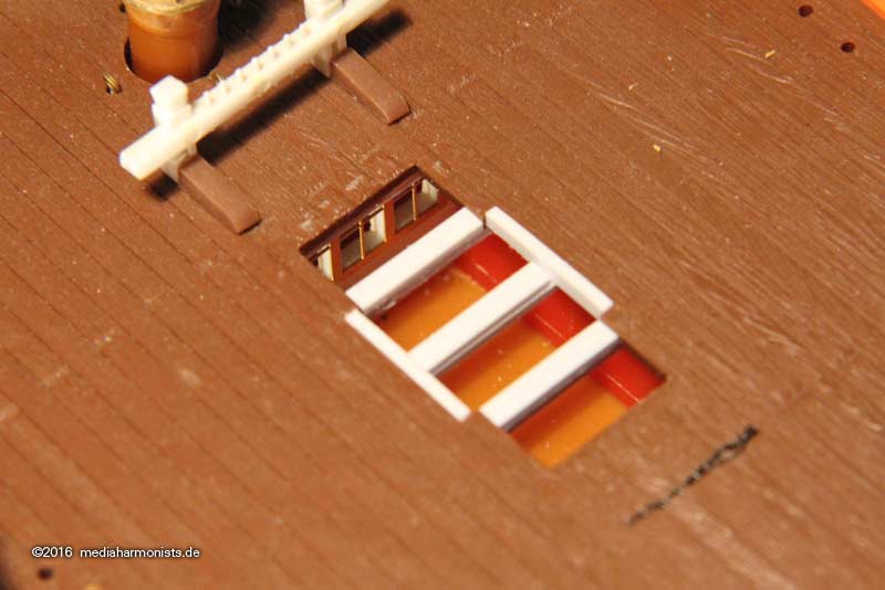
And anyway, the new position makes much sense, as it is much more centered over the room. The original Heller cut-out that is shown shown in this picture here on my unpainted model is is with its front edge exactly over the bulkhead of the cabin, leaving the back of the room dark. The black line is the optimised version shown in the previous posts and coincides with the (btw all wrong) splitline of the deck planking. XXXDAn
-
Dear MAurice, with all the good preparations you lot did at www.pete-coleman.com one can´t go wrong :-) XXXDan
-
They are parallel :-) I was not sure how to place them, but it looked strange in the area of the skylight having them curved there. Also with the two middle partners in the back. XXXDAn
-
What a sad story ... ... after the big modelers meeting in Augsburg near Munich in March my sweet black´n´yellow beaty even did not make it back up to the tinkering table and had to stay in the staircase ... ... the poor one, all alone ... ... ... :-( Until today she went underneath the knife again - HUUUUURRRRRAYYYY! First relocating the skylight of the poop. Being a little to much upfront ... ... bravely using the knife ... ... and resettling the cut out. And then something I always wanted to try out ... ... the new planking in between the binding strakes still parallel because of the 2 middle poop deck partners ... ... but then getting curved towards the outer hull. After gluing the planks cutting with a plexi ruler in several turns into shape ... ... and so I got a nice deck with curved planks and that even in 1:100, so no more excuses for the bigger scales ;-) XXXDAn
-
Caroline's bottom
dafi replied to GrantGoodale's topic in Building, Framing, Planking and plating a ships hull and deck
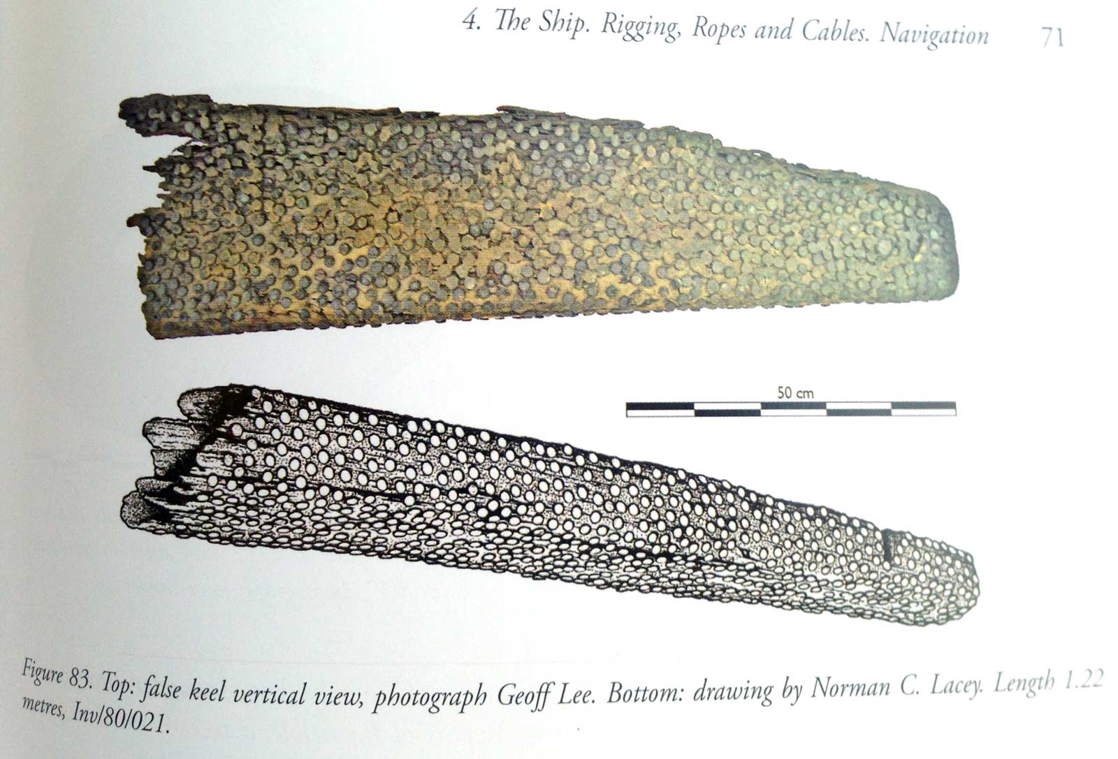
I just got the book First HMS Invincible (1747-1758) from John Bingeman There I found a picture of the false keel, with plenty of nails, could this be the "pease"? XXXDAn
-
One more question. As the gangway was originally a special feature and was positioned a bit underneath the forecastle and the quarter deck it had a own planking sceme. How was the split of fo´castle and gangway and gangway and quarterdeck handled in regards of the planking handled later on when the gangway moved onto the same level as those decks? Was there first still a split/break in the planking pattern or when did it start to be planked over as it was a single deck? In especially I am of course interested into the handling around 1803 when the vic was recommissioned still havin a very narrow gangway? Cheers, DAniel PS: Please do not refer to the 1:1 model in P. ;-) (There is a small spilt)
-
The best guessing until now in my personal opinion was for sauve-tête netting or sunsails or other "convenience"-items as there is no documentation for rigging to be attached there. But by the position of the rollers (if they are!) there is no pull pointing upwards of the line or it would have jumped out of the lead, so one could guess that these are for handling cables from the mizzen and others bits down to the quarterdeck to have more space for the men to work on the lines ?!? Cheers, DAniel