Roger Pellett
-
Posts
4,519 -
Joined
-
Last visited
Content Type
Profiles
Forums
Gallery
Events
Everything posted by Roger Pellett
-
You can either add ballast or reduce displacement. The effect is the same. Submarines use both techniques. They have “hard” tanks inside the hull designed to withstand full sea pressure. These tanks are used to maintain diving trim; neutral or slightly negative buoyancy, by pumping water in and out. To dive and surface “soft” tanks located outside of the pressure hull are used. These have holes in the bottom and vents on top. To dive, the vent is opened and water flows in through the bottom hole. The submarine loses buoyancy equal to the volume of the tank x the density of the water. To surface, the vent is closed and the water is blown from the tank with compressed air. You could use a similar system but with wing tanks located inside of your hull. Free surface effect in partially filled tanks can be minimized by one or more vertical baffles within the tank. Another idea would be to add a double bottom with vertical baffles within the hull. This would add ballast down low. Roger
- 454 replies
-
- 2
-

-
- Union Steamship Company
- Stepcraft 840
- (and 3 more)
-
Off and running with the schooner rigged pond yacht
Roger Pellett replied to Elmina's topic in Masting, rigging and sails
Steering gear could have run the gamut from a toothed rack on the deck to allow the rudder to be set at various fixed settings, to lines rigged from the tiller to various sails, to wind vane or even clockwork steering mechanisms. All of these would work with a tiller, not a steering wheel. Refer to pond yacht websites for details. -
Many many years ago my father and I built a wooden Thistle class sailboat from a kit. The Thistle is an overgrown International 14 racing dinghy. The Thistle is 17 ft long. The hull was built from diagonally planked layers of very thin mahogany; the same construction that Veszett shows above. The hull Shell was made in a factory, cured in an autoclave and our job was to build the internals. I think that this type of construction benefited from the waterproof glues developed during WW 2. Fiberglass c mid 1960’s made it obsolete. Before WW 2 diagonal planking was used for boats such as rescue craft that were kept out of the water as when launched there was no time for the planking to swell up. The famous Royal Navy steam pinnaces were often diagonal planked. A layer of fabric was often glued between the planking layers to form a water barrier. Roger
- 454 replies
-
- 4
-
-
- Union Steamship Company
- Stepcraft 840
- (and 3 more)
-
Work Table Recommendations ?
Roger Pellett replied to DanB's topic in Modeling tools and Workshop Equipment
My workbench is homemade, framed with 2in construction lumber. The top is 2in x 6in laid edge to edge covered with a sheet of 3/4in particle board fastened with sheet rock screws driven into the 2x6’s. It was my intention 32 years ago that the particle board could be changed when it got beat up but I like seeing paint, glue, etc. from past projects so have left it alone. The bench is securely fastened to the framing of the wall behind it. I have a large bench vise on the left hand side and a carpenter’s vise in the middle. Roger -
There are two ways of drawing stations on a lines drawing. 1. Perpendicular to the waterline at which the vessel will float. 2. Perpendicular to the vessel’s keel (or more exactly the rabbit along the keel). The lines drawing that you are using apparently uses a base line parallel to the waterline. This means that body plan stations are perpendicular to the waterline. If you plan to rotate the drawing on your block of wood so that it’s lower edge runs along the block’s lower edge, then the stations must maintain this relationship. This means that the statins must now be at an angle to the bottom of the block. Otherwise the hull that you carve will not be accurate. I suggest that you cut it out as you have drawn it. Roger
-
Keith, That’s terrible news. My condolences on the loss of your son. May his memory be a blessing. Roger
-
A tiller that could be inserted into a mortise in the rudder post if the steering wheel became disabled?
-
Poly rope - Which adhesive product?
Roger Pellett replied to LyleK1's topic in Masting, rigging and sails
Clear lacquer nail polish in the little bottles with the brush in the lid are ideal for model ship rigging. -
Patent Model Ship (F19083)
Roger Pellett replied to Howard_And_Olivia's topic in New member Introductions
Another thought: Lifeboats were specialized craft intended to safely carry large numbers of frightened people who were not trained seamen. A major problem and loss of life was caused by the difficulty of releasing the tackles used to lower these heavy boats once they had been lowered into the sea. There were in the early 1900’s a number patents granted for systems to more easily and safely release the boats from these tackles. It is, therefore possible, that it was the release mechanism not the boat itself that was submitted for a patent. Once the patent was granted or denied the mechanism was removed. That would explain the framing and lack of interior detail. Look for holes in the stem and sternposts on the inside of the boat. Roger -
Patent Model Ship (F19083)
Roger Pellett replied to Howard_And_Olivia's topic in New member Introductions
I tried to look it up on the US Patent Office ‘s website too. I noticed that US patent numbers are prefixed with the letters US. Is it possible that the prefix F means that it is a French patent. I like Bob’s idea that the patentable feature has been removed from the hull. That would account for the non prototypical hull framing. Roger -
Coal can be a dangerous fuel. Despite its appearance, it is not an inert black rock. It is an active organic compound. There are numerous examples of spontaneous combustion of coal stored in bunkers. There was a fire in one of Titanic’s bunkers during her disastrous maiden voyage, and members of Admiral Rickover’s staff have made an analysis that the loss of the USS Maine in Havana Harbor was caused by a coal bunker fire that ignited ammunition in an adjacent magazine. Cargo fires on ships hauling coal are not uncommon and methane gas is an ever present danger. The combination of coal, methane gas, black powder, and open flames aboard these gunboats must have been a nightmare. I wonder if the Union supply people tried to furnish less “gassy” coal? Did they make an effort to vent the bunkers? Roger
-
Beautiful Work Valerie!! Like the others said it’s good to hear from you. You hadn’t posted with your usual frequency and I was hoping that you were OK. Now I see that you have been busy building that spectacular ladder. Roger
-
Patent Model Ship (F19083)
Roger Pellett replied to Howard_And_Olivia's topic in New member Introductions
I don’t believe that this model was ever completed or perhaps ever intended to be completed. Assuming that this is a model of a lifeboat, there would be a “rising strake” running around the inside of the frames on each side to support the thwarts, the seats that people sat on. There is no evidence that one was ever attached. Lifeboats were framed with closely spaced steam bent frames of small cross sectional dimensions; to minimize weight. This model is framed with fewer widely spaced frames sawn to shape. It is possible that whoever built the model was trying to demonstrate a construction technique in hopes of securing a patent. If you can figure out its provenance it might have some real value. Roger -
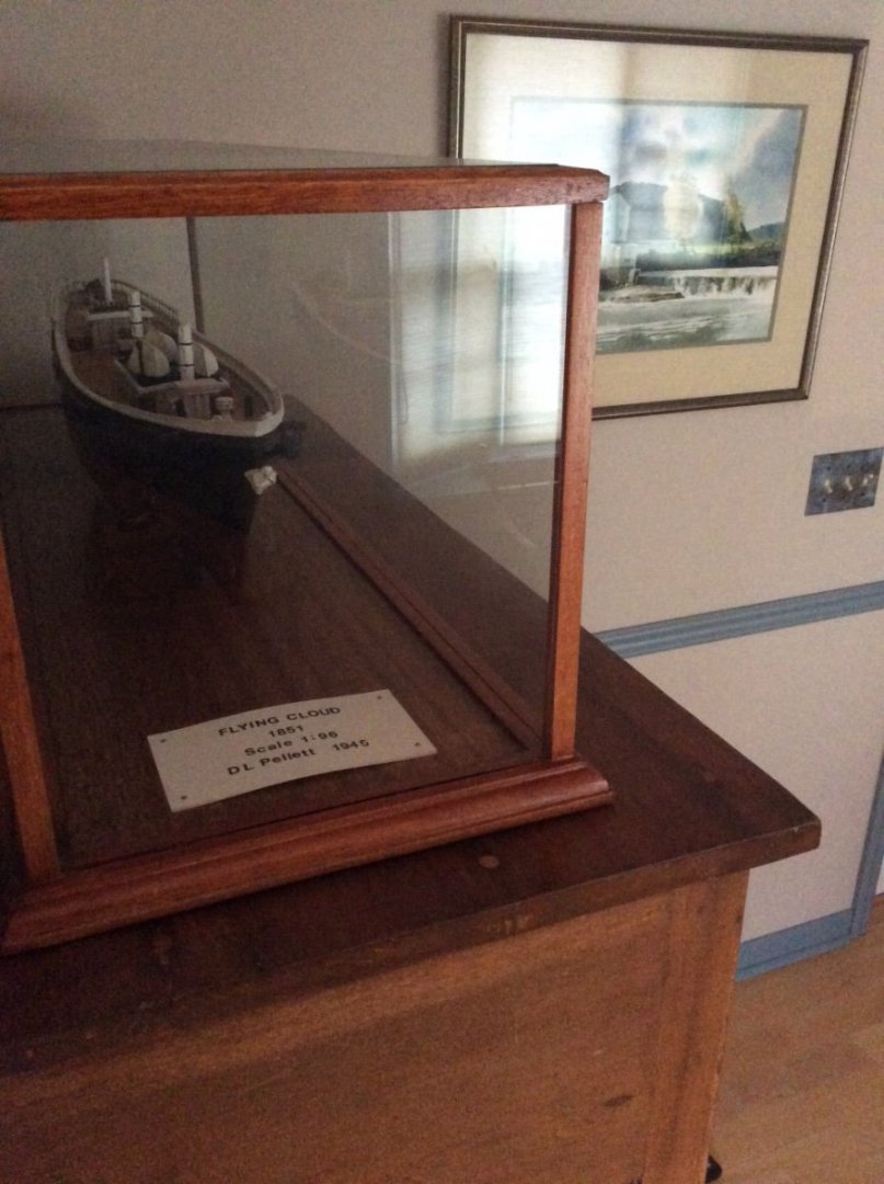
When I saw the model in the last picture that you posted I thought, “Hey, that’s my model!” See rather poor picture below. My model was built from an A.J. Fisher kit by my father in the early 1940’s. He never rigged it and when the war ended went on to other projects. The model that you show, the one without sales appears to be one too. A.J. Fisher was located in Detroit, MI and produced very high quality ship model kits. The fittings (small parts) included in their kits were unequalled in quality. Hulls were solid as Chris points out and allowed a skilled modeler to produce an outstanding model. I doubt if many of the kit models made today will hold up as well as yours over the years. These old kit models probably do not have much financial value. That doesn’t mean that one or perhaps both are not worth restoring. When I got my model after my mother died, it was filthy and damaged by the movers. I gave it a good cleaning (saliva on QTips) reglued loose parts, touched up damaged paint, added the mast stubs, and built the glass case. I treasure this as a tribute to my father’s craftsmanship and hope that my children and granddaughters will also. You will note that the masts on your models are in three sections. The bottom section known as the lower masts. The three lower masts and the rigging attached to them on the model without sails appears to be in good shape. You could clean up the model as I did mine, remove the broken upper masts and rigging and display it in a custom built glass case with just the lower masts and rigging. Roger
-
Flat brass bars
Roger Pellett replied to rich-mar's topic in Metal Work, Soldering and Metal Fittings
A Byrnes saw with a fine toothed blade does an excellent job of cutting brass strip. In some cases it helps to first glue the brass sheet to a piece of thin craft plywood. Ambroid (Duco) cement from our local hardware store works for this. The brass strip can be easily peeled from the wood backing after cutting. Roger -
Wonderful pictures! What a great visit. I think that you made his day too. It is my experience that many museum professionals love talking about things in their collection to interested visitors. I suspect that they are tired of the many visitors who have little knowledge of history and less interest in learning about it. Roger
-
That Bluejacket kit builds a gorgeous model of Olympia!!
-
Schrouds Deadeye’s etc mystery
Roger Pellett replied to Elmina's topic in Masting, rigging and sails
Keep in mind that you’re not replicating rigging for an actual ship. You are restoring an antique. That is why I suggested paying particular attention to attachment points. If I understand your photos there are only two chain plates (attachment points) per mast, per side. Ordinarily I would agree, two shrouds made from one line looped around the mast head secured to the chain plates using the deadeyes from the original rigging. However as the cliche goes, “ it’s complicated!” The model builder included a separate topmast and a spreader. Using your two chain plates would mean one shroud from the mast head to the first chain plate and a second from the topmast head passing over the end of the spreader and down to the second chain plate. See sketch below. Oops! Looking at your photo again, I see that the model builder chose a shortcut. Instead of adding a third chain plate he piggybacked a second deadeye on the forward chain plate to account for the topmast shroud from the spreader. Even though not actual practice I would not add a third chain plate. I would duplicate what the original builder chose to do. Roger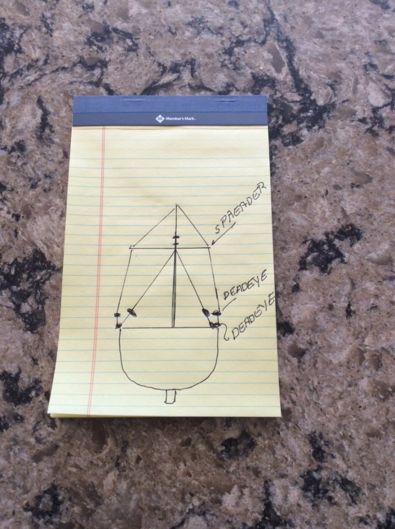
-
In your case, I don’t think that It’s a sin. Several original drawings of Virginia Pilot Boats are available. You can use hull lines from one of these. You can get other details from the painting that you posted. The painting is one of several painted by a serving Royal Navy Officer so is probably accurate. That American Pilot boats had names, and later numbers on their sails is also a documented fact. It pays to advertise! Calling it Mary, Ann, or Jane etc. would be typical for pilot boats of the period. Avoid Tiffany, Lisa, Meadow, etc.😀. Roger
-
Running rigging termination location help
Roger Pellett replied to Peanut6's topic in Masting, rigging and sails
A mystery that I pondered for quite a while during construction of my Longboat model. As we have discussed, these boats were intended to do double duty as rowing and sailing boats. There were times when they were used in actual combat; landing sailors and marines, and “cutting out” of anchored enemy vessels. Murphy is alive and well at sea, and a cleat would be ideal for snagging the leg of a sailor while boarding a hostile vessel on a dark night. I therefore eliminated any belaying points attached to the hull that could not be removed when the boat was not rigged to sail. Belaying pins are removable. I restricted cleats to those attached to spars. As a small boat sailor, I was taught to never belay a sheet (for obvious reasons). Old seamanship books stress this point repeatedly too. Nothing very specific, but points to consider. Roger -
For chronic heartburn sufferers like me the “acid blocking” pills have been revolutionary. Here in the USA these pills go by the names Prilosec, Nexium, etc. Originally requiring a Doctor’s prescription they are now available here in the US without one. Check with your chemist. Roger
-
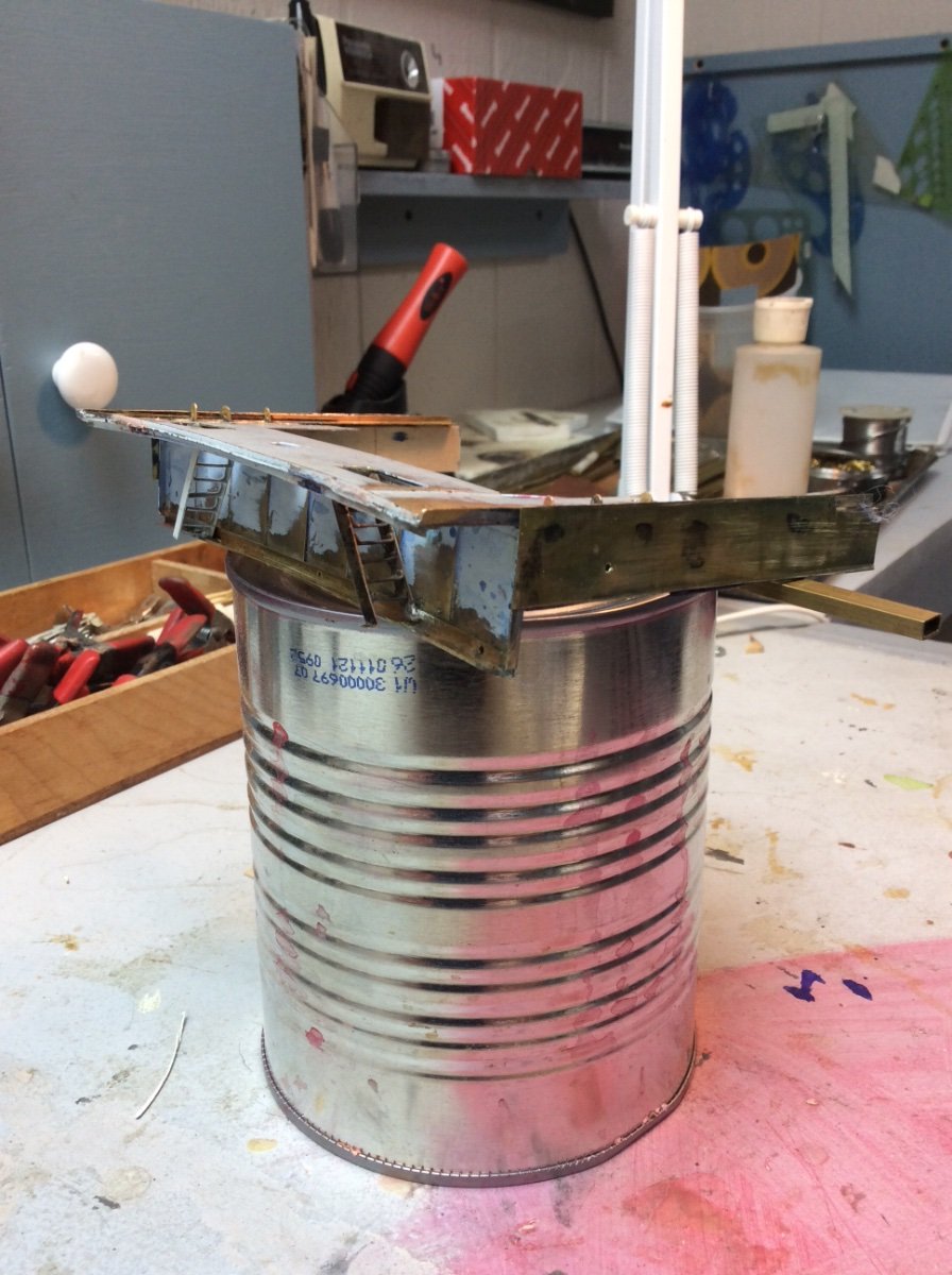
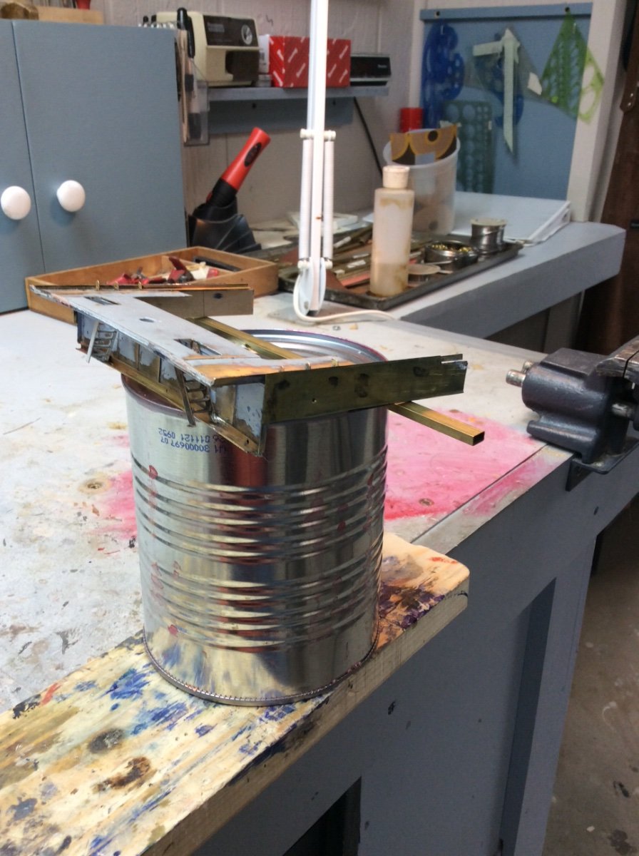
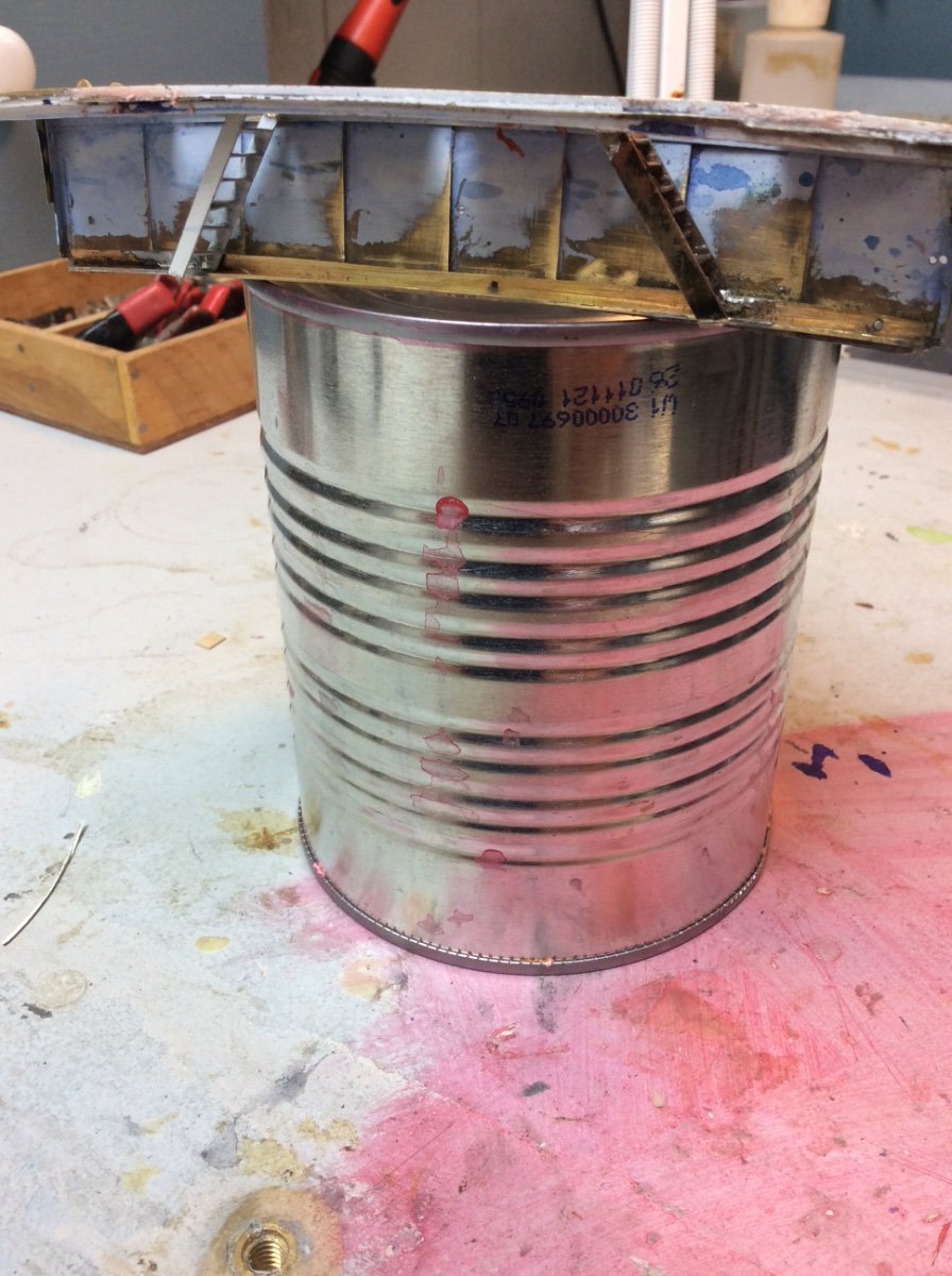
Well, three months plus since my last post and progress has been slow. The month of March was spent in Florida and the first half of April was spent catching up with all of the daily chores that didn’t get done in March. On April 19 I had surgery to correct drooping eyebrows and eye lids. This used up a week of time recovering that could have been spent in my shop. The surgery has healed well and the stitches are gone. Work on the model has involved construction of the aft bulkhead subassembly. This forms the forward end of the poop deck and will be fitted to the poop deck assembly later. There is a cottage industry writing death and destruction books about Great Lakes Shipwrecks. The market appears to be summer tourists. Nothing delights the authors of these books more than to emphasize the mystery surrounding all of the vessels that have disappeared through a “crack in the Lake” and Benjamin Noble has not been exempt from this sensationalism. These same authors like to point out that she was unique as her after deckhouse sat atop a raised poop deck. These writers fail to understand that she was originally built to carry a deckload of pulpwood logs and that the poop deck bulkhead confined the deckload. The entire assembly was built from soldered brass. The ladders were built by capturing brass strips to be soldered in a homemade aluminum ladder jig. The padeyes sticking up through the deck edge angle on each side will secure the shrouds from the mainmast. To avoid a disaster when rigging the model, each padeye is L shaped with the horizontal side of the L soldered to the underside of the deck plating.