Roger Pellett
-
Posts
4,519 -
Joined
-
Last visited
Content Type
Profiles
Forums
Gallery
Events
Everything posted by Roger Pellett
-
Was Howard I. Chapelle Controversial
Roger Pellett replied to SaltyNinja's topic in Nautical/Naval History
Chapelle also documented and drew plans for the lateen rigged fishing boats built by Italian immigrants. These used to used to sail from San Francisco. -
Brass Blackening questions
Roger Pellett replied to stevenmh's topic in Metal Work, Soldering and Metal Fittings
Testor’s Dulcote! I have been recently been painting cast metal model soldiers. As painted with acrylic paints the surface is dead flat and the paint is easily rubbed off. Dulcote is a matte spray lacquer. A quick shot of Dulcote makes a remarkable difference. I also spray it over blackened brass. The finish is also much more durable. I like Dulcote much better than the hardware store clear matte spray. Roger -
Wood Filler
Roger Pellett replied to Randy1962's topic in Building, Framing, Planking and plating a ships hull and deck
Change your plan and stain the model! One of the wood dyes is more likely to penetrate the repaired area. -
Was Howard I. Chapelle Controversial
Roger Pellett replied to SaltyNinja's topic in Nautical/Naval History
Several somewhat unconnected thoughts: There is no American maritime history researcher that even comes close to Chapelle. He spearheaded the documentation of local American Sailing craft large and small. He realized and followed up on the fact that the Royal Navy had in its archives dozens of drawings for captured American sailing ships. He was an excellent draftsman and produced hundreds of drawings. Even with his interpretations and reconstructions models built from these drawings are more accurate than 90% of those built from mass market European POB kits. And, regarding USF Constellation he was 100% right! I would not consider him to have been uneducated. While he was not a graduate of one of the “Big Three” Naval Architecture Programs (MIT, University of Michigan or Webb Institute) and might not have been qualified to design the SS United States, I believe that he had completed the Westlawn Correspondence Naval Architecture Course. His writings indicate clearly that he understood sailing vessel design; a subject not taught at the University of Michigan when I was a student there in the1960’s. Sailing yacht design was considered to be an art, not a science. Any Naval Architect will tell you that the basis for any ship design, full size or model is an accurate set of hull lines. Chapelle’s drawings were based on old drawings or half models, so he often had to correct for distortion in his source materials. Furthermore, no two Naval Architects will produce exactly the same lines drawing from the same input data. This happens because of “fairing.” In plotting curves, there will always be points that don’t line up or don’t match in all three dimensions. The drafter must, therefore, adjust his drawing to produce a fair surface and no two drafters will do this the same way 100% of the time. How many different “original” lines drawings exist for the Yacht America and which on reflects the actual vessel. L. Francis Herreshoff was not particularly well educated in the traditional sense. He was Dyslexic and his father, MIT educated Nathaniel Herreshoff, sent him to a local Agricultural School with the idea that he would manage a farm that the family owned. Instead of completing the program he effectively ran away from home and got a job as a draftsman with W. Starling Burgess. He learned yacht design on the job. In fact Nathaniel Herreshoff was not a Naval Architect. His degree from MIT was in mechanical engineering. Olin Stevens also was not a University educated Naval Architect and has written that late in his career had trouble understanding the new CFD (Computational Fluid Dynamics ). Roger- 17 replies
-
- 11
-

-

-
My father-in-law spent the war years as a US Navy Supply Corps Officer. Most of the time spent at a landing craft repair base on Florida Island in the Solomon’s. When the war ended he was transferred to the Charleston Naval Shipyard. The guy that he relieved couldn’t account for 500 gallons of gasoline and of course everyone wanted to go home. My father-in-law was a stickler for details. 50 years after the war he was still complaining about the guy and the gasoline.
- 126 replies
-
- 7
-
-

-
- Thetis Bay
- Finished
- (and 4 more)
-
Very nice work! Given the ability of the World War II US aircraft industry to mass produce aircraft, I’m surprised that the Navy expended the effort to ship these planes back home.
- 126 replies
-
- 7
-
-
- Thetis Bay
- Finished
- (and 4 more)
-
I always look forward to your progress on this old girl! Nice work
- 740 replies
-
- 3
-
-
-
- Tudor
- restoration
- (and 4 more)
-
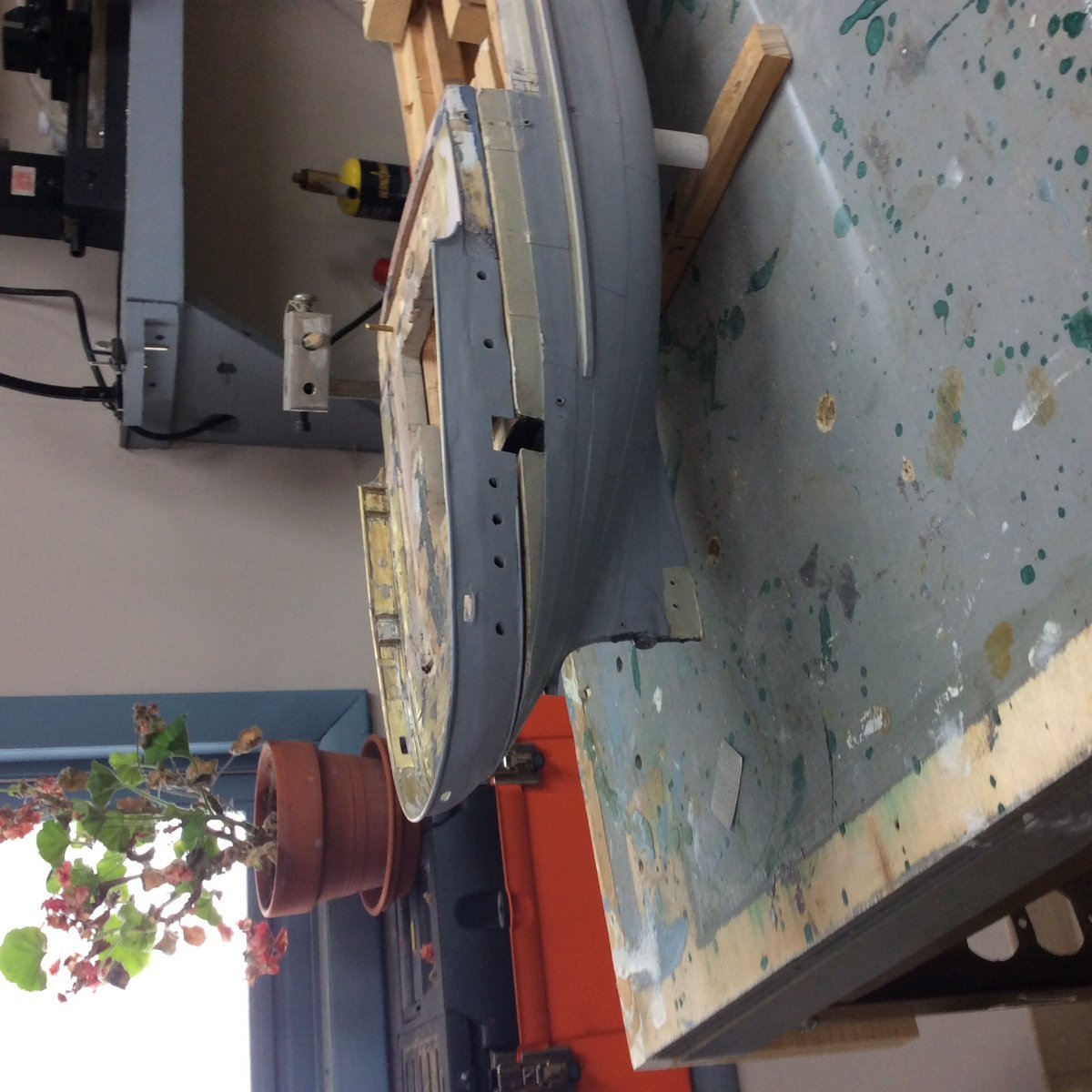
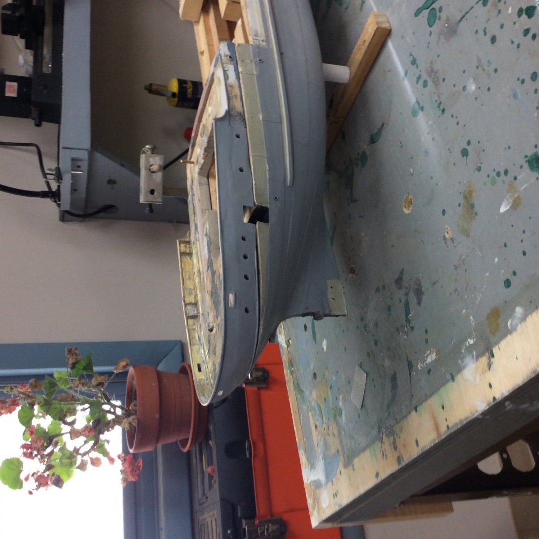
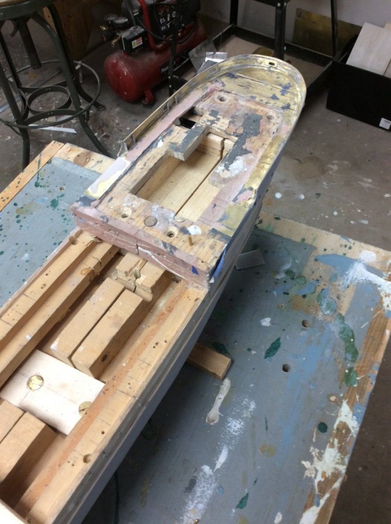
The poop deck itself was simple enough, a block of wood carved to shape. A disc sander was helpful. The trim piece is a piece of brass sheet fastened to the bottom of the deck piece and will eventually be sandwiched between the deck and the poop deck. The bulwark was made from .005in brass sheet formed around a wooden former. Tabs on the bottom of the bulwark allowed it to be soldered to the bottom of a brass deck piece. The round cap was a piece of 1/16in brass tubing, slotted with a fine toothed blade on my Byrnes Saw. I decided to cut the three openings in The bulwark after I had formed, soldered, and cleaned it up. When I tried to scribe one of the roller chock ports, Disaster! The scriber tore the thin brass. I fixed things by cutting a “doubler plate” from .01in brass. I cut the correct opening into the doubler and soldered it to the inboard side of the bulwark. In addition to reinforcing the opening it also served as a guide for filing the opening, and a backup for the Bondo (a necessary modeling material) used to repair the damage. Use of doubler plates reflects actual shipbuilding practice. In Retrospect I should have made the bulwark from .01in brass to begin with. Here are the results. I still have some cleaning up to do of the brass decking.
-
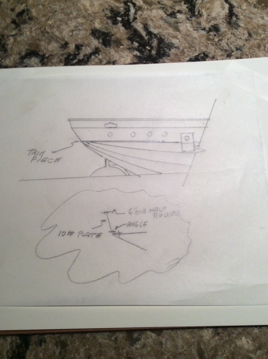
Well, it’s way past time to post some progress but I have been busy working on the Benjamin Noble. I decided to tackle construction of a subassembly that I was not looking forward to; The poop deck. The Noble was unusual but not unique among Lake Freighters as she had a raised poop deck. This deck formed the after end of the “box” for hauling a deck cargo of pulpwood. It is a complex structure consisting of: The deck itself A curved bulwark. The bulwark is pierced with three openings, an oval opening in the center of the stern for a towing cable, and an opening on each quarter for a mooring cable. On the real ship the bulwark was constructed from 10# (1/4in) plate. The top of the bulwark is capped with a 6in diameter rail, the bottom is secured to the deck with an angle. Neither the General Arrangement nor the structural drawing shows support brackets for the bulwark. I do not believe that this is an omission as these support brackets are clearly shown for the main deck bulwarks. There are a pair of brackets reinforcing the oval towing port at the center of the stern. There are also four arches per side that rise above the bulwarks and bend over to the top of the deck house. Apparently the designers considered these to be sufficient. A sketch of the poop deck, bulwark and stern. There is a transition where the plating running diagonally up the hull meets the fore and aft plating on the side of the poop deck. This transition was covered with a half round trim piece, accented with a paint color different from the hull.

-
Looking for a good "starter" pin vise set
Roger Pellett replied to Capella's topic in Modeling tools and Workshop Equipment
There is a lengthy series of posts under the name Pin Vice Help Needed. You can find it with the search function above. I bought a 4 pin vice set made by Moody in Providence, RI. Good quality. -
Masts and the use of power tools
Roger Pellett replied to DaveBaxt's topic in Masting, rigging and sails
I used the table saw trick for my scratch built longboat model. As best that I could determine from the Admiralty drawing, the mast had a straight taper. I understand that masts for ships as opposed to boats did not have a straight taper. Roger -
Kevin, That’s right, one rudder, with two fixed offset parts. I don’t know when or if they stopped using them; my Naval Architecture education occurred in the first half of the 1960’s and they were still being fitted to new ships. Finite element modeling, CAD, and powerful PC’s have allowed Naval Architects to analyze complex fluid flow problems that could not be solved in the 1960’s. I would, therefore, believe that this has improved efficiency of propellers. It may seem counter intuitive but propulsion efficiency is better for single screw than twin screw ships as the single propeller works in an area where it can capture more energy from turbulent water shed from the hull. This “extra boost is called the Wake Fraction. Roger
-
Masts and the use of power tools
Roger Pellett replied to DaveBaxt's topic in Masting, rigging and sails
An easy way to make straight tapered masts. This assumes that you have table saw. 1. Rig up a simple taper jig. This is nothing more than a strip of wood that fits into the saw’s miter gauge slot fastened to a board. 2. Tack glue a mast blank to the jig so that it passes through the blade with the correct taper. Rip the blank. Rotate the blank 90 degrees, glue to the jig and rip again. You now have a tapered mast blank. 3. A second jig: two pieces of wood with one edge of each chamfered. Fasten the boards together edge to edge with the chamfers forming a Vee groove. 4. Lay the tapered blank in the Vee groove and plane each corner the same number of strokes. 5. Clamp an electric drill in a vice, chuck the mast blank and turn on the drill at slow speed. Carefully sand the octagonal plank round. It’s easier than it sounds. Roger -
Kevin, That’s called a ContraGuide rudder. It is shaped that way to straighten flow from the propeller. The propeller works by accelerating a column of water behind the ship. The reaction to this column of water, Newton’s Third Law, is a force in the opposite direction that pushes the ship ahead. Water, however, is viscous and this viscosity causes the water in the column from the propeller to rotate. This rotation is lost energy. The offsets on the rudder are intended to introduce a vector opposite to that of the rotating water column, to recover the lost energy. Roger
-
Looks great!!!
-
If you have room for them, my advice would be to outfit yourself with full sized woodworking tools, both hand and power and learn how to use them. You can then move into small modelmaking tools as the need arises. The one skill that you need to master is keeping your edged tools sharp. Find a good book on sharpening and read it. When I have a chance later today I’ll post information on an excellent book on the subject. Roger
-
Old Montgomery Ward Model Kit worth building?
Roger Pellett replied to kwaheltrut's topic in Wood ship model kits
It depends on what you want to accomplish. From the drawings, it is not going to result in anything that resembles a real ship. -
Joseph, It’s coming along nicely. It’s a minor detail but the hawse holes in the original gunboat displayed in the Smithsonian are lined with lead. The linings are grey, not black.
-
Jared, A suggestion for your open boats- Use The Kit supplied cast boat as a form and vacuum form a new one. Vacuum forming is easily done with ordinary household stuff. A shop vacuum or even a canister type household vacuum provides the vacuum. At 1:96 scale, 1in planking is only about .01in thick so the thickness of the shell of the kit supplied boat is way over scale. Roger
- 602 replies
-
- 3
-
-
- Flying Fish
- Model Shipways
- (and 2 more)
-
Patience and Perseverance: it’s nice to have both, but if you don’t have patience, you better have perseverance! Roger
-
A recent WoodenBoat magazine article had a recent feature article about a present day reimagined model yacht class that is popular in the Pacific Northwest. Interesting stuff.
-
I don’t believe that it is exaggerating to say that MSW is the World’s finest storehouse of information about researching and constructing quality ship models. Unfortunately many questions are so indefinite that they fail to take advantage of this expertise. For example, a question like “I am building XYZ, what glue should I use?” Is to indefinite for an intelligent response. What is the specific application, what materials are you joining, and where do you live? The answer all depends on the answer to these questions. If you are building the model in Europe, glues available at a US Big Box store may not be available where you live. Other questions require some knowledge of your work environment. Are you building the model in an apartment? Do you have access to major woodworking or metalworking tools. For example, if your model is finished, you are building a case and you live in apartment, an answer explaining how to build a wood framed case using a table saw is probably not helpful. In short, more specific questions will generate better answers. Roger
-
- 8
-
-
Model Railroad “S” scale is 1/64. The old American Flyer electric trains were S scale and still have a devoted following. Check specialty model railroad suppliers.
-
Are you sure that Puritan had a windlass? These yachts were sailed by large professional crews capable of rigging multipart tackles to lift an anchor. They also had powered tenders to tow them to and from the starting line. Puritan was designed specifically to defend the cup so had little need to anchor. Weight in the ends of a racing yacht is bad as it increases pitching. Edward Burgess would have known this and would not have burdened her with unnecessary topside weights. The Herreshoff Museum and America’s Cup Hall of Fame in Bristol, RI has models of America’s Cup defenders. Give them a call. Roger
-
Billowing sails on Vasa? An Oxymoron!! She was incapable of carrying her rig in much more than a deal calm. Roger