HOLIDAY DONATION DRIVE - SUPPORT MSW - DO YOUR PART TO KEEP THIS GREAT FORUM GOING! (Only 13 donations so far - C'mon guys!)
×


G.L.
-
Posts
1,553 -
Joined
-
Last visited
Content Type
Profiles
Forums
Gallery
Events
Everything posted by G.L.
-
 Thank you for the compliment, Chad. For the question 'what's next': I still have a project running: Oostends schipje (Ostend shrimper) by G.L. - scale 1:20, building first POF Edition 2 My log on that went a more or less to dormant mode, I urgently need to inject some life into it. Although the next step is making sails and I wait until winter to do that because than it is mostly too cold in my workshop to work there. Sail making has to be done in house where it is warm and I have my wife available to introduce me into the wonderful world of the sewing machine. Last week a started a log on a new project, also a cross section: Cross section Fishing Smack by G.L. - Scale 1/20, POF, approx. 1920. It is my goal to update this log every Sunday.
 -
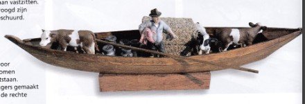
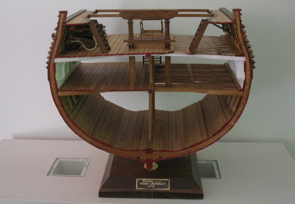
Hello Marcus, I went to the library this morning and searched for the article. It was published in the 'Modelbouwer' 5 of 2017. Like Jan is mentioning, a punter (in this case a Giethoornse punter) is a small open vessel without a deck or a supper structure. It can be sailed. I add a picture of the model which is described in the article. If you wish I can scan the article and mail it to you as a PDF file (I don't know if Dutch is a problem for you). G.L.
-
Jan, I think that last year or in 2016 the Dutch Modelers magazine 'de Modelbouwer' published an article about the build of a punter model. I will check it out next time when I go to the library. G.L.
-
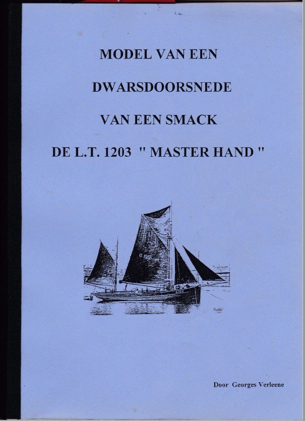
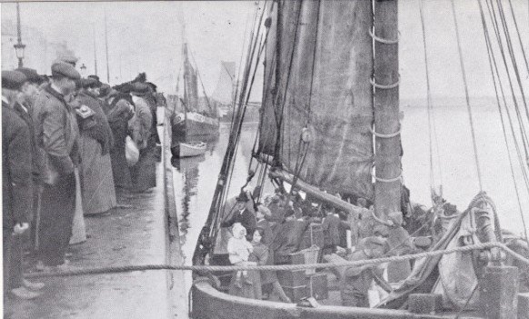
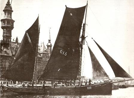
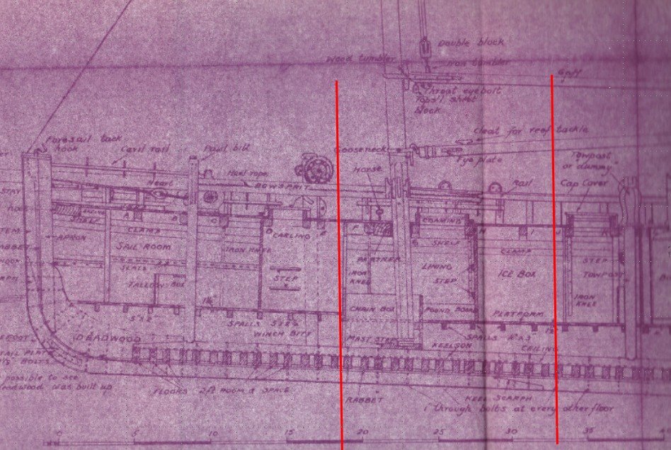
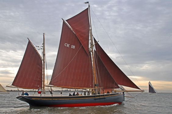
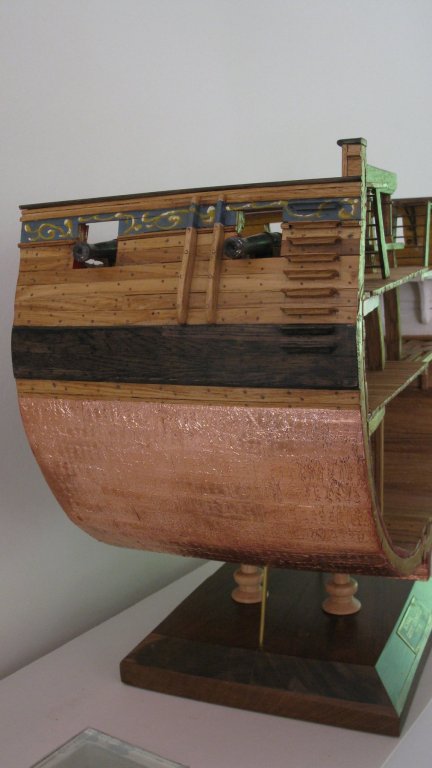
Why building a smack? At the start of WW 1 a lot of Belgian fishermen evaded to England with their vessel. Below a picture of the exodus from Ostend in October 1914. During the war they became familiar with the English smacks which were larger than the Ostend two-mast sloops. Some of them returned to Belgium with a smack. The structure of a smack was more slim of that of a Belgian sloop. After the example of the English smack, Belgian shipyards started to build smacks as well. But Belgian ship carpenters were so used to build sturdy sloops that their smacks were always heavier and wider than the English smacks. Belgian smacks were faster than the Belgian two-mast sloops, but they remained always slower than the English smacks. In general Belgian fishermen had more confidence in the robust Belgian built vessels than in the English ones which they called scornful 'yachts'. Despite several Belgian ship owners ordered their vessel in Brixham, Lowestoft or Fleetwood. So in the twenties of previous century smacks became very common in the port of Ostend, Belgium's principal fishery harbor of that time. My cross section will be an imaginary smack. Based on the measurements made in 1945 by Mr. Edgar March for his book 'Sailing trawlers' of the Lowestoft smack 'Master Hand' and mixed with Belgian shipbuilding elements as provided in the monograph of Mr. Georges Verleene. The handout is meant to build the cross section to scale 1/30, but I will build to scale 1/20. I like it a bit bigger. The 'Master Hand' was 24 m long and 7 m wide. The cross section covers the hull between frame 36 and frame 49, including the foremast. Picture of an authentically restored fishing smack of the Lowestoft fishing fleet: Excelcior.
- 219 replies
-
- 17
-

-
- smack
- cross-section
- (and 2 more)
-
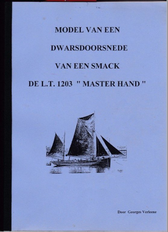
Part 1: Introduction of a new project: With my Triton cross section running to its completion, it is time to look out to a new cross section project. My eye fell on a former group project of our modeling club ( https://dedissel.weebly.com/ a cross section of a Lowestoft smack, based on drawings of the smack 'Master Hand'. One of the club members, Georges Verleene, an experienced ship carpenter (now retired), wrote for this project a very detailed monograph with lots of detailed drawings. The group project went on many years ago, but lucky for me Georges had still a copy of the handout left. 001.pdf
- 219 replies
-
- 2
-
-
- smack
- cross-section
- (and 2 more)
-
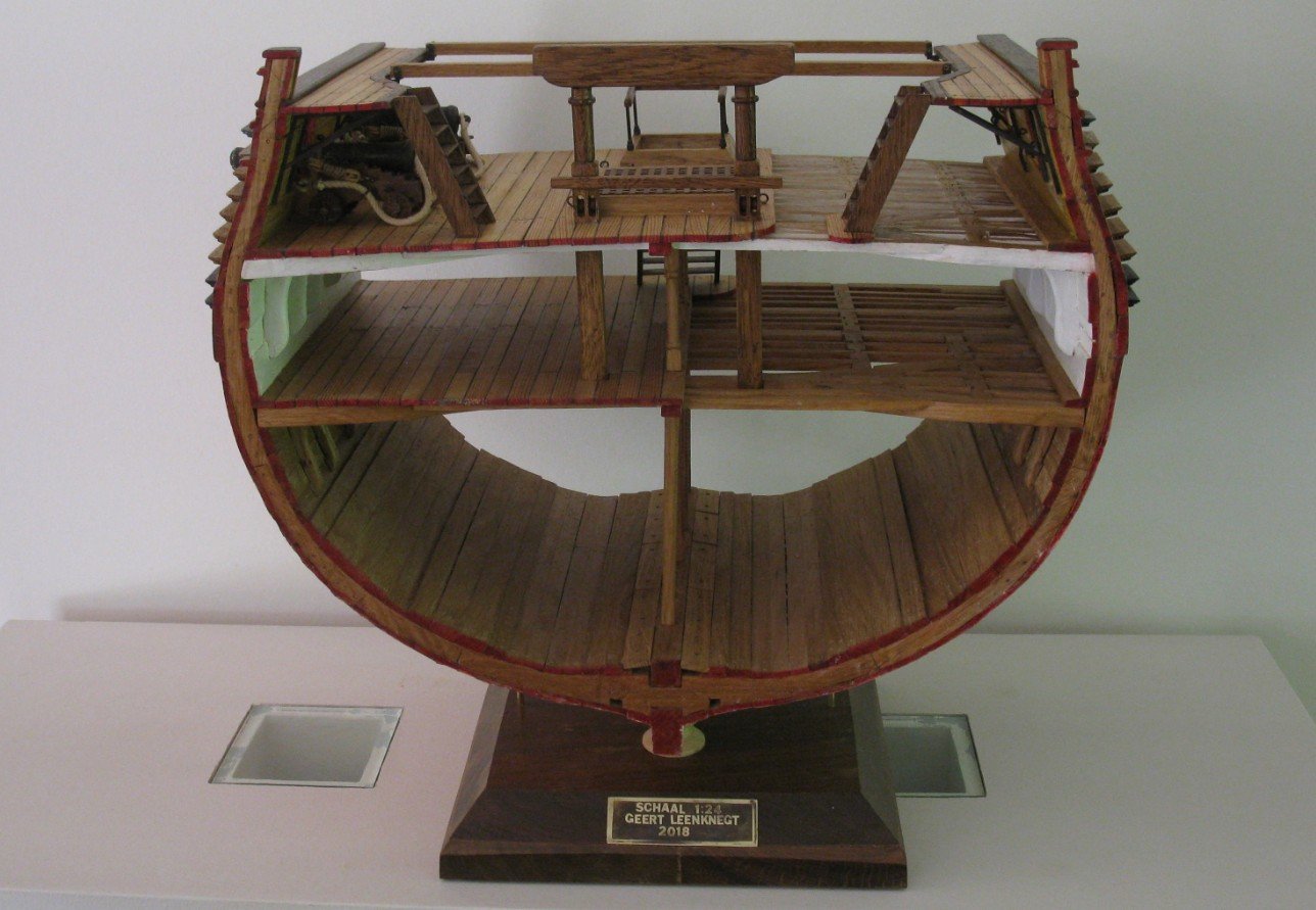
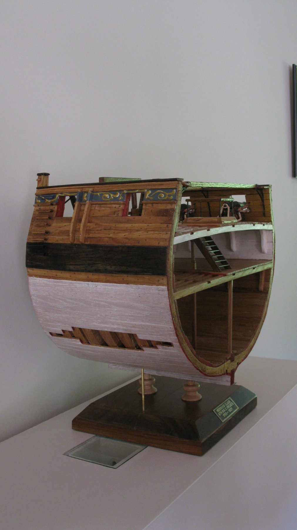
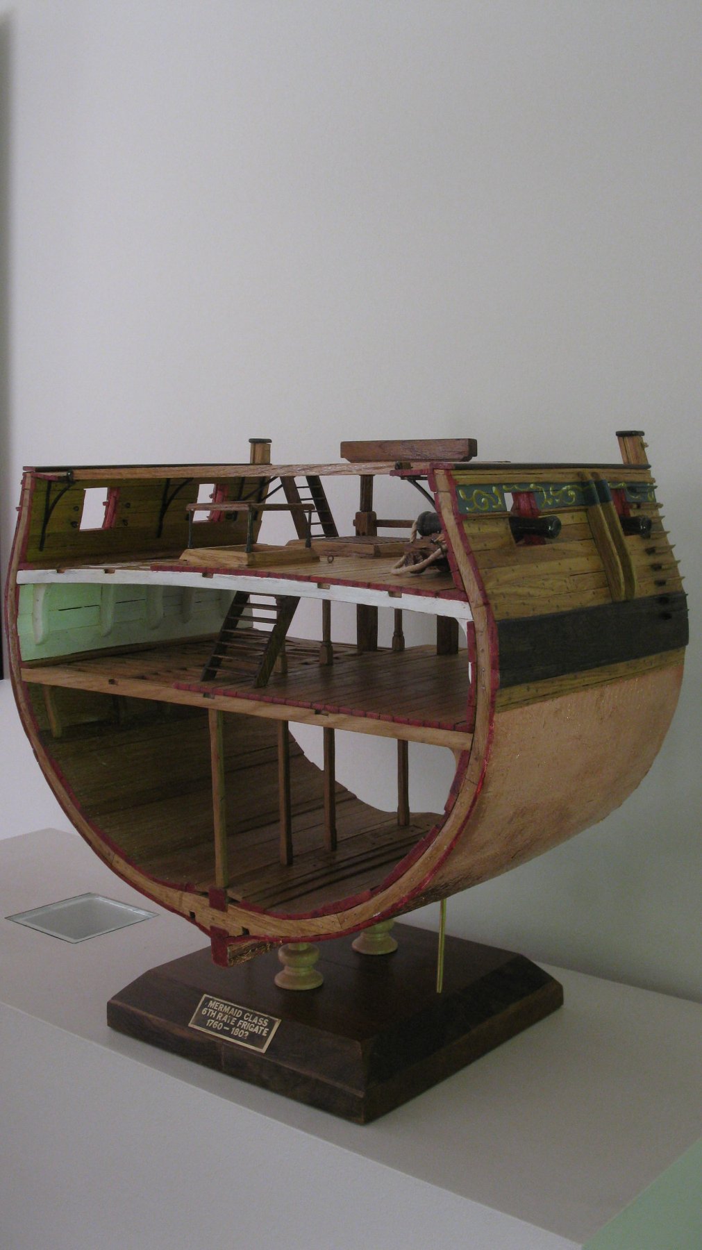
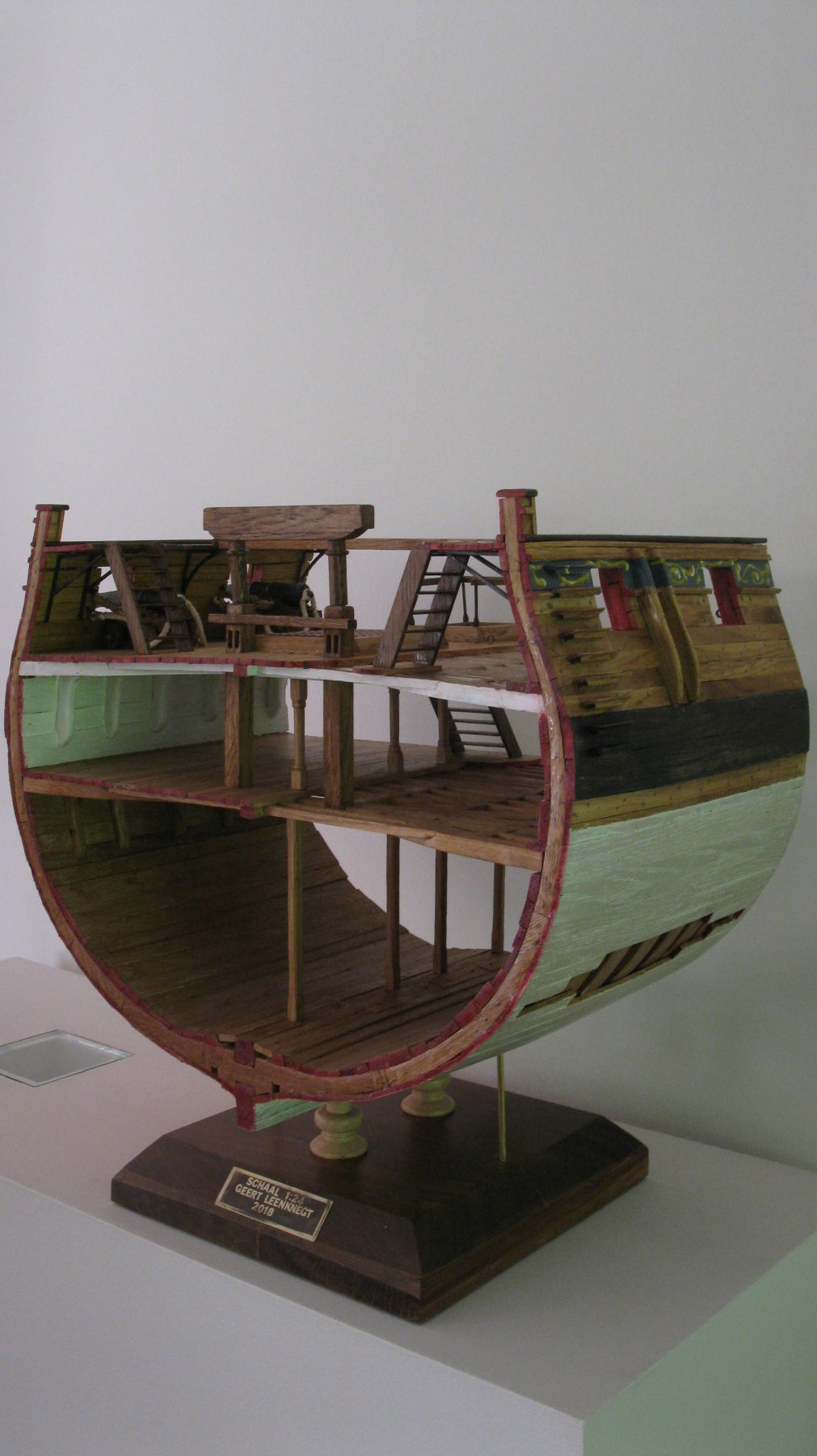
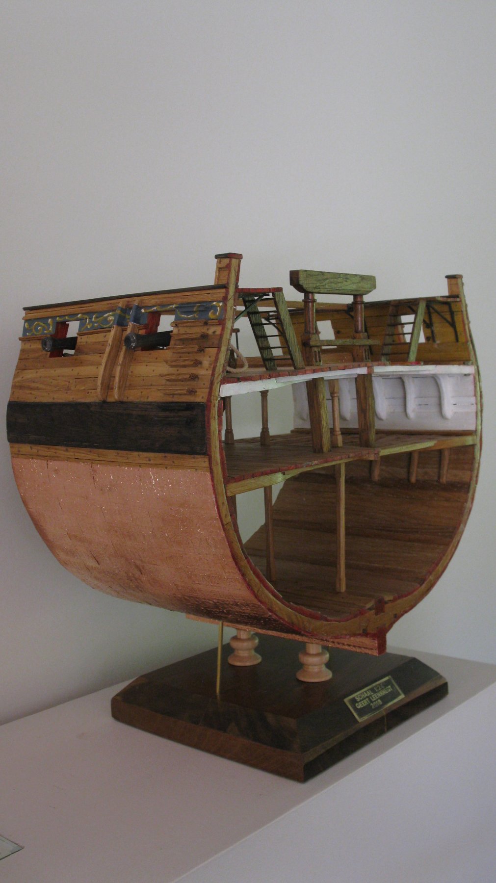
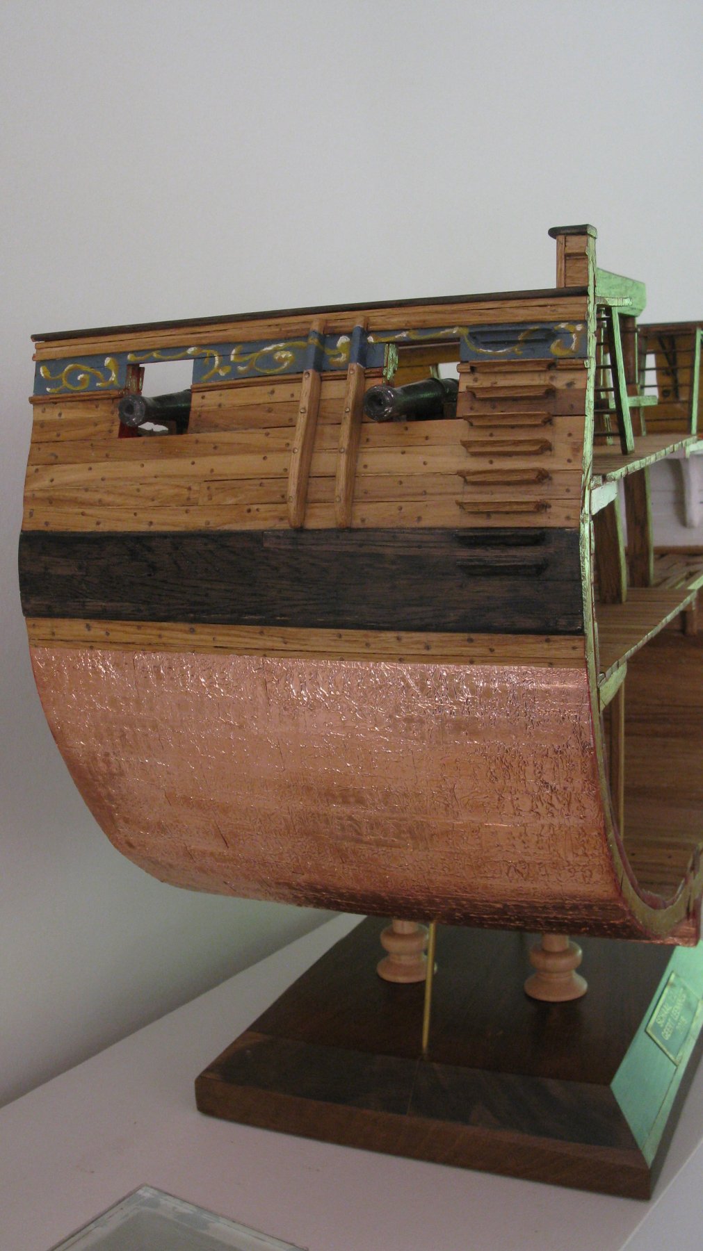
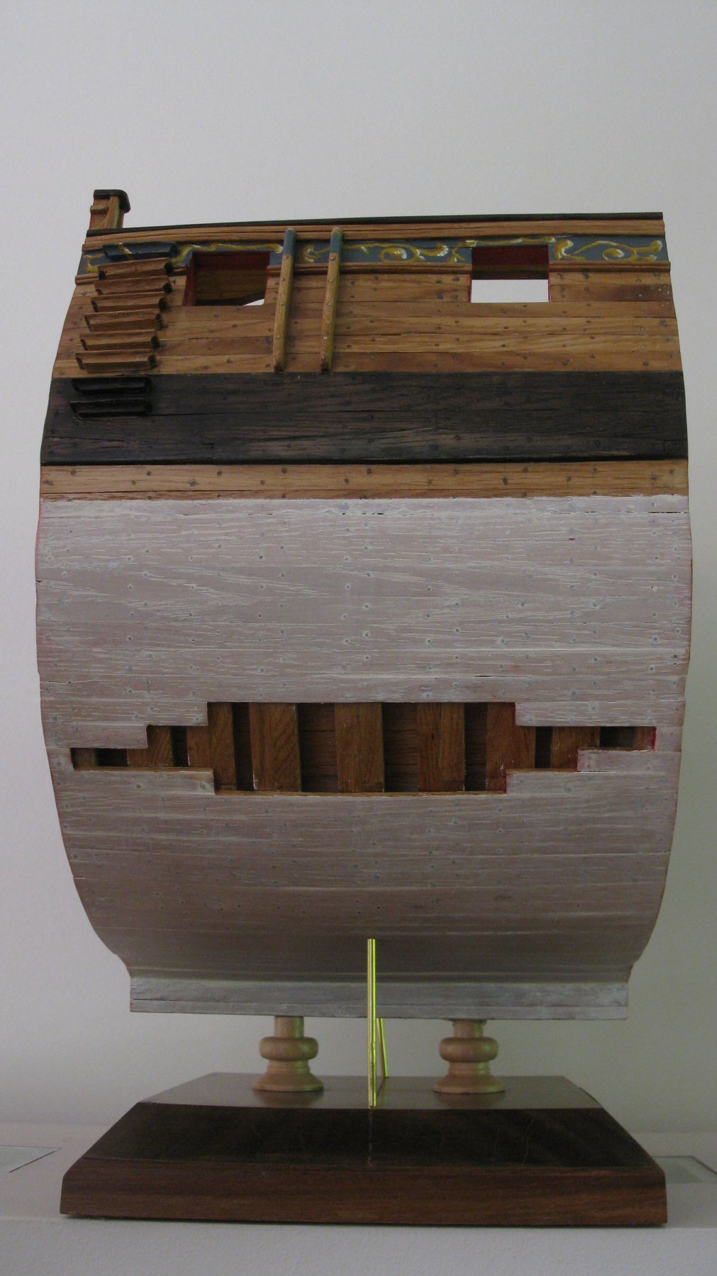
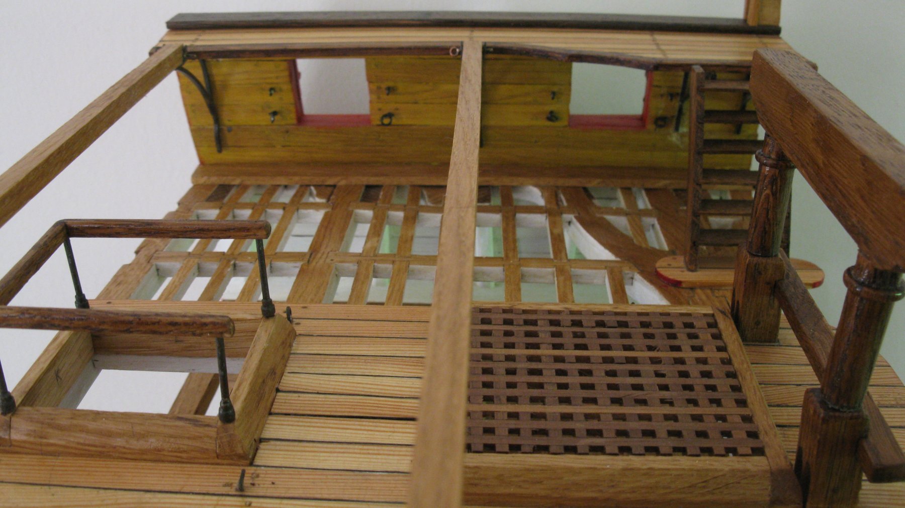
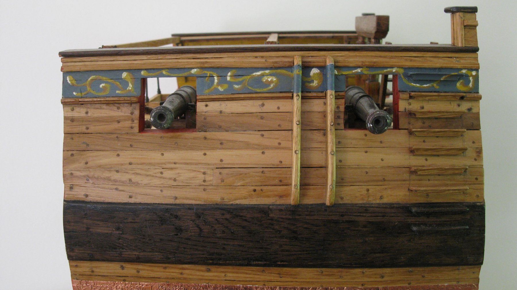
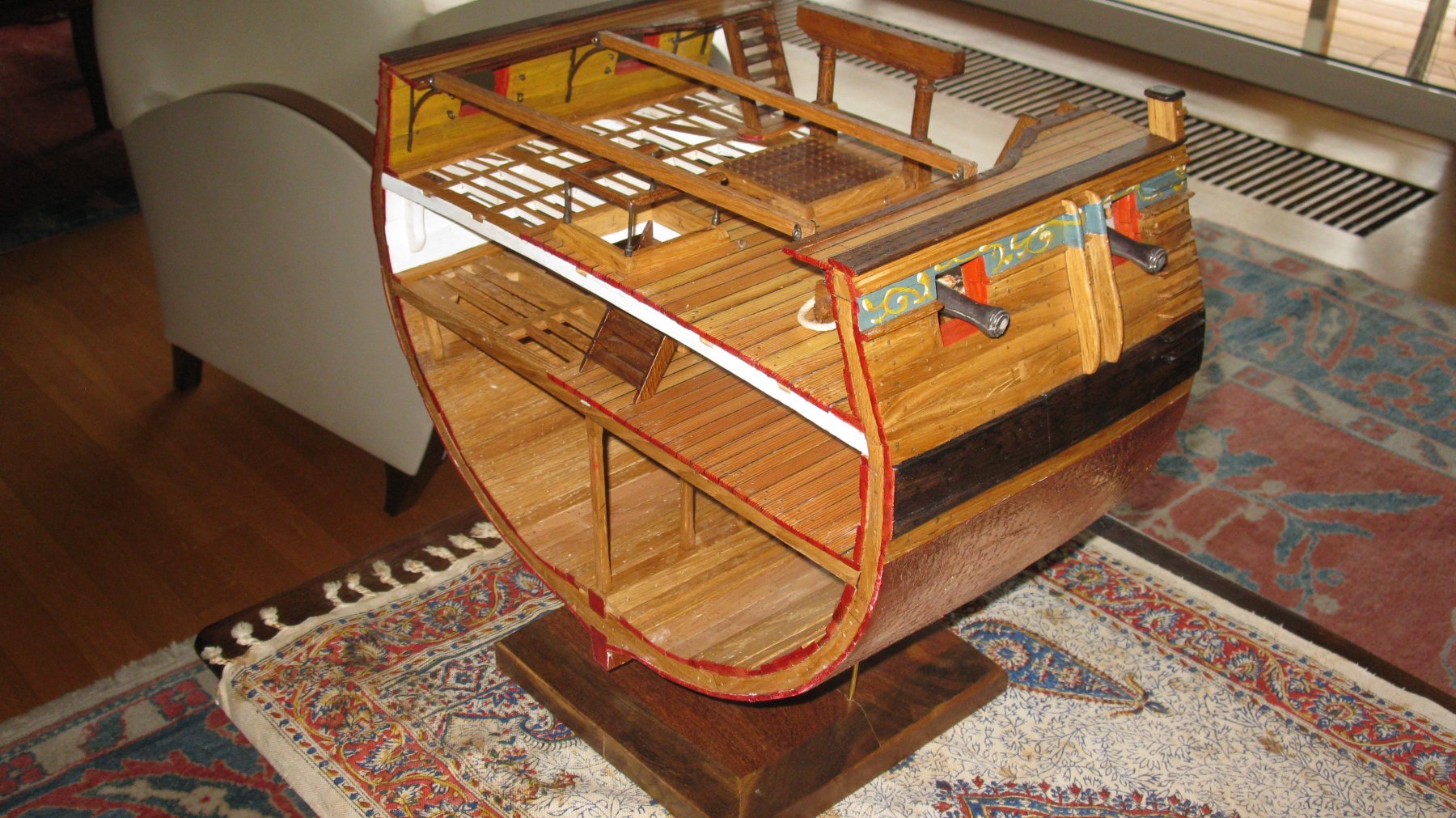
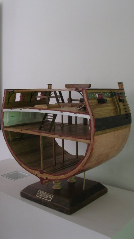
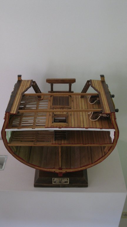
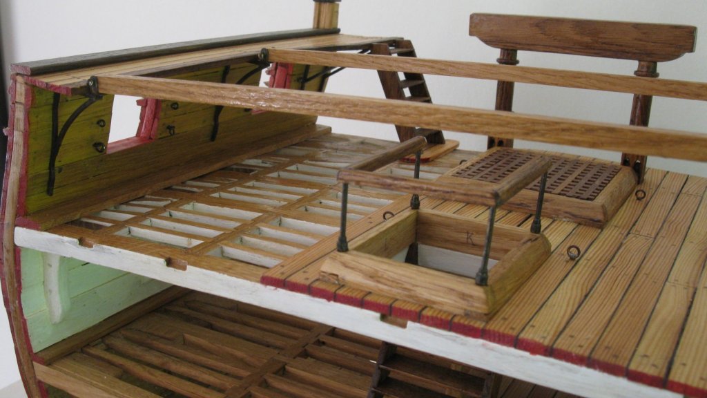
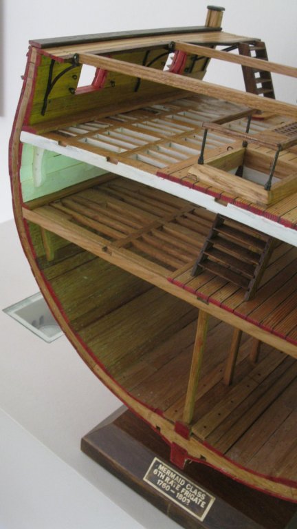
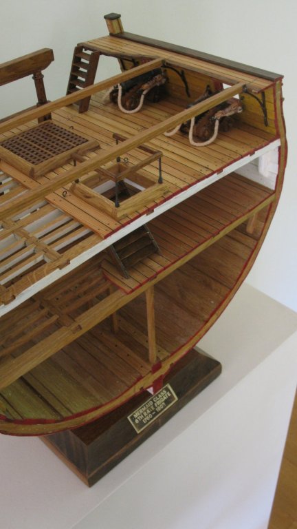
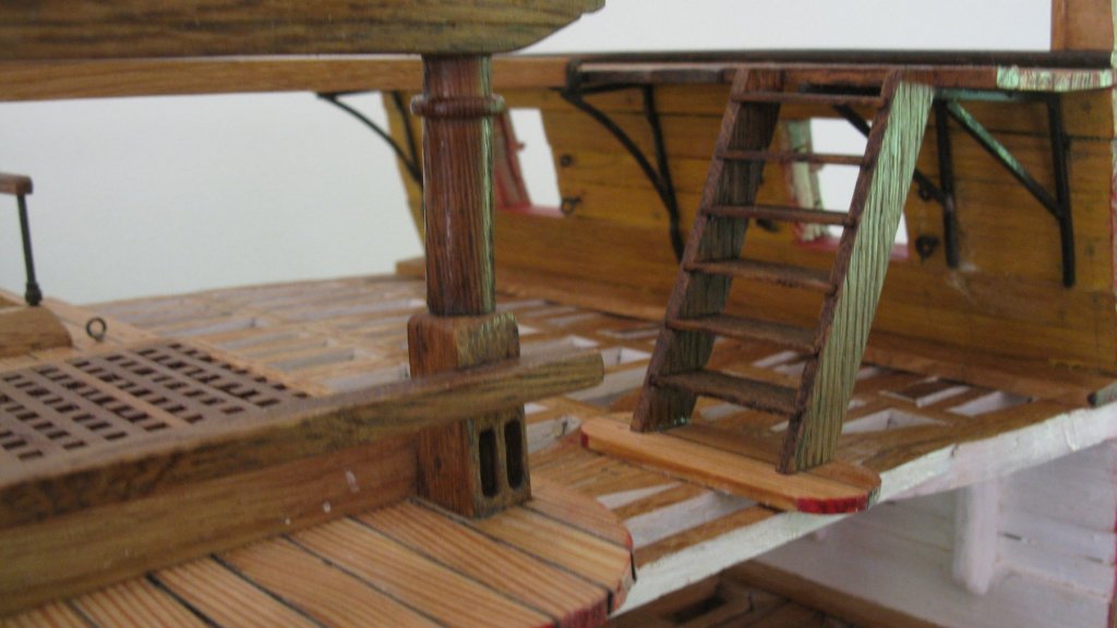
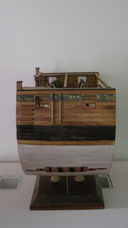
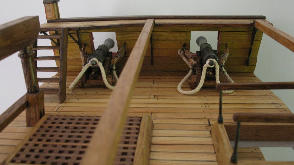
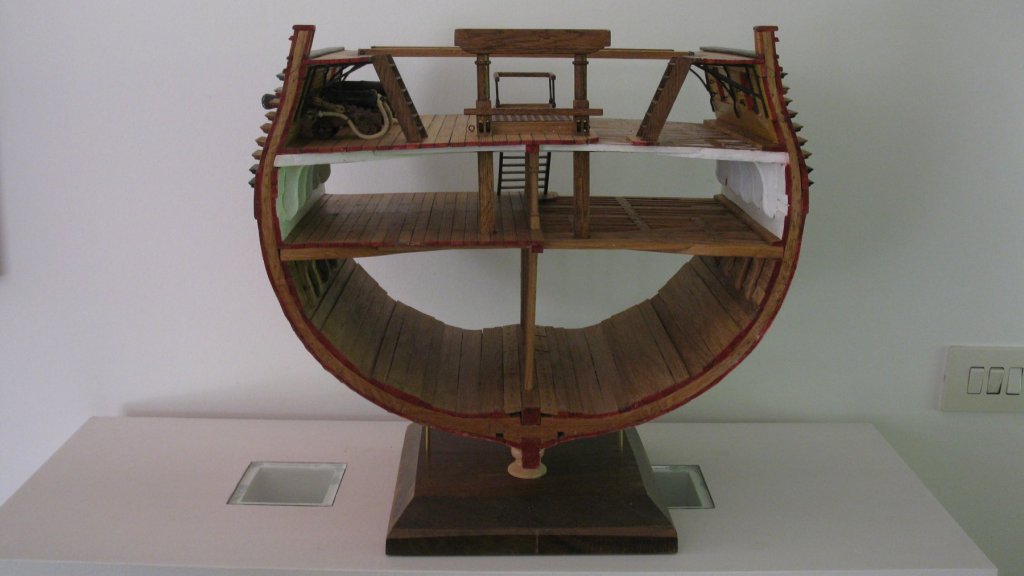
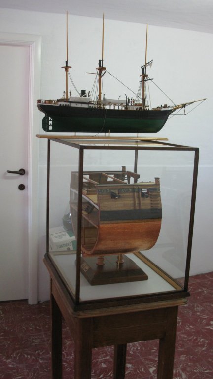
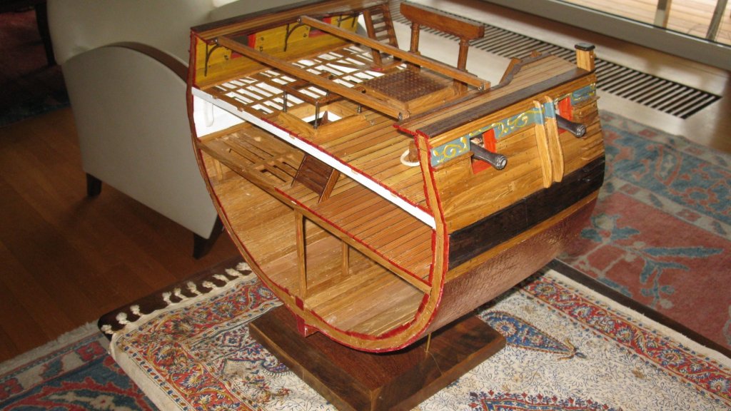
Thankyou Pete, Now some pictures of the completed cross section.


-
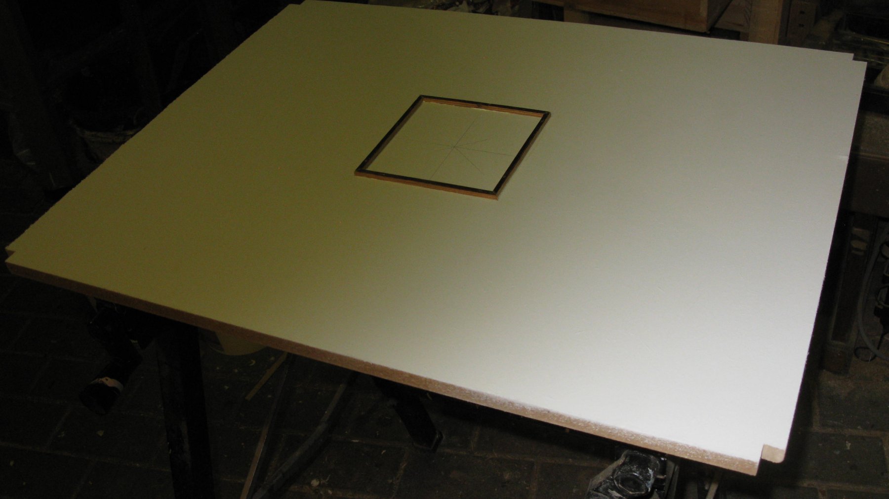
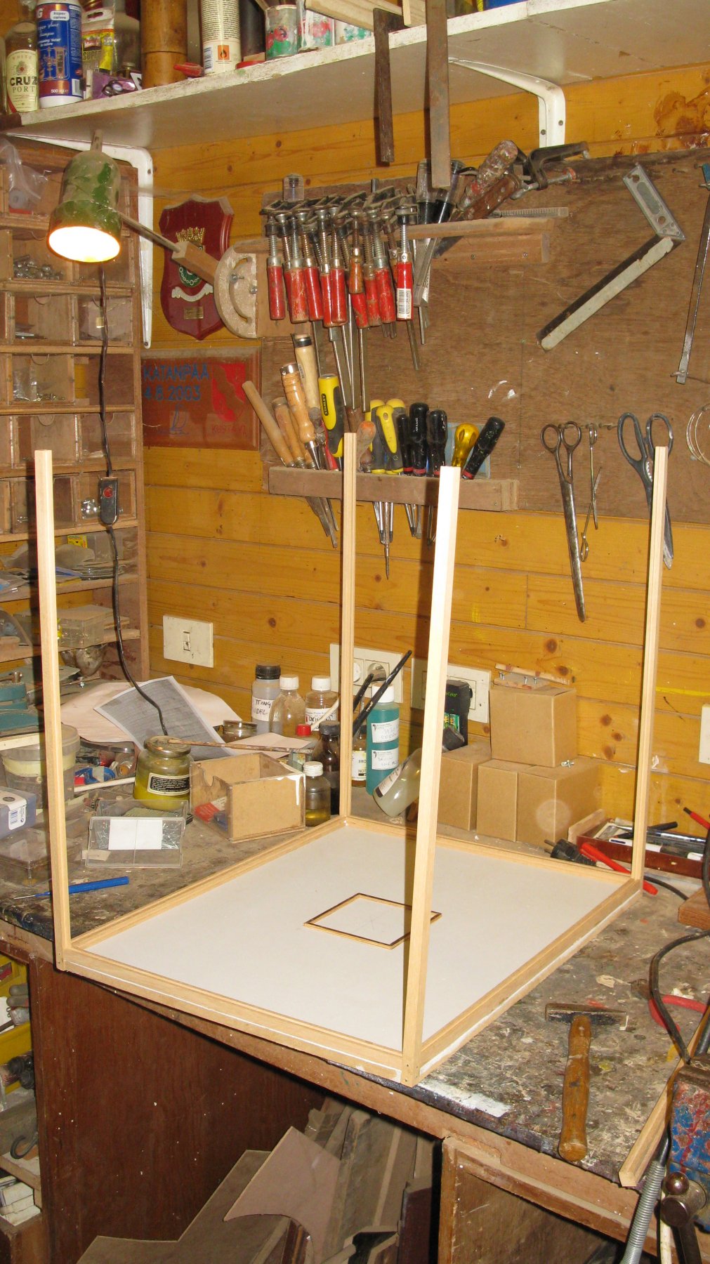
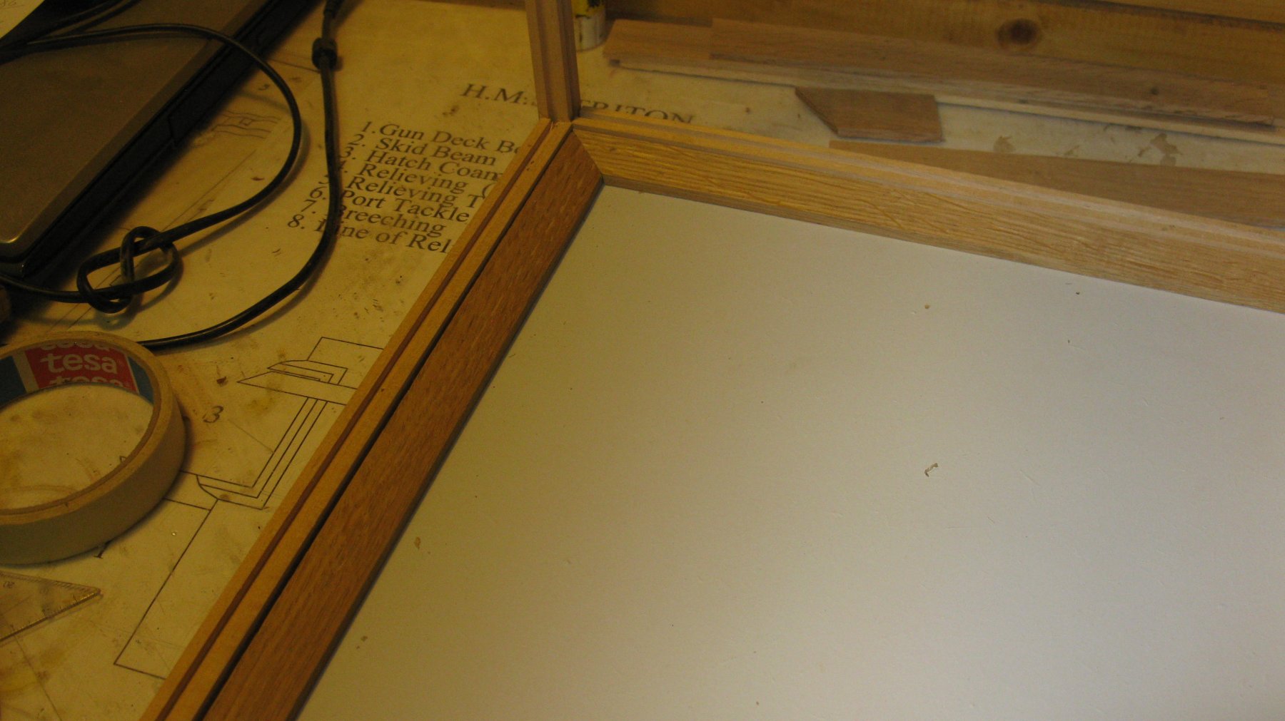
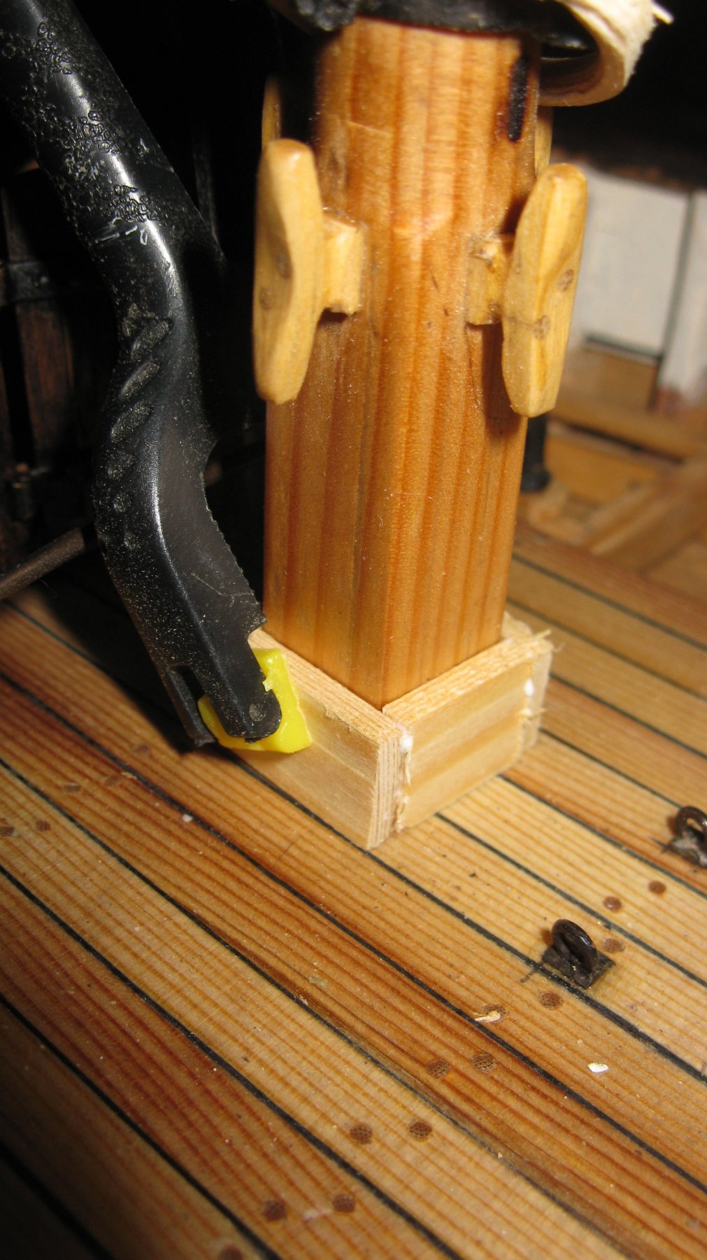
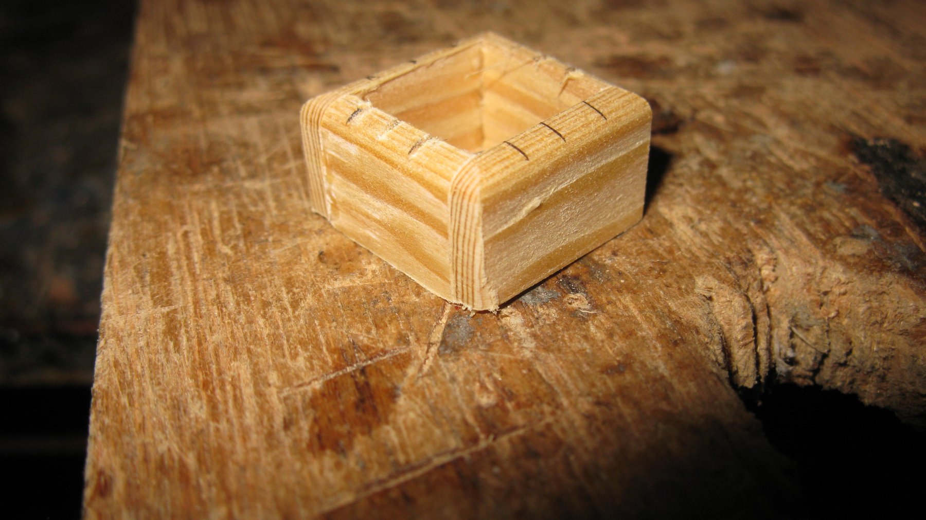
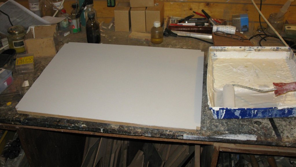
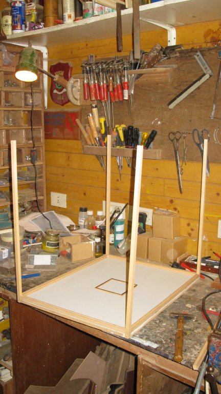
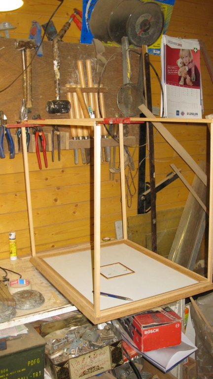
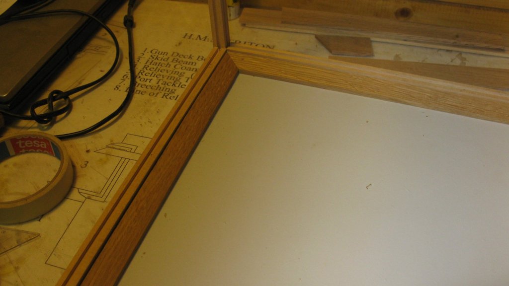
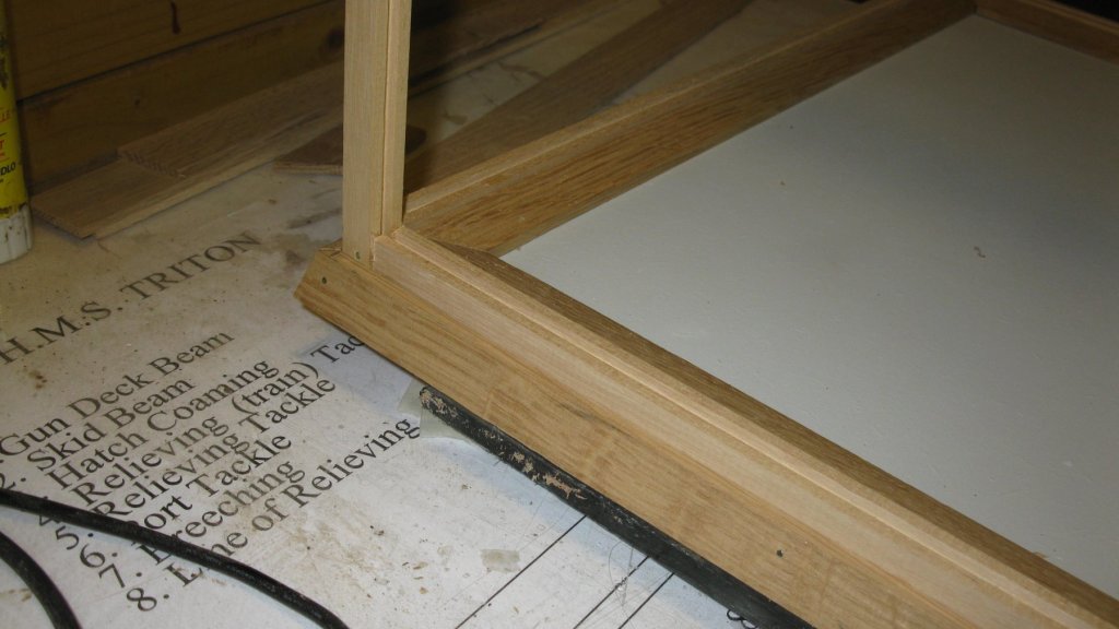
Thanks Patrick and Mark. Before showing some more pictures of the finished cross section, first some pictures of the making of a showcase. The base plate of the case is a MDF plate, painted in light grey. The small recesses at the corners will hold the four struts. In the middle I make a little cadre which fits in the bottom of pedestal to prevent the model to slide. The four struts are placed. Each strut has two grooves to hold a 3 mm glass plate. With the top frame placed. There is no glass yet in the case. The top frame is liftable to keep the showcase accessable. The inner edges are finished with mitred oak strips. The outer edges. The nail heads will be punched with a pin punch and the holes will be filled with malleable wood paste. The show case will be stained dark. The showcase with the cross section in it. The model on top of it is the 'Belgica' of my modeler friend Ward (can be followed on this forum). We meet with some ship modelers every month to show each other the progress of our projects and to share experiences.

-
To finish, the cross section is mounted on a pedestal made of dark hardwood.
-
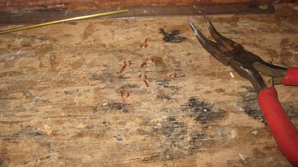
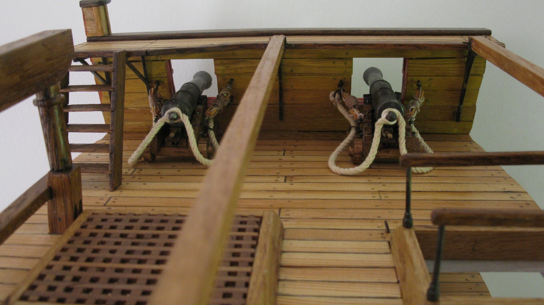
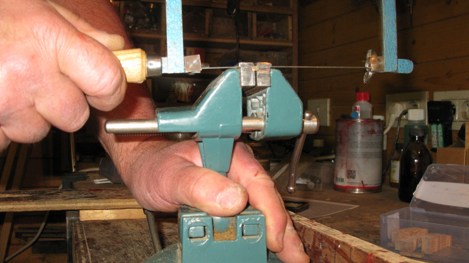
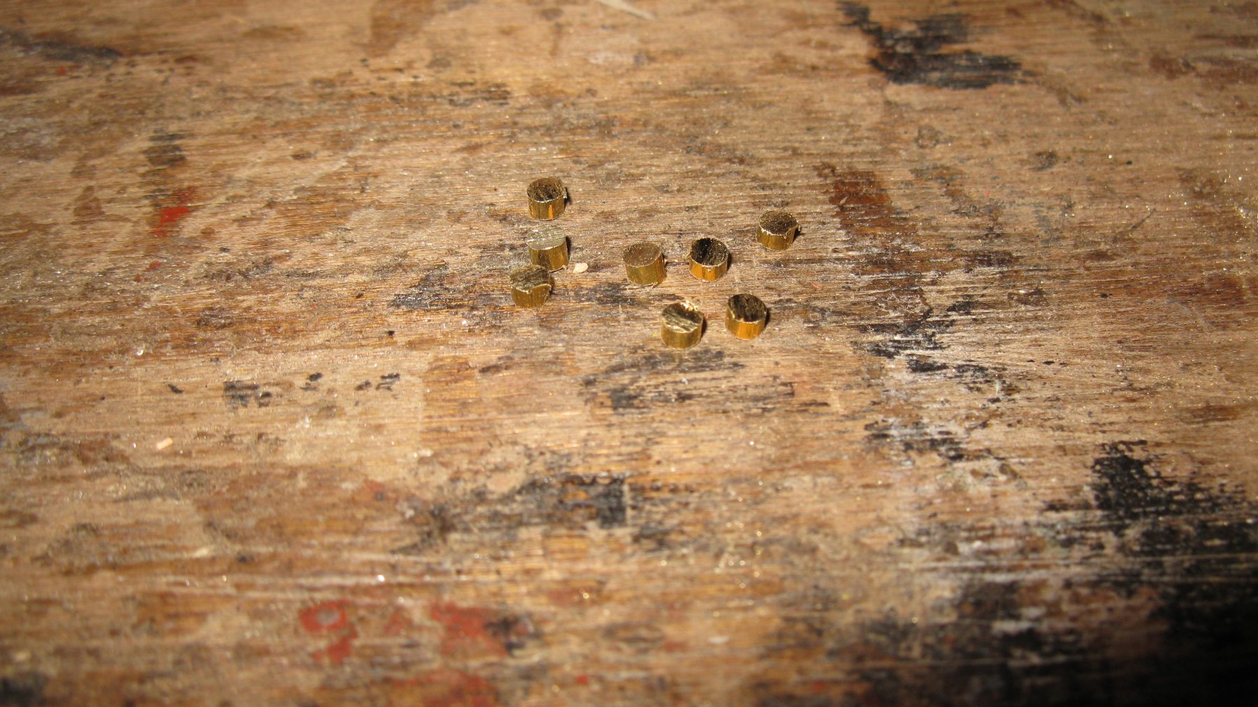
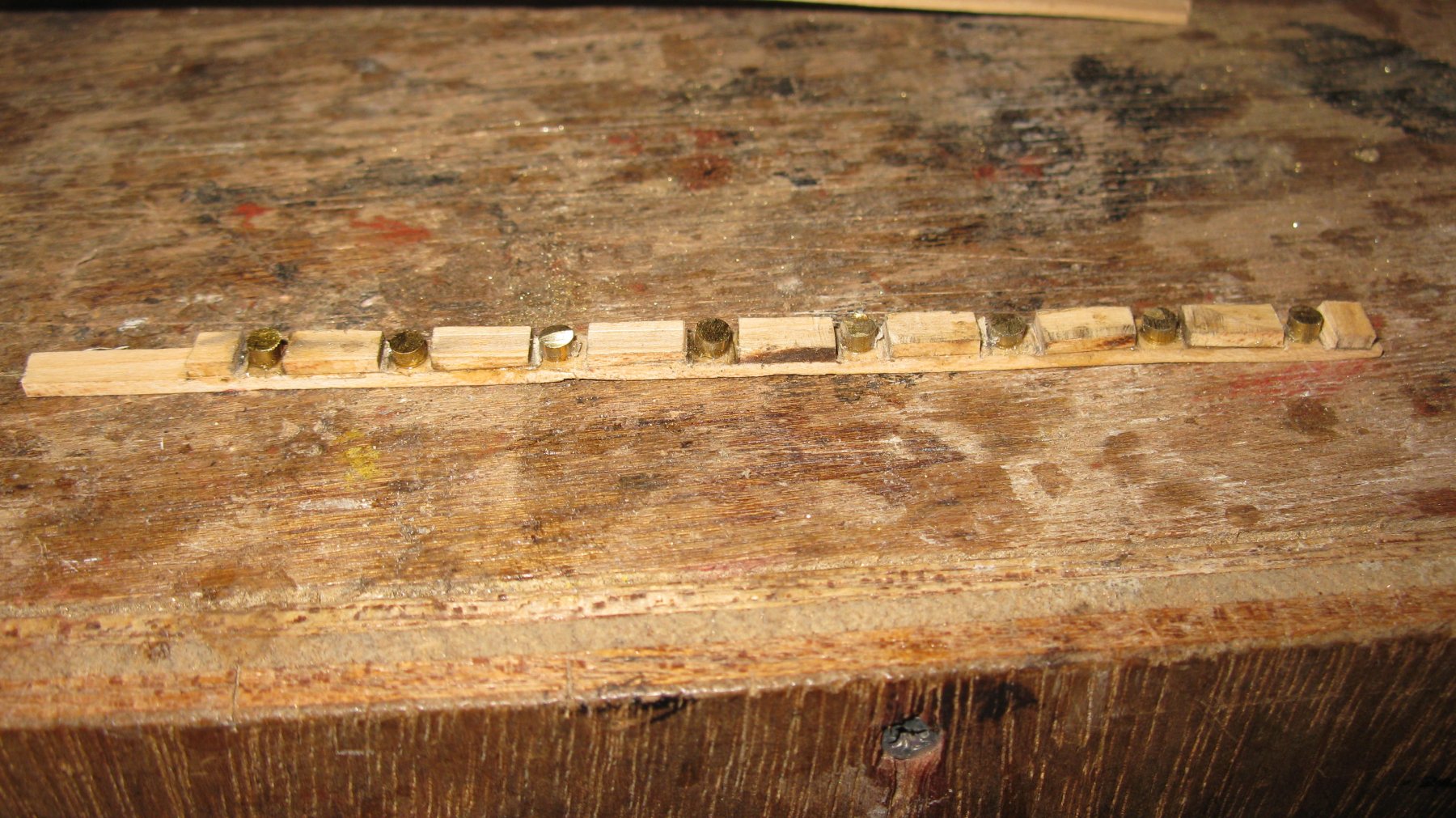
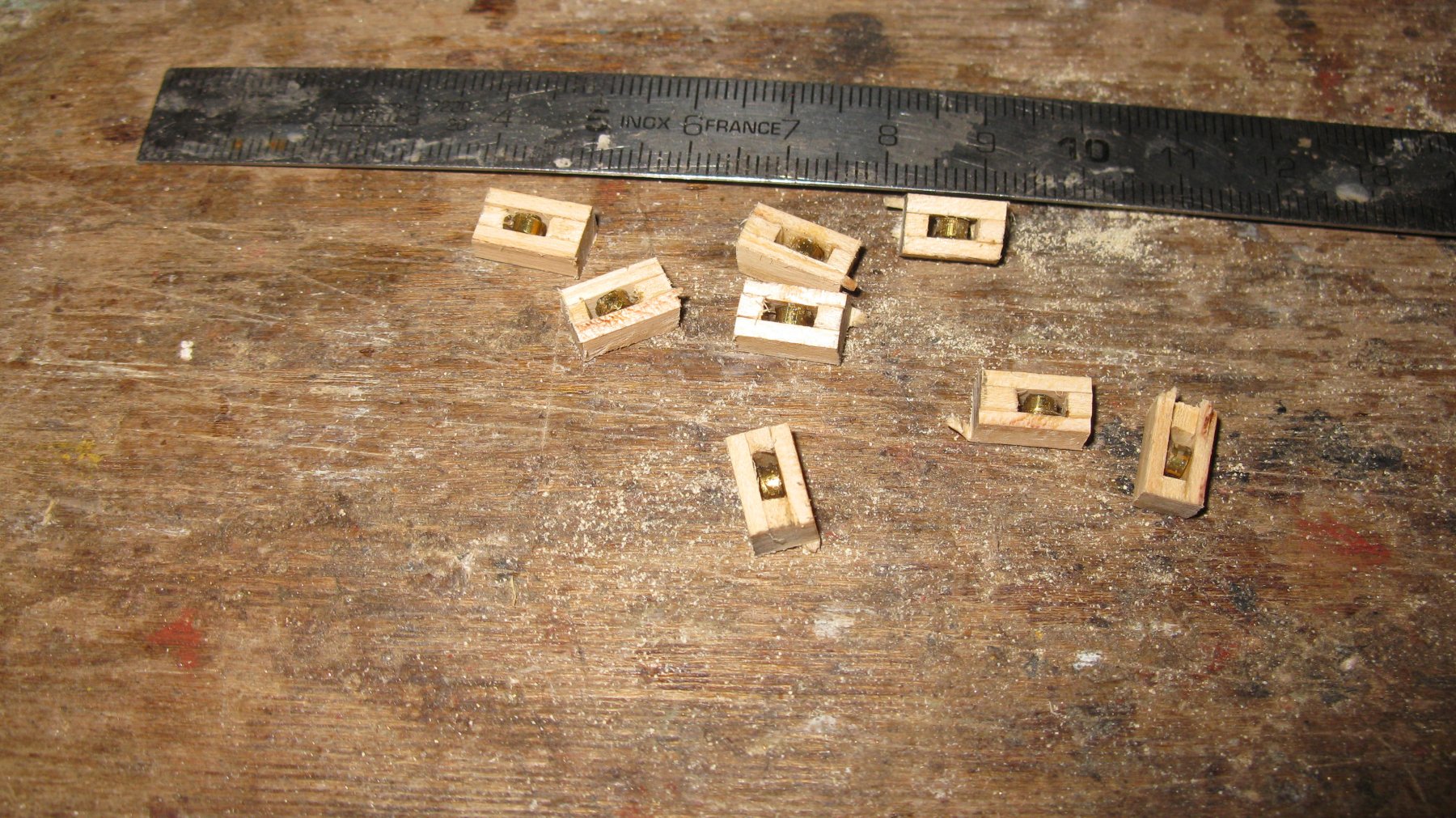
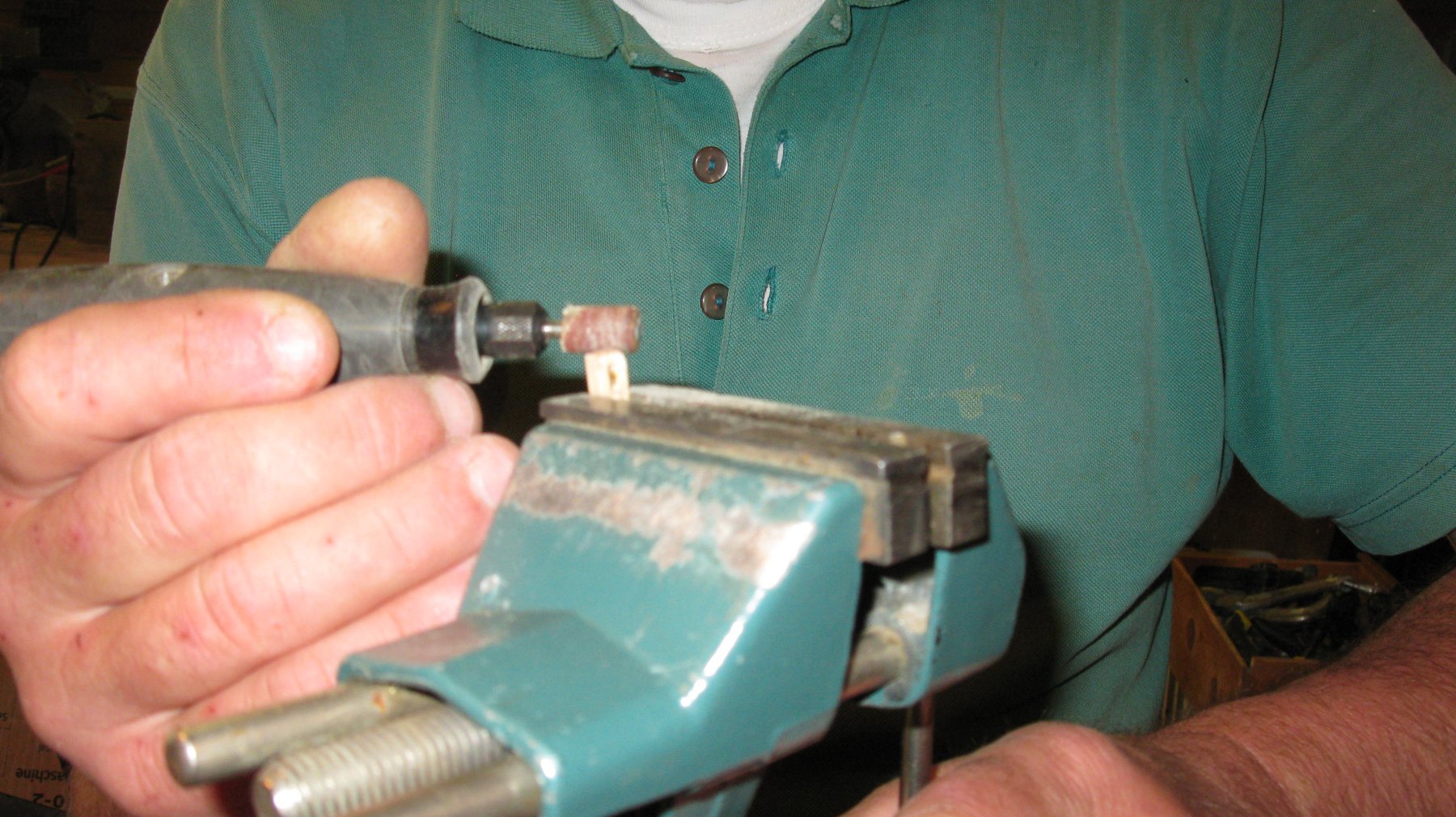
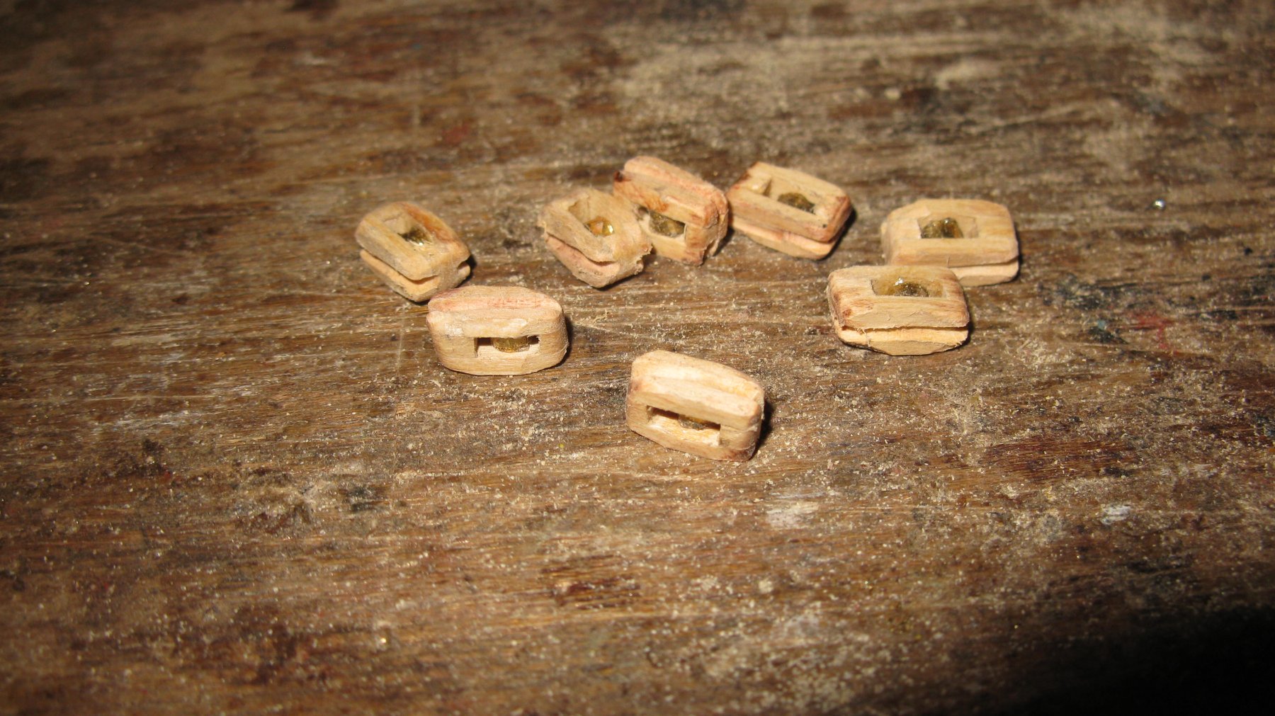
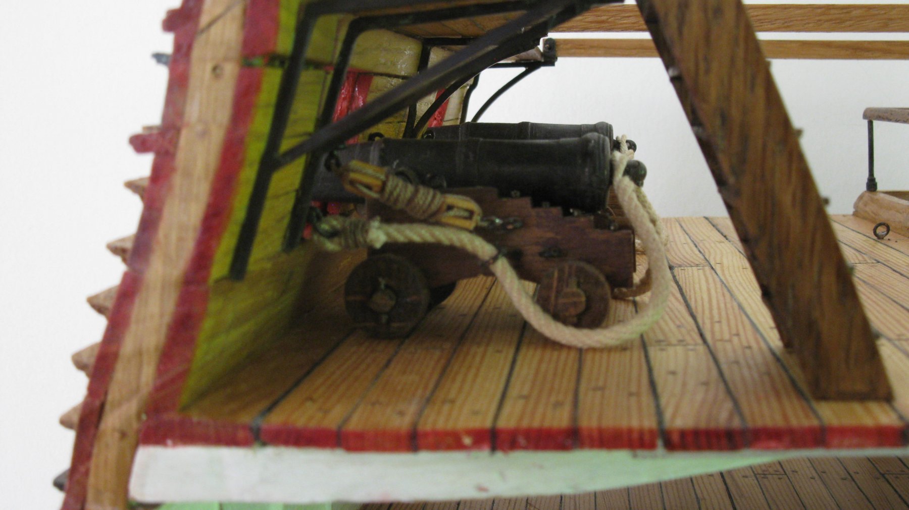
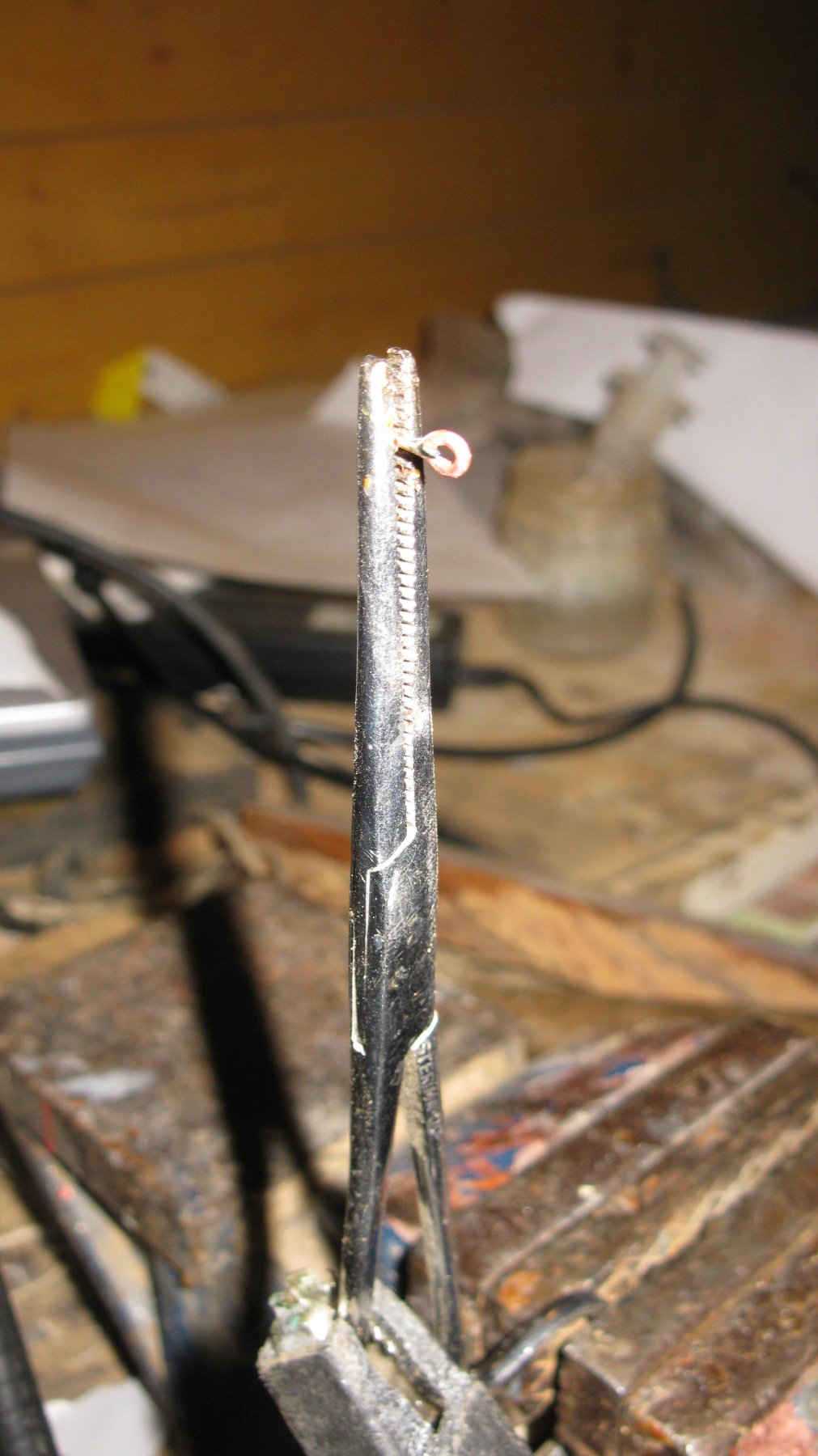
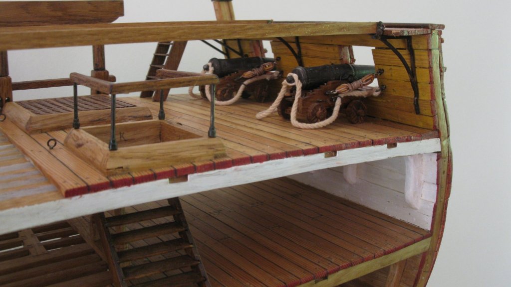
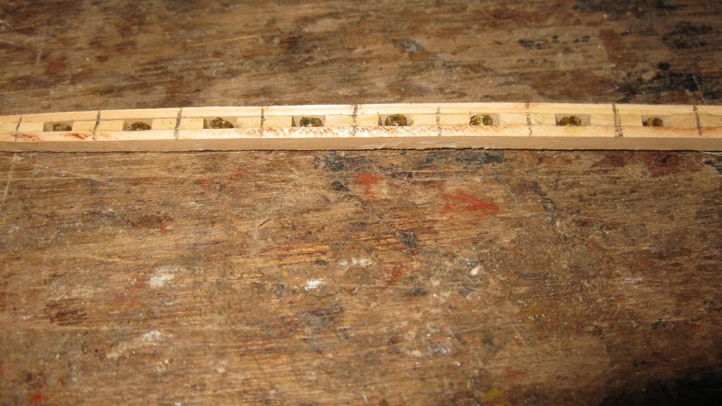
I will rig the guns in a secured for sea position (not ready for action). Therefore I need eight blocks. I saw first the sheaves for the blocks, 2mm slices of a brass rod ᴓ 3mm. My cross section is a stationary model, so the sheaves of the blocks must not be able to spin. I glue them on a small wooden lath on which are glued at regular intervals pieces of wood. Another lath is glued on top of it and the individual blocks can be sawn. The blocks need now some shaping and sanding and they are ready. The only further thing to do is rigging the two guns.


-
Thanks Jan. It has been a while since I made my last post. To be honest: I completed my cross section in the meanwhile, but during the last two sunny and hot months I disliked it to spend much time behind the desk and computer. Now I carry the consequences of my lazy behavior: I have to finish my story.
-
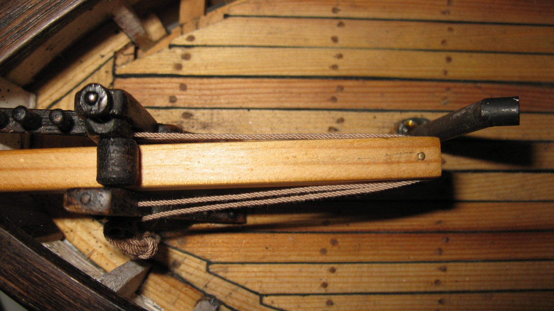
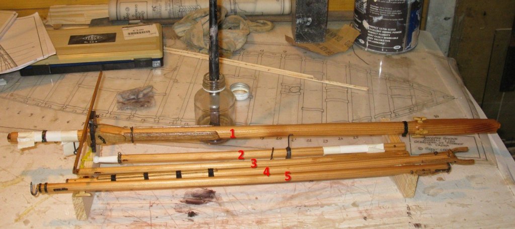
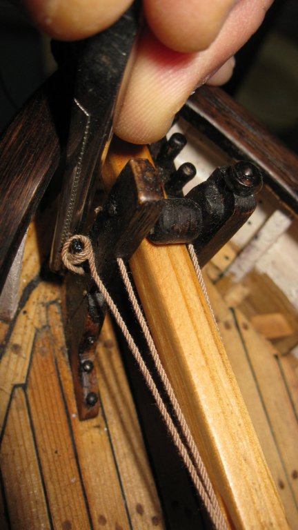
Thanks Ward, Patrick and WBlakeny and all wo liked. 17.9 Mast and spars It is already some months ago that I made the spars and now, looking to the photographs, I realize that I didn't make consequently photos during the making process. Probably too hasty to finish the job. I have this picture of all the spars together. From top to bottom: 1. Mast 2. Top gallant 3. Jib boom 4. Gaff 5. Boom And I have some pictures of the rigging of the jib boom.


-
Thanks for your answer, Patrick. I am glad that I was allowed to sail in a completely different era. G.L.
- 756 replies
-
- 3
-
-
- galleon
- golden hind
- (and 2 more)
-
Patrick, Are the crew heads just the holes or did they have something to sit on? G.L.
-
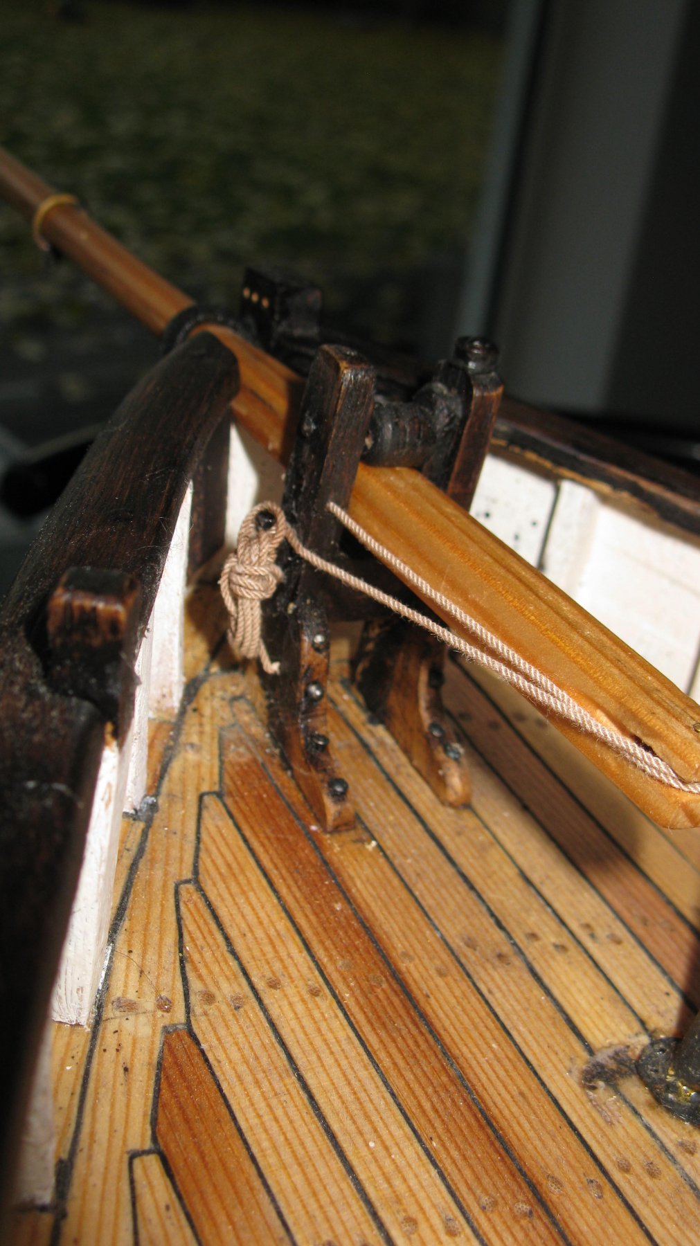
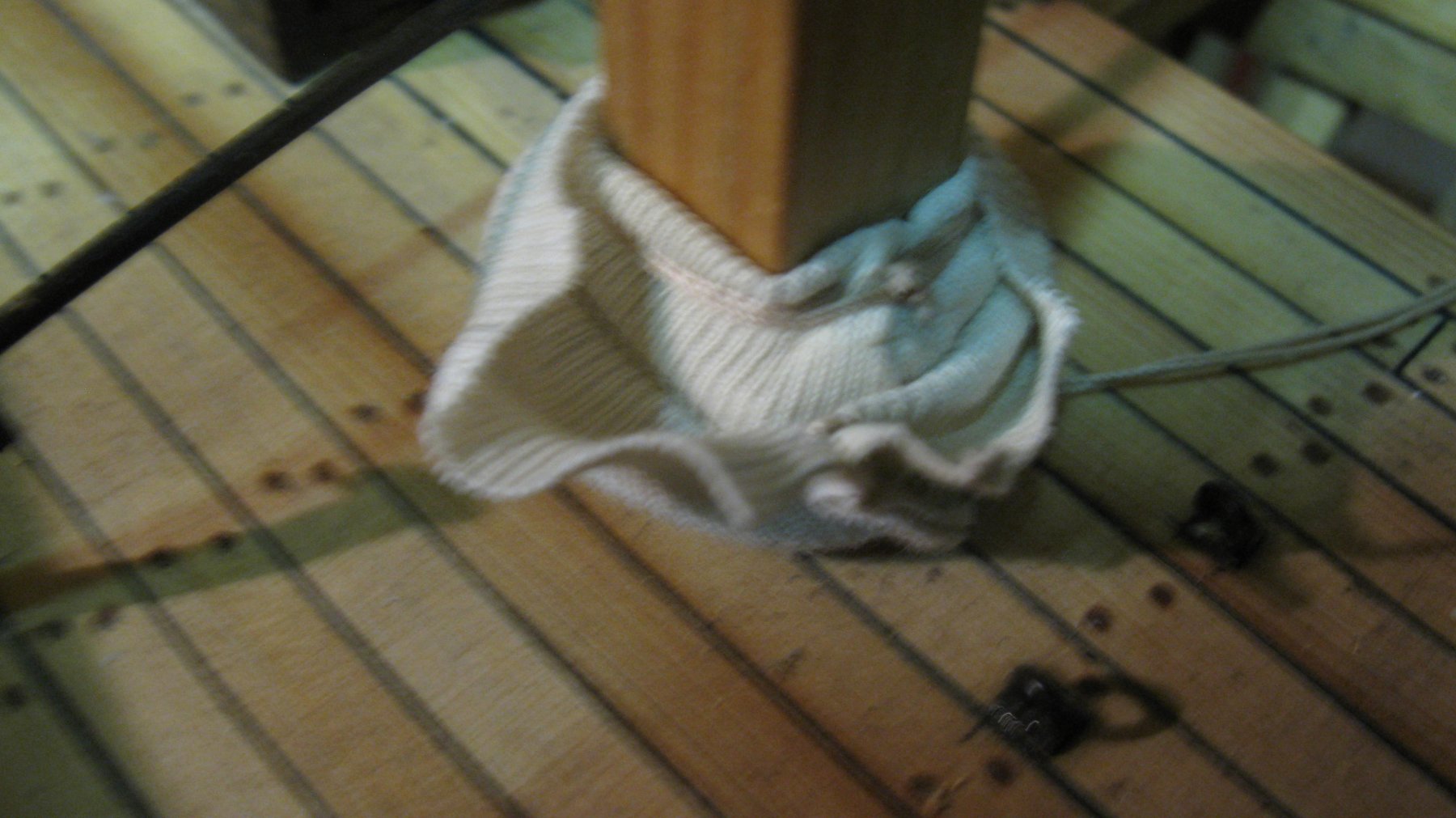
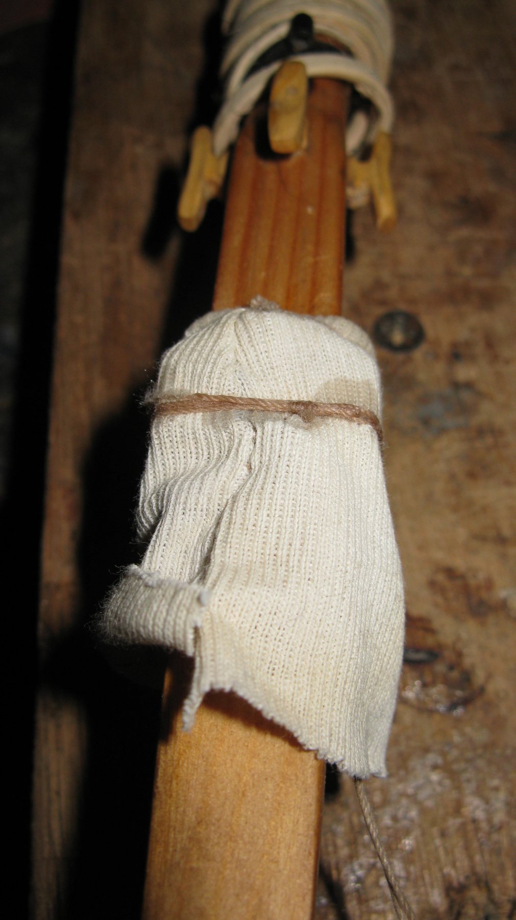
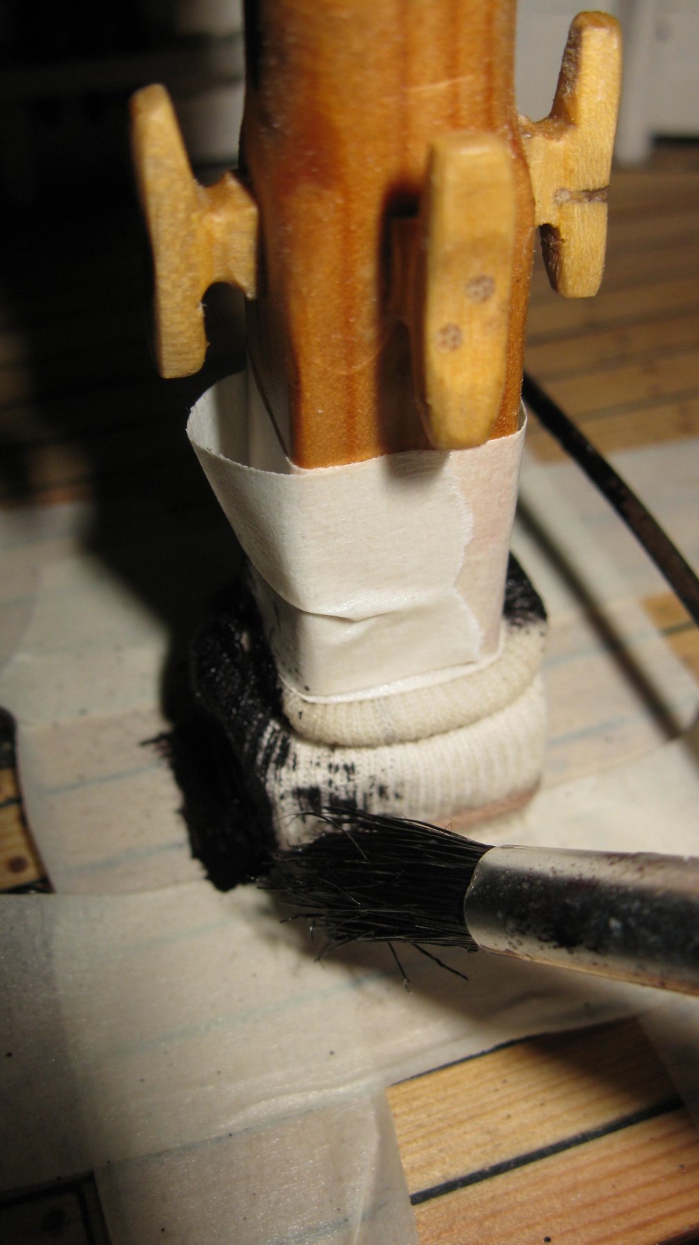
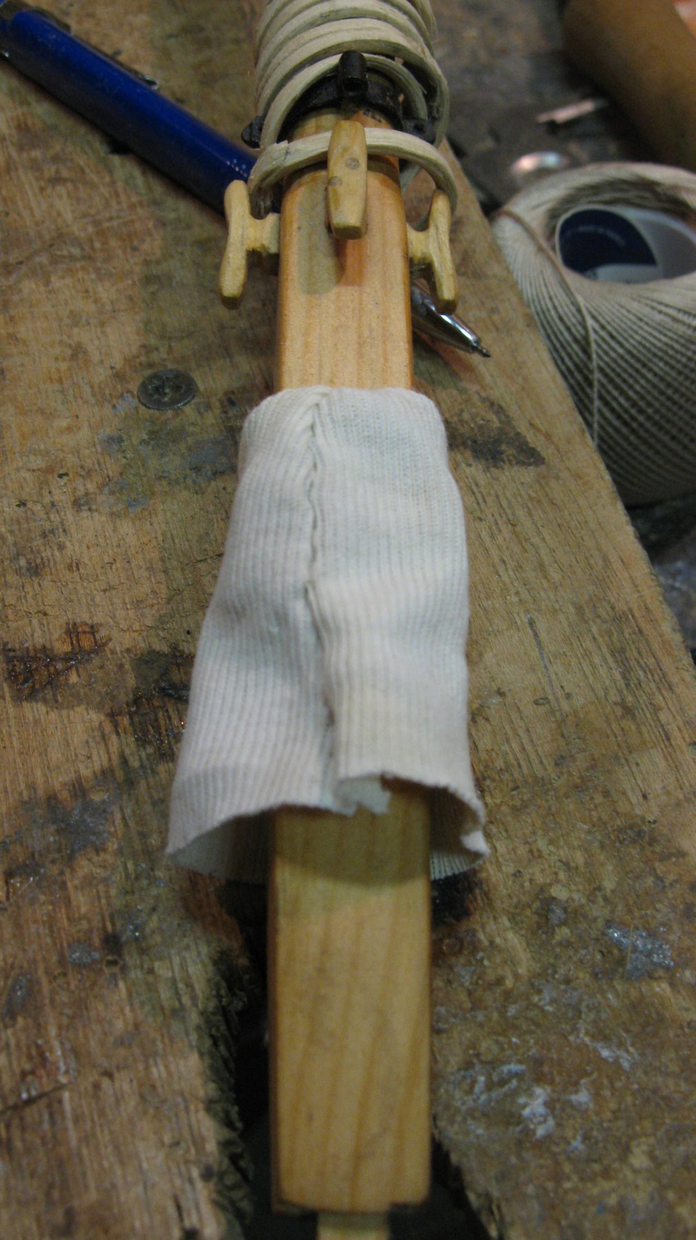
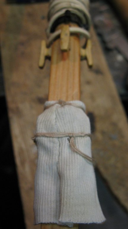
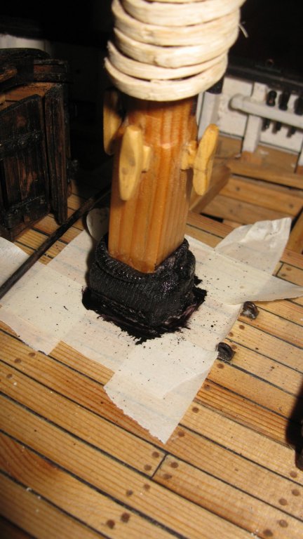
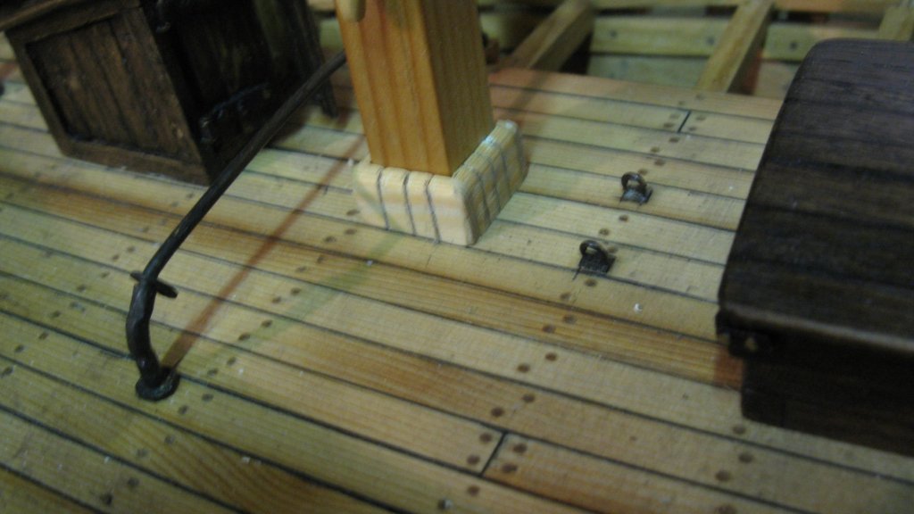
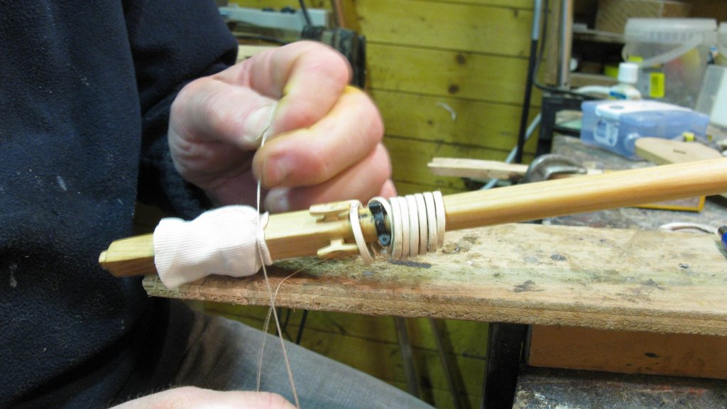
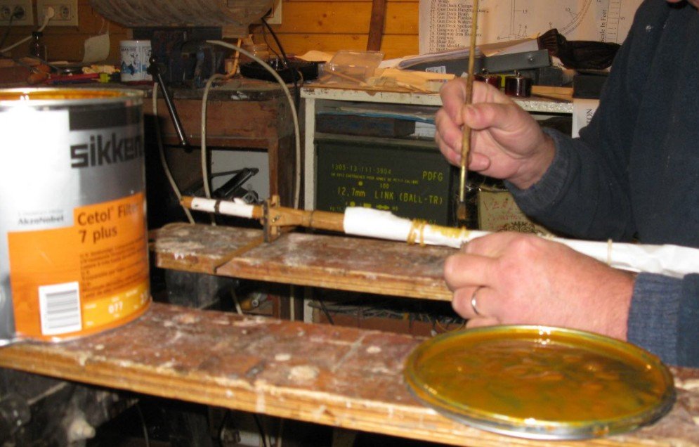
The sock is tied again just at the bottom of the wedges. I fix the binding with glue and cut of the excess at the deck level. The canvas on fishing sloops was sealed with tar. I seal it with acryl paint. The mast sealing


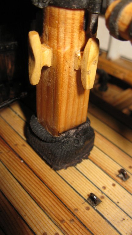
-
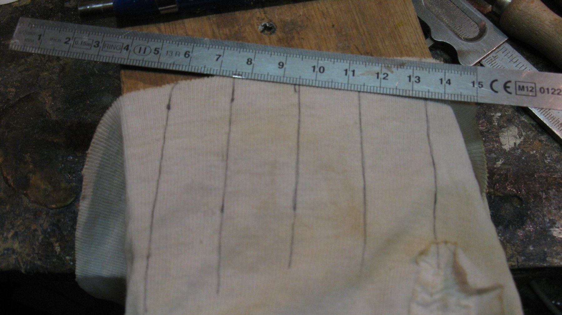
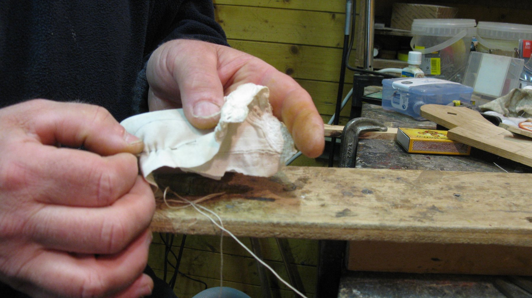
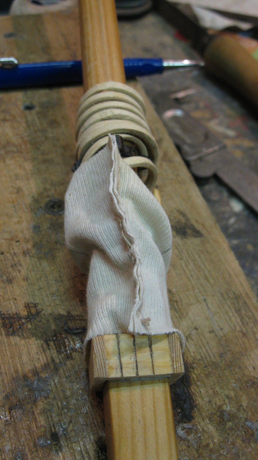
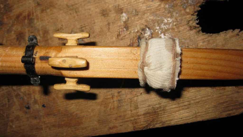
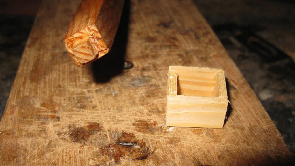
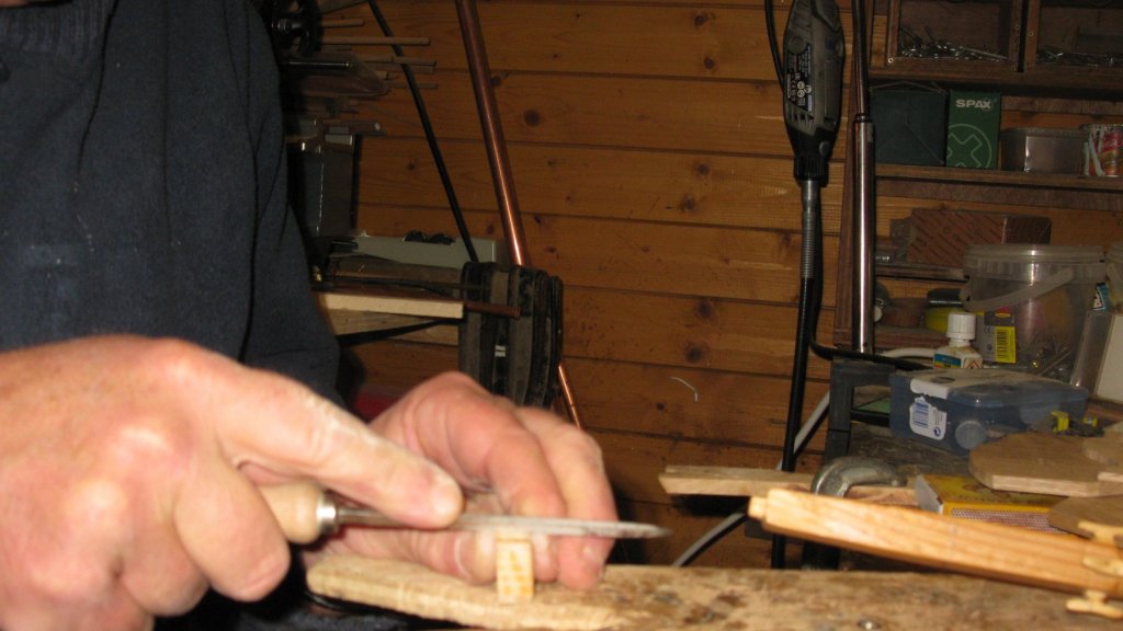
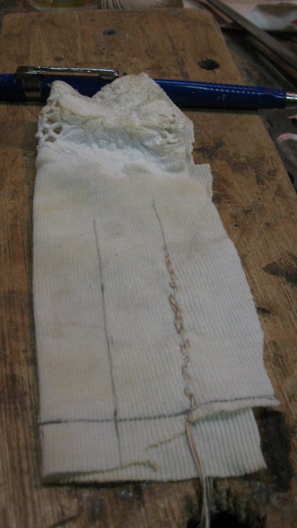
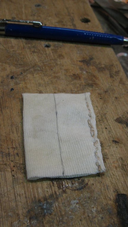
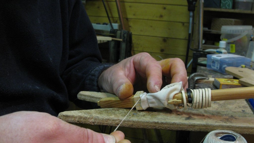
Thank you, Ward. 17.8. Mast. Mast seal The wedges of the mast sealing will be covered with canvas so limit myself to make a simple wooden upholstery around the mast. To give it anyway somewhat a look of wedges I saw and carve grooves in it. I take piece of tissue to make the canvas sealing and draw the sizes of the four sides of my wedges square on it. I sew it together to a kind of sock and cut the sides right. I slide the sock over the mast step and tie the top at the inside just above the wedges. I pull the sock back down and tie nit again at the outside.


-
Finally I understand the name Aviaamator. Nice hydroplane! G.L.
-
My congratulations with the successful completion. The model looks very fine. It is also interesting to see an other type of vessel than the usual 'western' style ship. G.L.
-
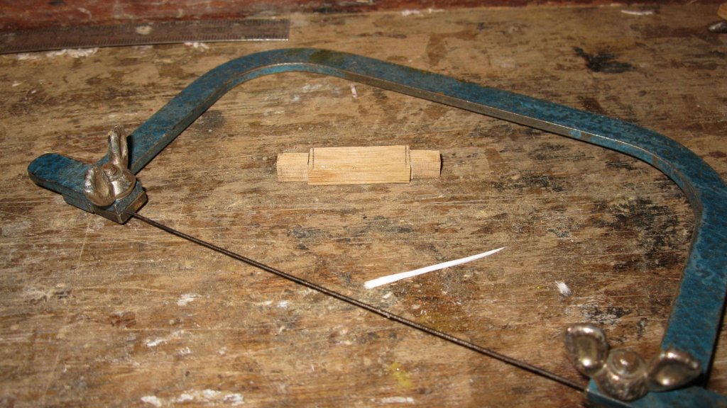
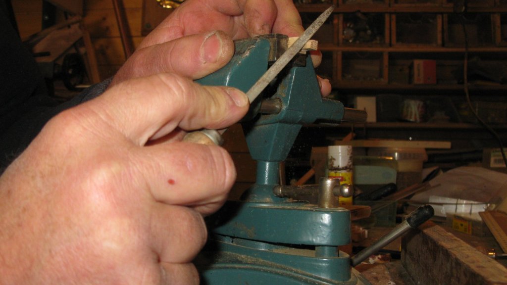
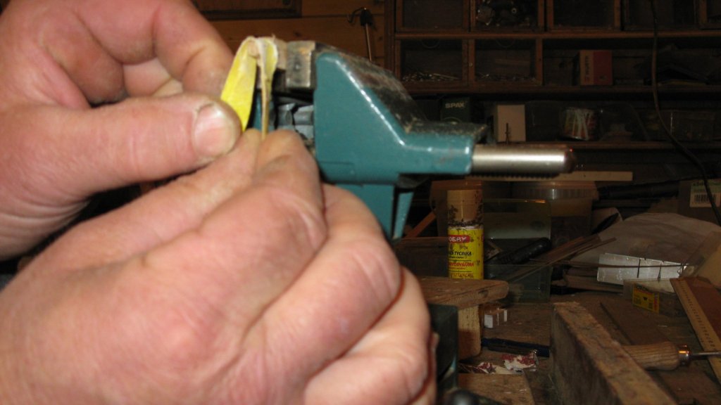
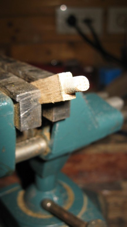
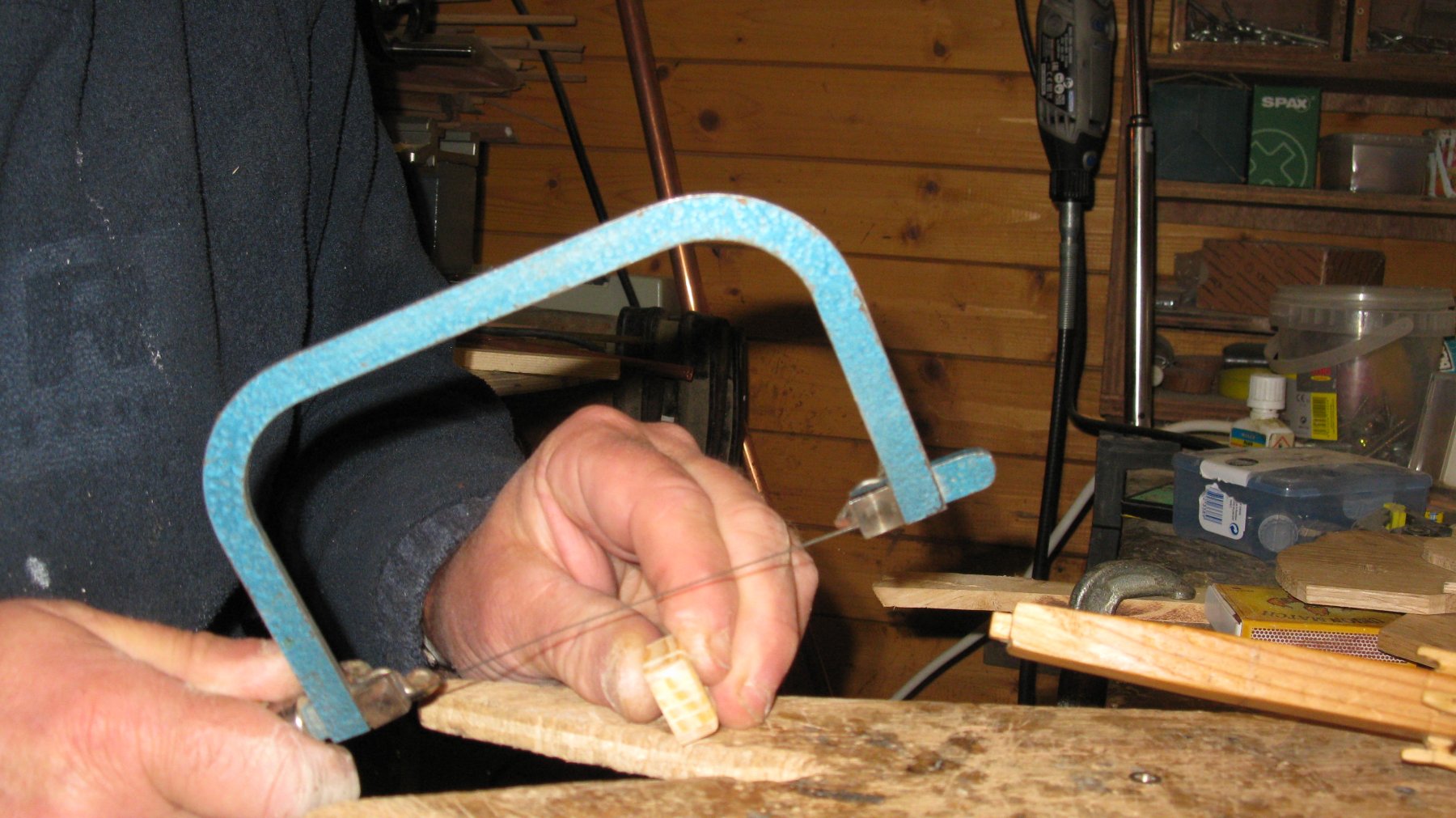
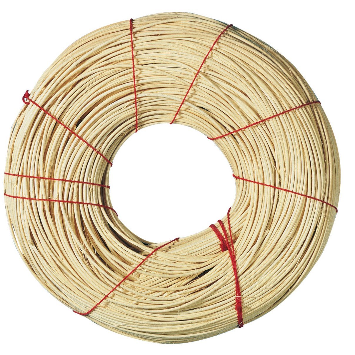
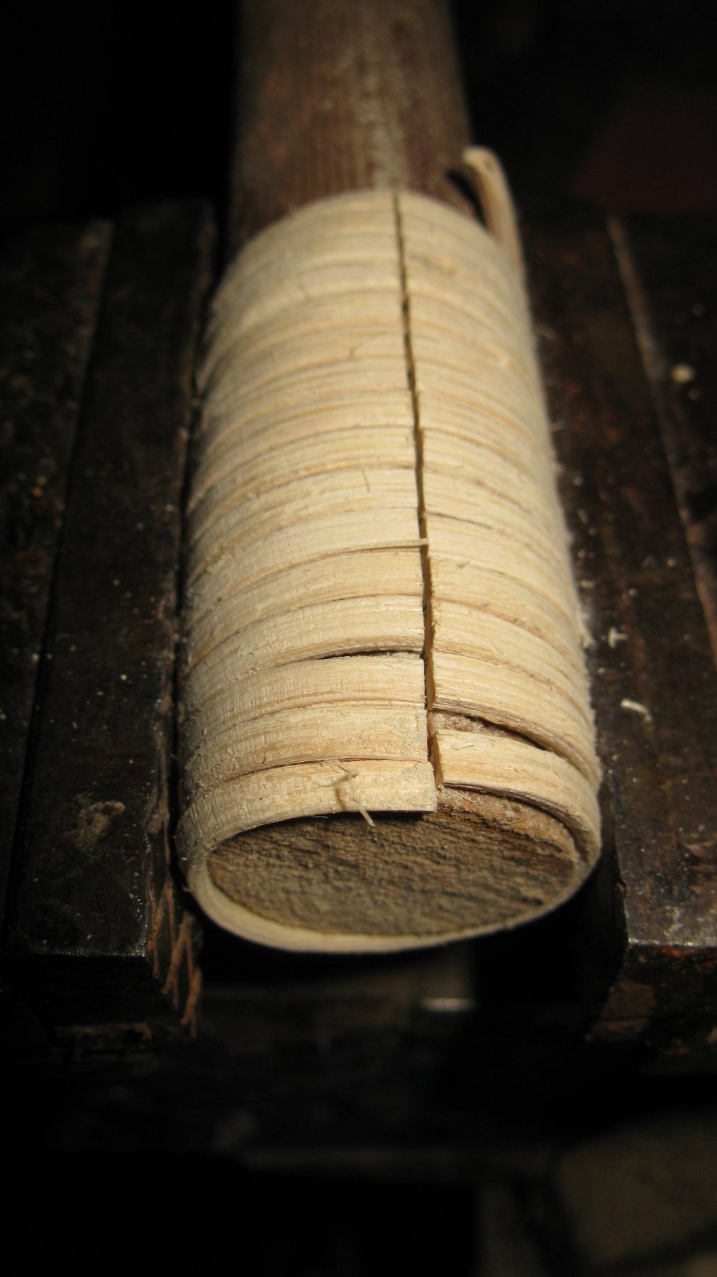
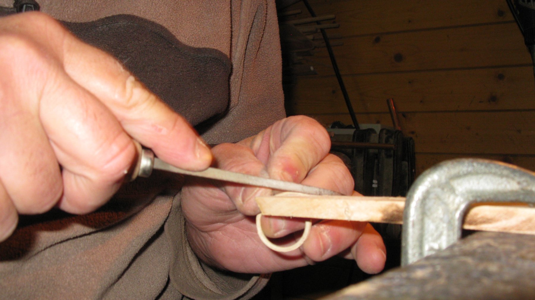
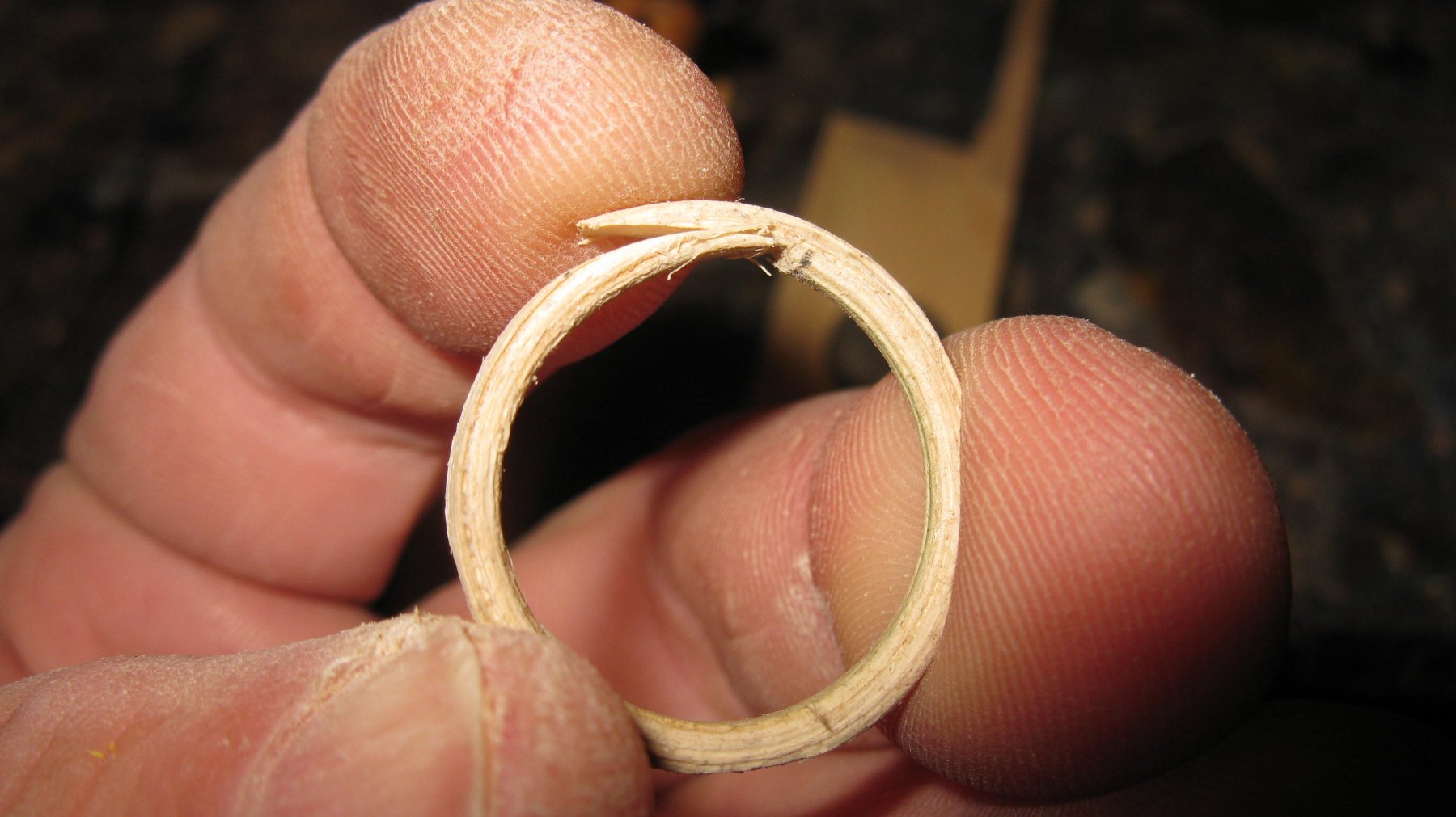
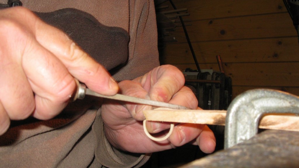
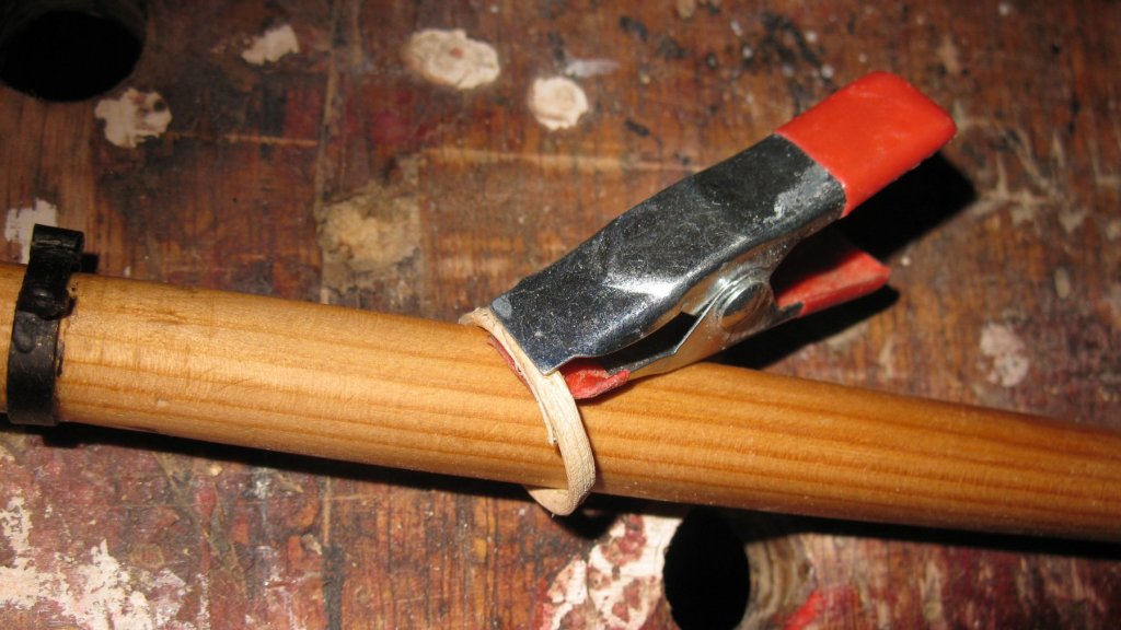
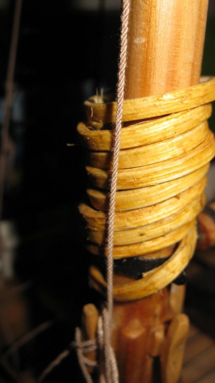
17.7. Mast. mast hoops The mainsail is attached to the mast with 6 mast hoops. I make my hoops with pit cane (in Dutch: pitriet). It can be bought in a roll in hobby stores and is mainly used to weave baskets and for flower arranging. I scrape one side of a piece of the cane flat. After being soaked in water for a while it becomes very flexible and I turn it around a piece of tube with a diameter which is some wider than that of the mast, the flat side at the outside. When it is dry the cane keeps its spiral form when it is removed from the tube and it can be sawn to separate rings. I file the ends of each ring diagonally. One side at the inside, the other at the outside. They must fit one in another to make a sustained ring. The rings are now glued together around the mast. Now I protect the mast with some paper under the rings and stain the rings. I have made some more rings than the 6 needed. When rigging the sail, I will choose the best of them.


-
HMS ROYAL KATHERINE 1664 by Doris - 1/55 - CARD
G.L. replied to DORIS's topic in - Build logs for subjects built 1501 - 1750
Amazing!! G.L.- 1,035 replies
-
- 5
-
-
- royal katherine
- ship of the line
- (and 1 more)
-
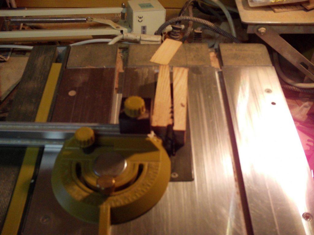
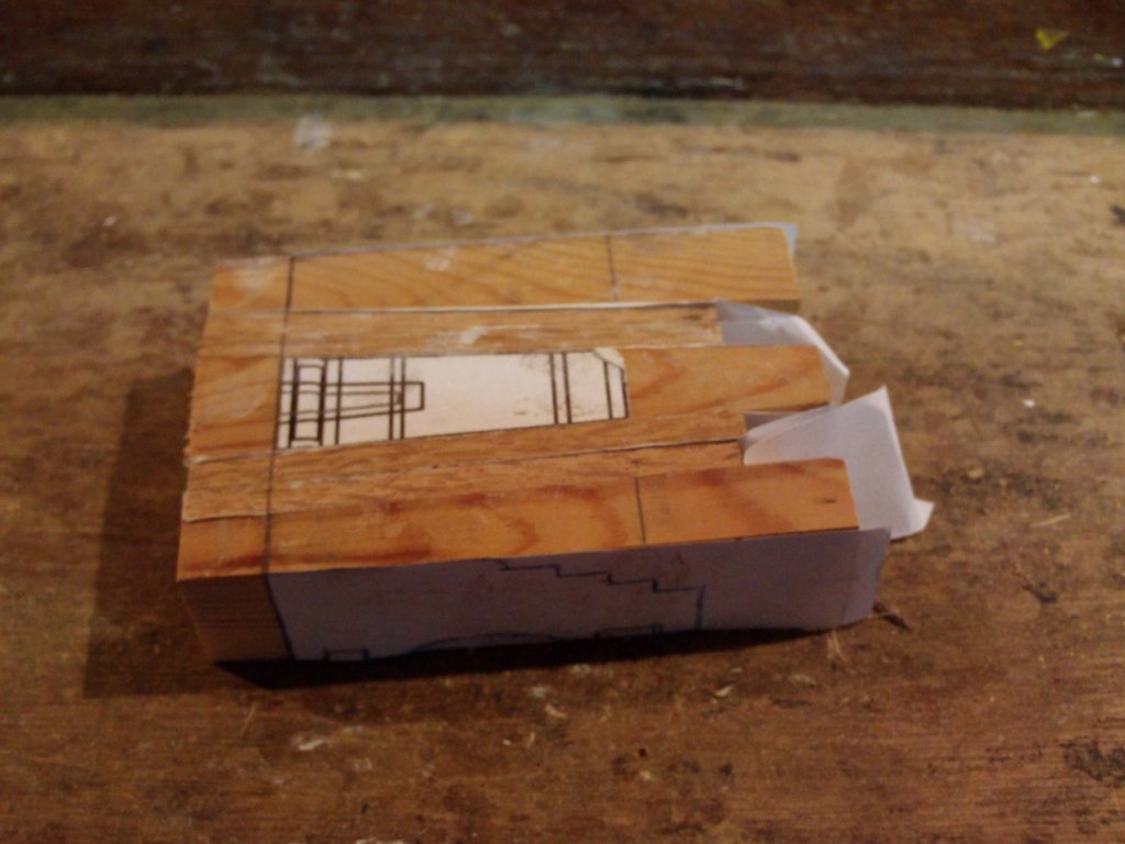
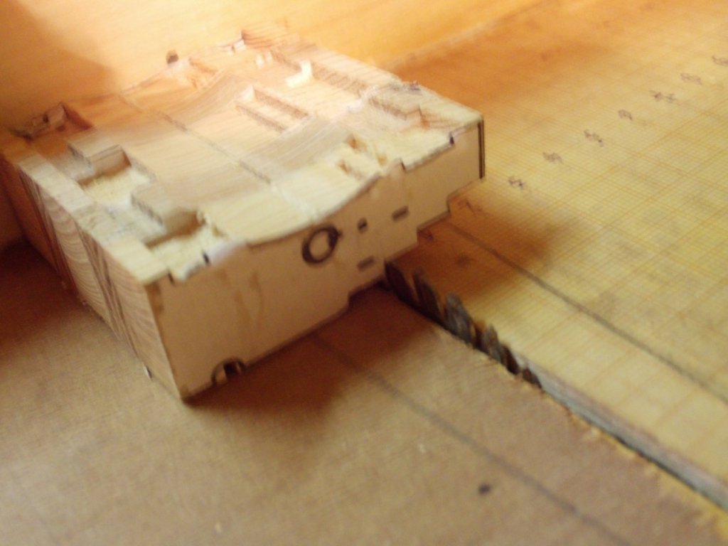
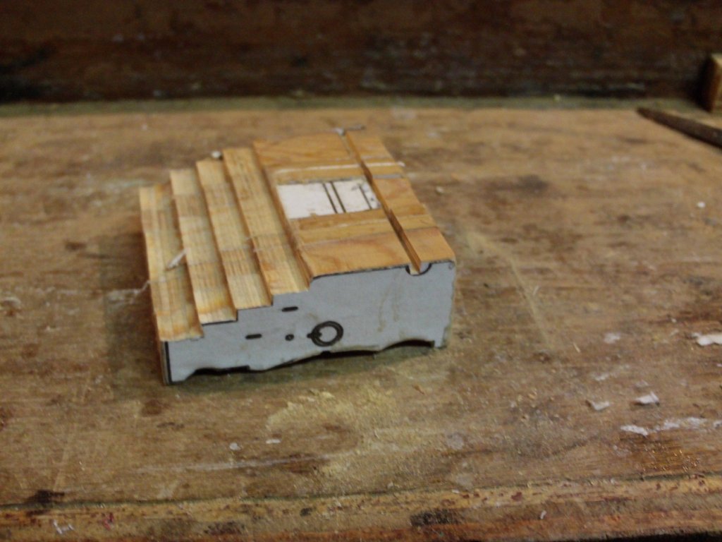
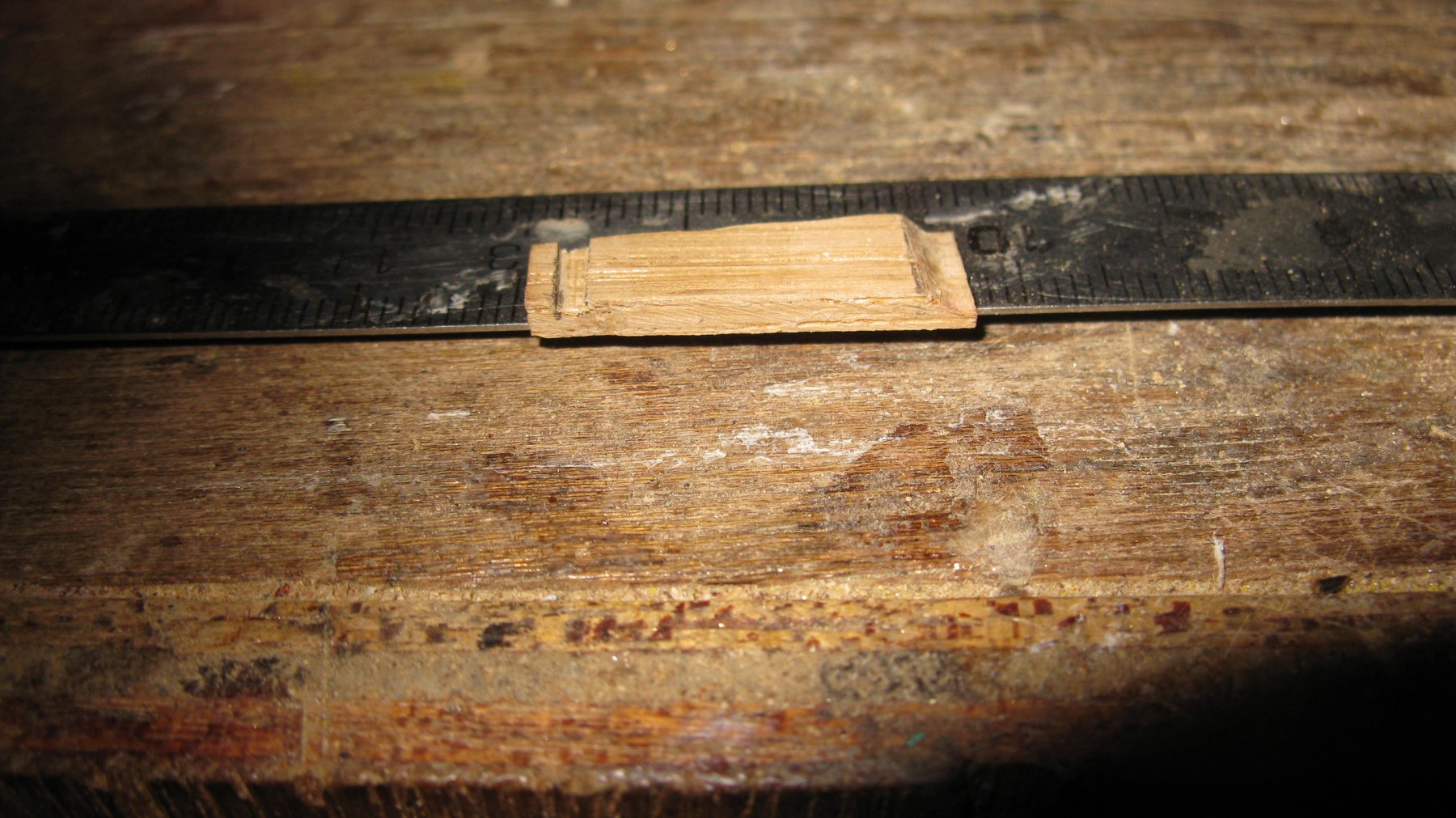
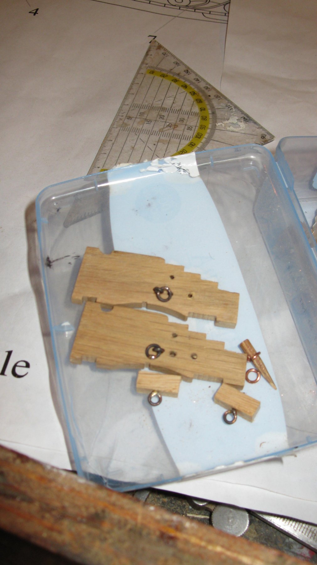
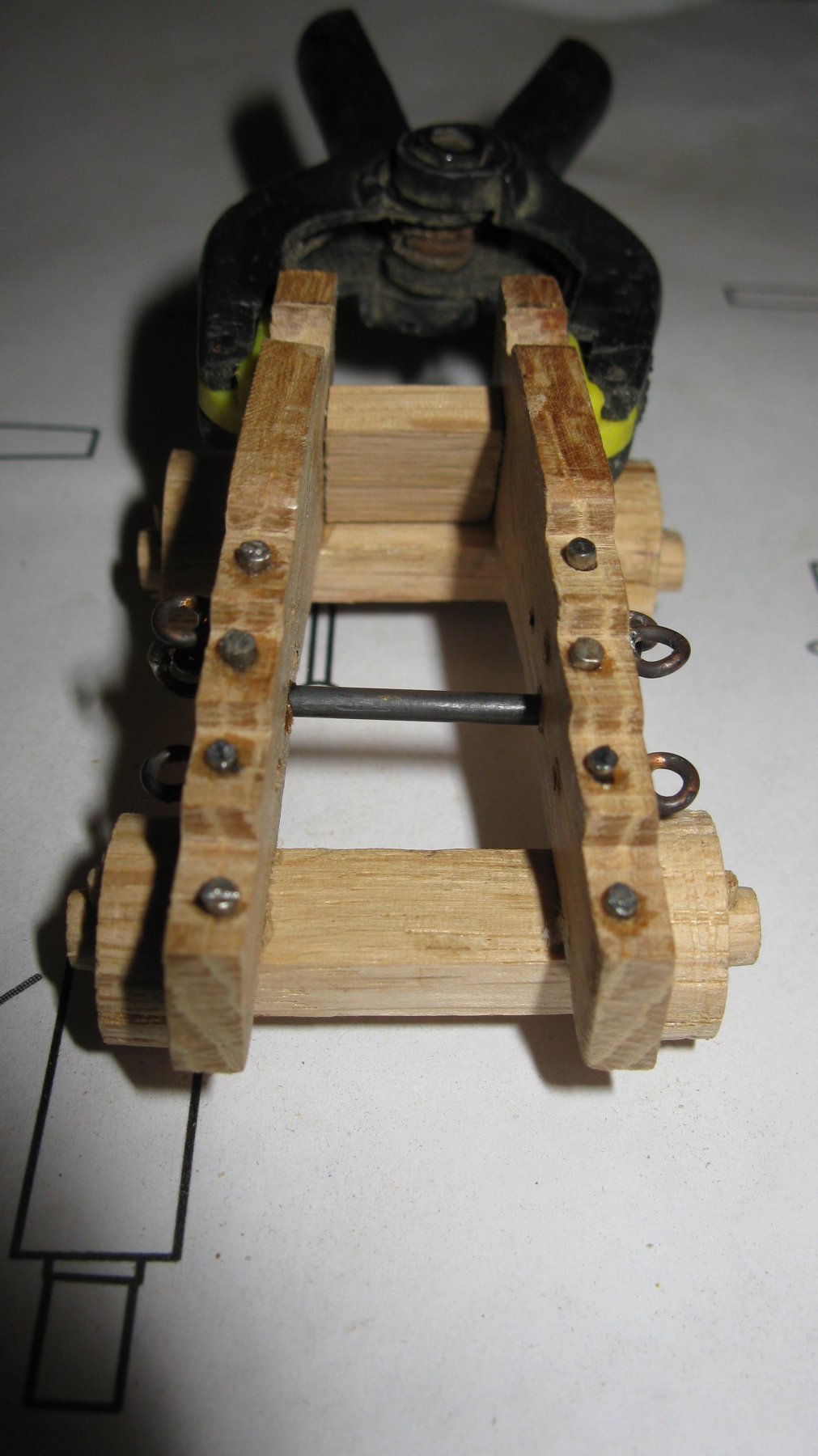
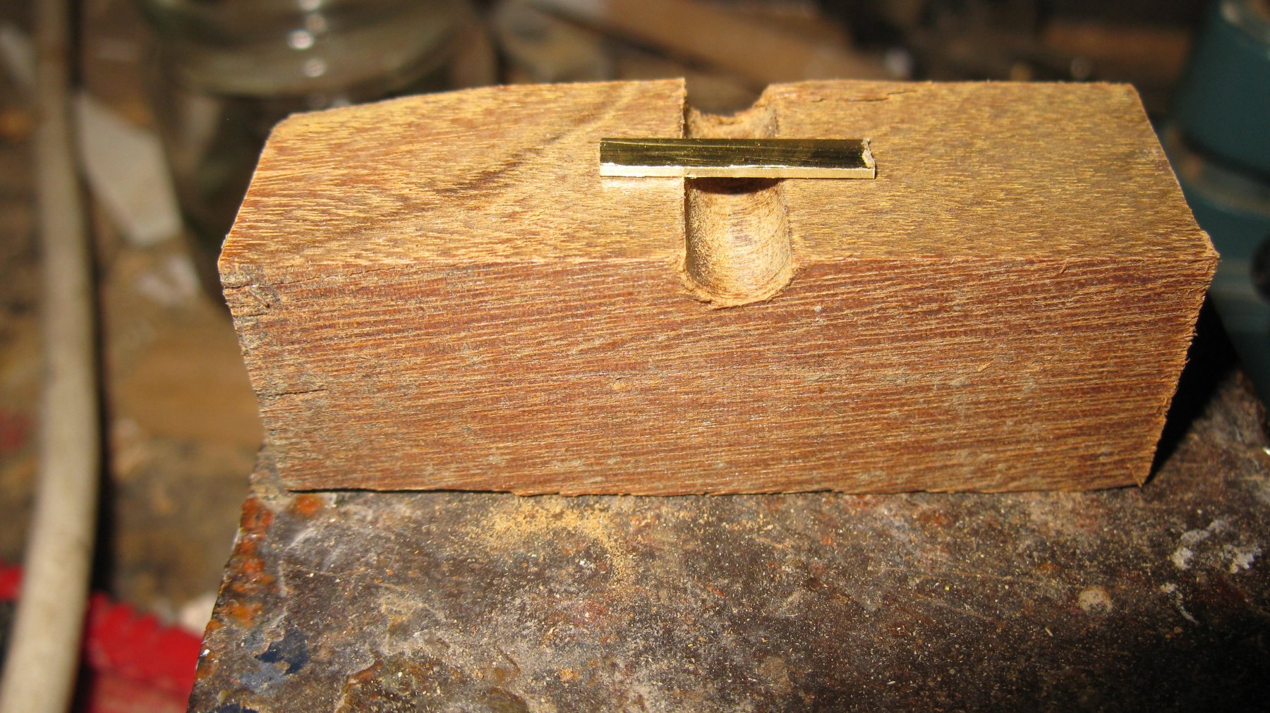
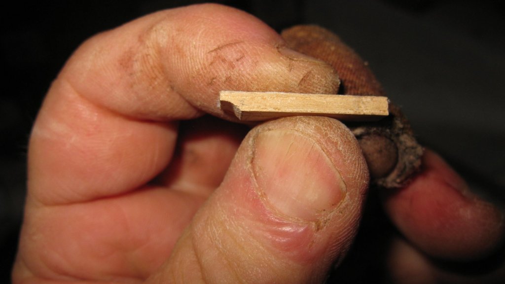
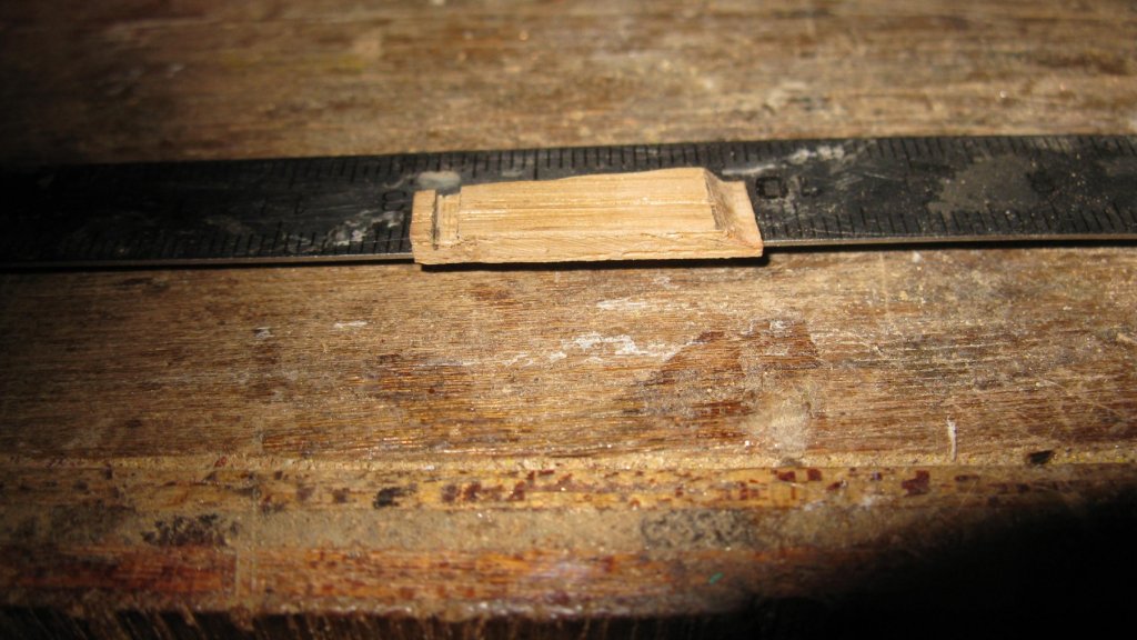
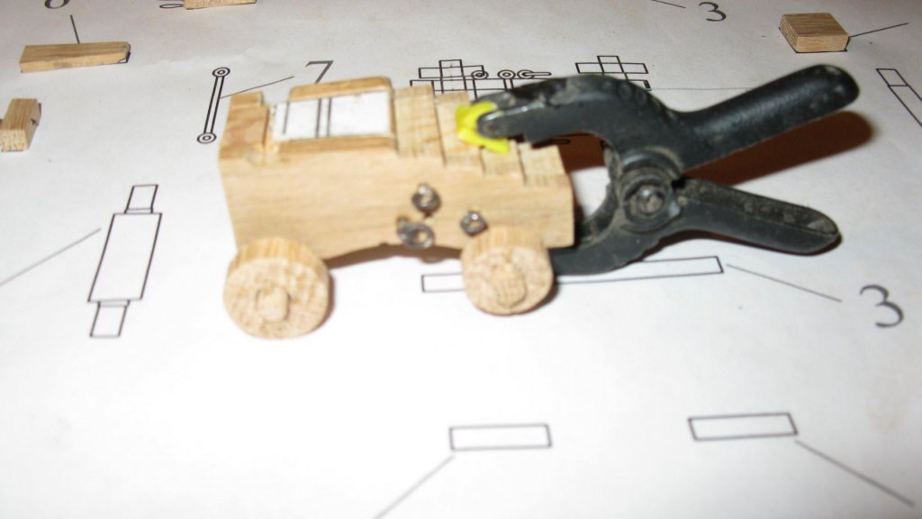
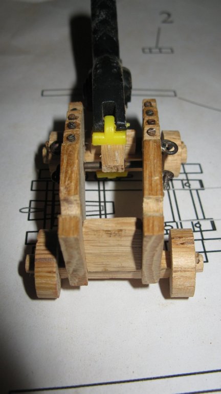
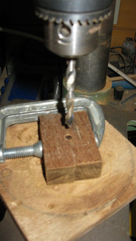
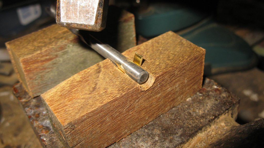
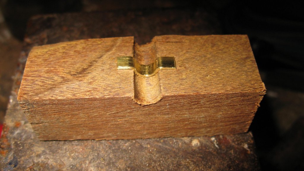
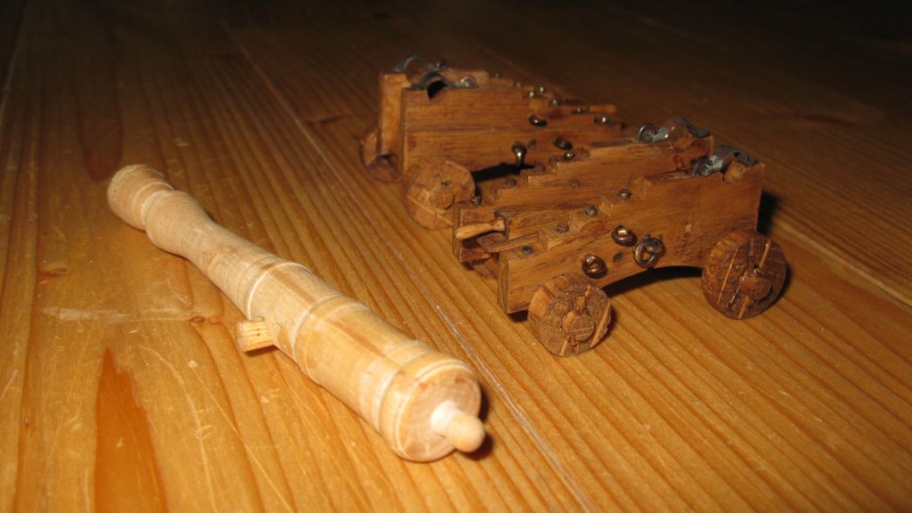
The small side of the stool bed must have a rounded notch. I make it with a round file The bed lays with a nick on the metal truck. The nick is sawn out with the jigsaw. The parts of the gun carriage The gun carriages are assembled with the help of the middle piece of the jig. Gluing the transom. Gluing the stool bed To make the cap squares I make simple jig. I saw a piece of hard wood in two, clamp the two halves together and drill a hole in the middle. Foto 360 Giving form to the cap squares is now simply done with the help of a drill and a hammer. Two finished gun carriages after being stained.


-
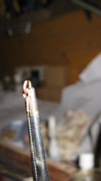
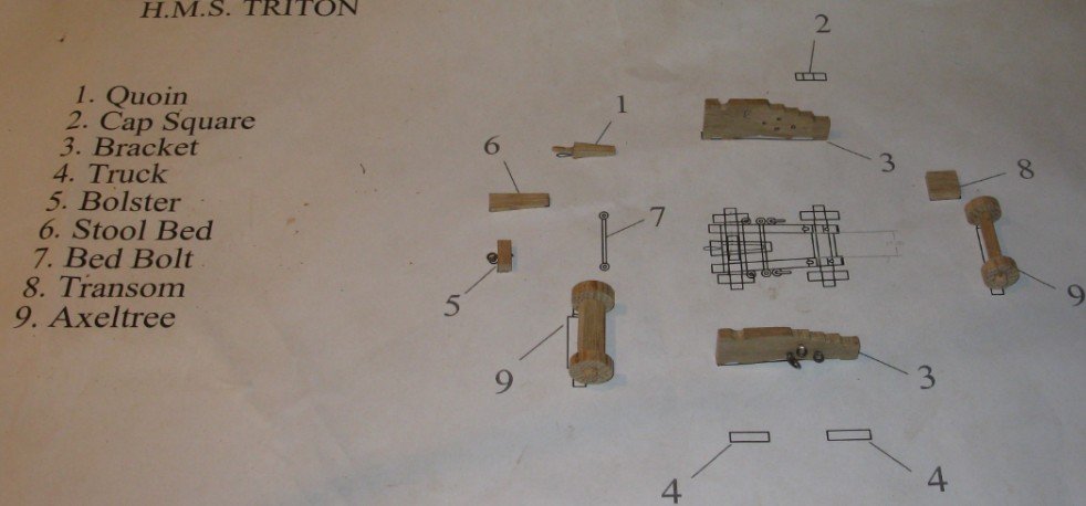
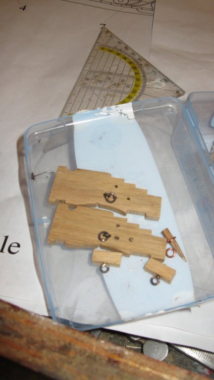
I think that something went wrong with the post of my last report therefore I repost it. To make the gun carriages, I refer to the log Cross section HMS Triton log of Tkay11. Tony wrote an in my opinion very clear handout to make the carriages. I follow his handout for the most part and do not intend to rewrite everything that he wrote before. I will only expatiate where I went my own way. Sawing the jig for the gun carriages assembly. The jig with the brackets for 2 carriages in it. Sawing the brackets for 2 carriages in one go. Making the axel trees. Here I went some more artisan than Tony. I sawed out the wheel axles square with the jigsaw Then I filed and sanded the square axles round. Plying and soldering the rings. Foto 347, 348, 349