G.L.
-
Posts
1,553 -
Joined
-
Last visited
Content Type
Profiles
Forums
Gallery
Events
Everything posted by G.L.
-
 Dave, I discovered this morning your log of the HMS Blandford cross section. Looks like a engaging project, on scale 1/32 it will become a very nice model. I subscribe to follow your log. Wishing you an interesting build. Lots of regards,
 -
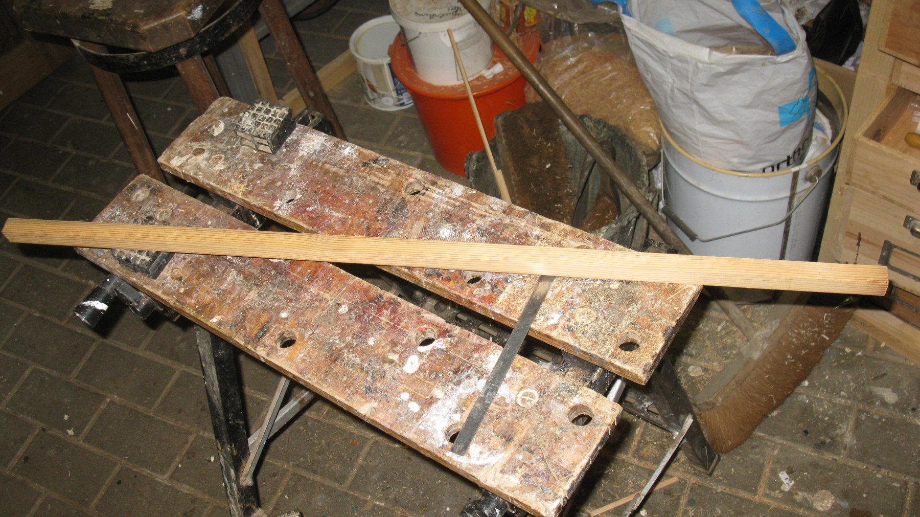
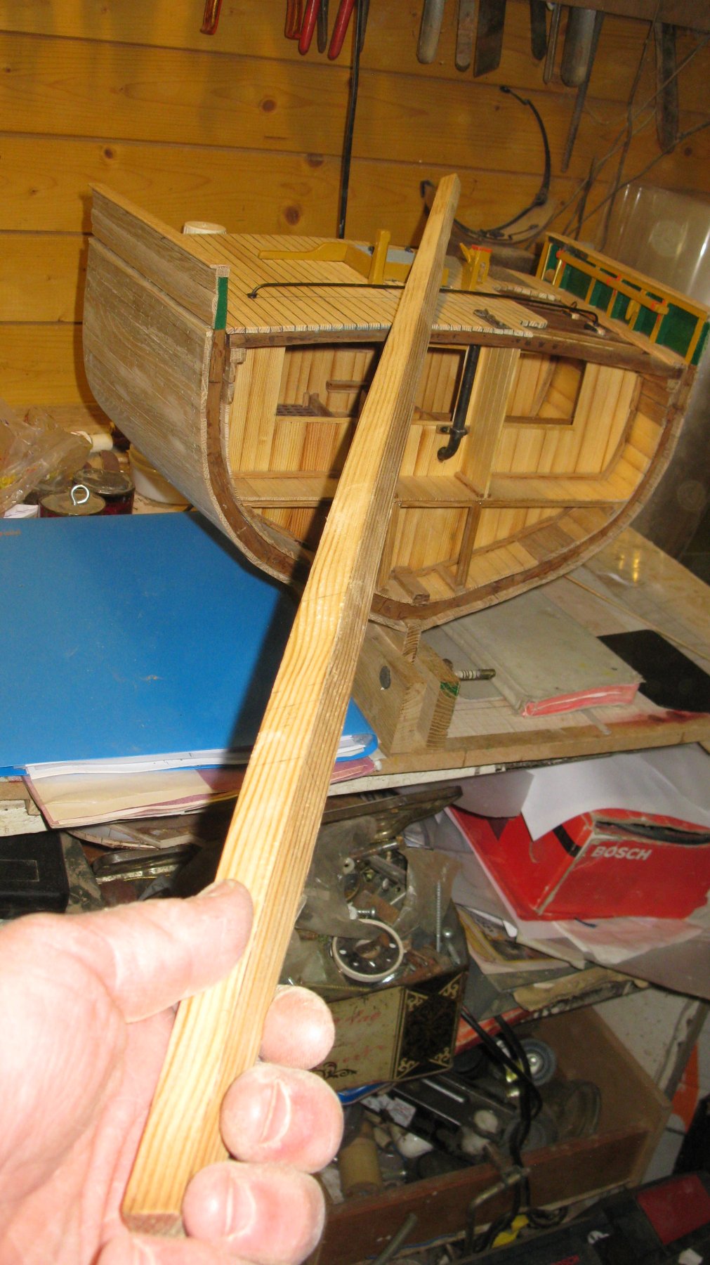
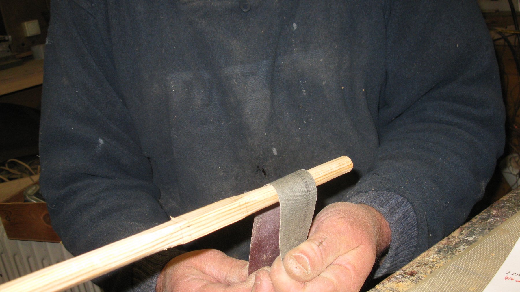
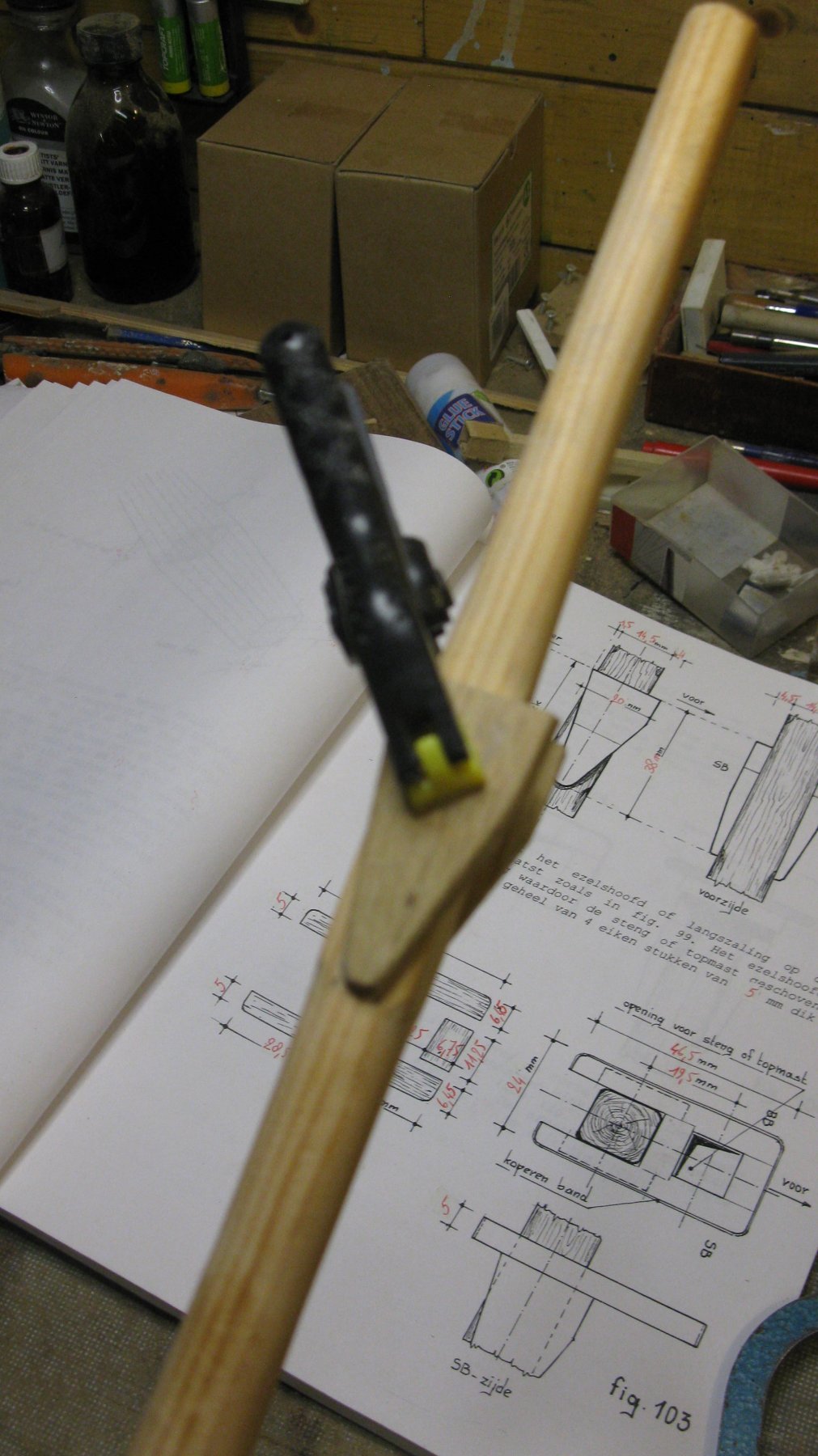
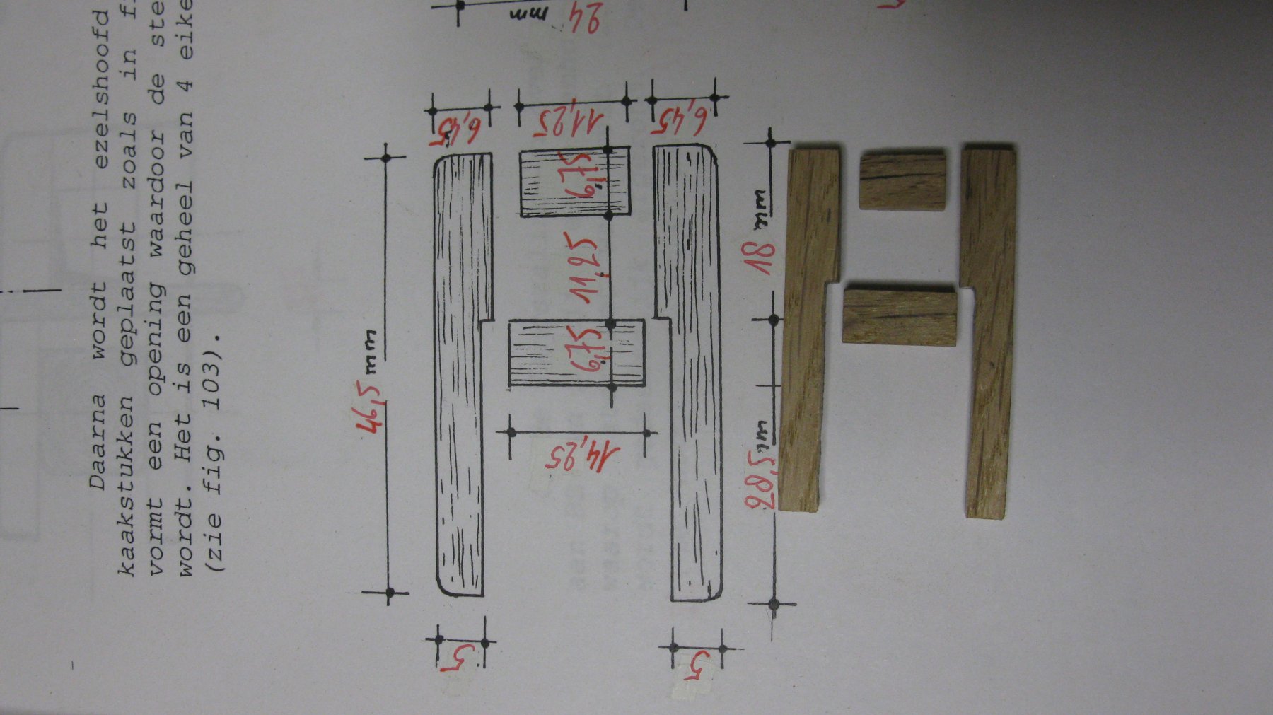
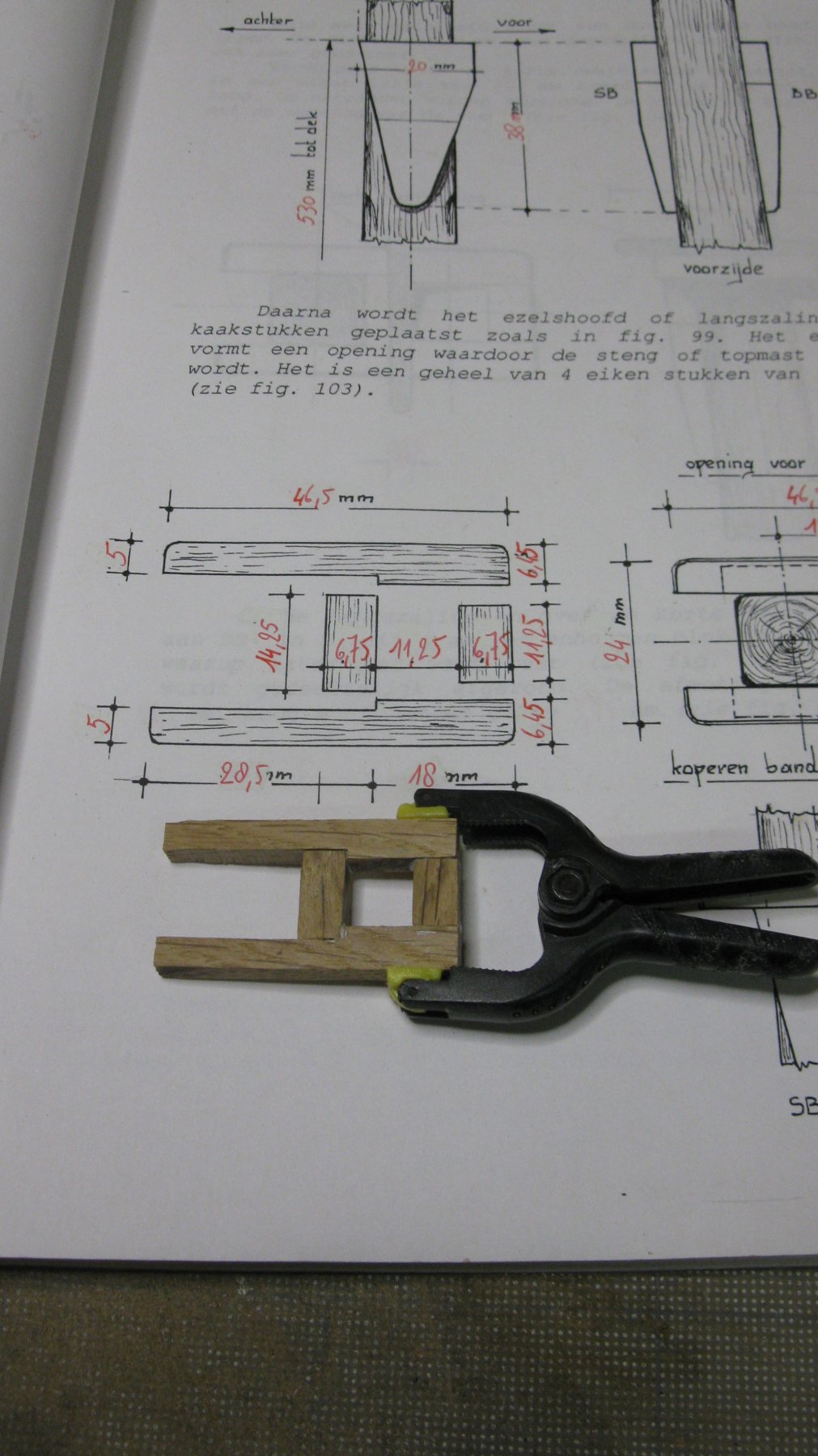
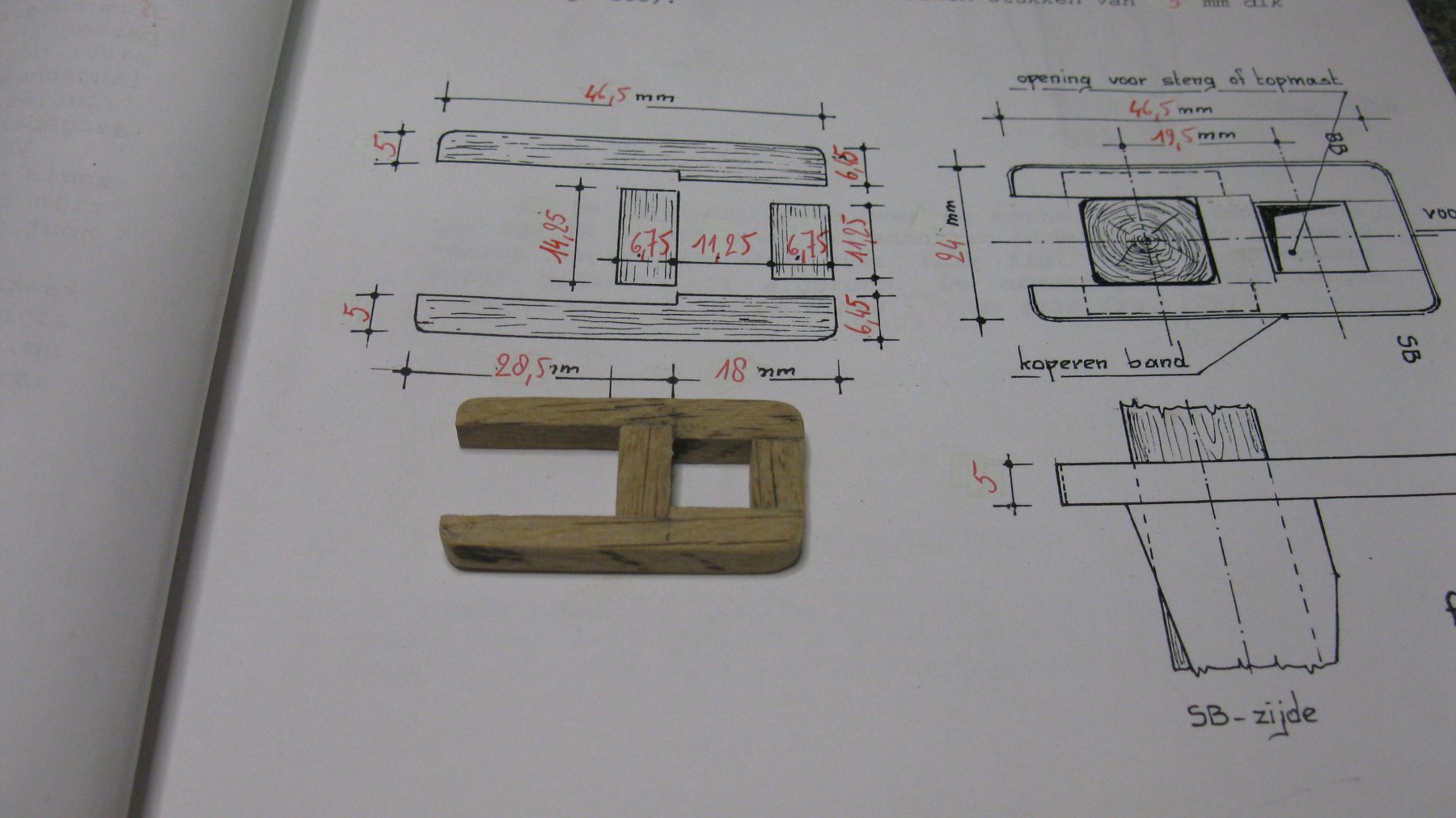
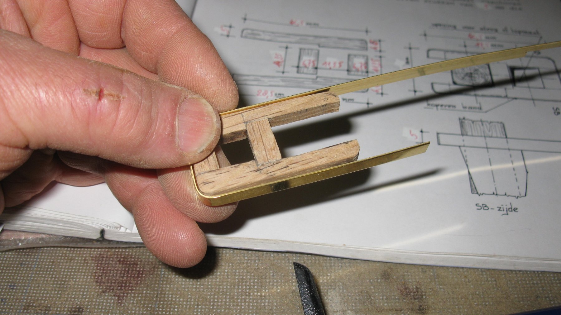
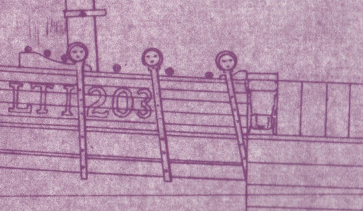
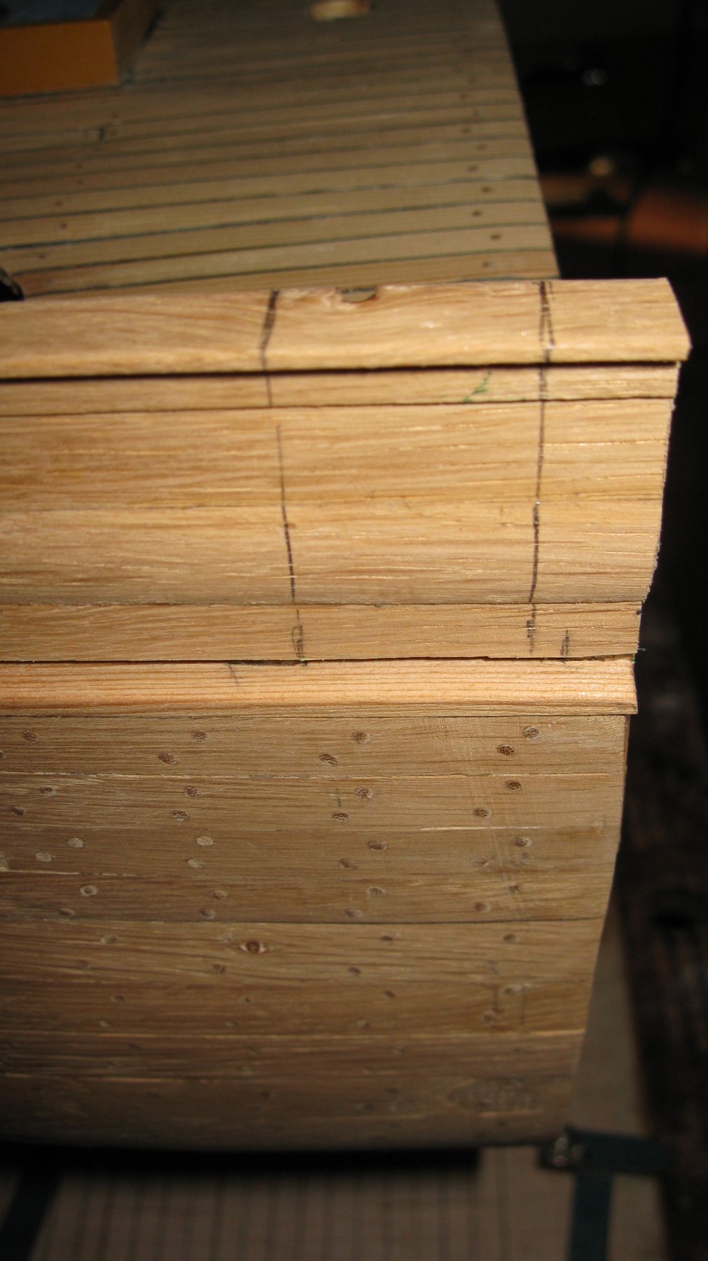
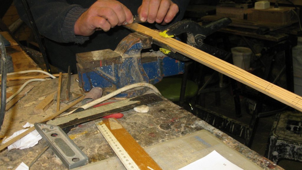
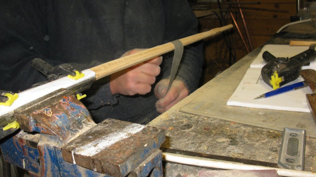
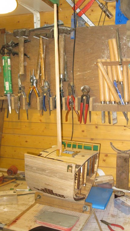
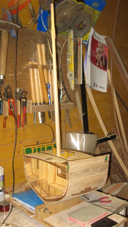
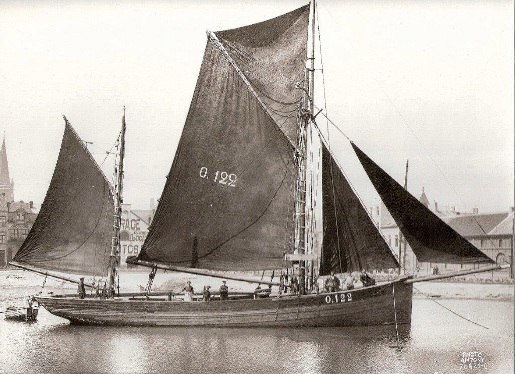
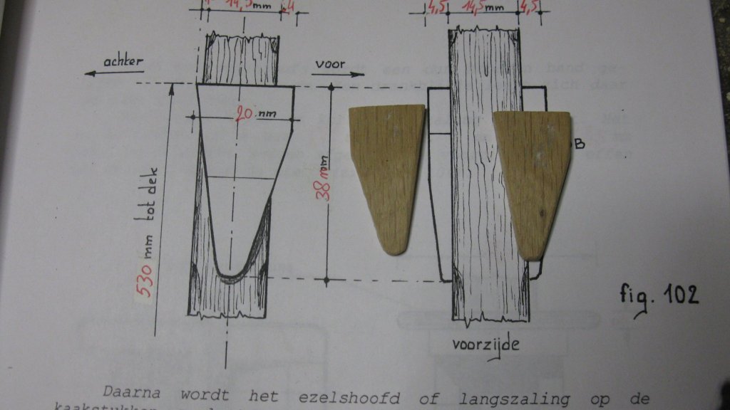
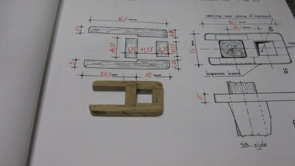
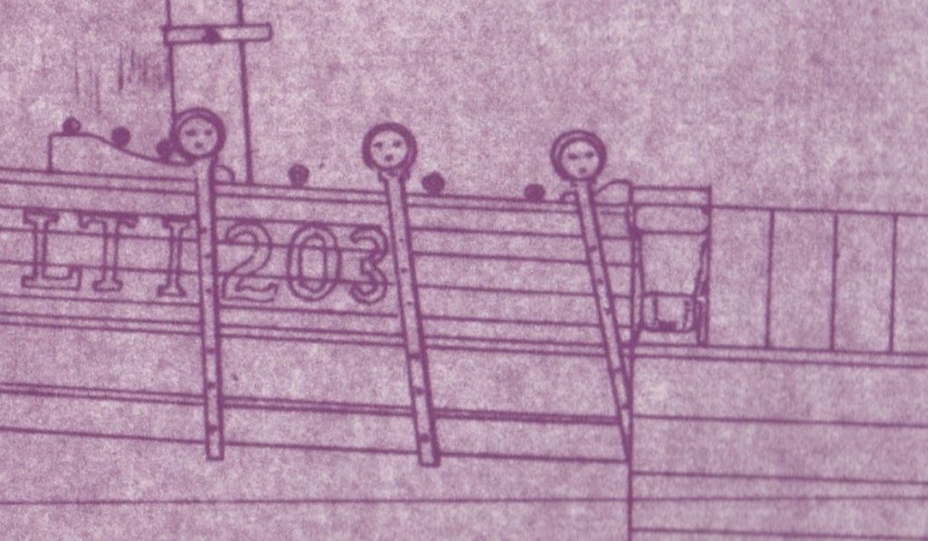
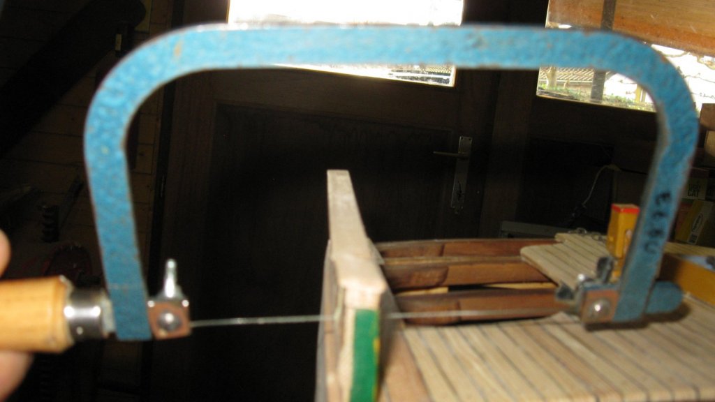
19. The spars. 19.1 The spars. Making the mast To make the mast, I start from a square pine stock. I narrow it towards the ends with the sanding belt. I then scrape the corners until I get an octagon. Next step is sanding the octagon to a round shape. The mast will keep its octagon shape from the mast step until about 6 cm above the deck and a square shape at height of the hound pieces. The mast on the cross section. It is leaning slightly forward just like on the real smack. (The picture of the smack O122 below belongs to Georges Verleene, the author of the practicum that I use to build this cross section. The helmsman on the picture is George's grandfather and the woman amidships his grandmother. In that era women did not sail on fishing vessels, the sails were probably hoisted especially to pose for this picture. You can clearly see that the vessel is moored. ) Making the hound pieces. Making the trestletrees and the crosstrees. Laying a metal band around the trestletrees. Gluing the trestletrees with the bolsters on the mast.


- 219 replies
-
- 12
-

-
- smack
- cross-section
- (and 2 more)
-
Thank you Pat. There is still some work to do: This week I will start to make the mast. That mast must also be rigged. The hull must be colored. I would like to make a work boat to store on the boat slide and last but not least the steam capstan has to be made. So enough to keep me busy for some more months.
- 219 replies
-
- 3
-
-
- smack
- cross-section
- (and 2 more)
-
That will become a very nice boat!
-
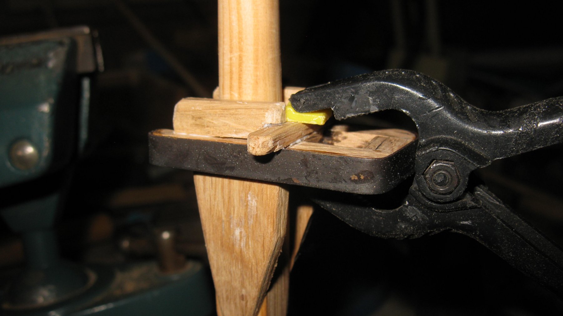
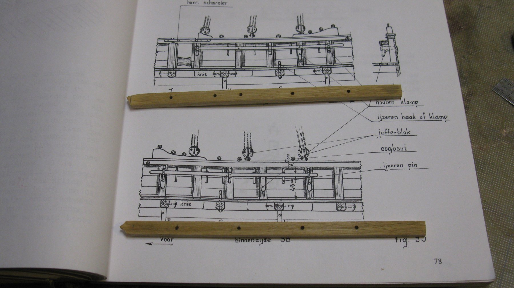
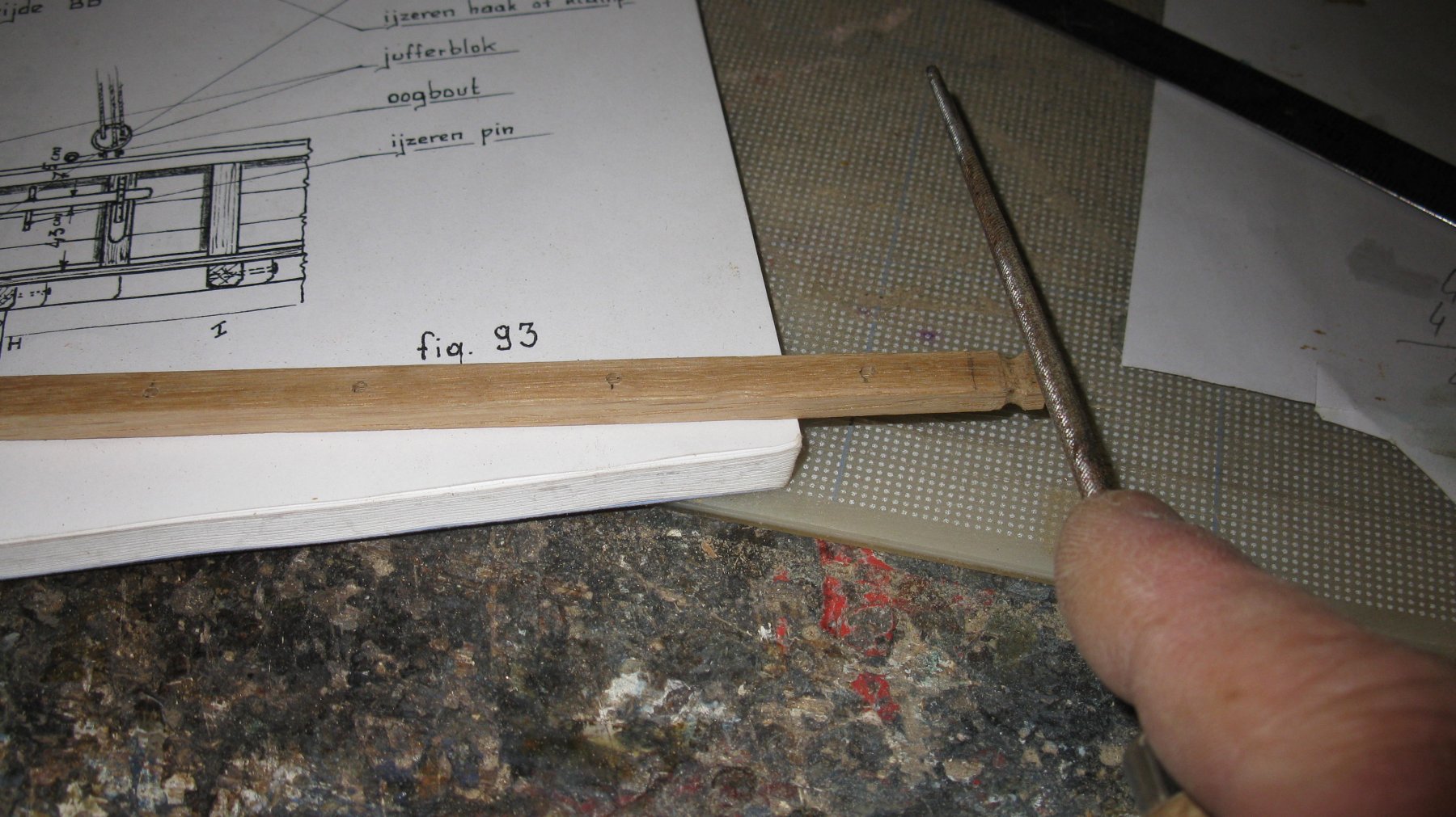
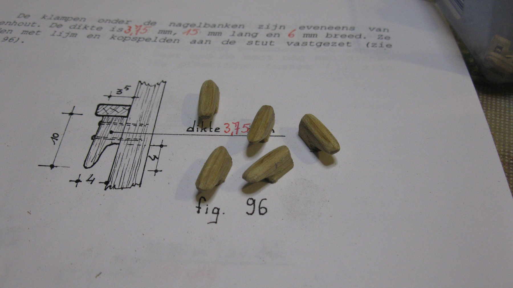
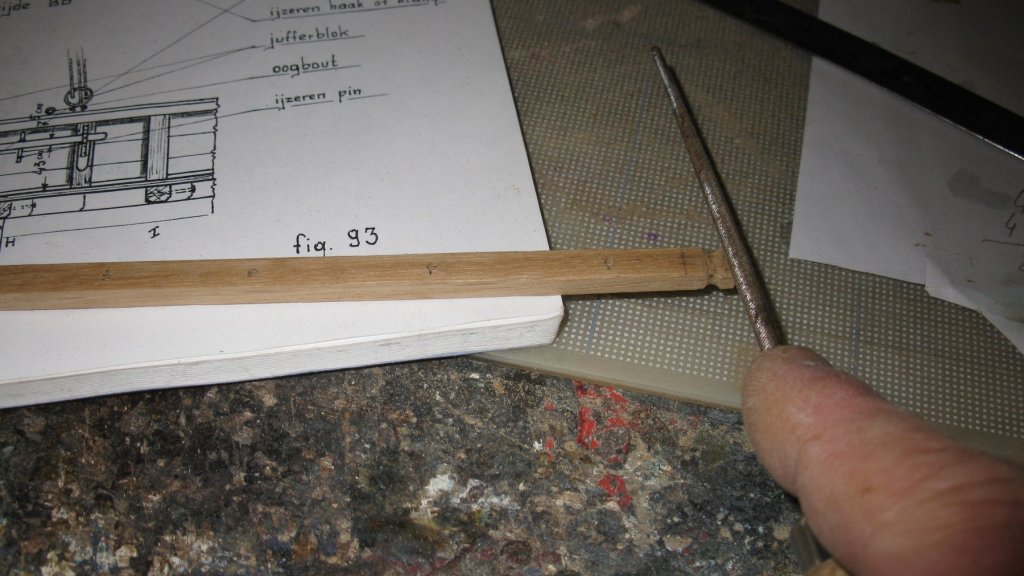
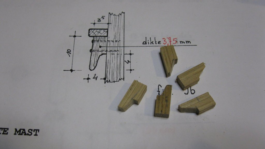
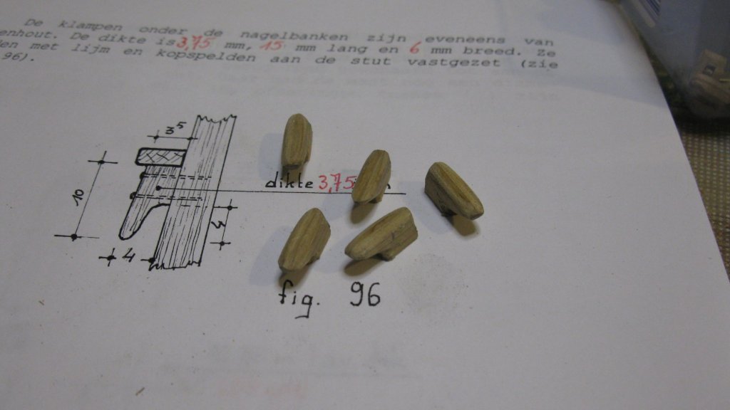
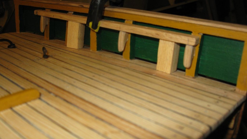
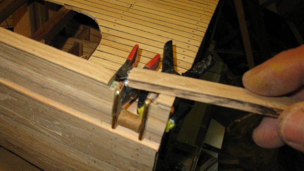
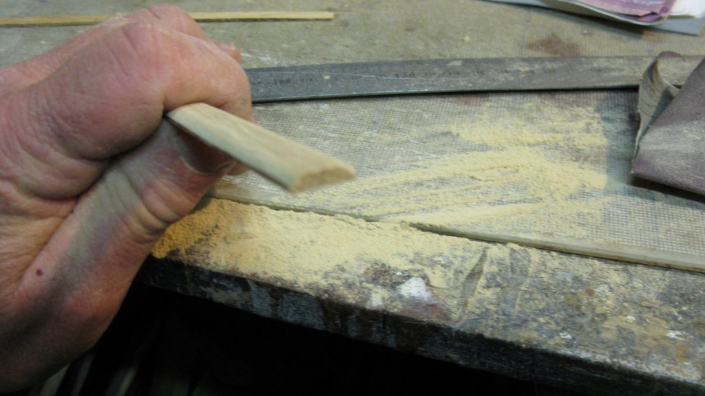
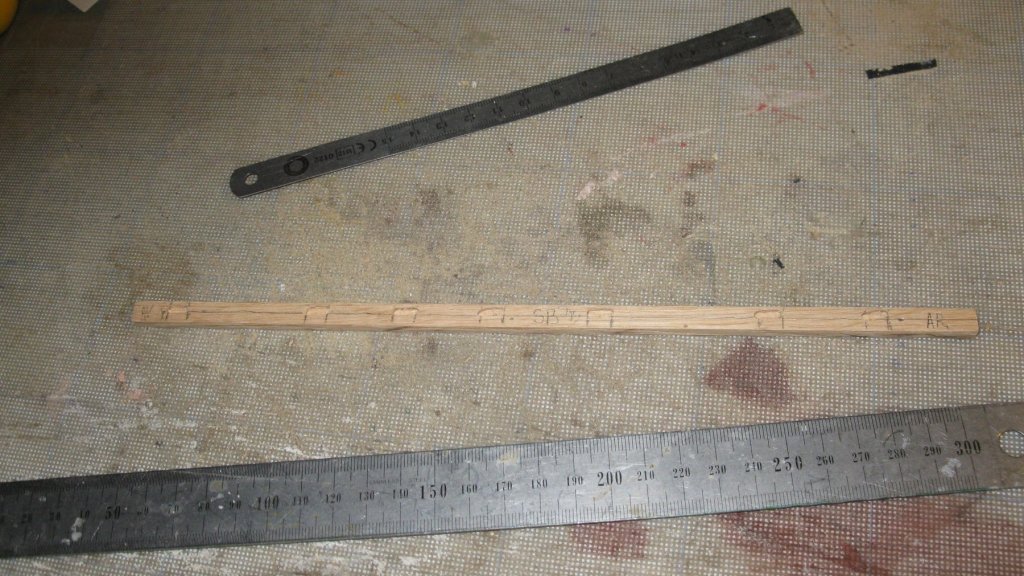
18.10. Deck finishing. Pin rails. At both sides of the cross section, there is a pin rail. I make them from two oak sticks. I shape the forward end of both rails with a round file. Making cleats for below the pin rails. Gluing the pin rails with cleats into place at starboard side. The rail is temporally laying on two wooden blocks to hold it at the correct height. And at port side.
- 219 replies
-
- 8
-
-
- smack
- cross-section
- (and 2 more)
-
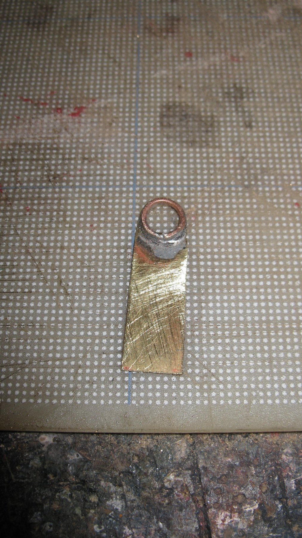
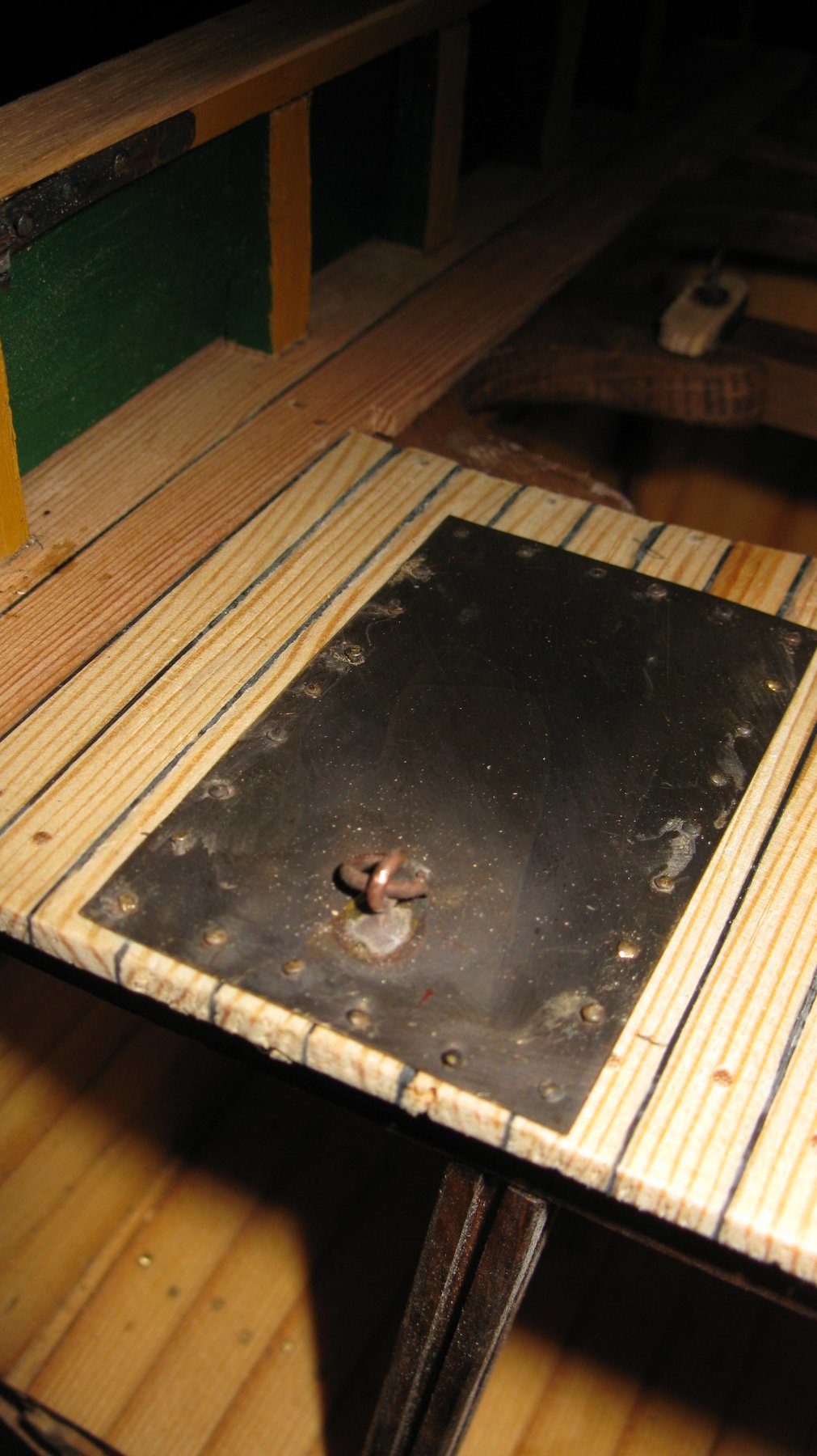
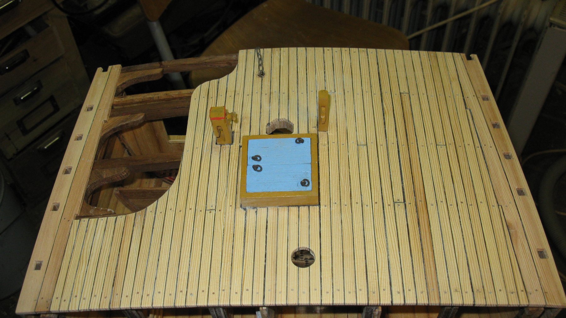
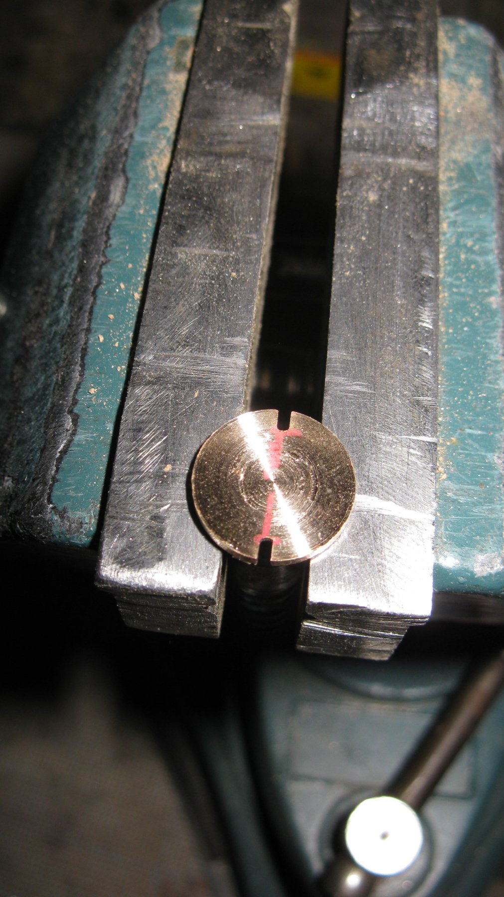
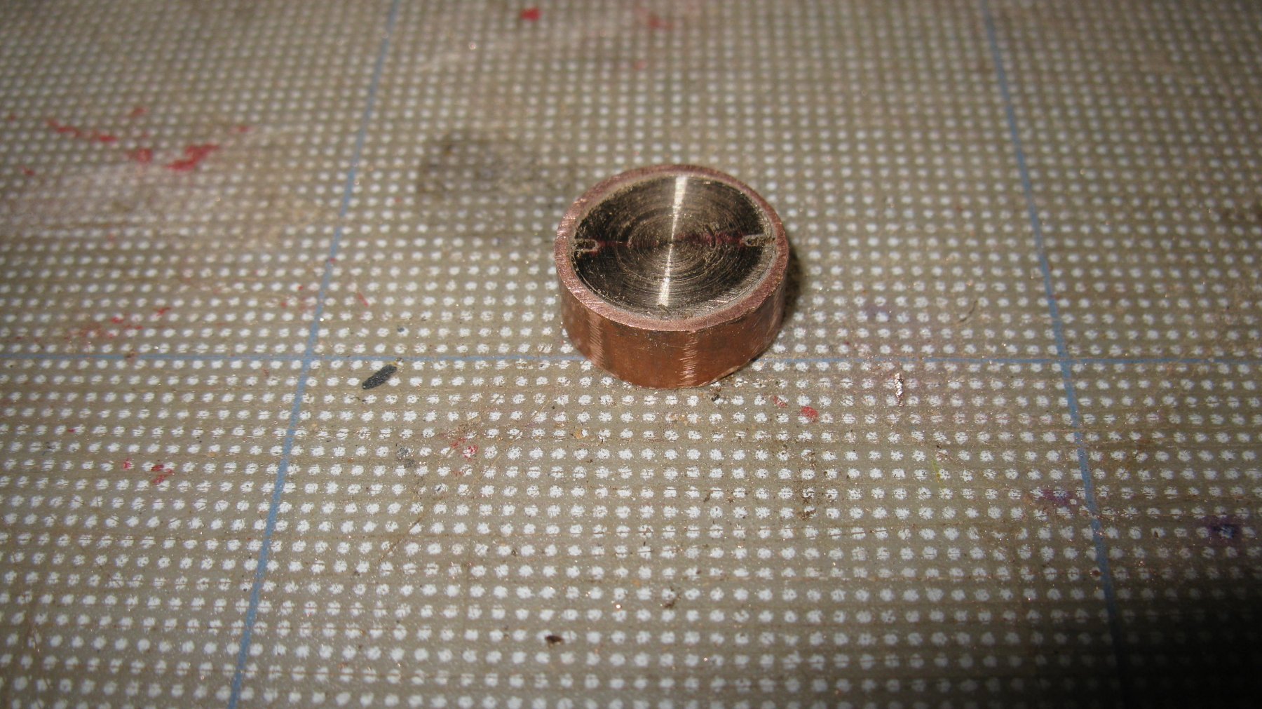
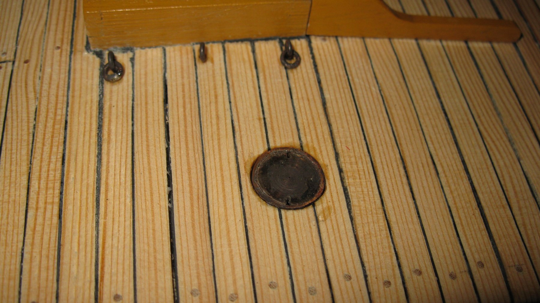
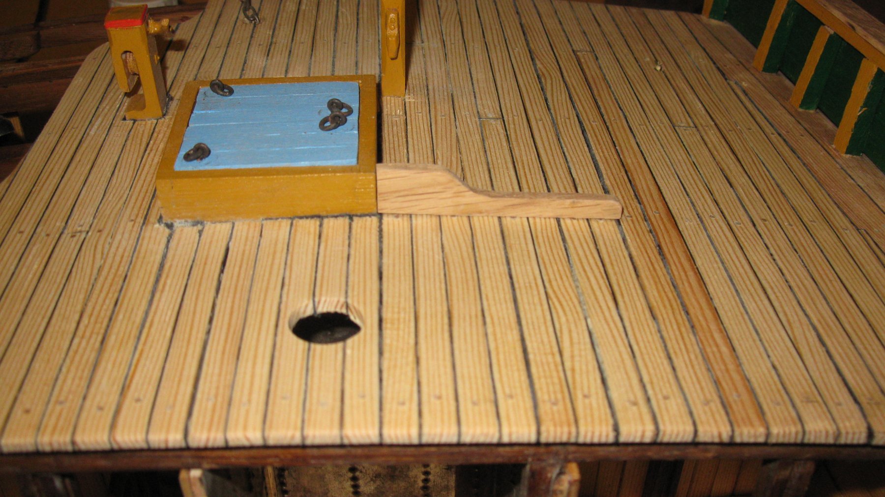
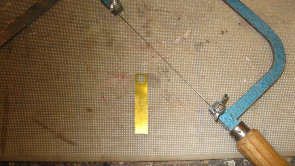
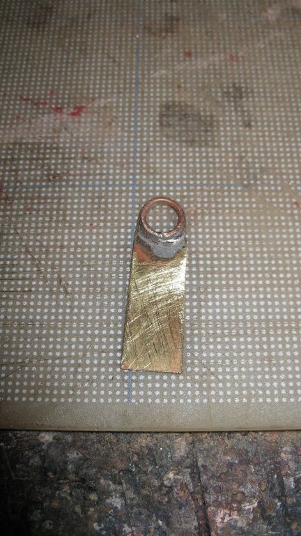
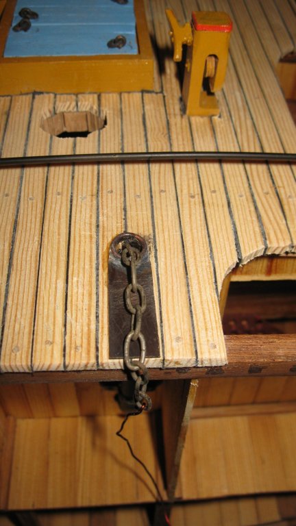
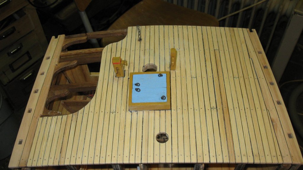
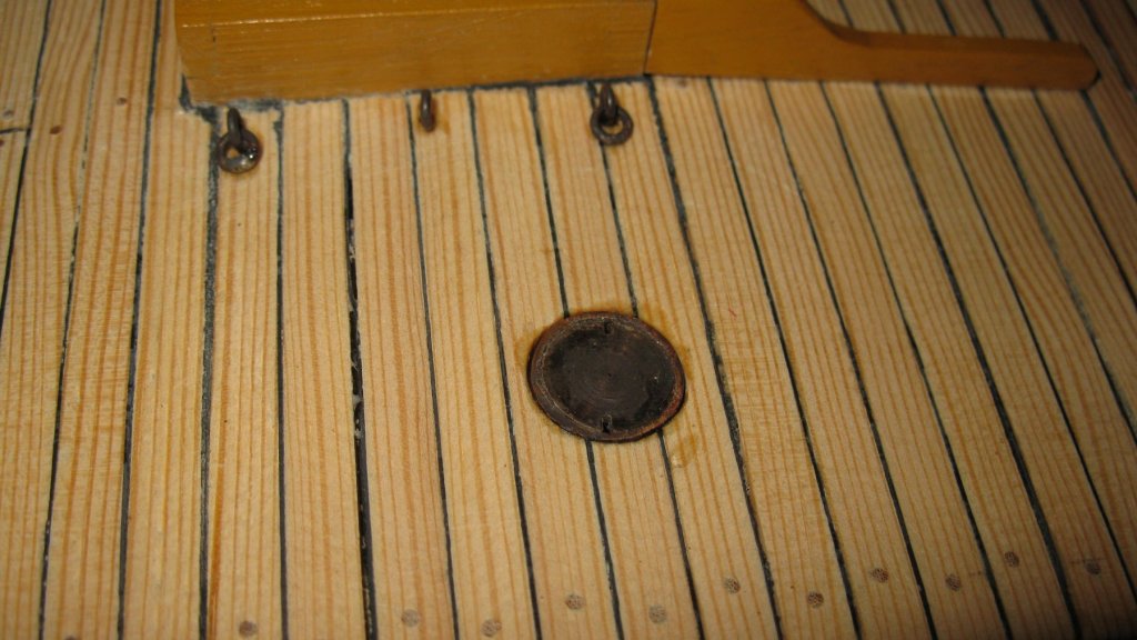
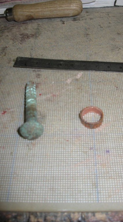
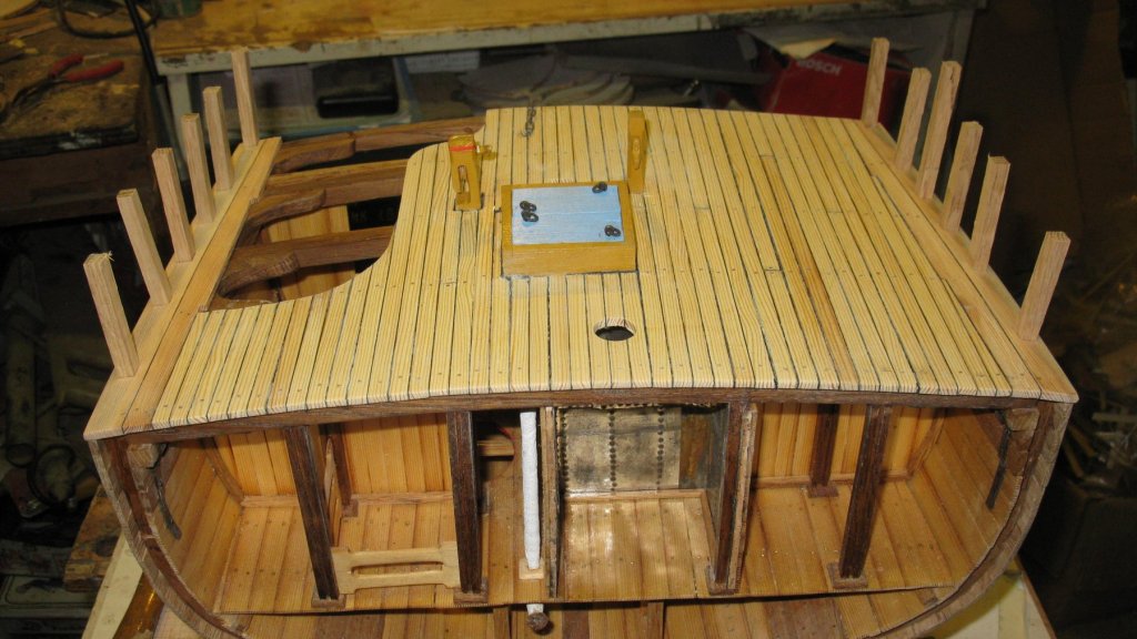
18.10. Deck finishing. Anchor chain pipe. I lay also a small protection plate for the anchor chain on the deck. A little bit outside of the edge of the cross section stands the anchor winch. The protection plate will also serve to secure my loose end of the chain. I saw the plate with a hole in it. ... solder a copper collar on it and saw and file the round end in shape. The plate is then blackened and glued on the deck.
- 219 replies
-
- 5
-
-
- smack
- cross-section
- (and 2 more)
-
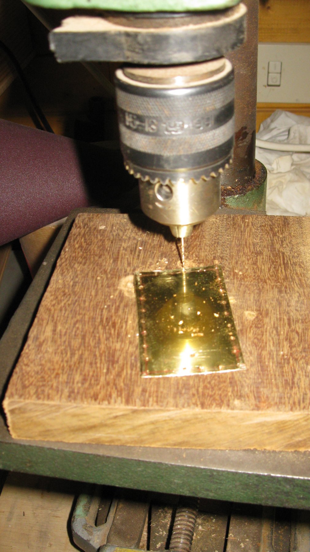
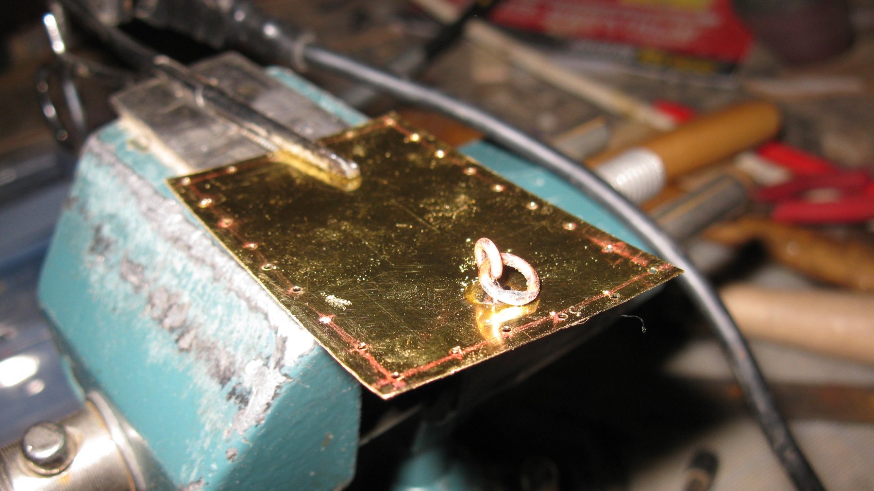
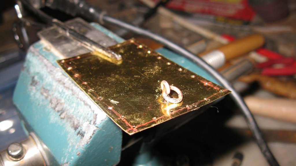
18.9. Deck finishing. Berthing for the trawl head. The deck of the smack is protected by an iron plate in the vicinity of the gate for the trawl rope. I cut a piece of brass plate for it and drill nail holes in it. A fastening ring to secure the trawl head is soldered on it. The plate, blackened and nailed on the deck.


- 219 replies
-
- 4
-
-
- smack
- cross-section
- (and 2 more)
-
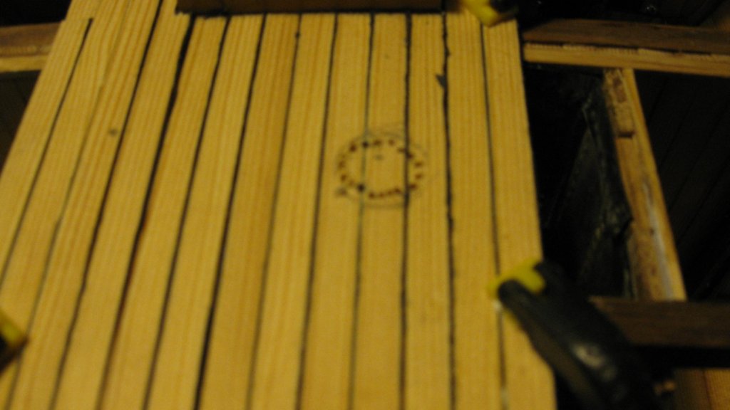
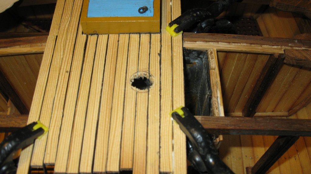
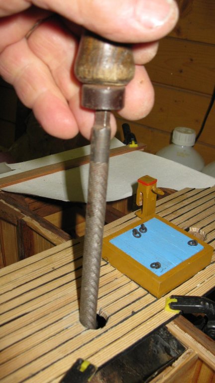
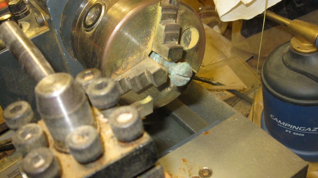
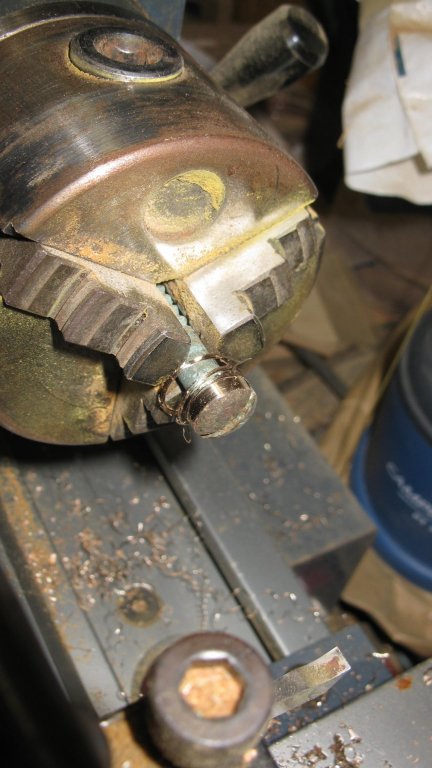
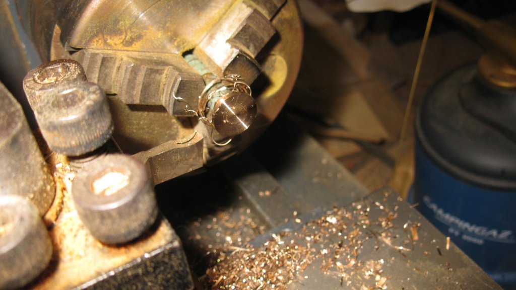
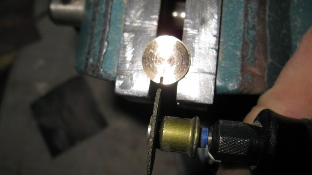
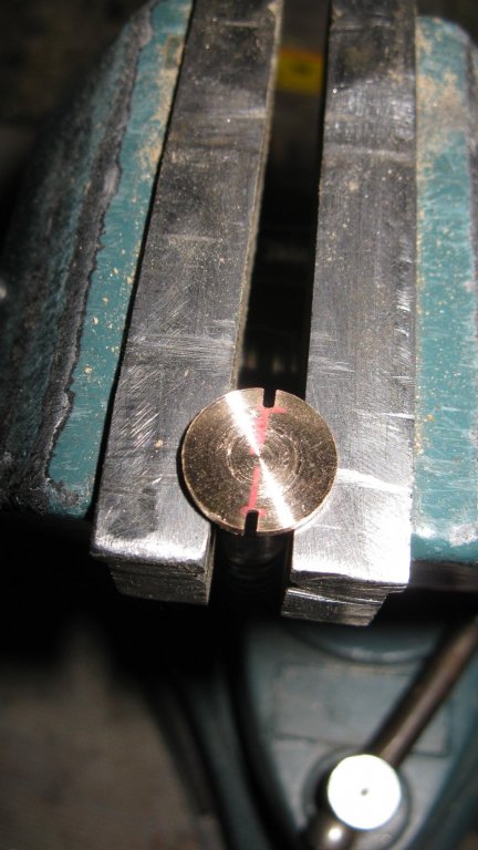
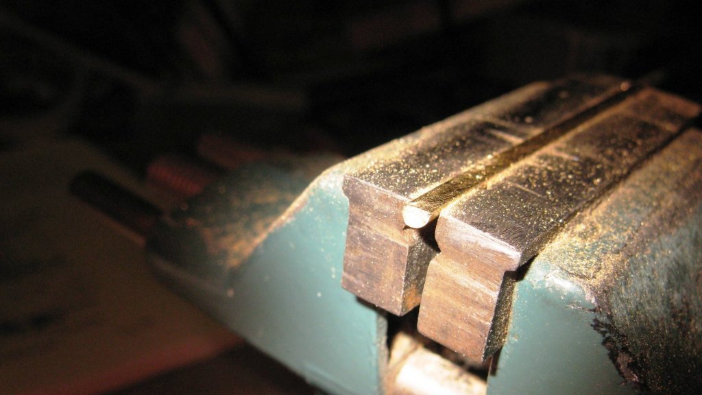
18.9. Deck finishing. Ice bunker cover. When I was laying the deck, I made a hole in it to place the cover of the ice bunker. The frame will be made of a slice of gas pipe and the cover of an old brass vise. Making the cover. The finished cover soldered in the frame... ... and glued into place after being blackened.

- 219 replies
-
- 12
-
-
- smack
- cross-section
- (and 2 more)
-
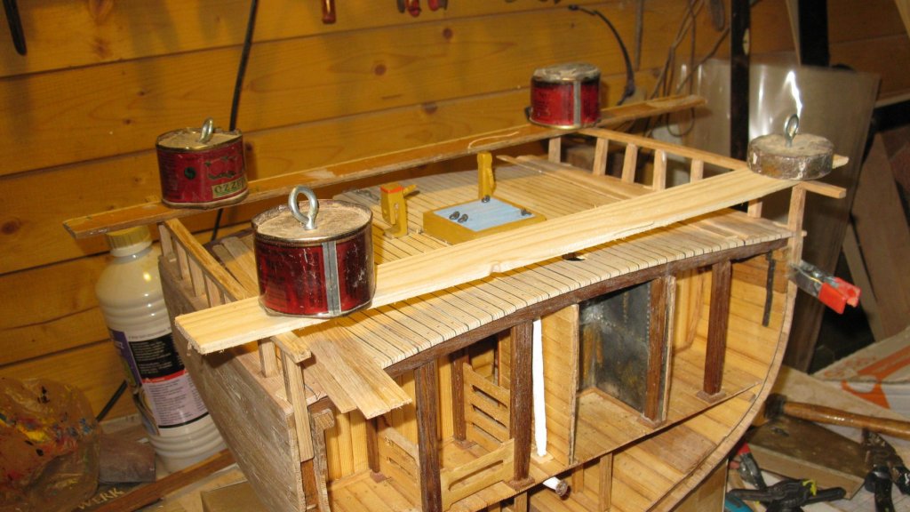
18.8. Deck finishing. Boat slide. Right of the hatch there is a slide to support the ship's boat. Fitting the slide. Slide glued into place after being painted and varnished.

- 219 replies
-
- 3
-
-
- smack
- cross-section
- (and 2 more)
-
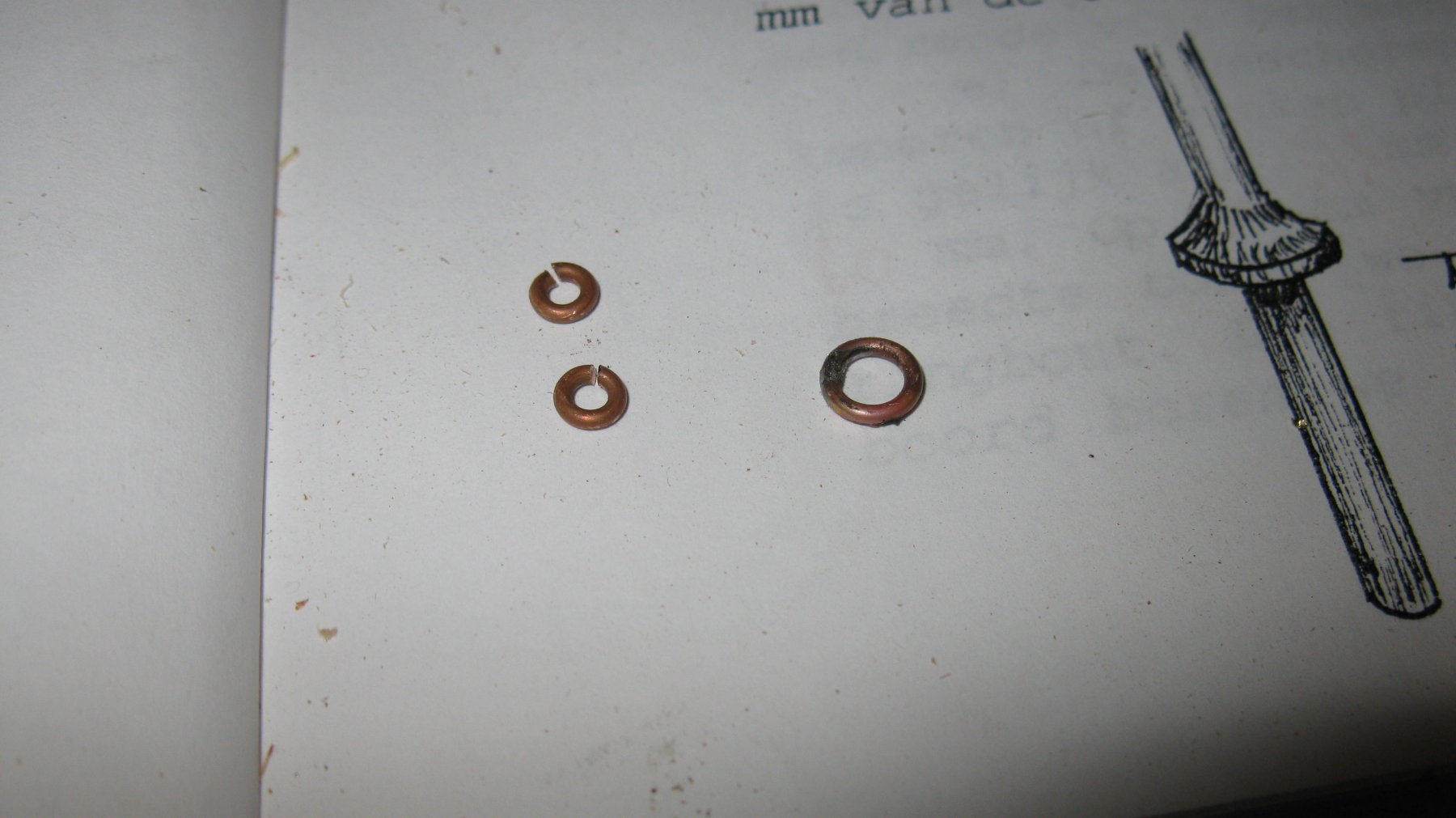
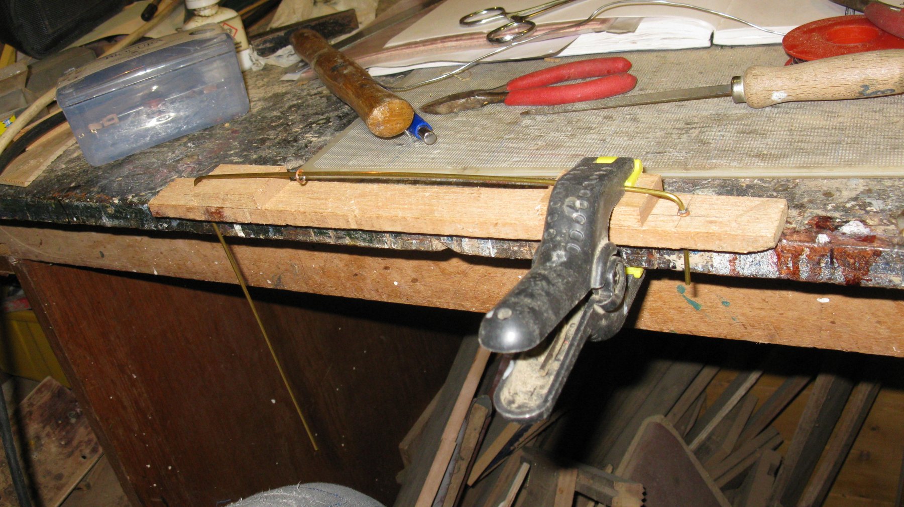
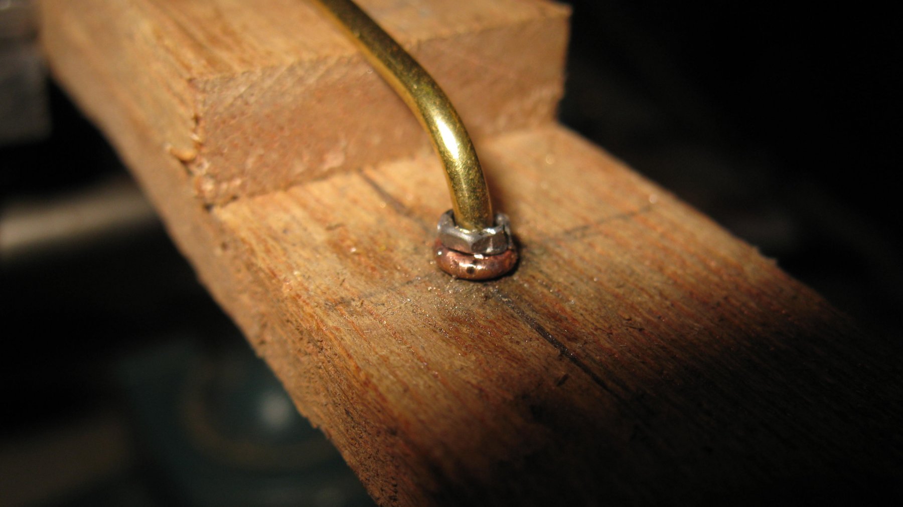
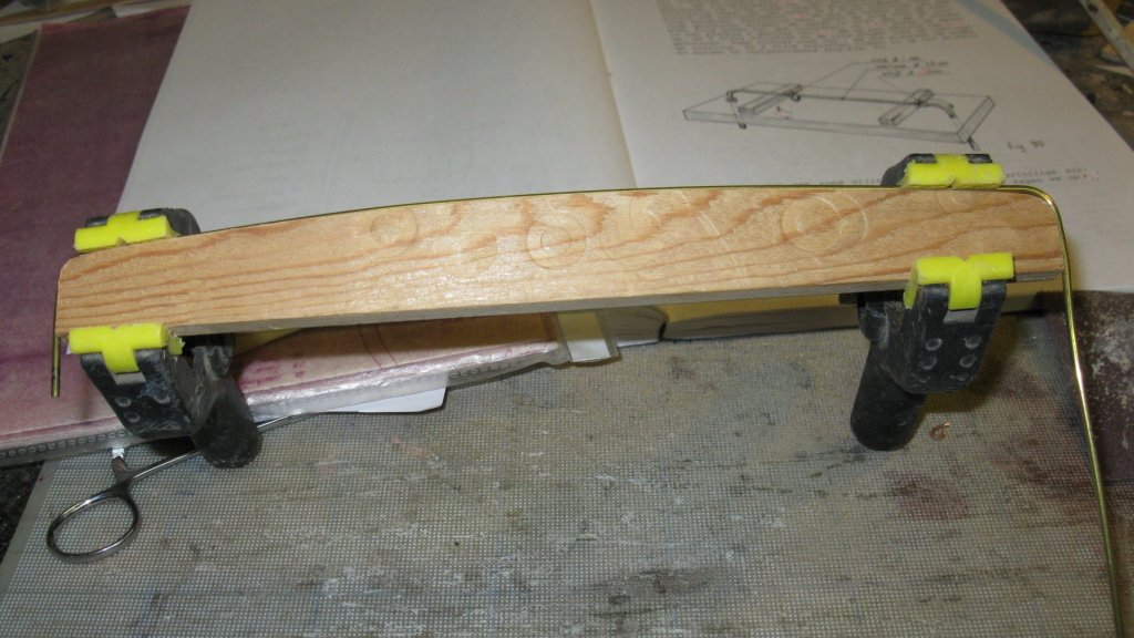
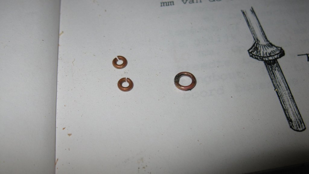
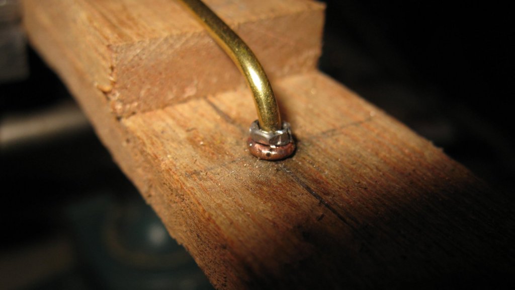
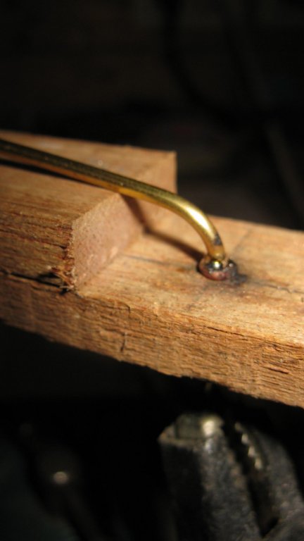
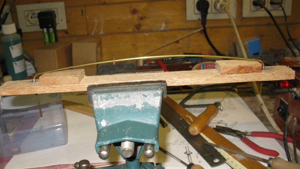
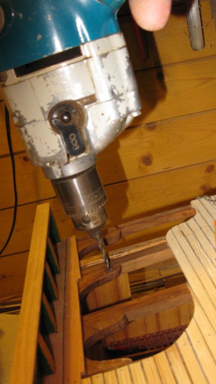
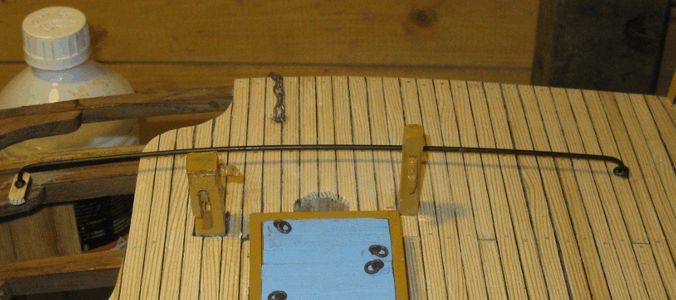
18.7. Deck finishing. The traveler for the jib sheet. To make the traveler , I bend a 2mm brass tube round a wooden template to give it the right shape. I make three rings of copper wire. The large ring, outer ø 6mm, goes around the traveler to hold the jib sheet block, the two small rings, inner ø 2mm will form the traveler feet. To make the traveler feet at the correct height I use a simple wooden jig. A bit solder tin round the traveler ... ... then heating with the soldering iron and filing it. Drilling the mounting holes. and placing the traveler after it has been painted black.

- 219 replies
-
- 3
-
-
- smack
- cross-section
- (and 2 more)
-
Michael, I admire your patience. How many lamps will you make before you are satisfied with the perfection?
-
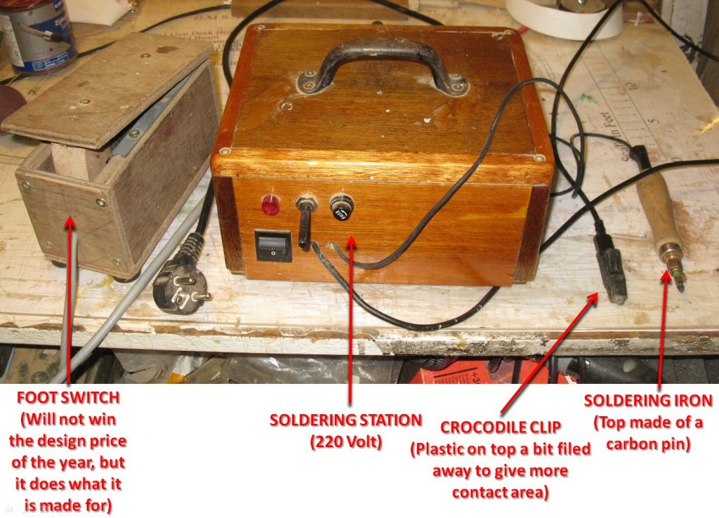
My first soldering iron was made with a carbon rod from a battery, but afterward I got some rods of purified carbon with a thin copper shell which I use now in my soldering iron. They are thinner, less fragile and probably the small amount of fume which is released while soldering is less unhealthy.
- 219 replies
-
- 2
-
-
- smack
- cross-section
- (and 2 more)
-
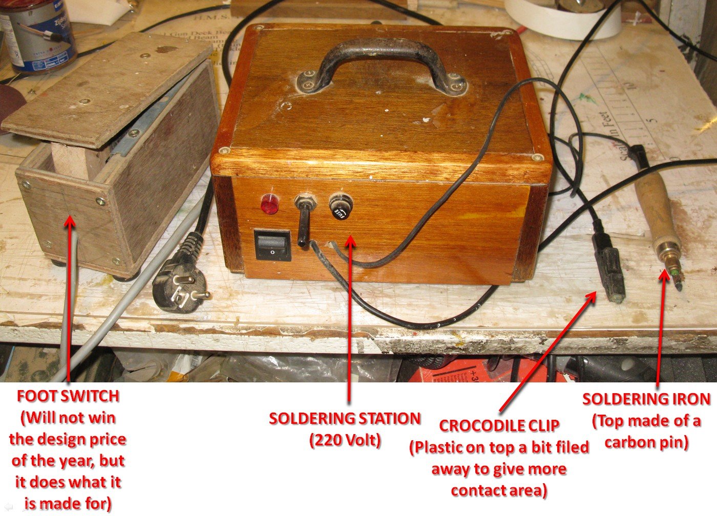
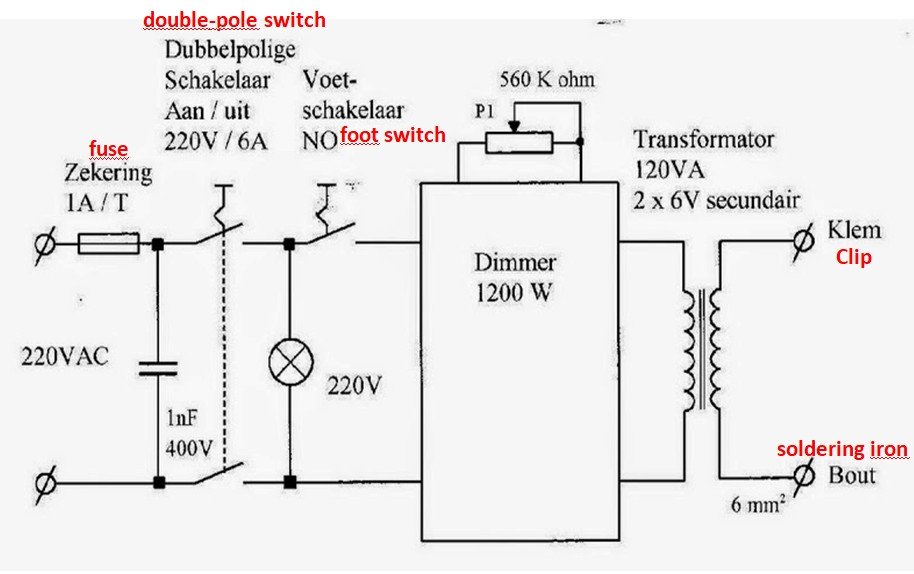
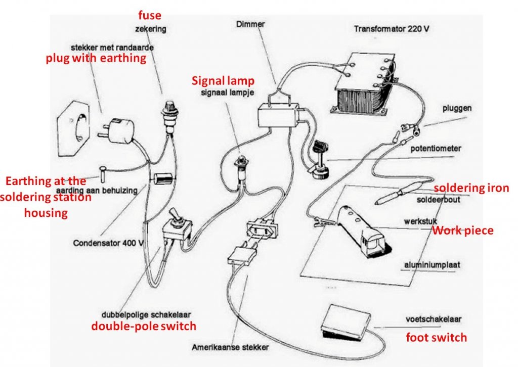
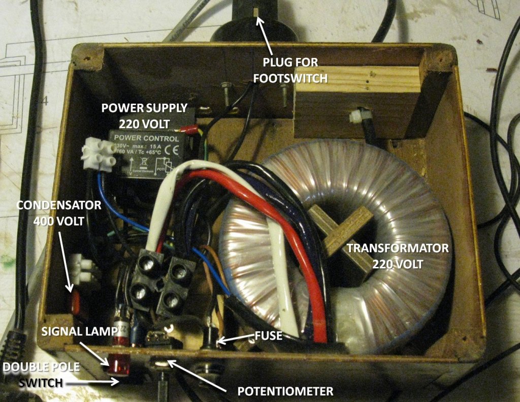
Well Michael, Now you bring me some embarrassment. My soldering station is not a technical masterpiece, but it is a self fabricated apparatus. When I started to make ship models, I did not succeed in soldering well. Some years ago we had a demonstration in our modeling club about resistance soldering and seeing that, I had my eureka moment. That was the soldering method that I needed! The fellow who demonstrated had a commercial built soldering station that was quite expensive and it was not available for purchase in Belgium but he said that it could be built relatively easy by yourself. So I started to search on the internet. My technical English is not sufficient to explain the resistance soldering technique in an intelligent way so I refer to this website for more information: Resistance soldering To build my station, I used following diagrams (source: Cooltrain.be): For a techno-illiterate like me even the above diagram is a mystery, so I used the scheme for dummies (source: Cooltrain.be) below: It gave me the necessary information to buy and search all the needed components and to fabricate my soldering station. That is like it looks inside. Now I am able to solder as well. But I am still far from making a navigation light like you are doing for your skipjack. The main advantage of resistance soldering is that there is a intense heat produced in a fraction of time at the carbon point of the soldering pin. It allows to solder in the close vicinity of other soldered parts without melting those other parts loose.
- 219 replies
-
- 13
-
-

-
- smack
- cross-section
- (and 2 more)
-
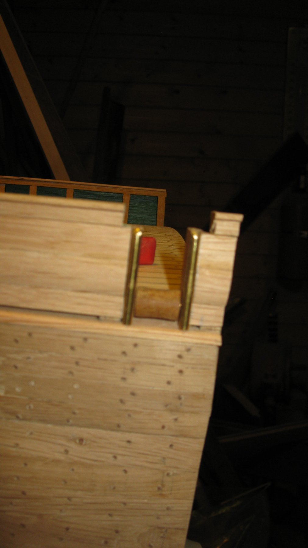
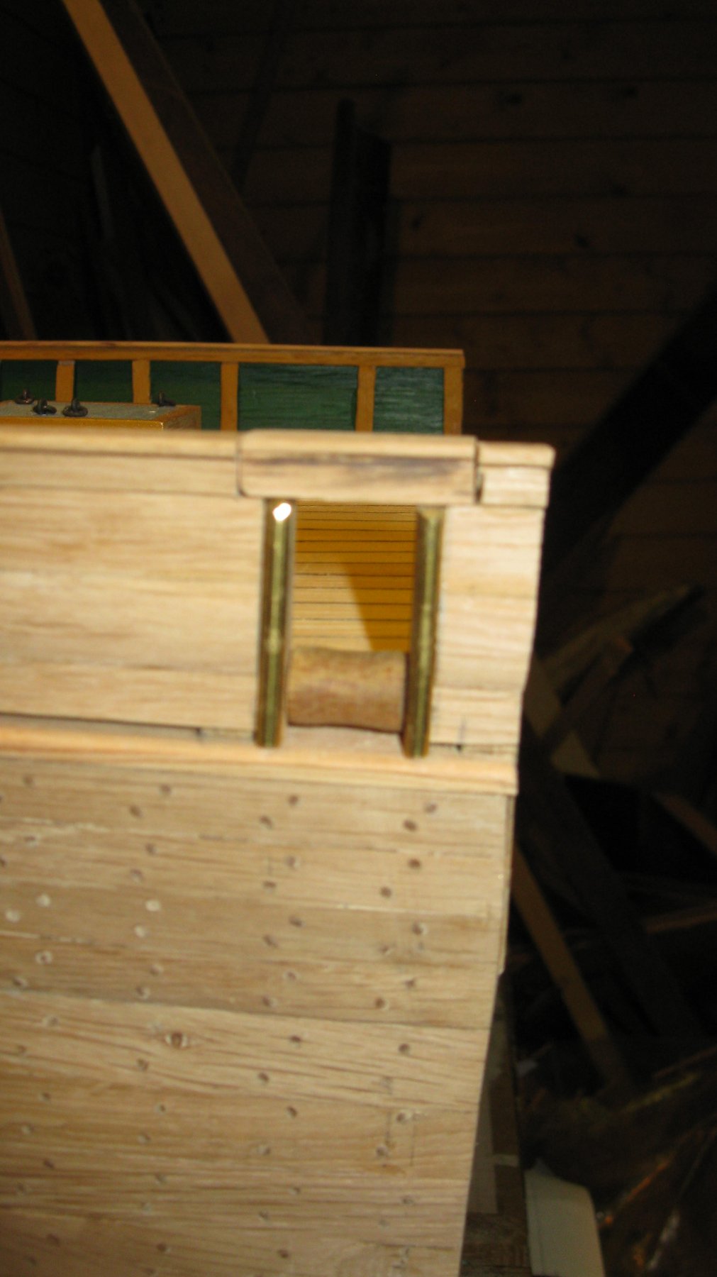
Thank you Carl, What you mention makes sense. I think that the reason for a inward flipping is that the hinge must be on top of the cap rail if flipping upward. There is still some stuff to be placed on the cap rail which leaves no room for a hinge forward of the gate. The hinge could be placed aft of the gate, but that part is not included in the cross section. Maybe it was there in reality but the author of the practicum used the 'poetic freedom' to place it on the side to make a cross section with flipping cap rail possible. Who knows...
- 219 replies
-
- 1
-
-
- smack
- cross-section
- (and 2 more)
-
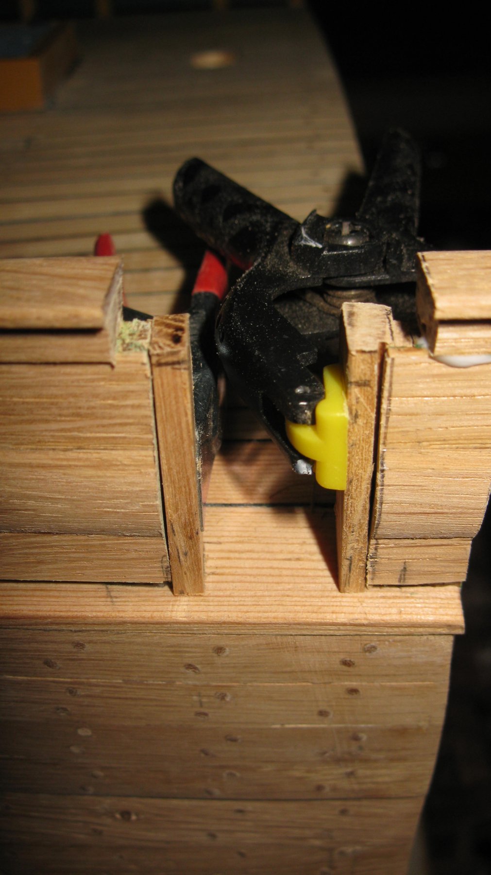
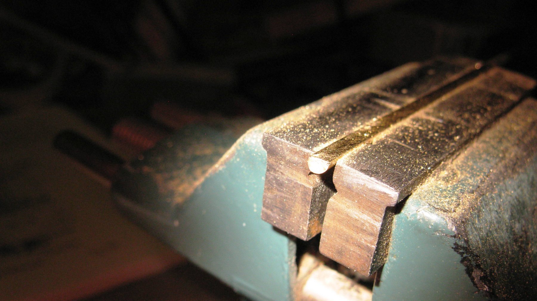
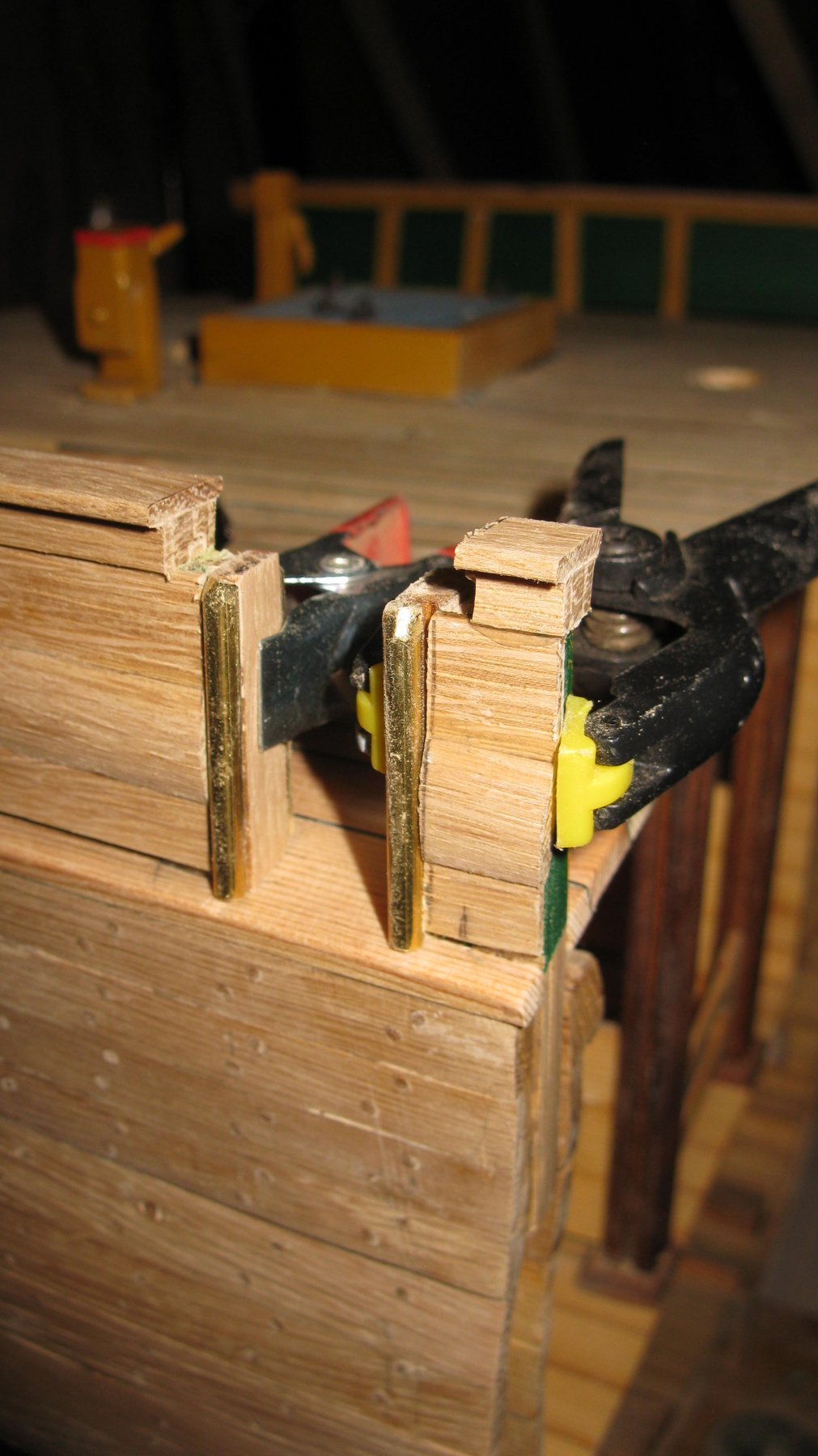
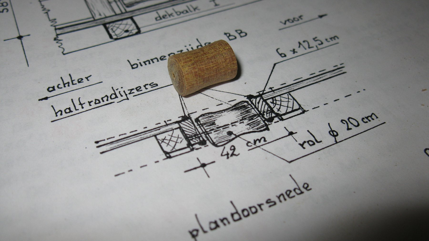
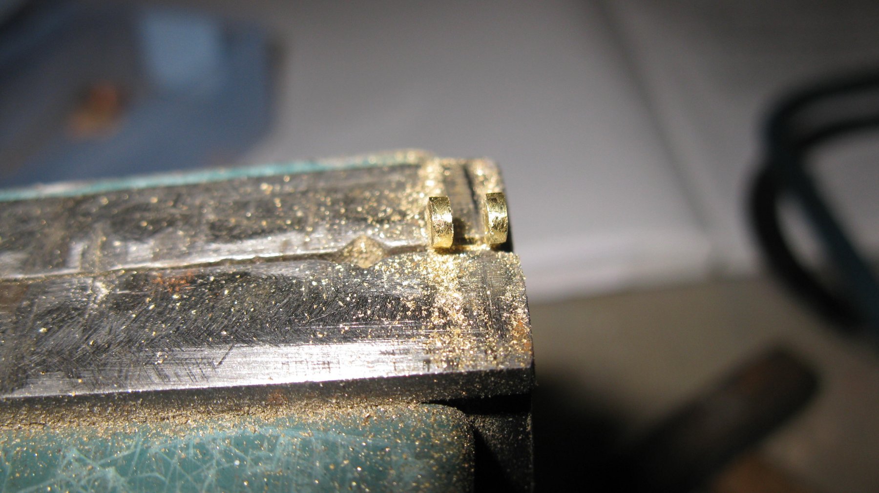
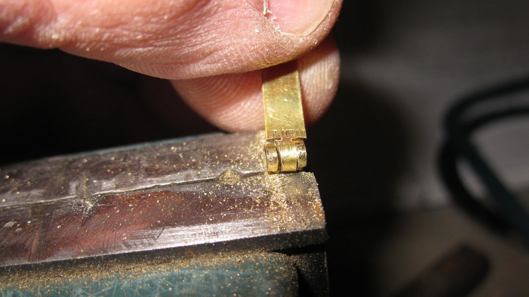
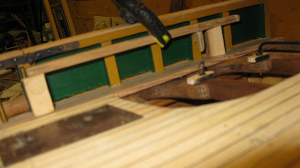
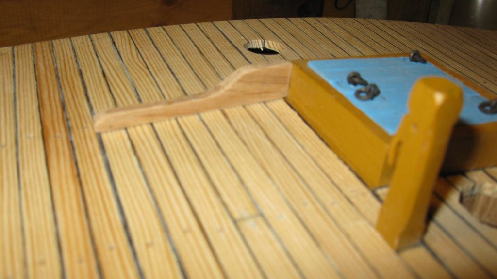
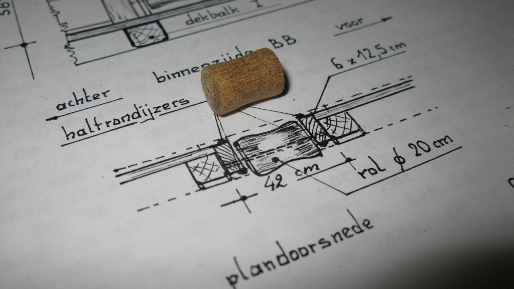
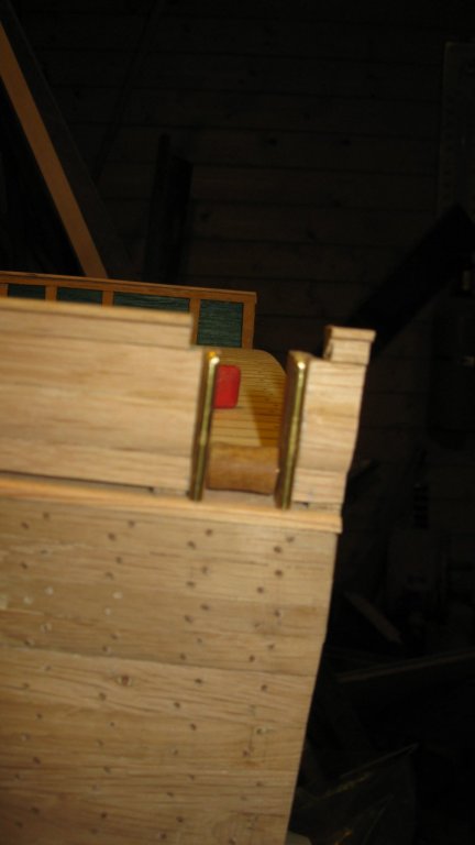
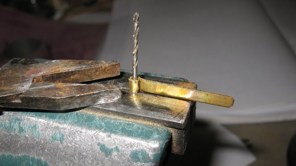
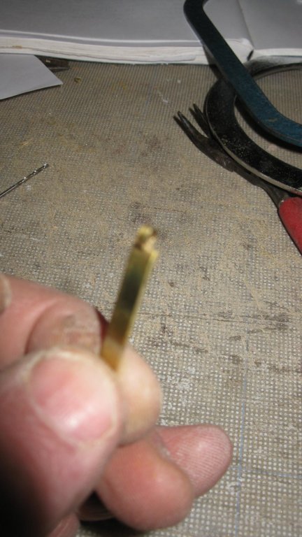
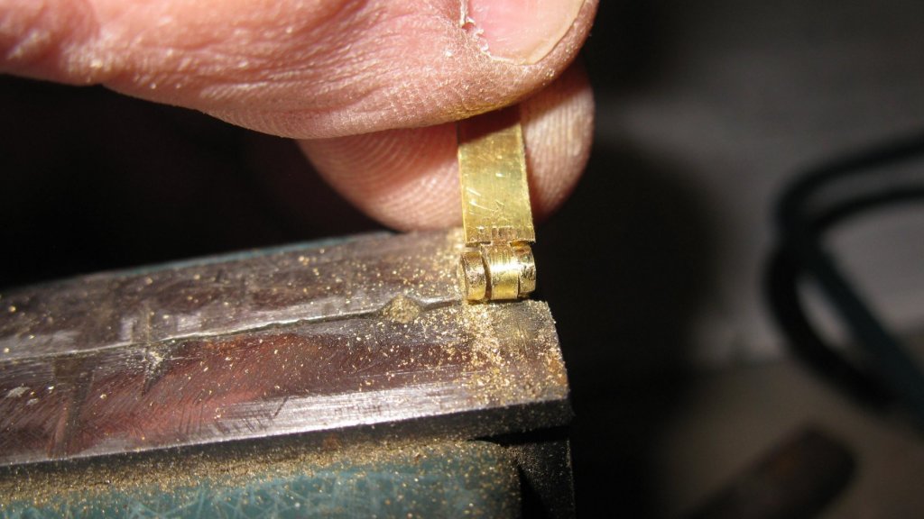
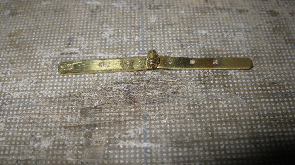
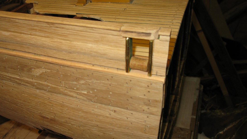
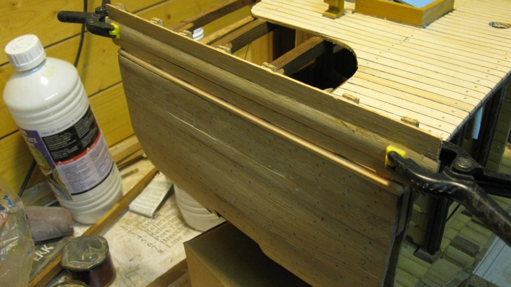
On port side there is a gate for the trawl warp. I saw the opening for it. Placing the side frames. The side frames are protected for the scraping of the warp by half round iron bars. I make the half round bars by filing half of a brass 2mm ø rod. The roll for the gate. Taking measurement for the hinged part of the railing. To make the hinge I saw two strips of brass and bend one end of them around a 1.5mm drill. I file the outsides of the loop from one of the strips (apologies for the blurry picture). I saw away the middle of the loop of the other strip. The two together form the hinge. The gate


- 219 replies
-
- 11
-
-
- smack
- cross-section
- (and 2 more)
-
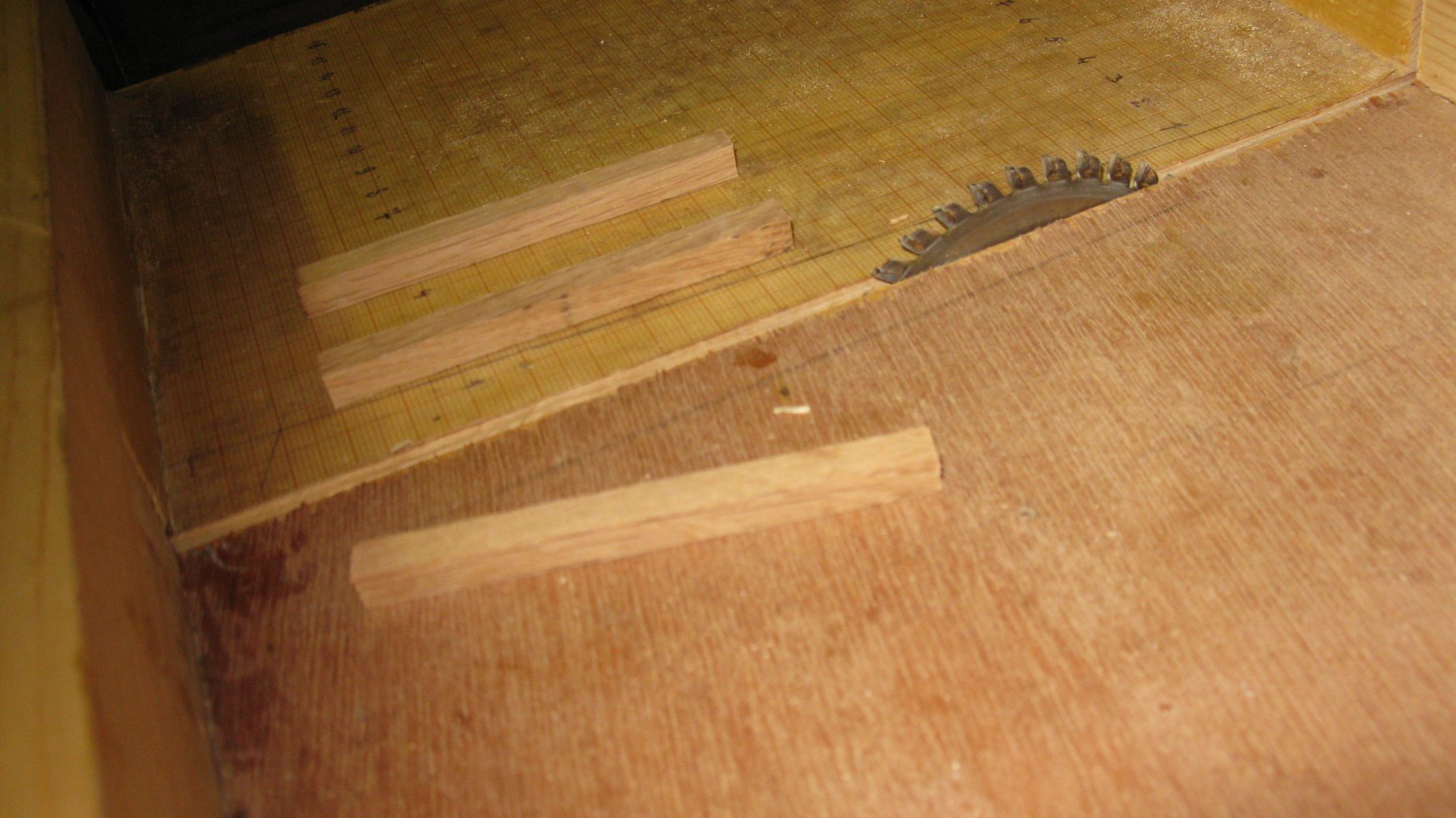
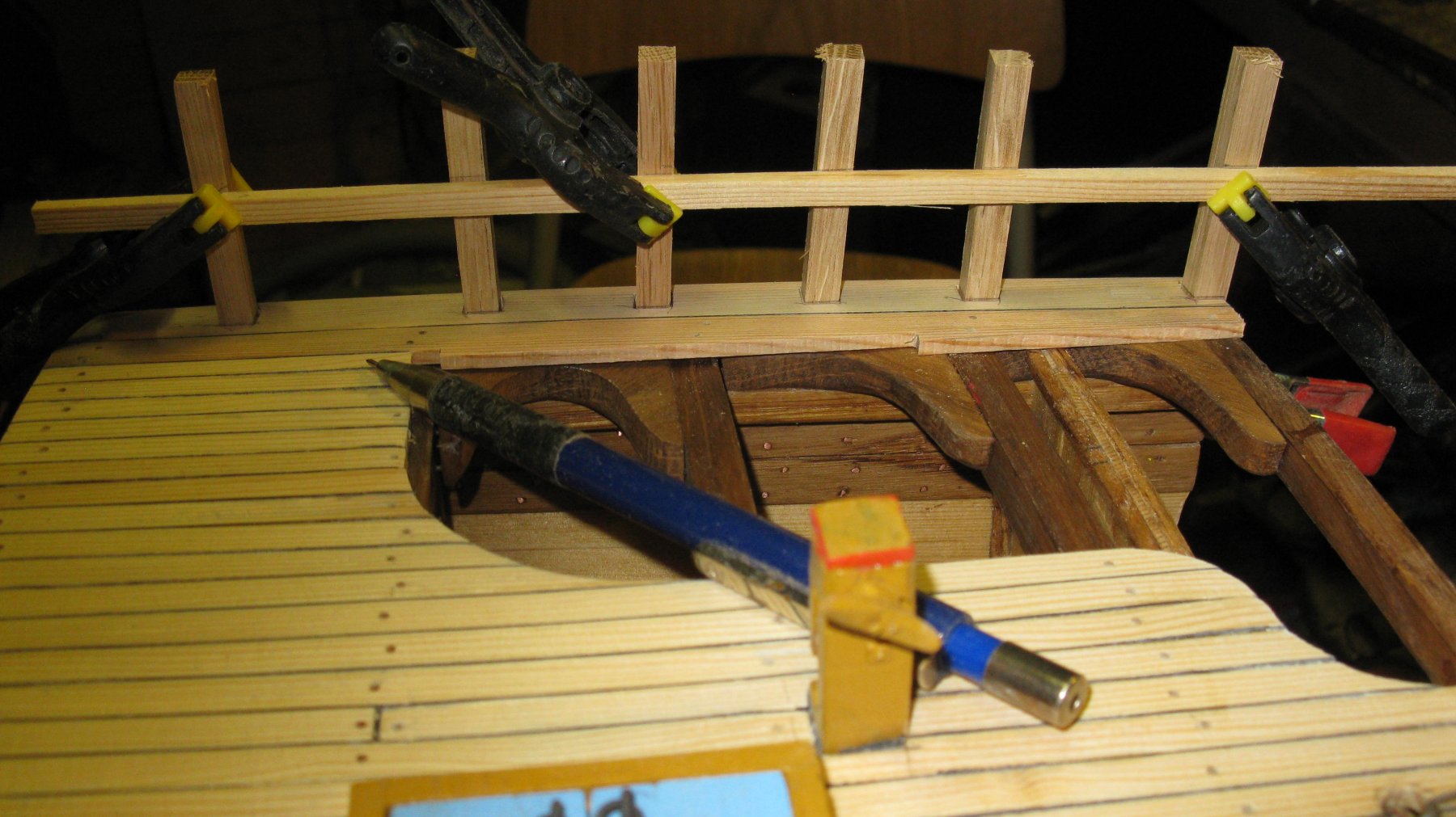
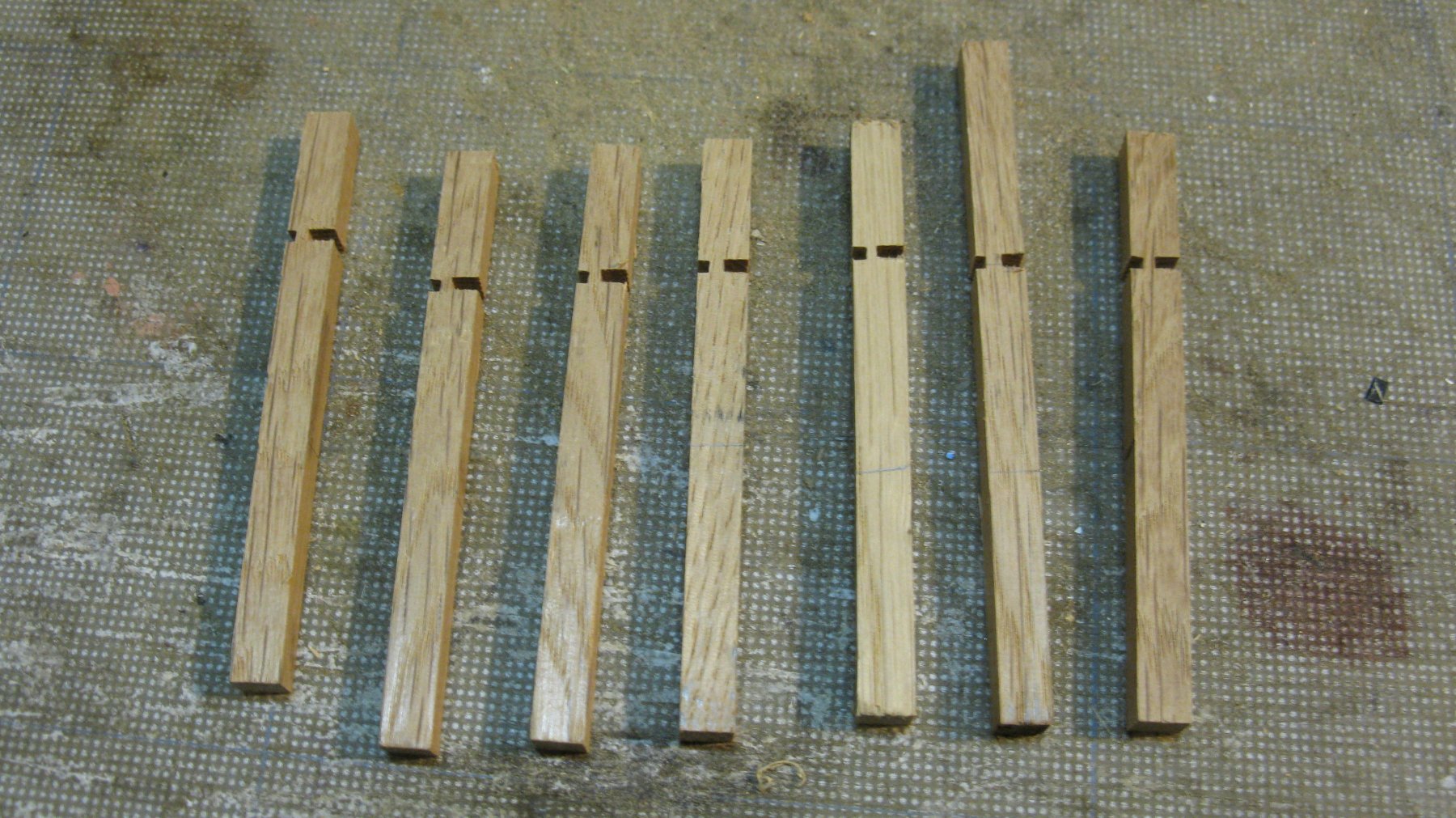
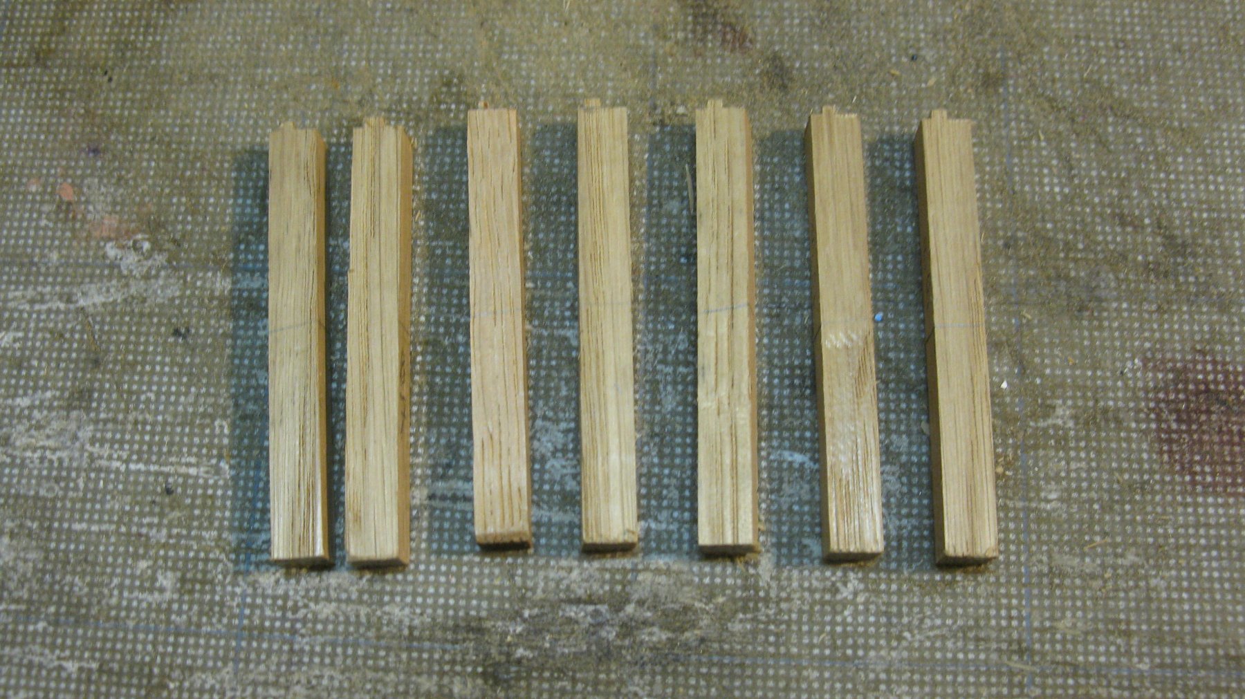
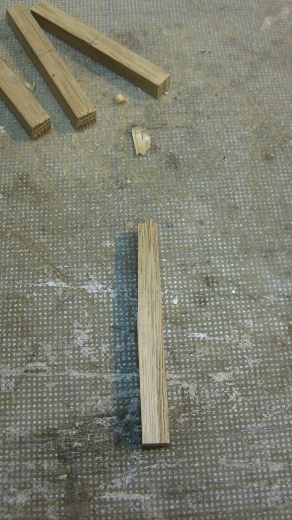
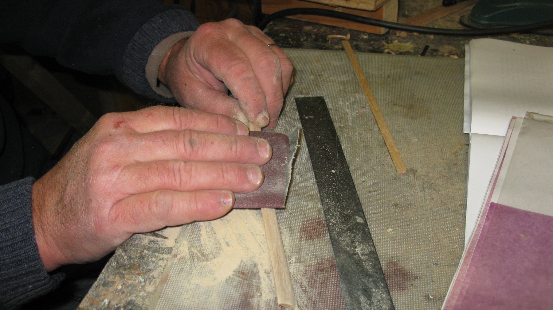
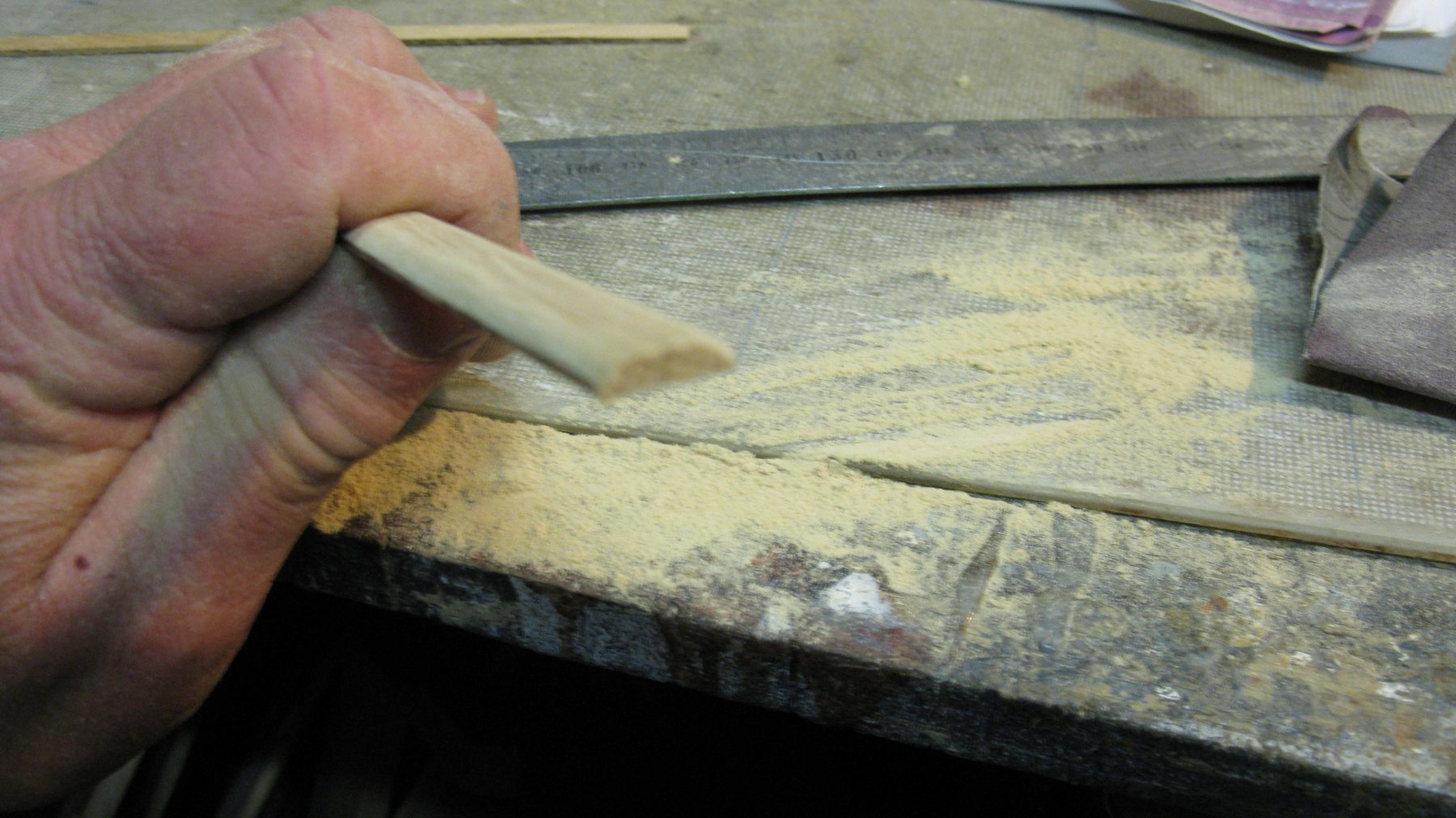
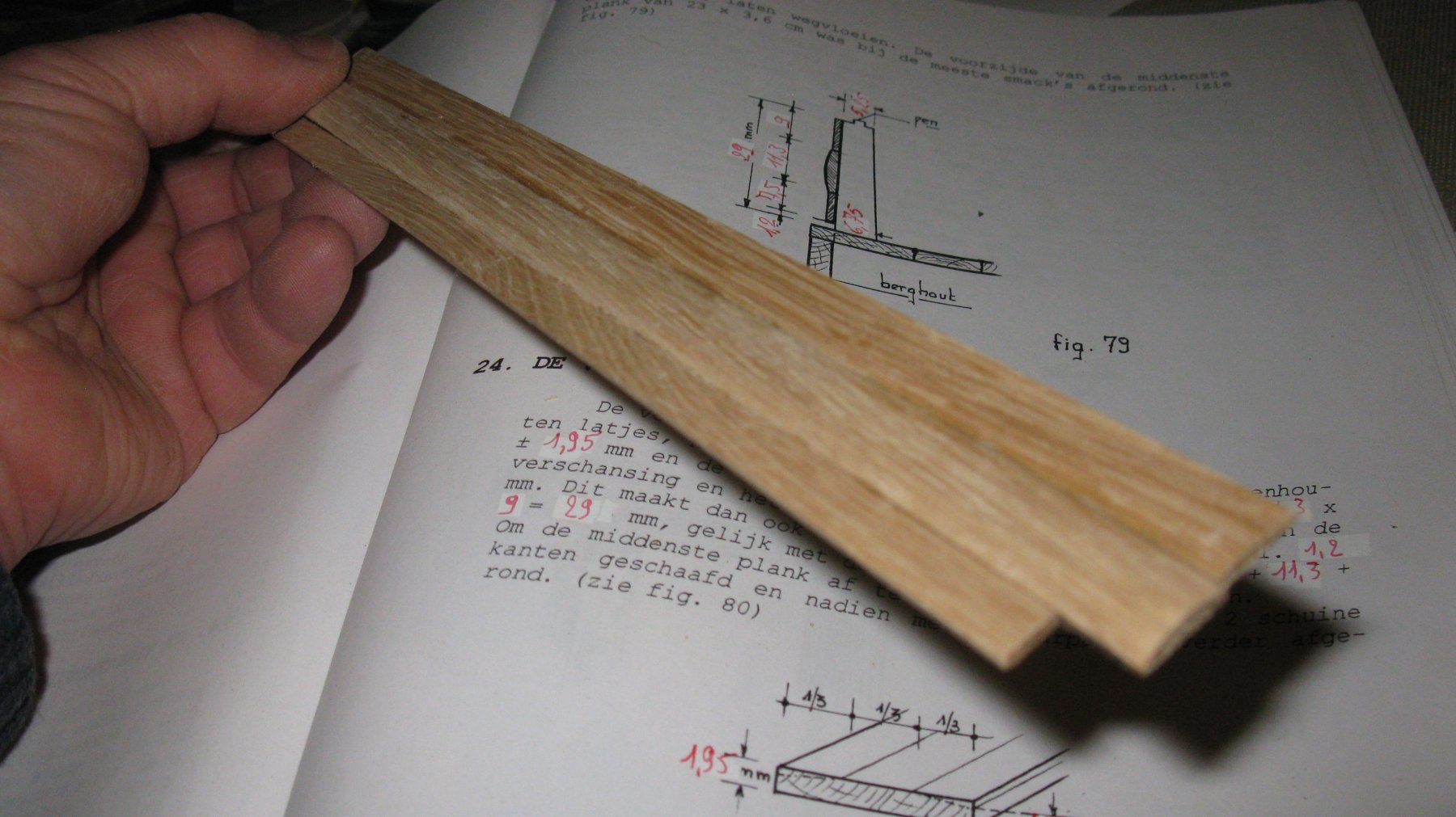
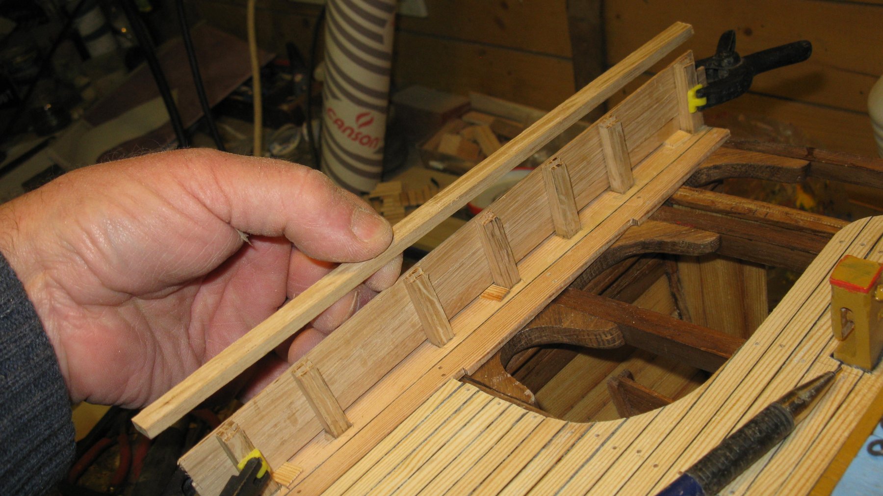
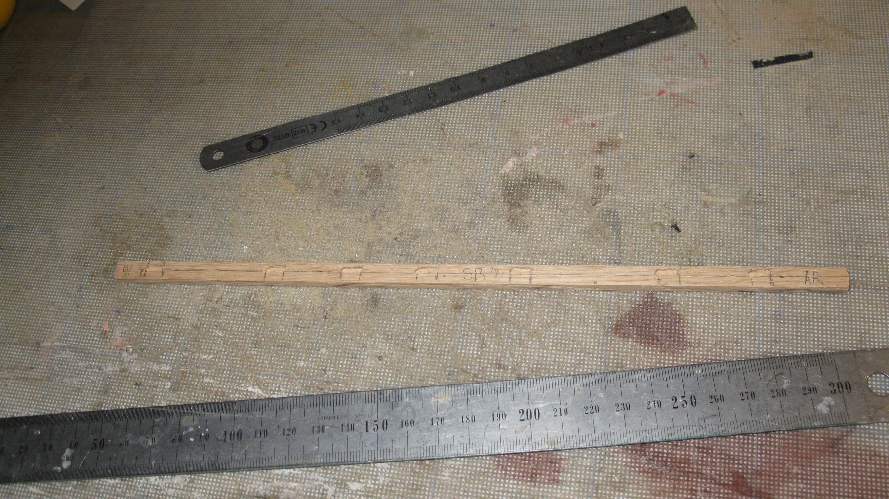
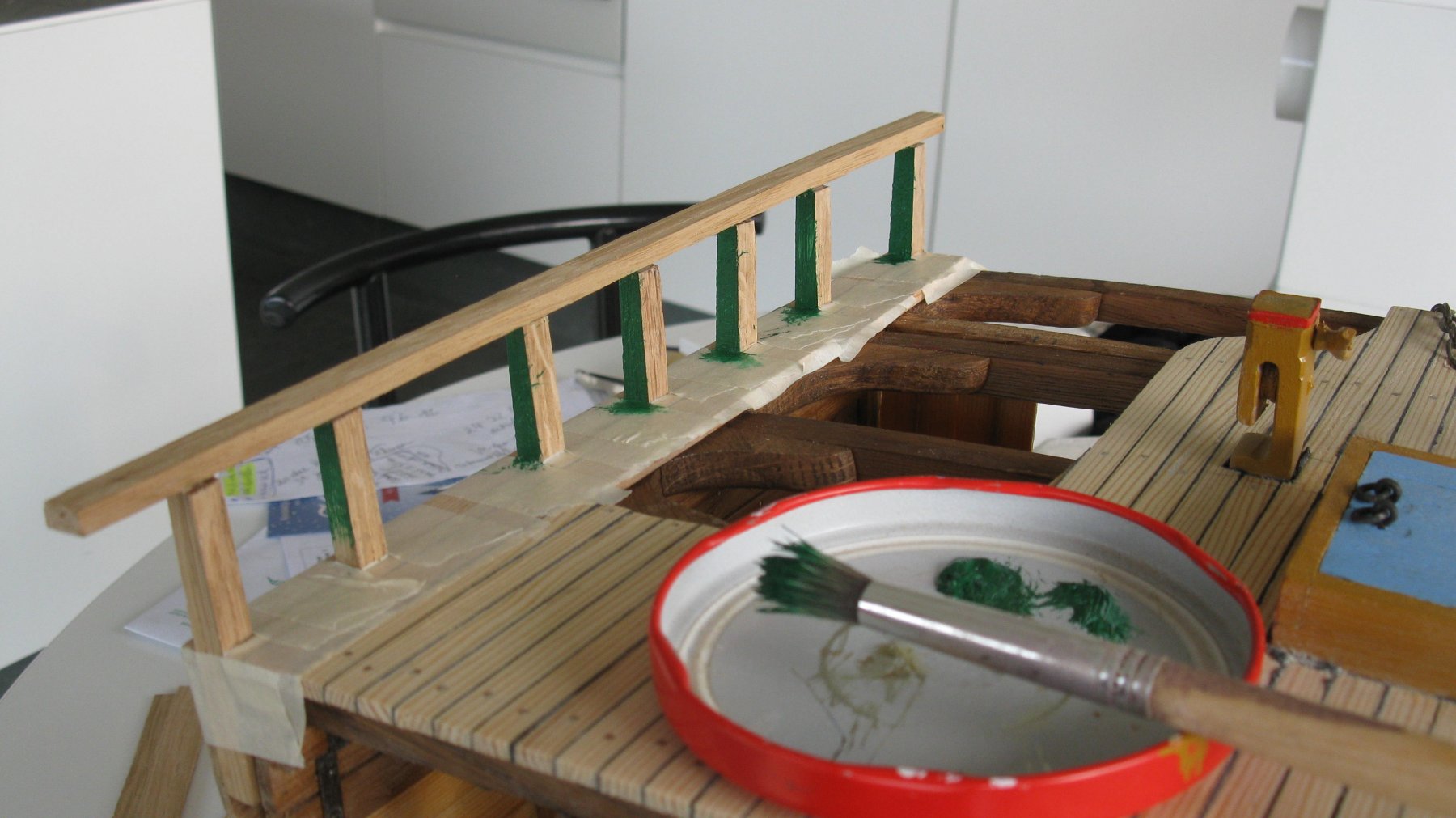
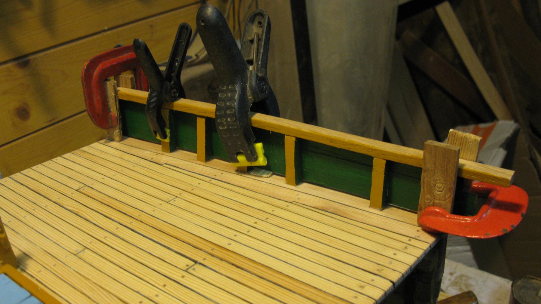
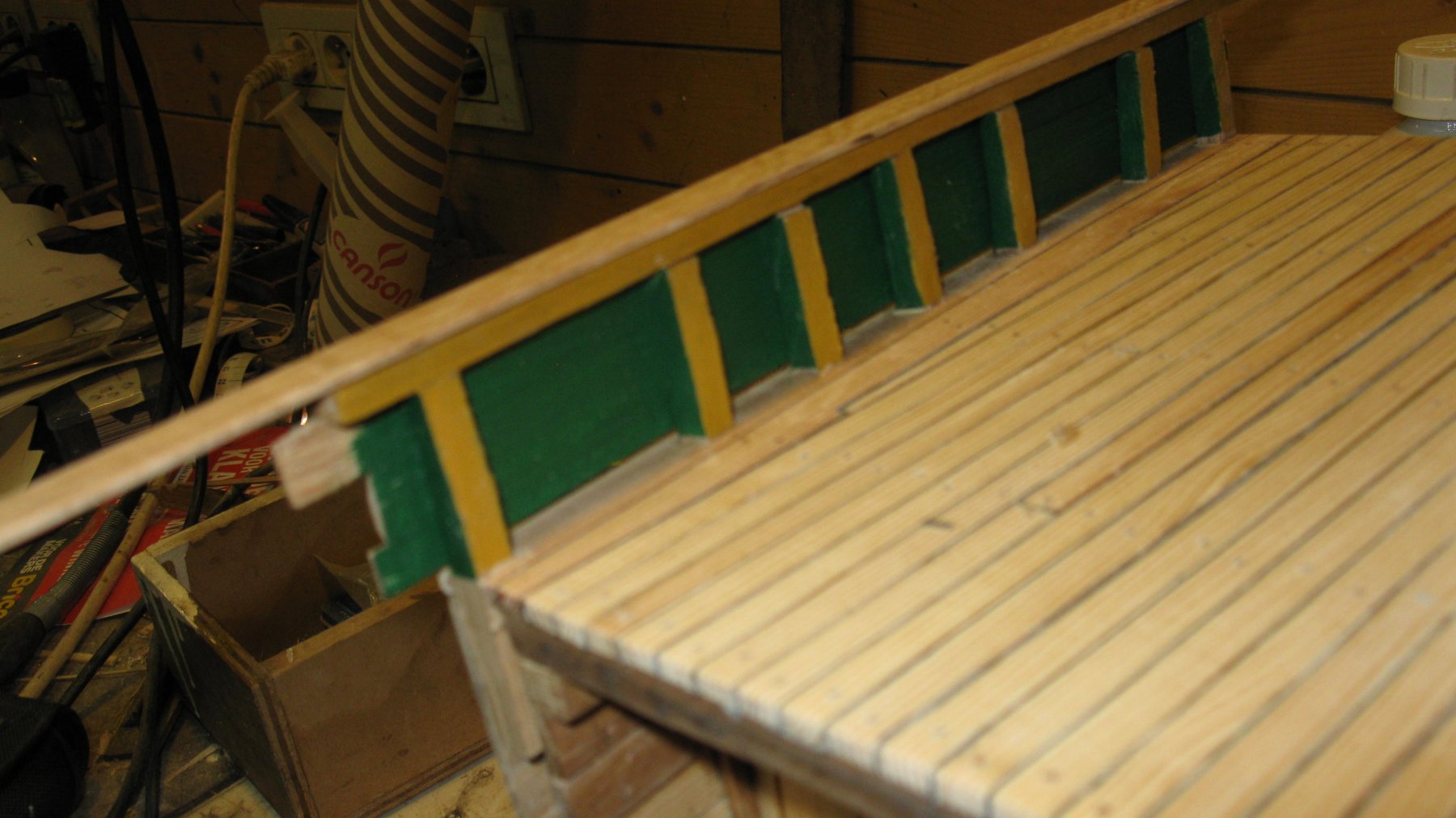
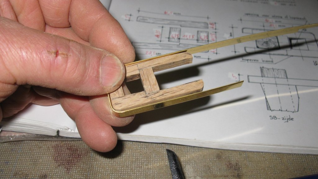
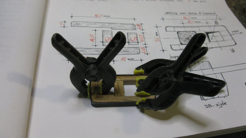
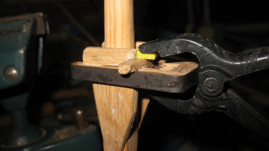
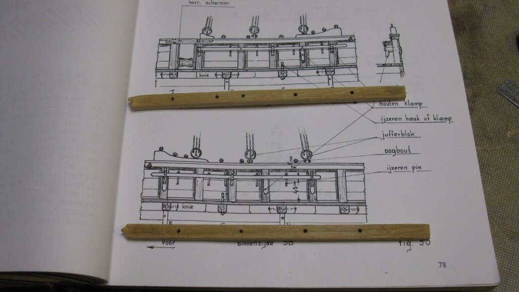
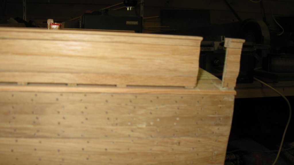
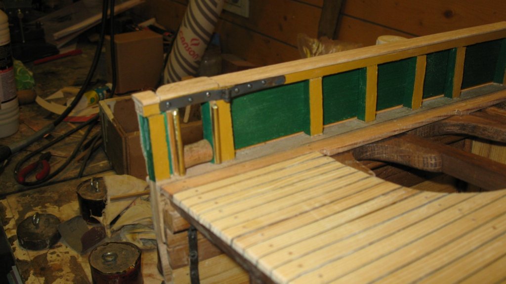
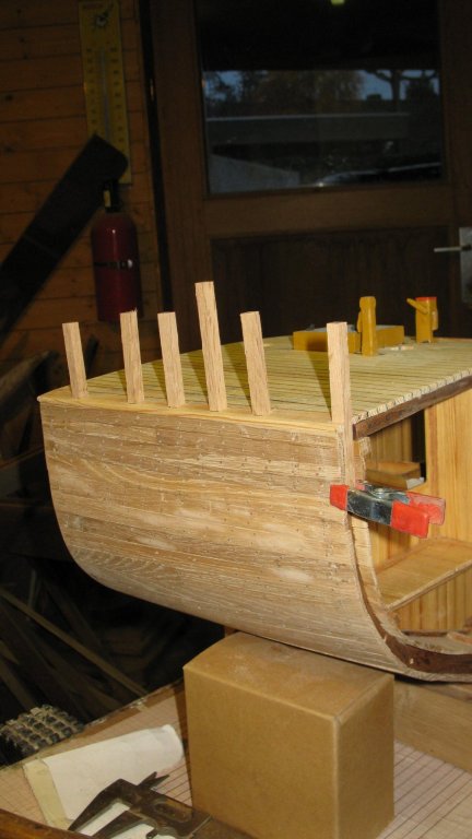
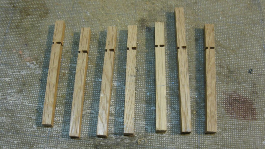
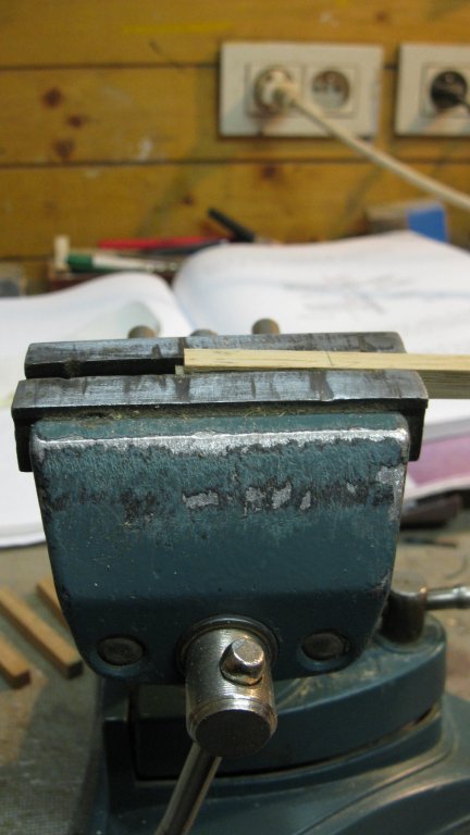
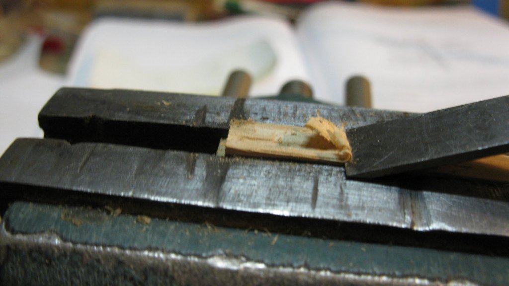
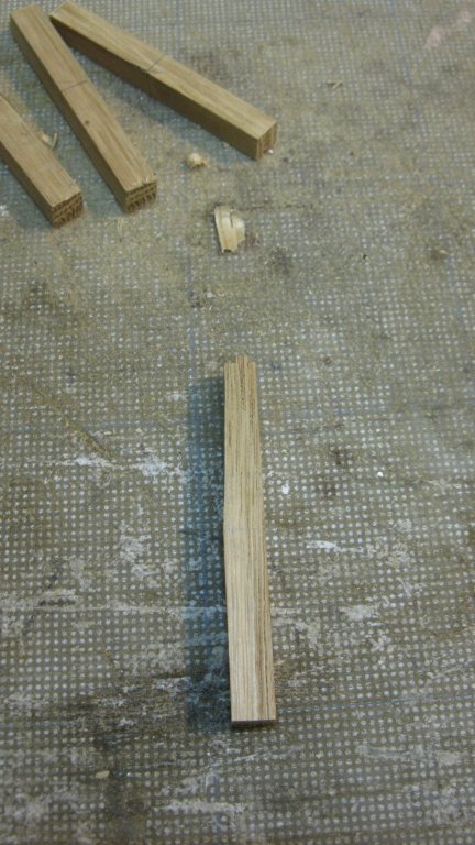
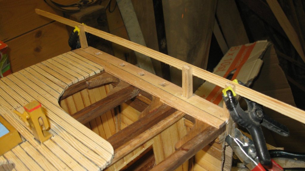
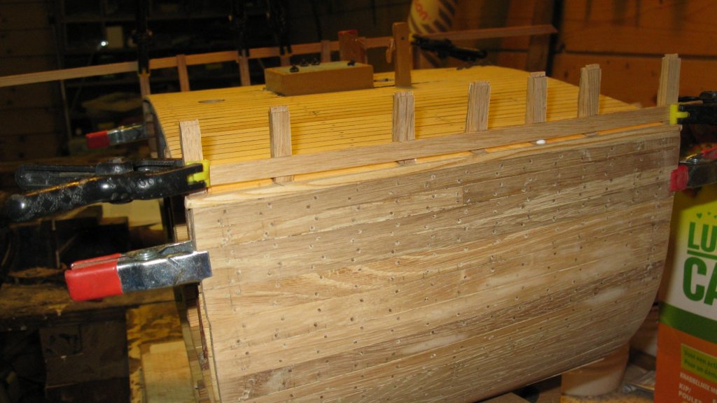
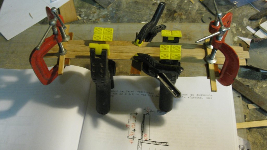
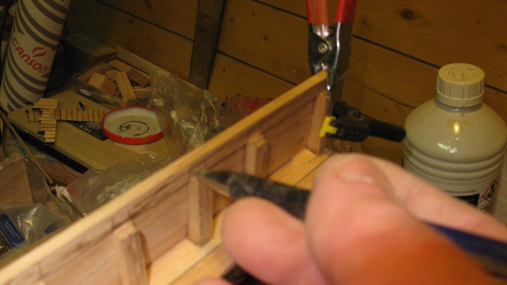
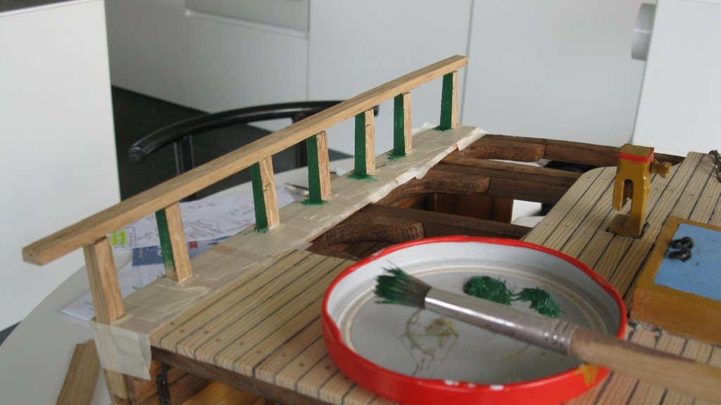
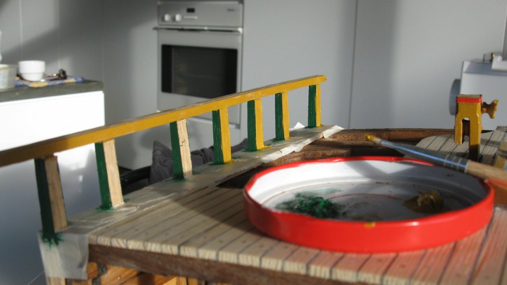
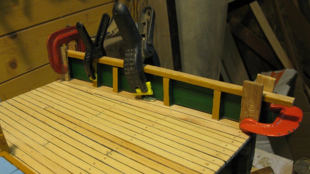
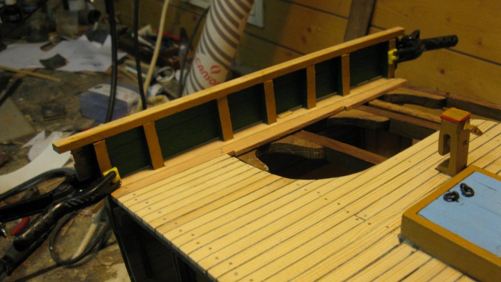
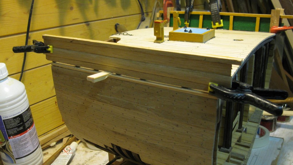
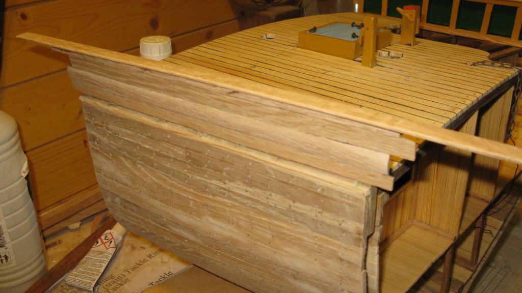
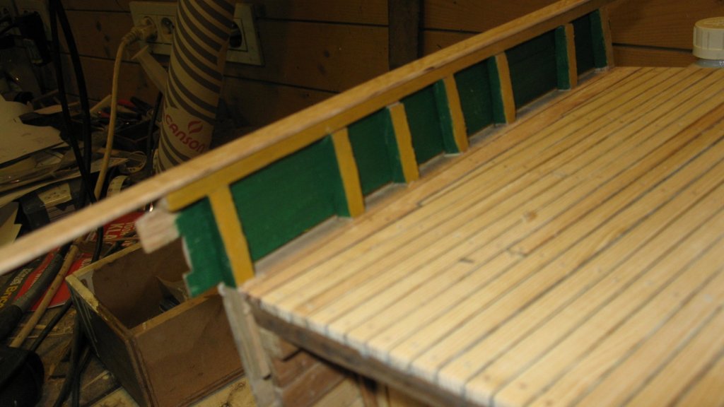
18.6. Deck finishing. The railing. Unusual for Belgian fishing sloops, the stanchions of the railing of this smack are not a part of the frames. Sawing the stanchions. Fitting the stanchions. Lining of the top of the stanchions. With the table circle saw I saw two notches at the top of each stanchion. Then I saw it off to height. Like this I have teeth on top of the stanchions which will fit in grooves in the railing on top of them. The stanchions become narrower towards the top. I shape them with a wood chisel. Gluing the stanchions into place, using a small lath to check the heights. Dry fit of the bottom plank of the railing. The middle plank of the railing has a bulging shape, I sand the shape in it. I want to paint the inside of the railing as a whole, so I first glue the planks together. Fitting them on the model without gluing. On top of the stanchions comes a railing bar. Fitting is marking the stanchion positions. Making notches for the stanchion teeth. I first drilled them an d finished them then with the chisel. Gluing the bars on the stanchions. I use some weights to keep them into position until the glue is dry. Changed my workshop for the kitchen for a while and painting the stanchions and railing bar in ocher and green, which were apparently the common colors on these vessels. Painting also the inside of the railing planks in green. Gluing the railing planks against the stanchions. I am using a wedge in the middle to make the planks fit nicely with the bar. On top of the railing bar comes a cover shelf.


- 219 replies
-
- 11
-
-
- smack
- cross-section
- (and 2 more)
-
Woodeater, You and your friend Sergey are real artists. Did you make the showcase for la Legère yourself?
-
I am looking forward to the making process of that lamp. I never saw this model of combined nav lights before.
-
Mehmet, I find the weathering very realistic. However if it was a real boat I would rather prefer to stay on shore. Do you still plan to put it in a diorama?