


aydingocer
-
Posts
857 -
Joined
-
Last visited
Content Type
Profiles
Forums
Gallery
Events
Posts posted by aydingocer
-
-
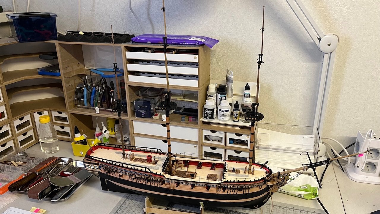
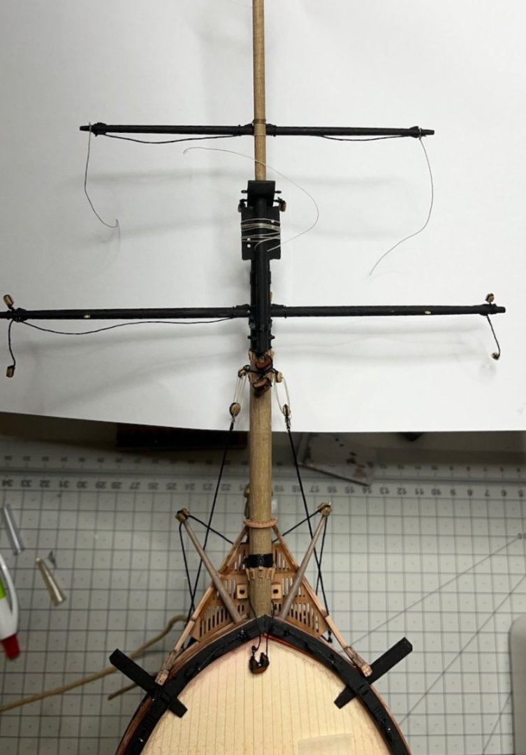
Build day 124: 1 hr / Total 269 hours
Photo 778: Alright. The masts are carefully in place now. Apologies for the noisy background.
- mtaylor, Theodosius, Glenn-UK and 2 others
-
 5
5
-
-
Another question: How deep should I insert each mast through their slots? Or better way to ask; how high should they rise from their decks? I didn't find much clue in the plans.
Using my caliper, I measured the following depts for their slots. Shall I insert them all the way?
Fore Mast: 66 mm
Main Mast: 39 mm
Mizzen mast: 66 mm.
Thanks in advance for the answers.
/Aydin
-
Gathering from the manual and plans, this is roughly the order I am planning to follow.
How does it look? Any advice, warning, suggestions appreciated.
- Fit the masts
- Rig lower shrouds
- Rig upper shrouds
- Fit the yards (not rigging them yet)
- Fit the crossjack sling to the crossjack yard (at this point for accesibility)
- Rig the mast stays
- (Omit Main Stay Tackle and Fore Hatch Tackle at this stage)
- Add the Crowsfeet to the mast tops
- Rig the back stays
- Rig the yards
- Fit Sheets and Tacks
- Fit the Main Stay Tackle (but do not lash done yet)
- Rig the Yard Braces
- Fit the ship's boats
- Lash down the Main Stay Tackle and Fore Hatch Tackle
Regards,
Aydin
-
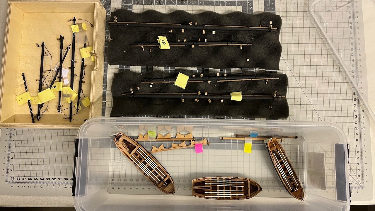
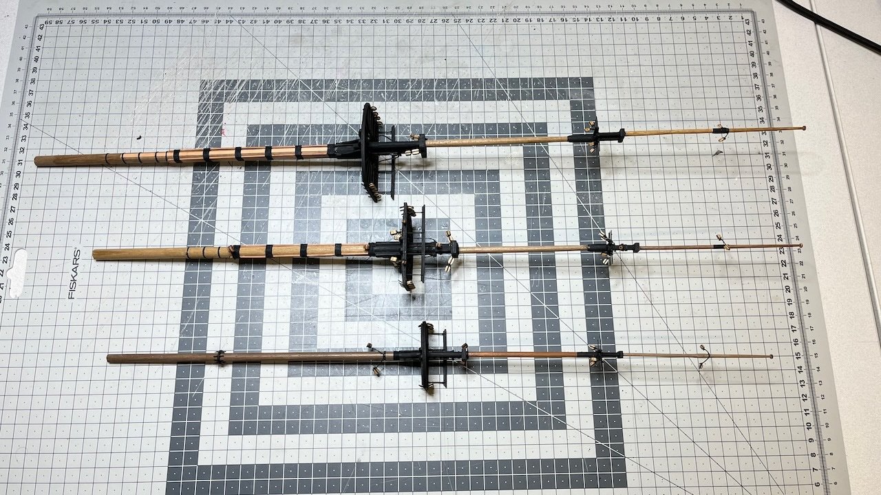
After a short break for some other projects occupying my workbench, my Sphinx is back on the dock. Now all the masts, yards and boats ready, it is time to put them together and start rigging.
Photos 775-777
- DonSangria, Glenn-UK, mtaylor and 1 other
-
4
-
Build day 123: 4,5 hr / Total 268 hours
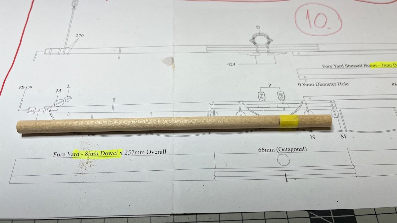
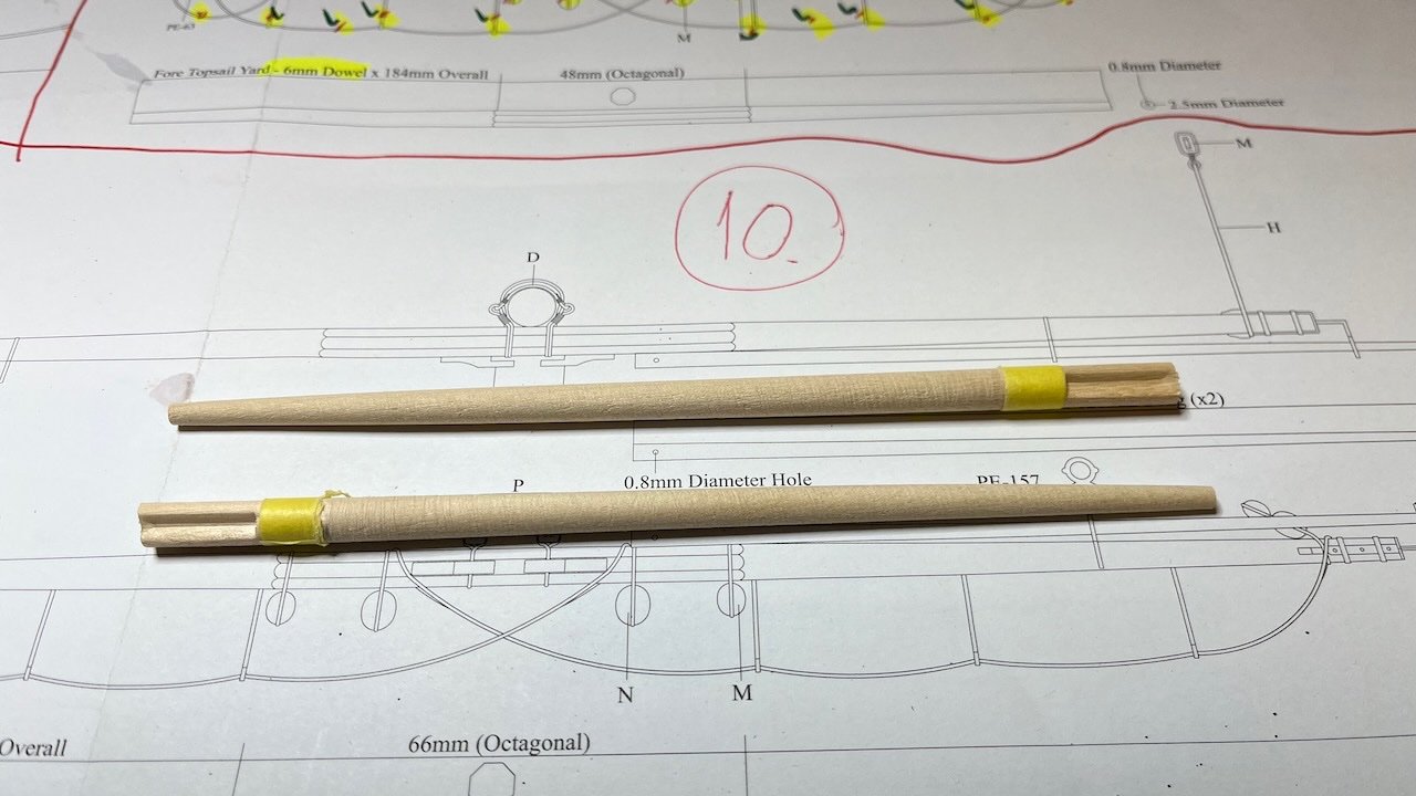
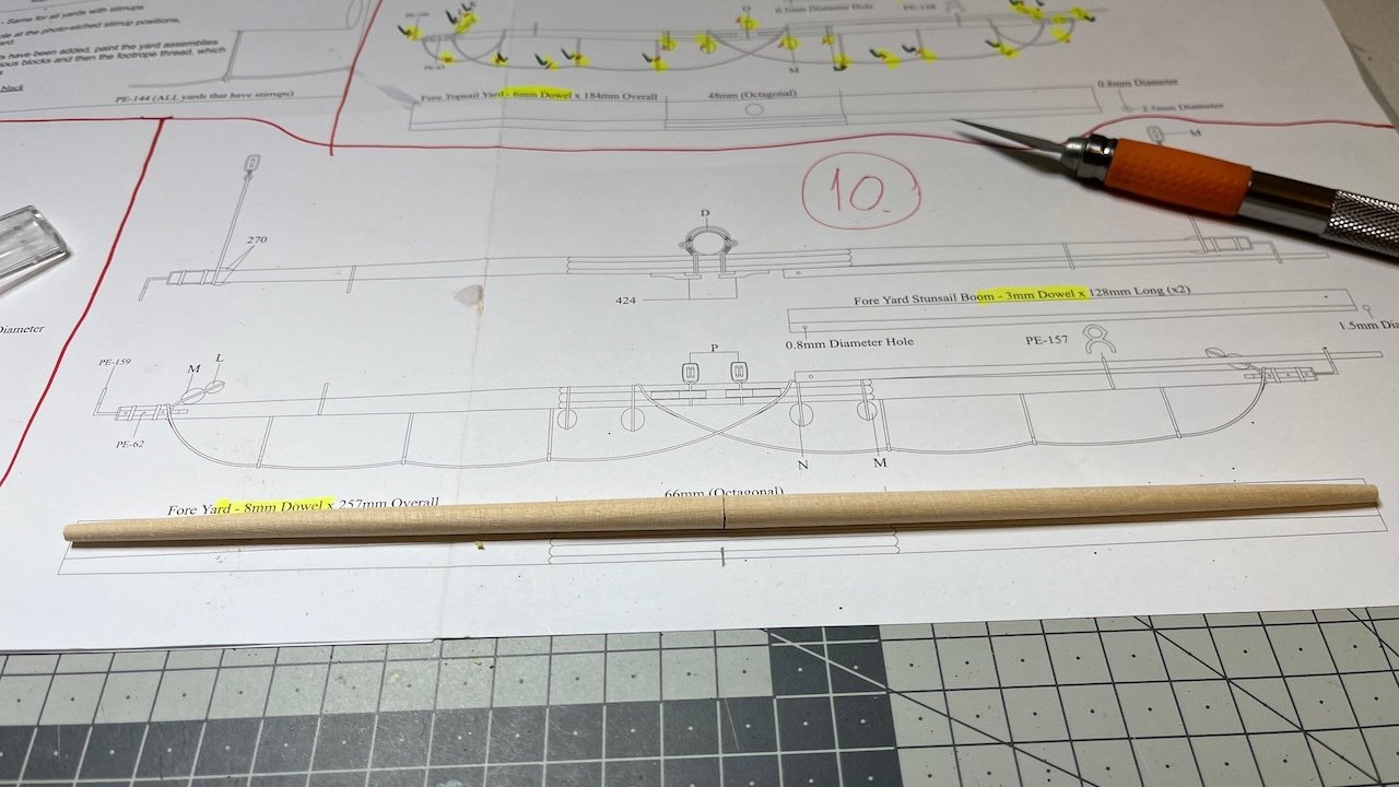
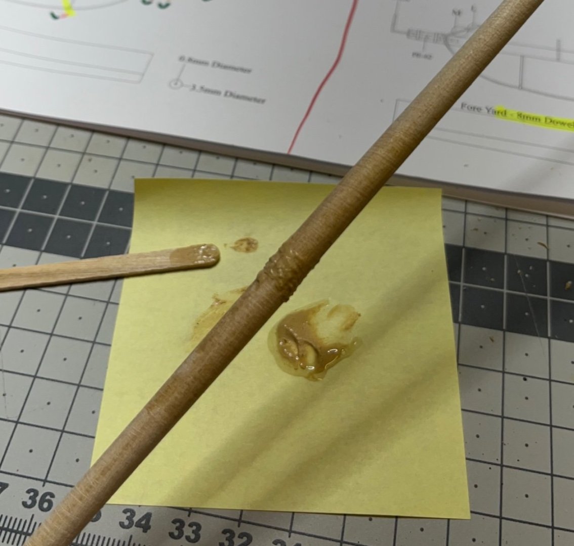
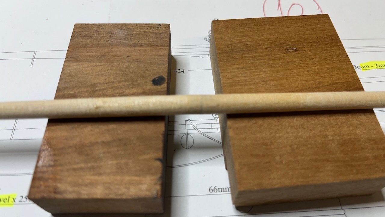
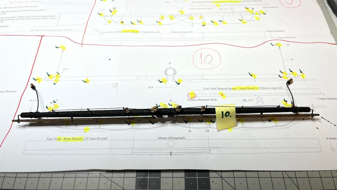
Fore Yard, the last one of my yard construction. For tapering I followed a different approach at this one. I used two halves tapered on one side, the joint glued together using pin enforcement and wood fill. Partly out of curiosity, partly thinking it would be easier to make symmetrical tapers at both ends (you can put side by side and compare). Also the joint would not be visible since I paint the yard to black. Overall it seems to work.
Photos 768-774:
Here as usual the dents on the thicker edges are from the drill chuck:

Complete.
-
Build days 121-122: 2,5 hr / Total 263,5 hours
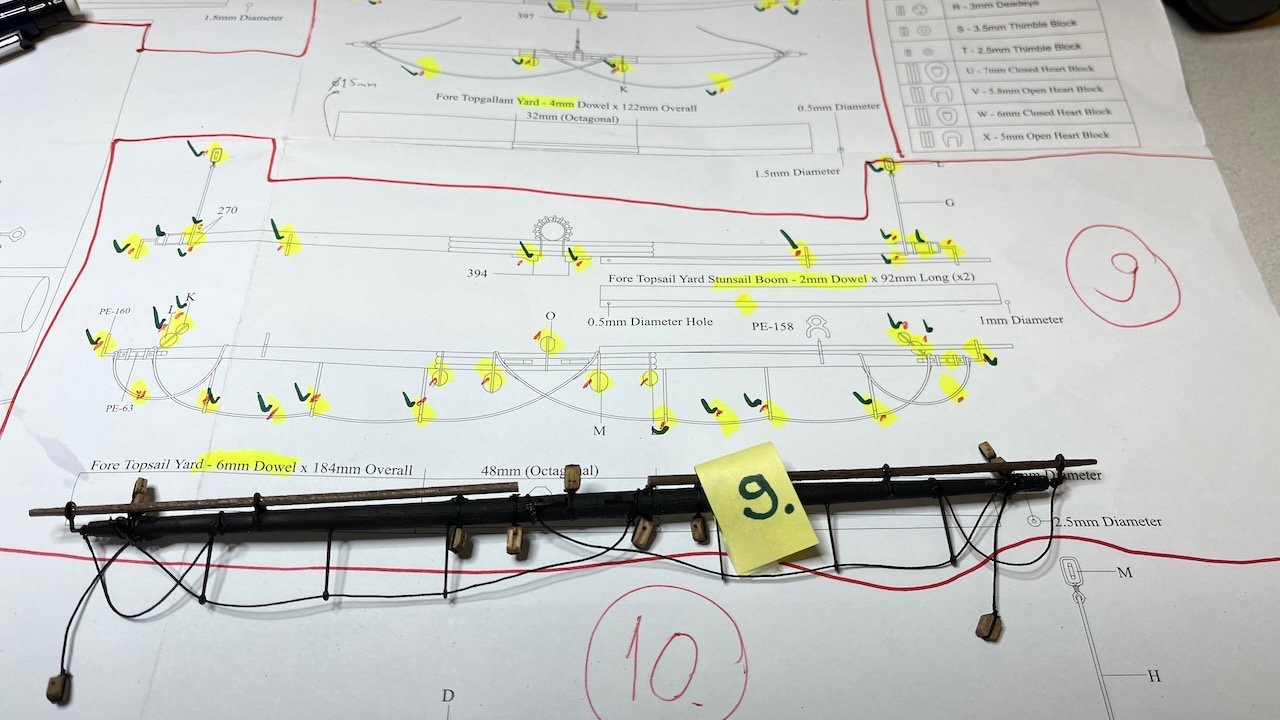
Fore Topsail Yard. Similar process here with nothing too special to mention.
Photo 767:
- mtaylor, mugje, chris watton and 2 others
-
5
-
Build day 120: 5 hr / Total 261 hours
Crossjack Yard, Fore Topgallant Yard and Main Topsail Yards ready. Below Fore Topgallant- and Main Topsail Yards.
Photos 765-766:
- Glenn-UK, chris watton and mtaylor
-
3
-
1 hour ago, allanyed said:
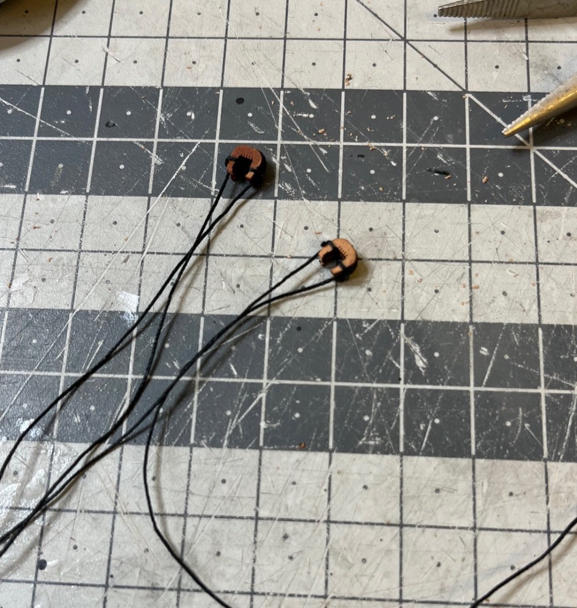
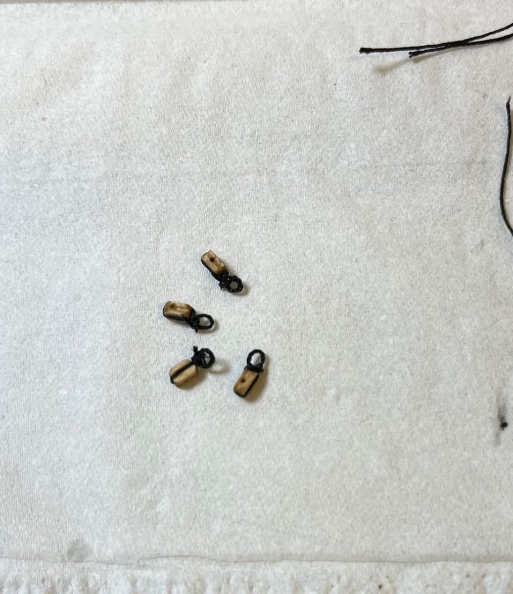
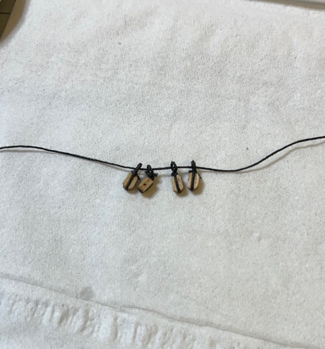
Very neat work Aydingocer. One thing that looks off and it may be the photo but the blocks in the last photo appear to be upside down so the line would rub against the inside of the shell rather than around the sheave. If they are upside down it would be pretty easy to drill the second hole as in the second photo below and would look as found on real blocks anyway.
Allan
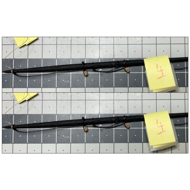
Good point, Allan. Actually until now I never paid attention to the orientation of the holes. I even found it is easier to rig if the hole is actually further away from the mast or yard, making it easier to reach during rigging. Hmm. I am not sure if I modify those I have already done but definitely will check their position going forward. 👍
/Aydin
-
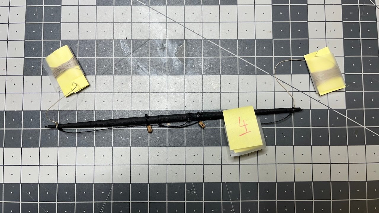
Build day 119 continued: 1 hr / Total 256 hours
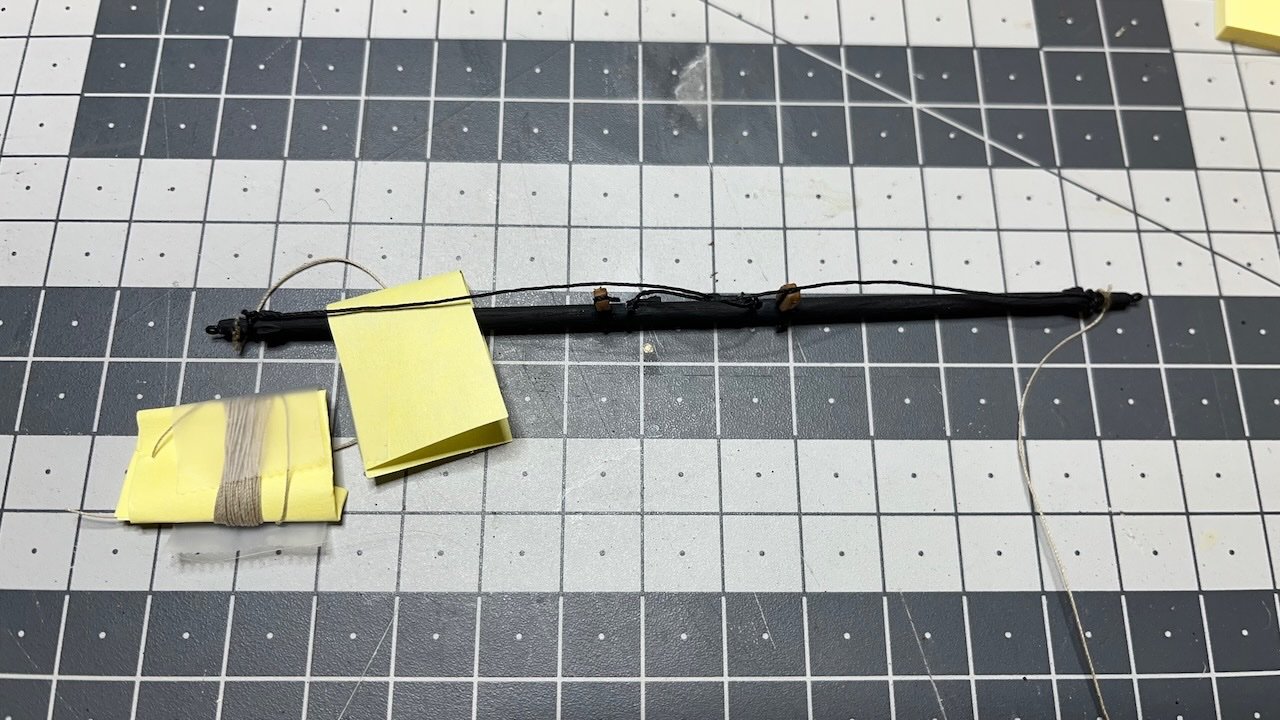
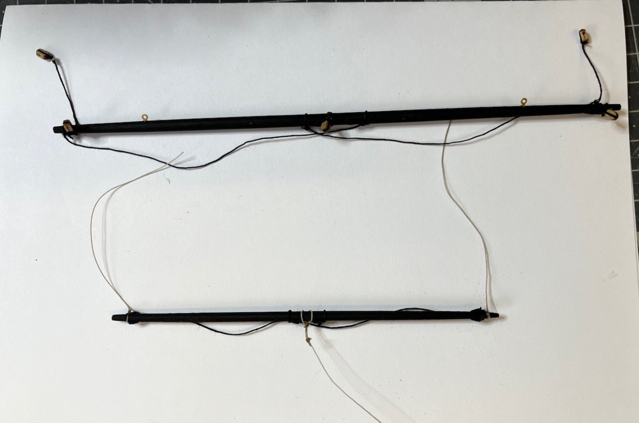
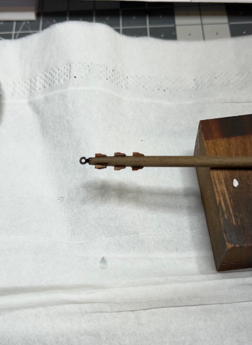
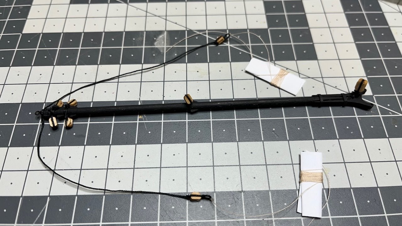
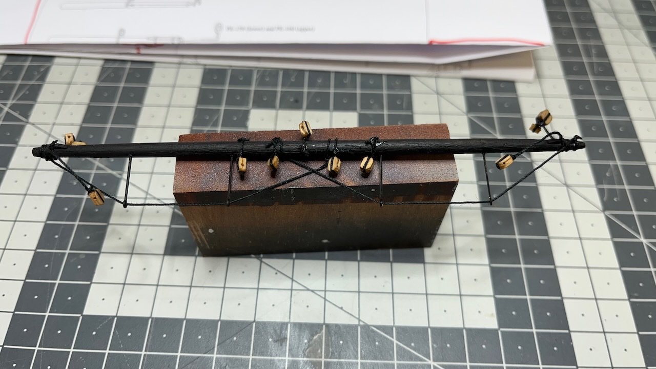
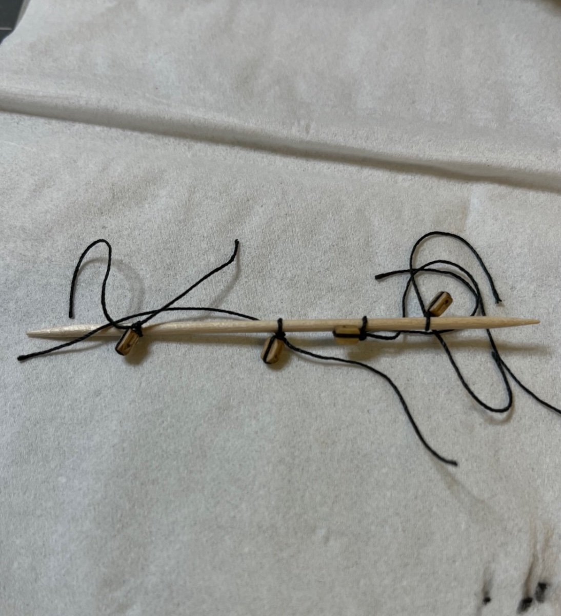
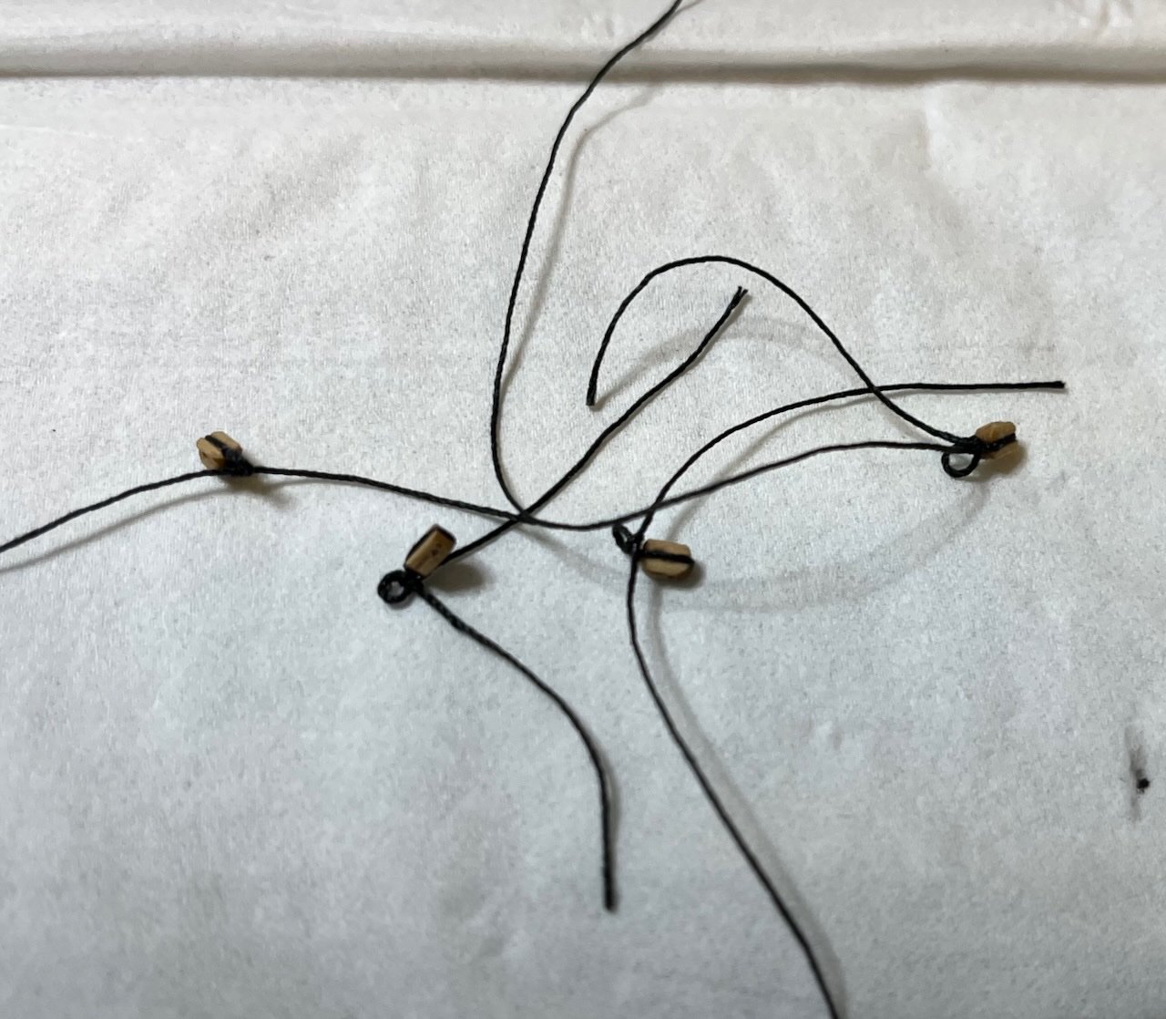
Photo 764: Main Topgallant Yard complete. 70cm long natural thread is attached on both ends. I wrapped them around a piece of paper and secured with a tape in order to keep them safe moving around.
- Clark, Glenn-UK, chris watton and 2 others
-
5
-
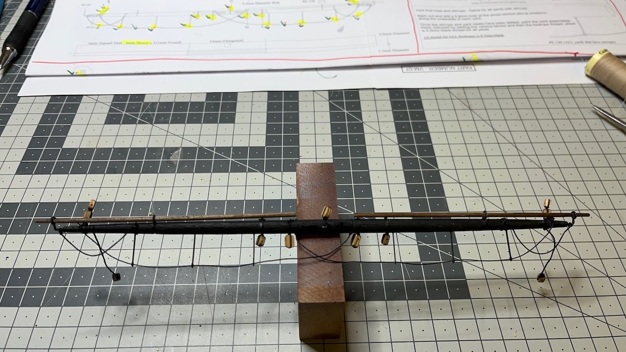
Build day 119: 2 hr / Total 255 hours
Photo 763: Main Yard complete. It took altogether about 3 hours.
- Knocklouder, mtaylor, Glenn-UK and 1 other
-
4
-
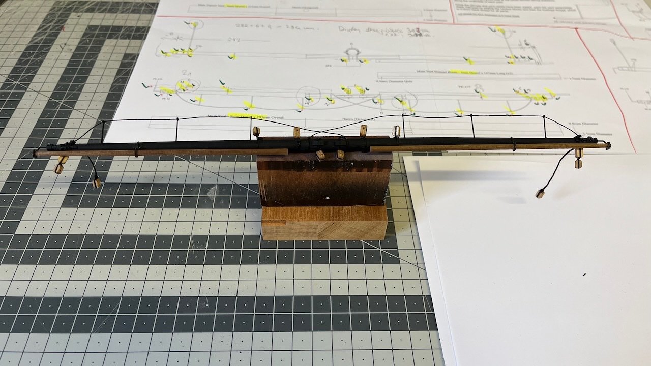
Build day 118: 1 hr / Total 253 hours
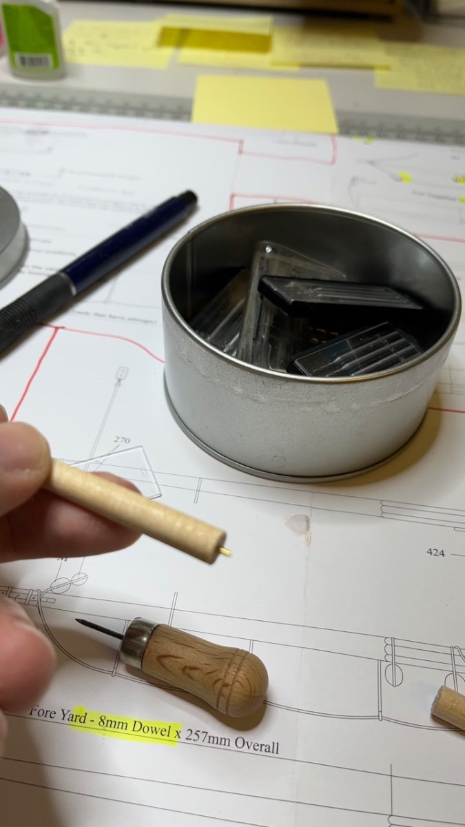
Main yard. It normally uses 8 mm dowel to be tapered to 6mm in the middle and 3.5mm at the ends. I found a 6 mm dowel in my stock that saved me from most of the heavy work. It will be painted in black therefore the color does not matter
I have to regretfully confess that the total length of my Main Yard will be 6 mm shorter than in the plan from both ends. The reason is that my display shelf is just damn 10 mm too narrow to fit the Sphinx. The Main Yard determines the width of the ship.
Photo 762: Dowel tapered. All the metal and wooden fittings (except for the blocks) are in the metal cup.
- Ryland Craze, Glenn-UK, CiscoH and 4 others
-
7
-
-
-
-
Build days 111-114: 7,5 hrs / Total 247,5 hours
Summer travels, spending time outside followed by a thorough workdesk rearrangement slowed down the build log a bit. But nevertheless there is some progress to share.
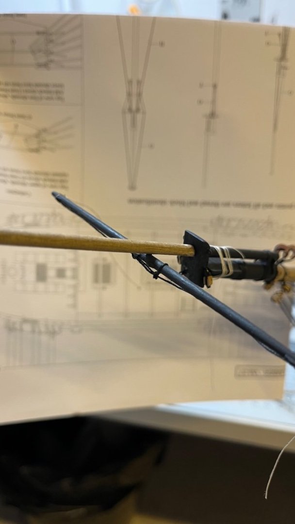
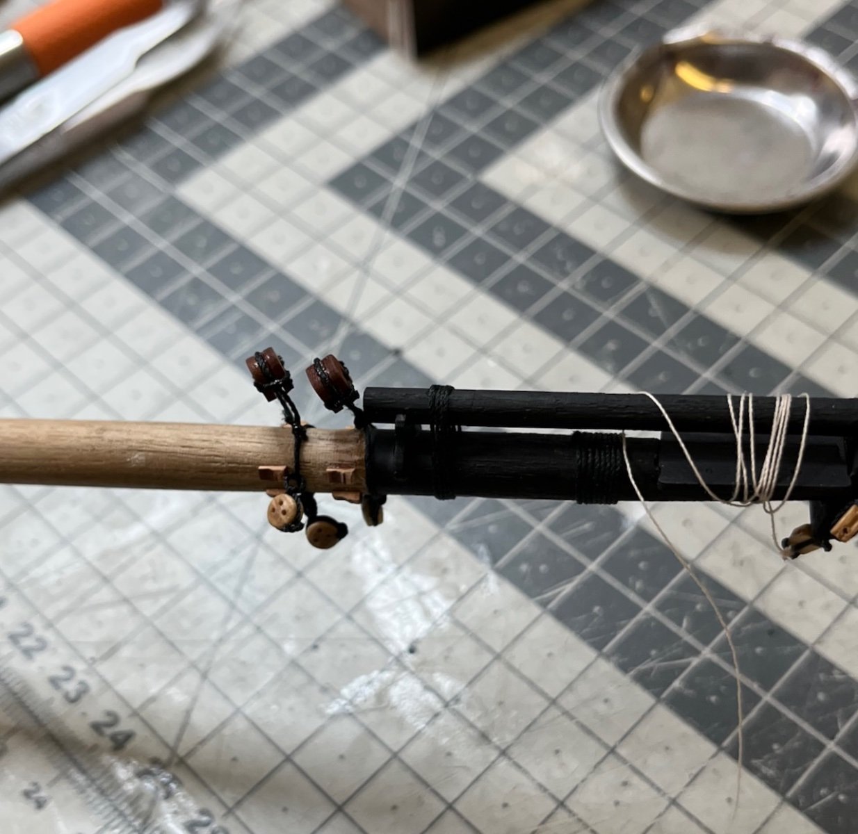
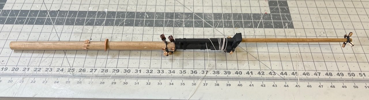
Photos 753-755: Spritsail yards construction and installation on the Bowsprit. These are the first two of the many yards that will come. I used nails (clipped their heads and inserted to 0.5mm holes I drilled on both parts) to mount the yards to the Bowsprit, strengthened by the threads.
-
13 hours ago, allanyed said:
Hi Aydingocer
This is great as you show a very clever way to do this with a simple tool such as your drill.
Do the yards on a sixth rate have an octagon center quarter? The octagon shape in the center quarter of the yards started about 1690 according The Masting and Rigging of English Ships of War, page 13 but Lees does not say if all yards on all rates had this design feature after 1690 so I am curious. Volume IV of TFFM by David Antscherl describes the octagon on the yards of a 14 gun sloop. If they do take this shape, it is probably easier to make the octagon at the maximum dimension needed, then sand as you have clearly shown leaving the center quarter as an octagon.
Allan
Hi Allan,
Thanks for the appraisal.
I applied a slight octagon shape on this one yes, mostly to try and see if it is worth the effort. This is the spritsail yard. The octagon is barely noticeable and it will be even less visible once I have mounted it on the bowsprit and among the riggings. So I'll decide one by one as I go along. As James also mentioned above they are in the plans and one can skip them at will. Otherwise I am not too knowledgeable about the period accuracy of these ships.
/Aydin
-
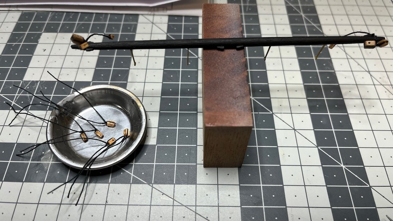
Yards' construction.
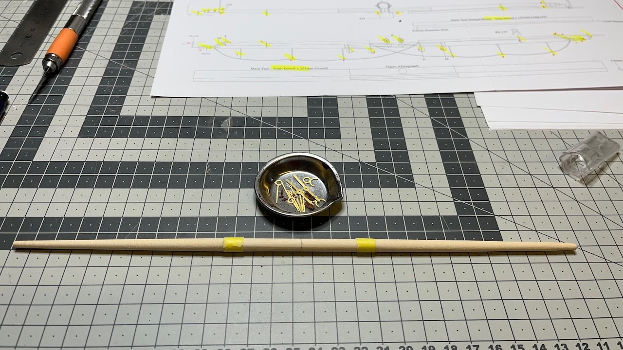
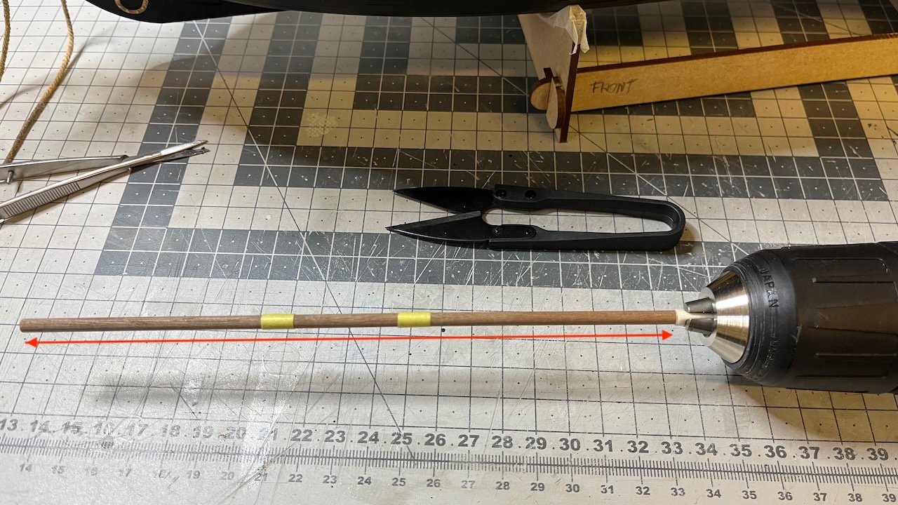
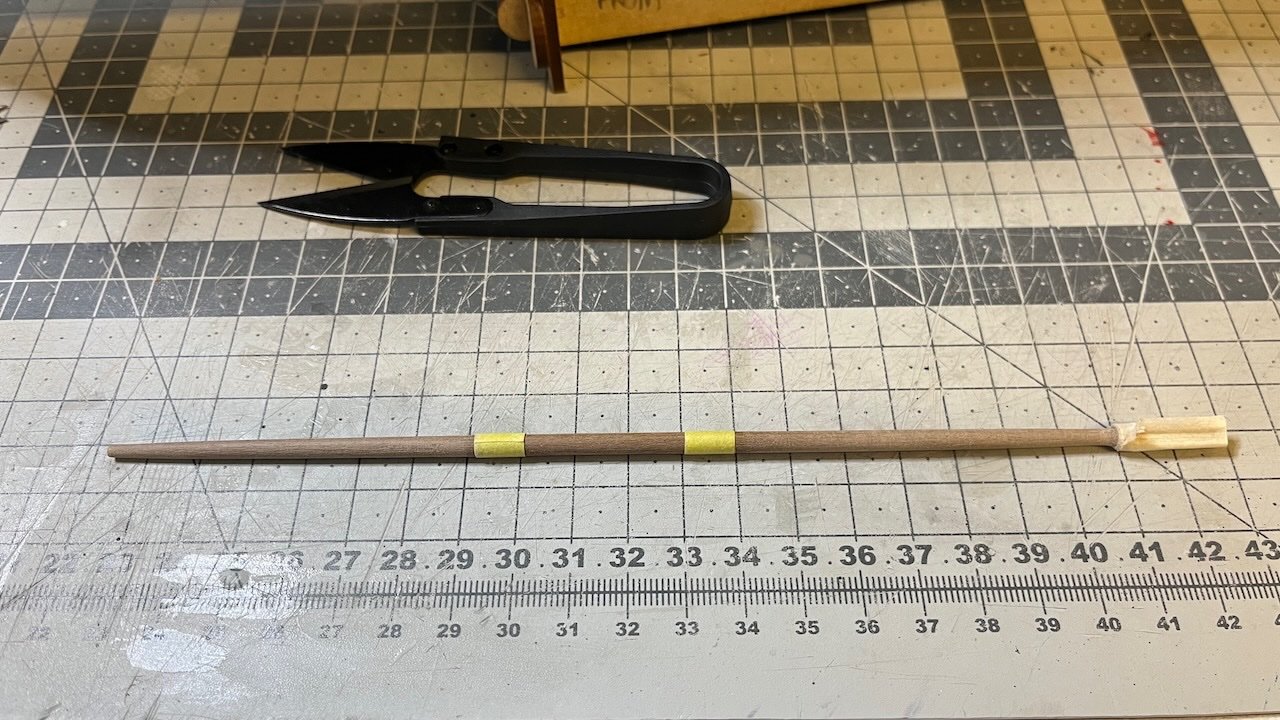
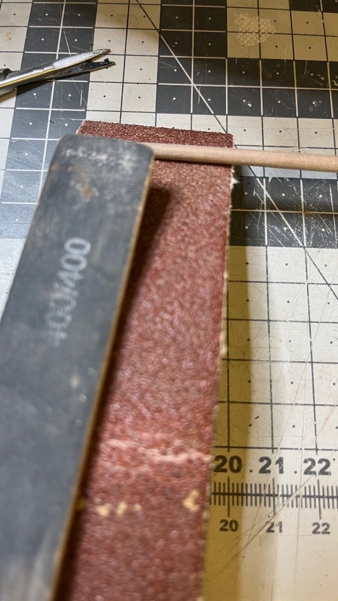
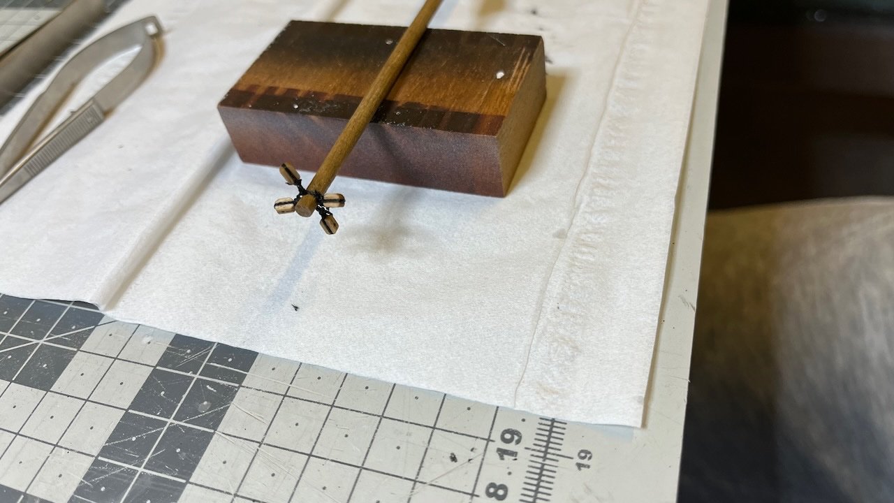
Photos 747-752: As the yards need tapering from both ends, here is how I do it.
I cut the dowel around 2cm longer than the yard. The excess amount is for inserting into the screwdriver. The red arrow shows the full yard length. Yellow tapes mark the sections (exclusive) that will be tapered.
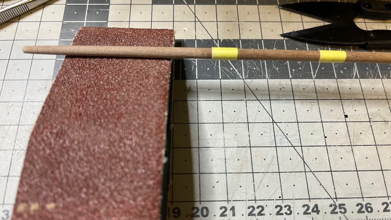
Then I turn on the drilling machine and use the rough sandpaper on a sand block, starting from the far end of the dowel. It helps to press slightly on the dowel with a finger to put the necessary pressure, without burning your finger with the heat from the friction.
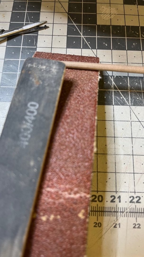
Once I have achieved the final shape, I use a 400 grit sanding stick for smoothening the surface.
Next the other end (i.e. close to the drilling machine). Handling this part after the far end reduces the risk of breaking the dowel, as otherwise it could get too thin to stand the vibration while tapering the other end.
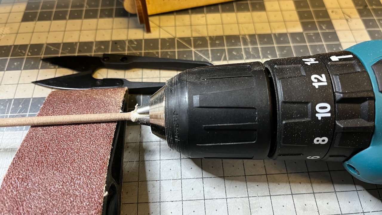
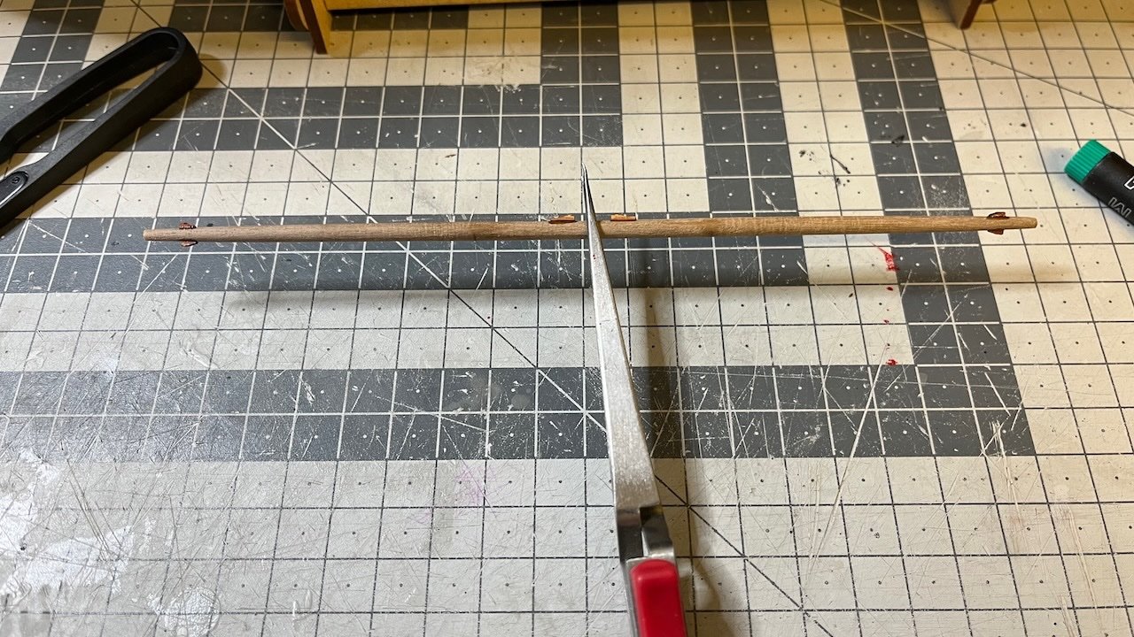
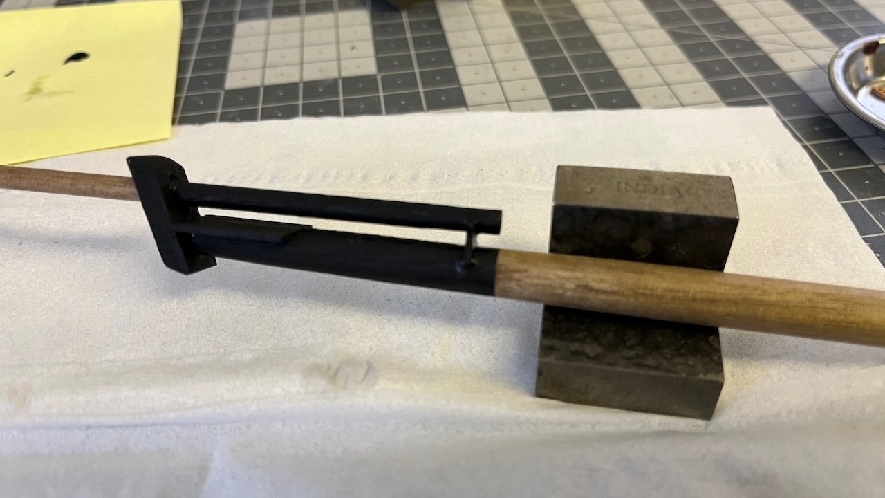
Tapering done. It is time to chop off the drilling machine insert.
Ready
- Knocklouder, Bowline, chris watton and 8 others
-
11
-
13 hours ago, chris watton said:
As they are very close to the shrouds, it may be better to leave them off altogether.
Looking at the photos from Blue Ensign's build log, indeed they would obstruct the shrouds. Hence I'll skip them. Looked fine on his model since he skipped rigging.
- mtaylor and chris watton
-
2
-
Question: In step 689 of the manual, just before construction of the boats, we are advised to leave the Quarterdeck Hammock Cranes for now, as this could impede the fitting of the shrouds. When is the good time to install them? I can't see them in the final completed model photos either.
Thanks in advance.
-
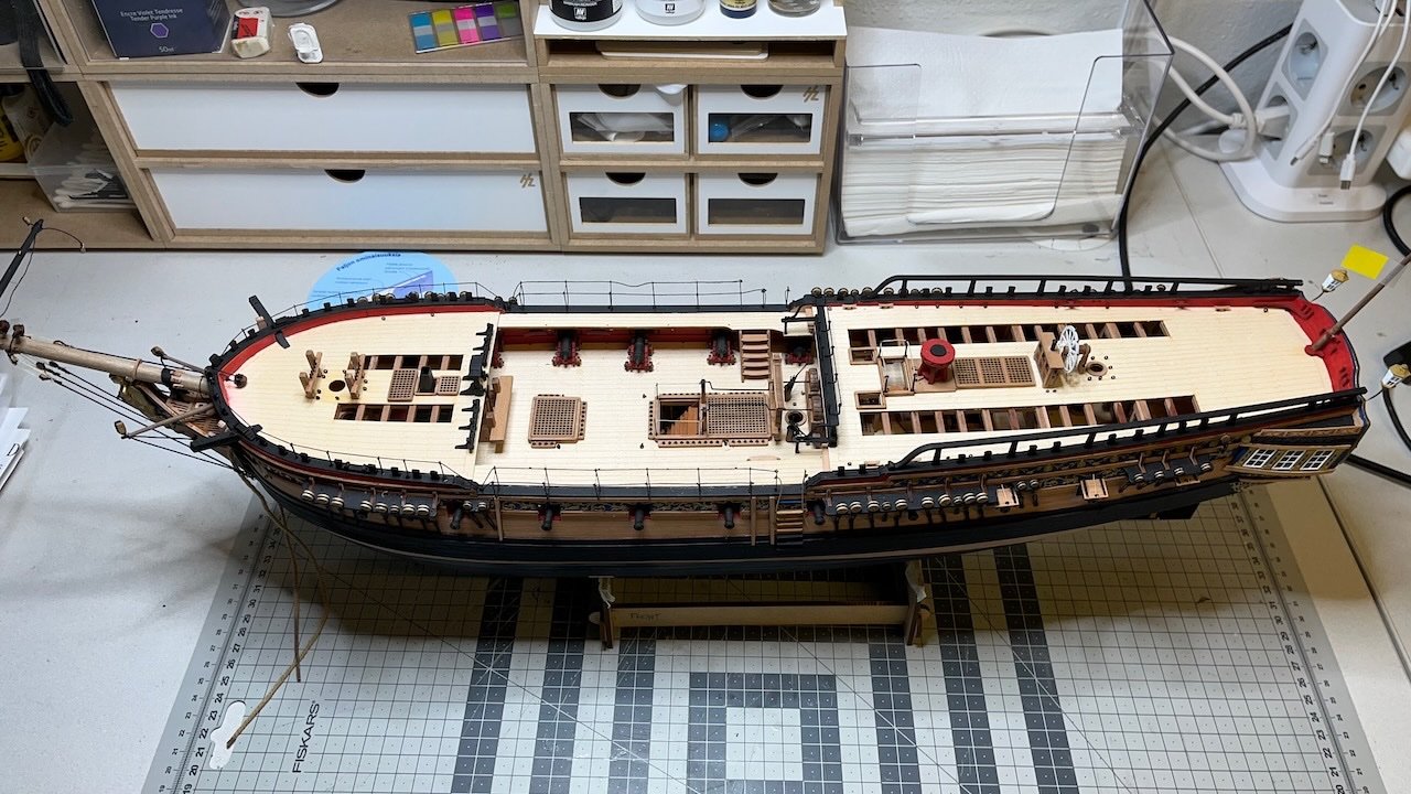
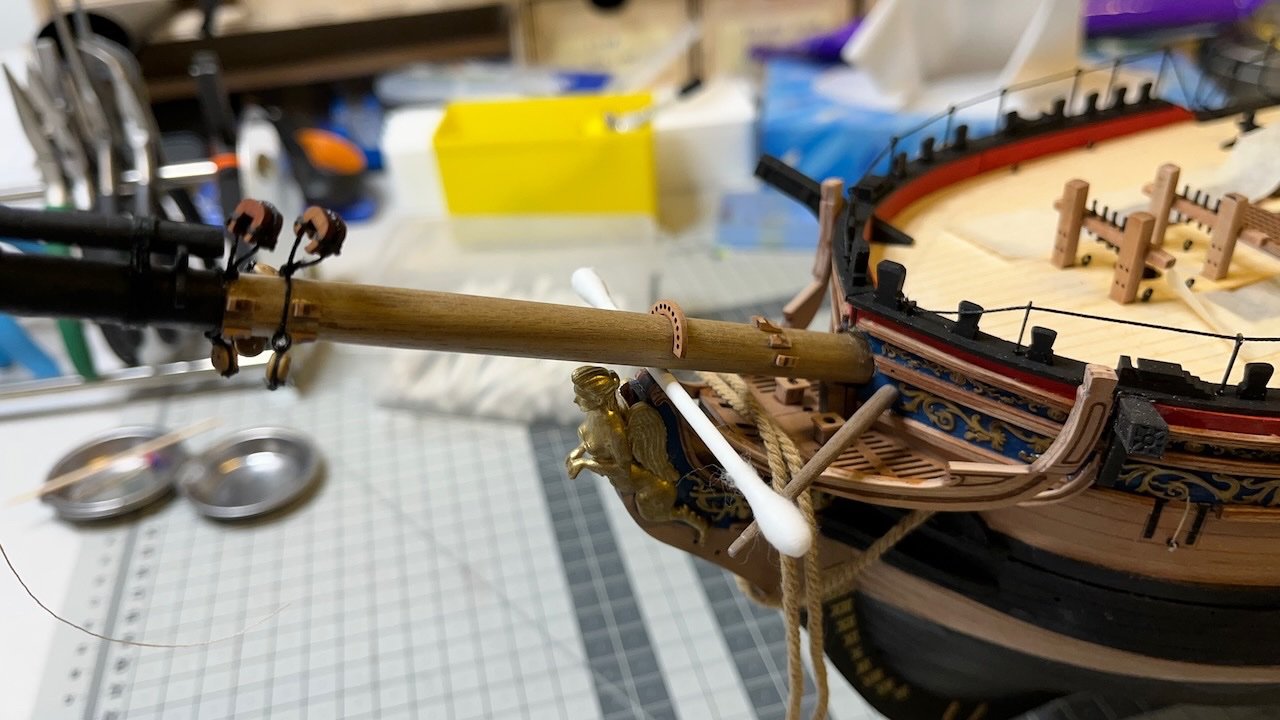
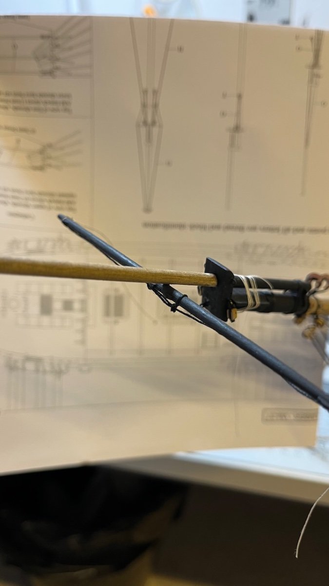
Photo 746: Short update after retuning from a one week trip. The hull is back on the table after the masts and the bowsprit constructions. Glued the bowsprit carefully into place. I dry fit first to make sure (following with the plans) to insert the bowsprit correct amount. It was a relief that when the bottom of the bowsprit finally touched the stopper inside the hull, it was exactly the right length. Here a cotton swab stick is holding the bowsprit in correct height until the glue has dried, preventing it otherwise from resting on top of the lady's head.
Next I will continue with bowsprit gammoning and rigging the bowsprit shrouds and stays once I have gathered my courage 😅.
-
-
-


HMS Sphinx 1775 by aydingocer - Vanguard Models - 1:64 - Revision #2
in - Kit build logs for subjects built from 1751 - 1800
Posted
Just following the instructions. It is supposed to be white")