


aydingocer
-
Posts
858 -
Joined
-
Last visited
Content Type
Profiles
Forums
Gallery
Events
Posts posted by aydingocer
-
-
-
13 minutes ago, DonSangria said:
Maybe you can slide the topmast through the hole from below?
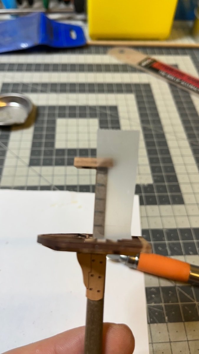
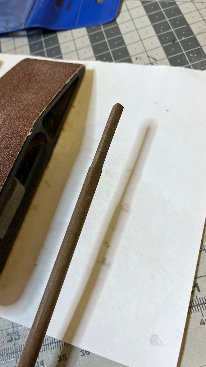
The platform below blocks it to some extent, you'd still need to sand the mast. Also towards the top of the mast there is a thickness of 4.5mm which is thicker than the hole (4mm). Therefore I guess right now the best move is to sand the lower part of the mast until it slides through the cap hole.
-
8 minutes ago, chris watton said:
Ah, OK. I have always put the mast caps on from the tops and slid down into position. If I didn't do that, then I would square the lower part of the mast enough so it could be fitted through the mast cap hole.
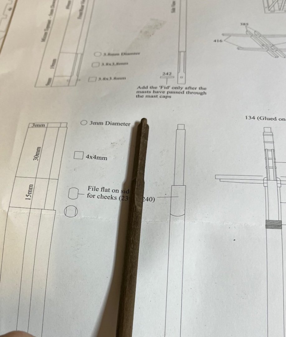
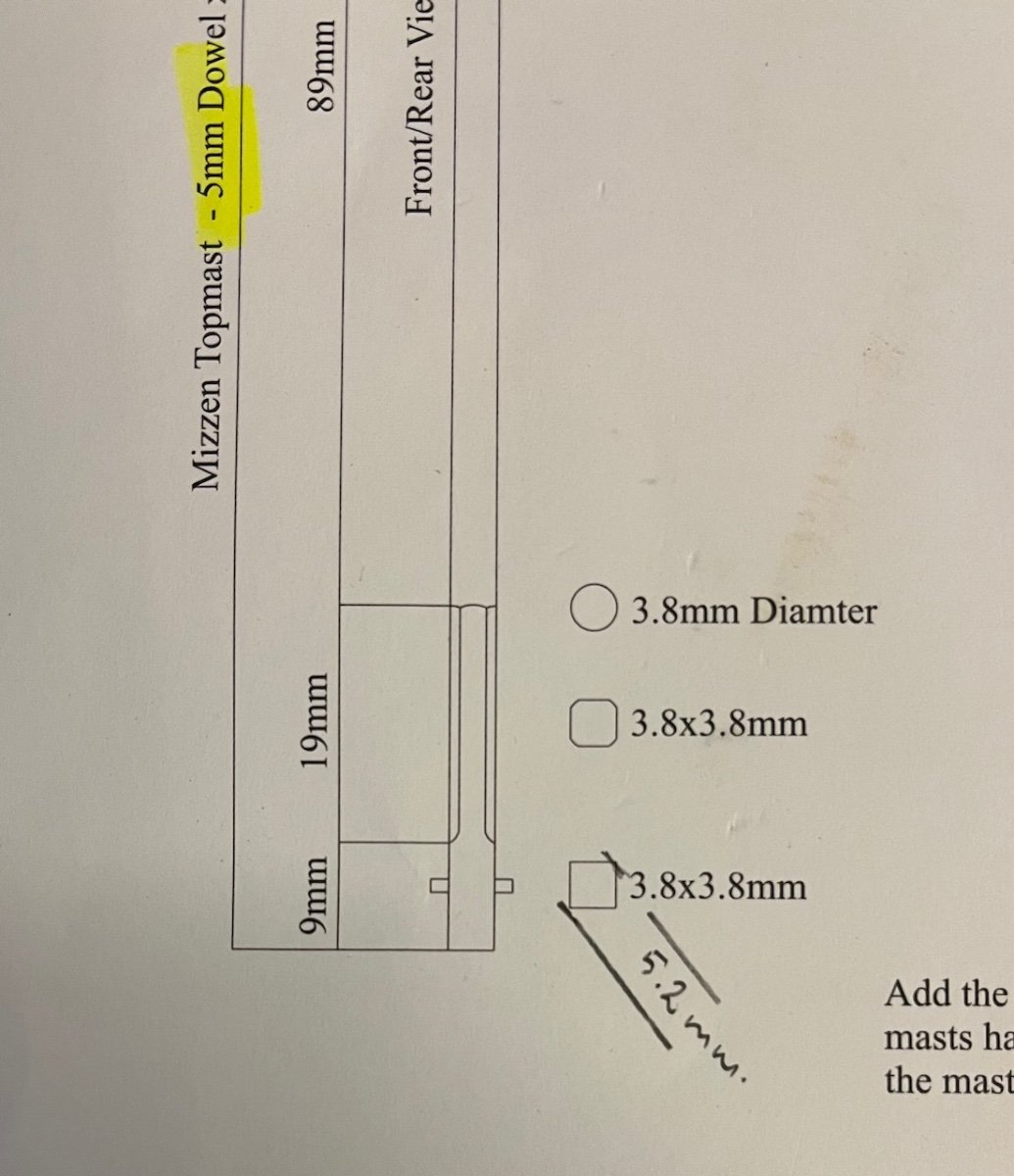
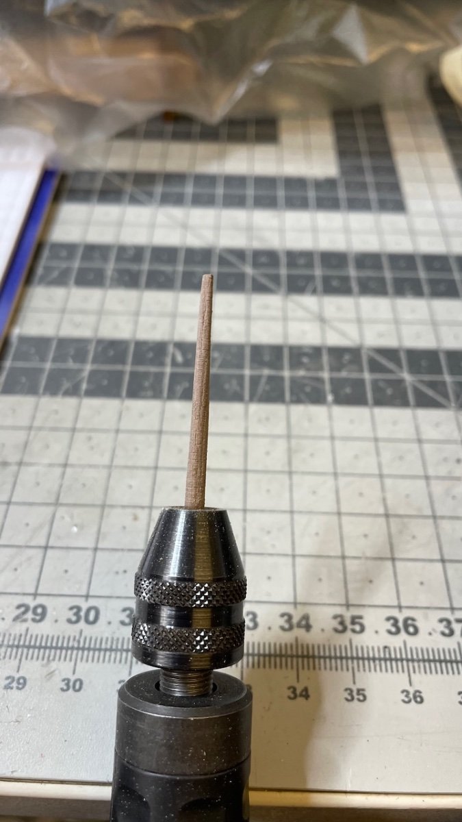
Thanks for the advice. I think in this case I will sand the lower part to thinner than 3.8x3.8 mm, maybe 3.2 x3.2 or something and slightly enlarge the mast cap hole also if I need to.
-
17 minutes ago, chris watton said:
You can push the topmast through the hole in the mast cap and then add the fid.
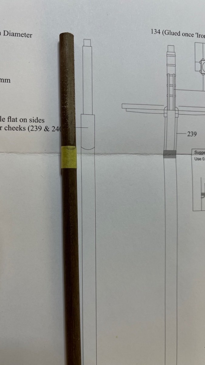
Hi Chris,
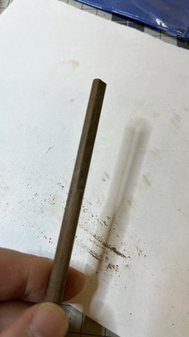
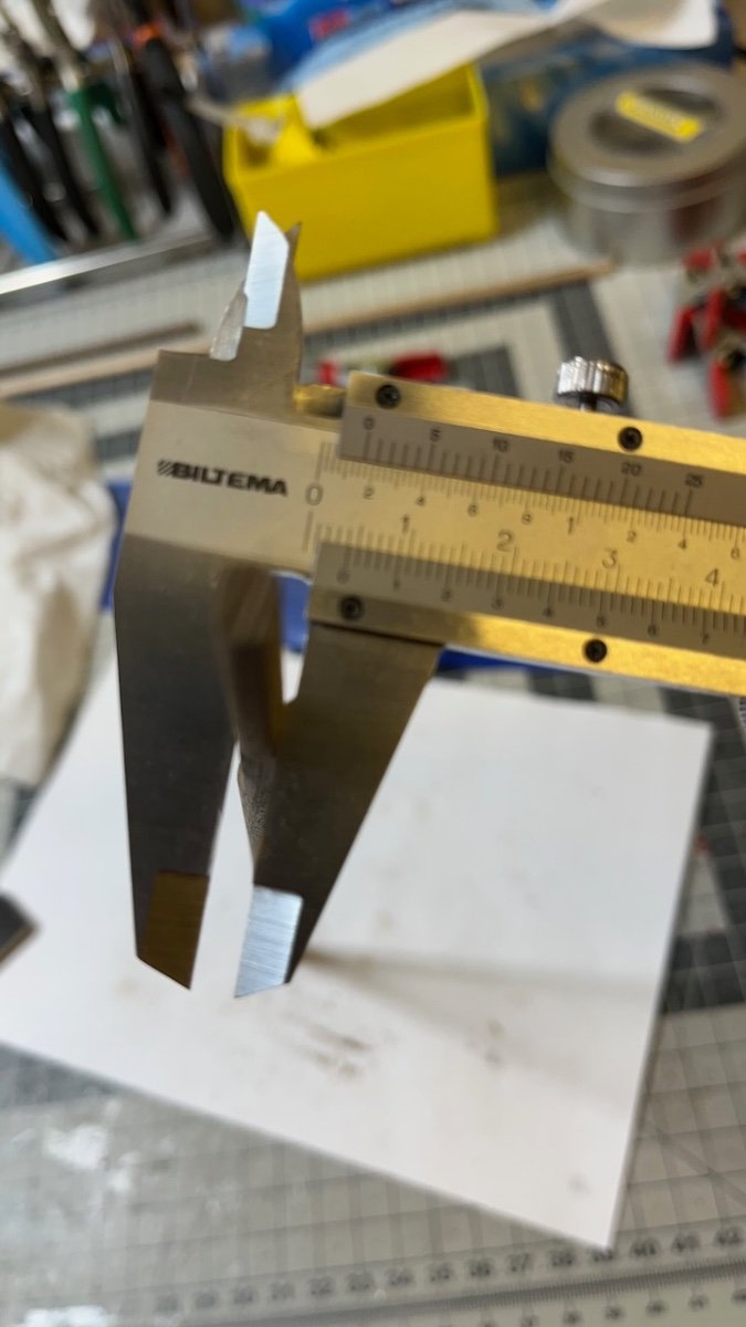
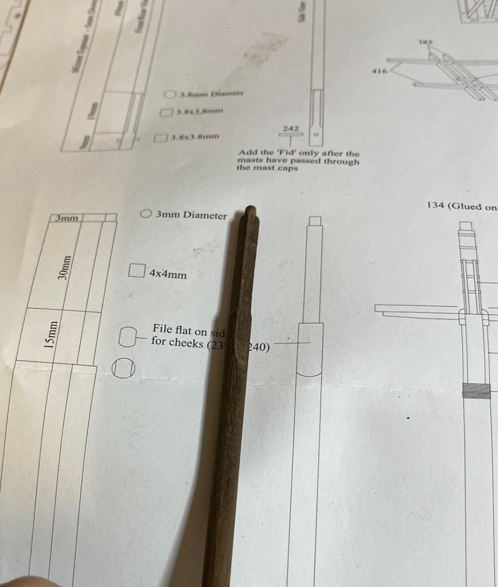
The hole in the mast cap is too small to push the topmast and that's my issue. Mast cap hole is 4mm diameter while the topmast I need to push it through has a 5,2mm diagonal thickness, when I sand it to a 3.8m x 3.8mm square.
-
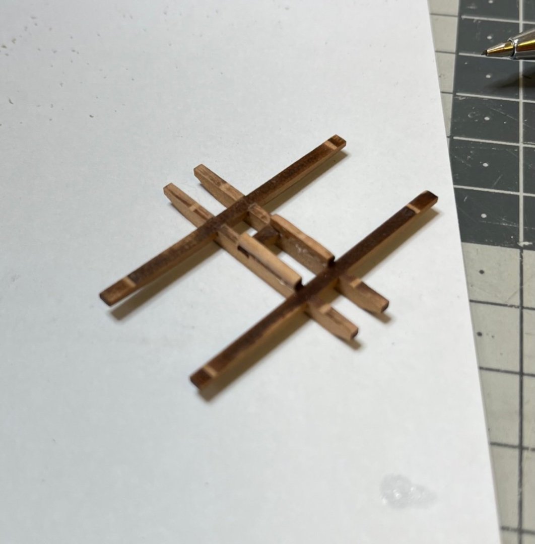
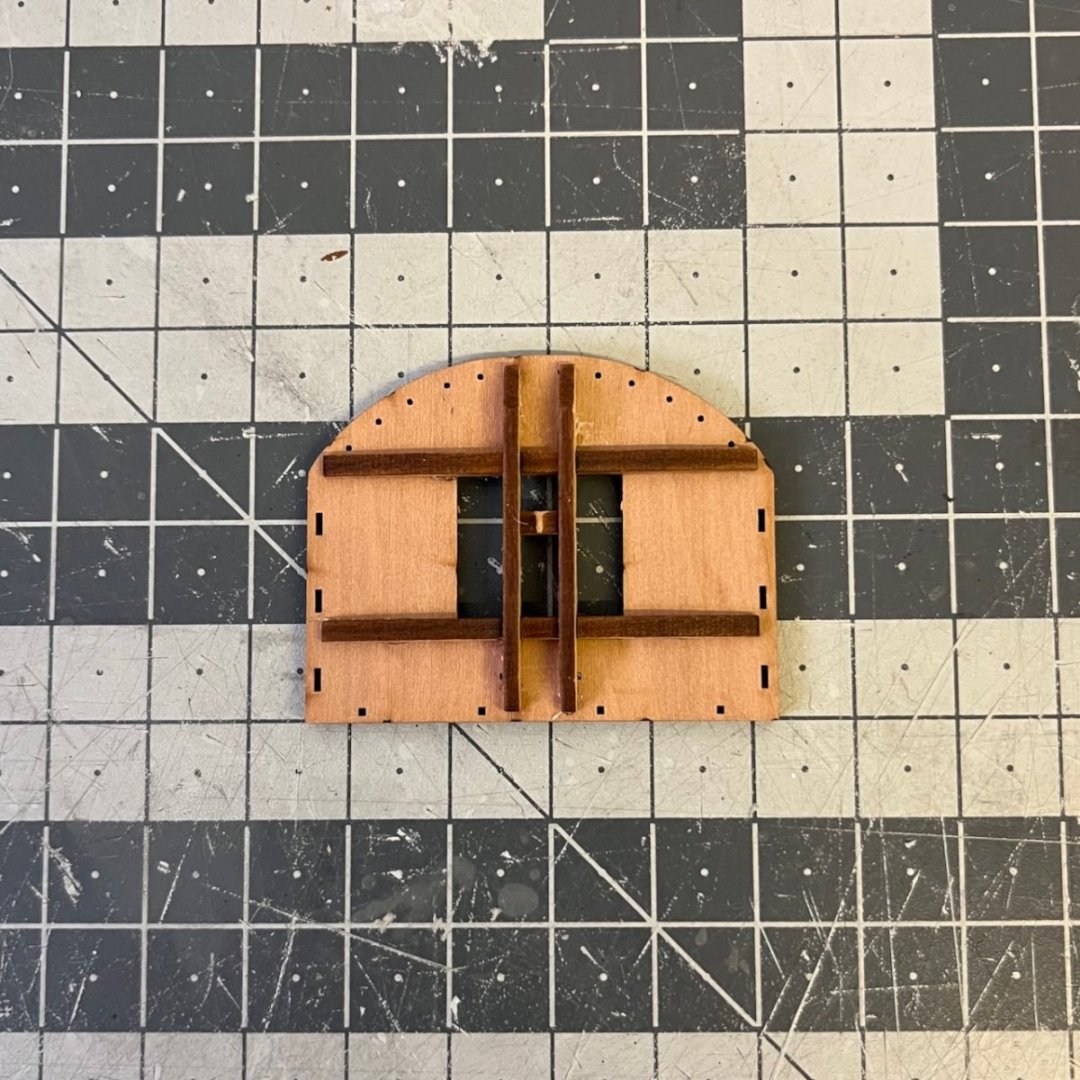
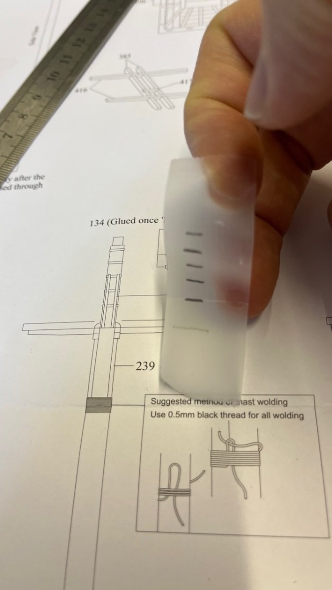
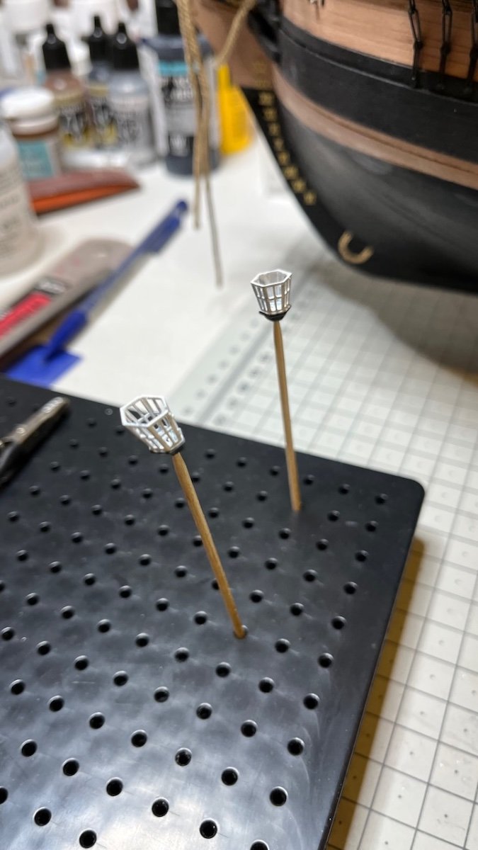
Now I have a problem. I appreciate any assistance:
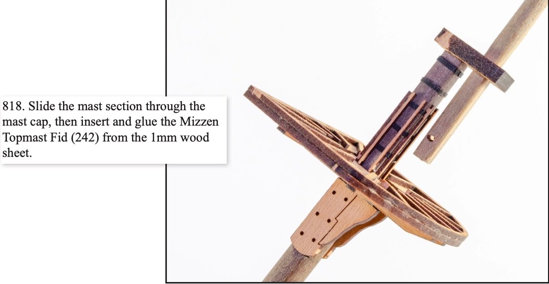
I am building the Mizzen mast and at this stage I am supposed to slide the Mizzen Topmast through the Mizzen Mast Cap as in this instruction.
Photo 681:
I already glued the cap in the previous step and it looks like this now (photo from the instruction manual):
Photo 682:
Photos 683-684: However it doesn't seem possible to slide it, as the lowest part of the topmast has a diagonal width of 5,2mm (or even 5,4mm if you calculate it mathematically), while the cap (part 470) is only 4mm in diameter.
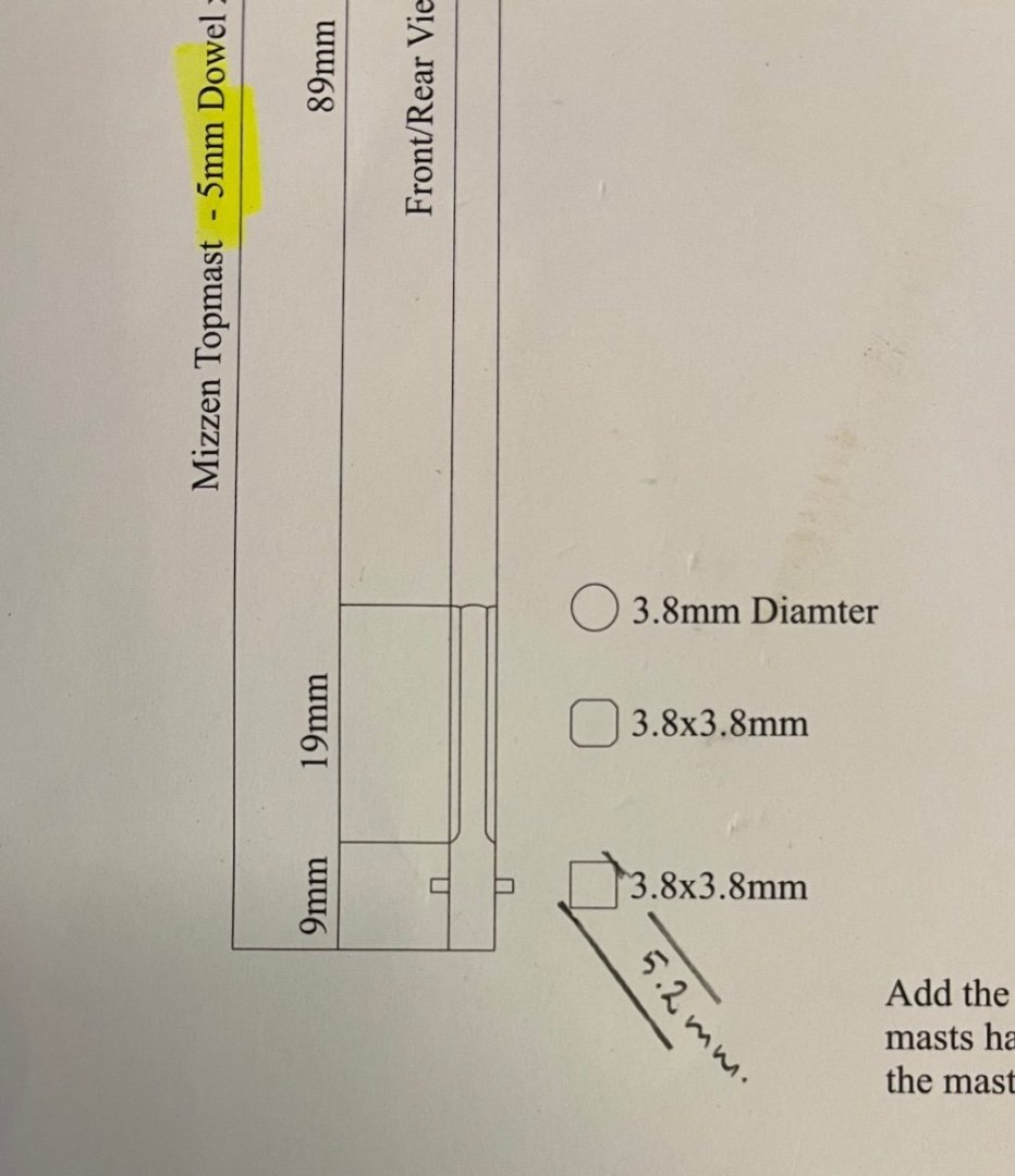
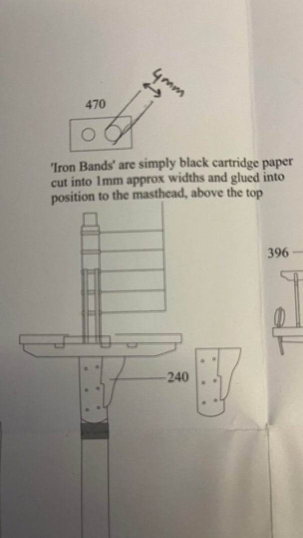
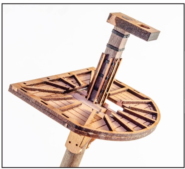
Photo 685: This is how it is supposed to look like afterwards: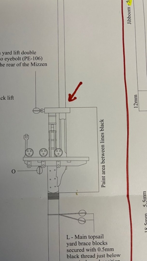
What am I supposed to do? If I enlarge the cap hole diameter to 5.2mm then I worry that it will look ugly since it will be only a 3,8mm diameter rod passing through it. The options I see are:
- Cut the mast from where it will be inside the cap and install it in two pieces, or
- Make the lower part also a round 3,8mm diameter and slide it in like that, in this case it will be a deviation from the originalAll advices welcome.
-
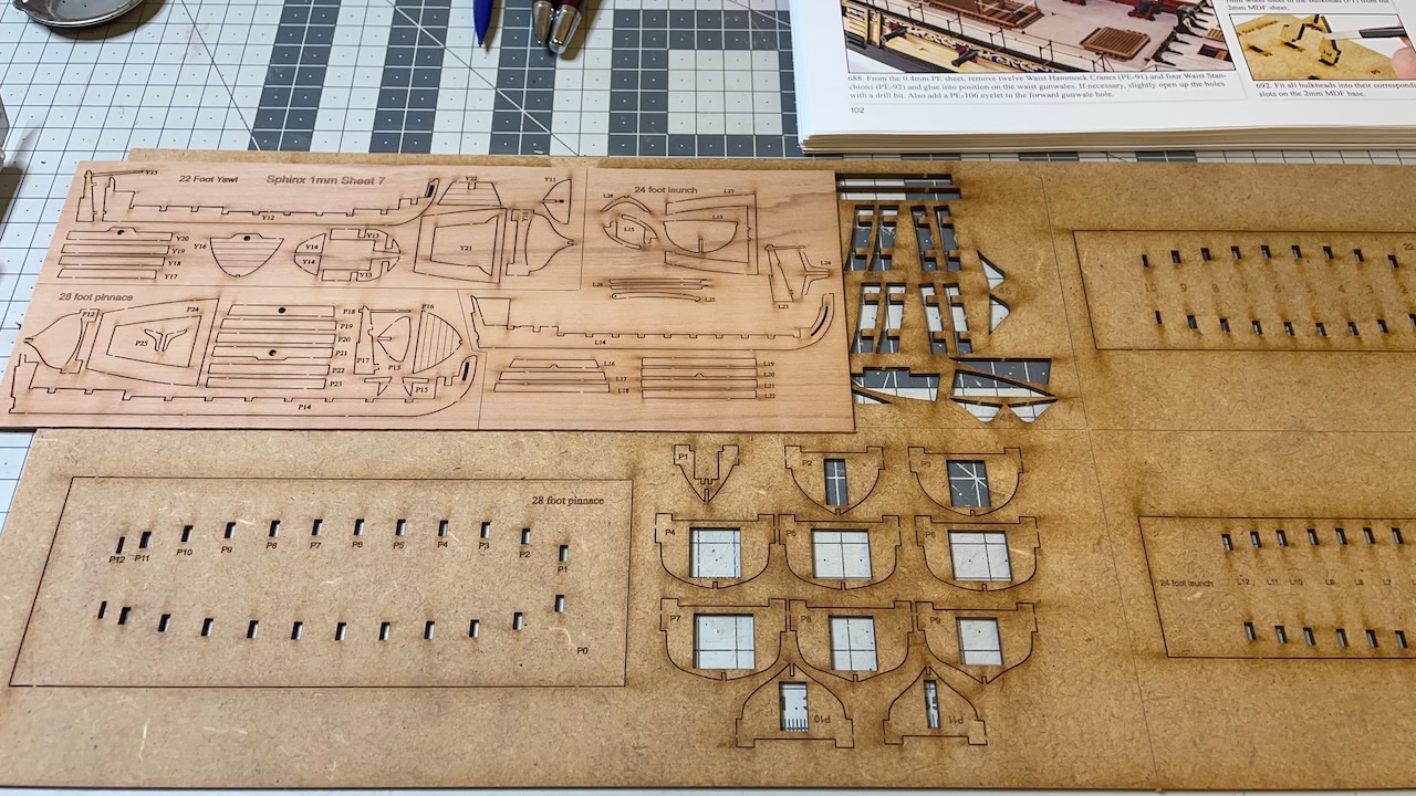
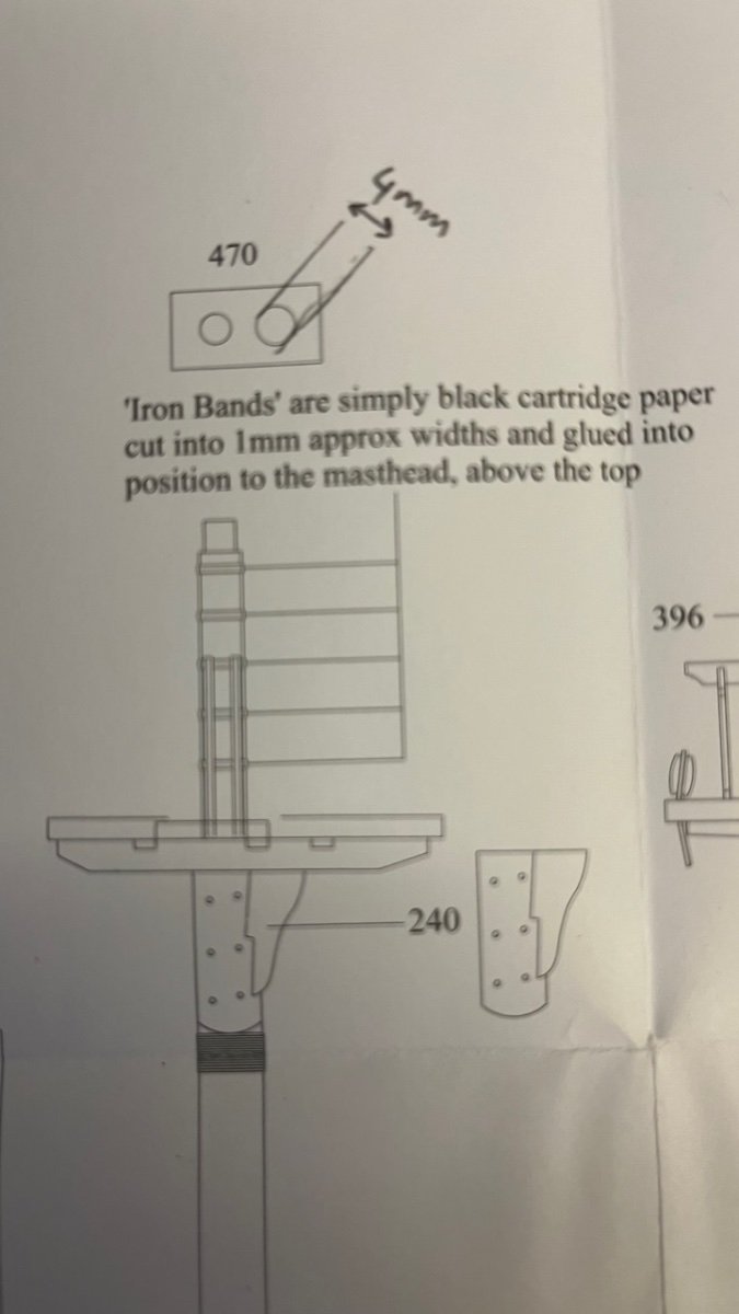
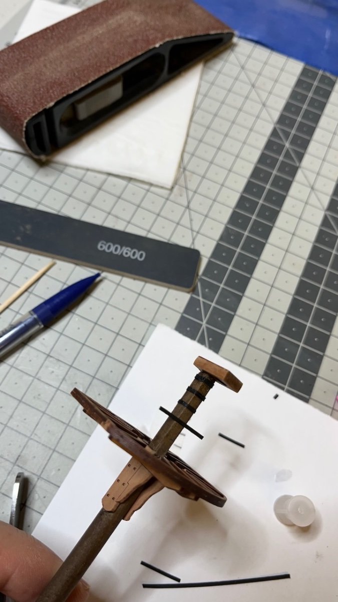
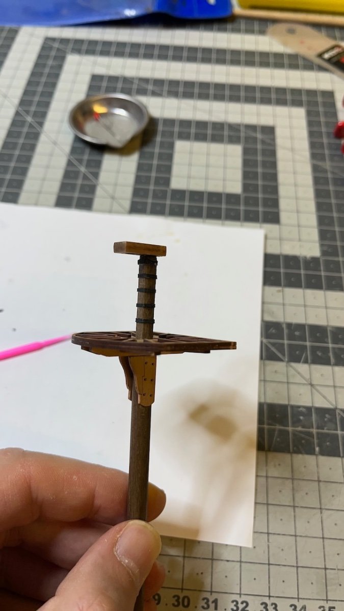
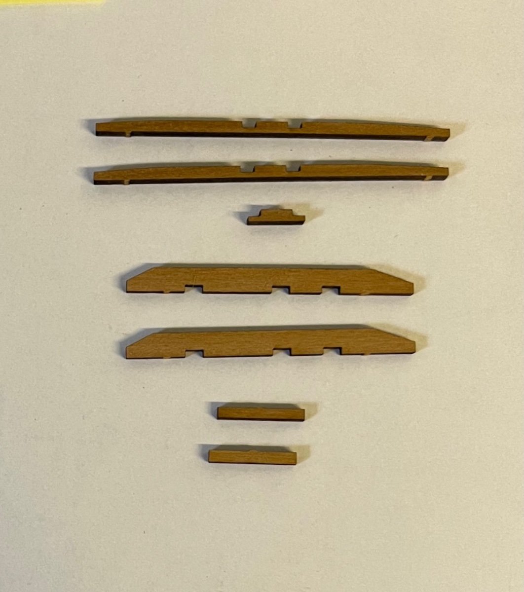
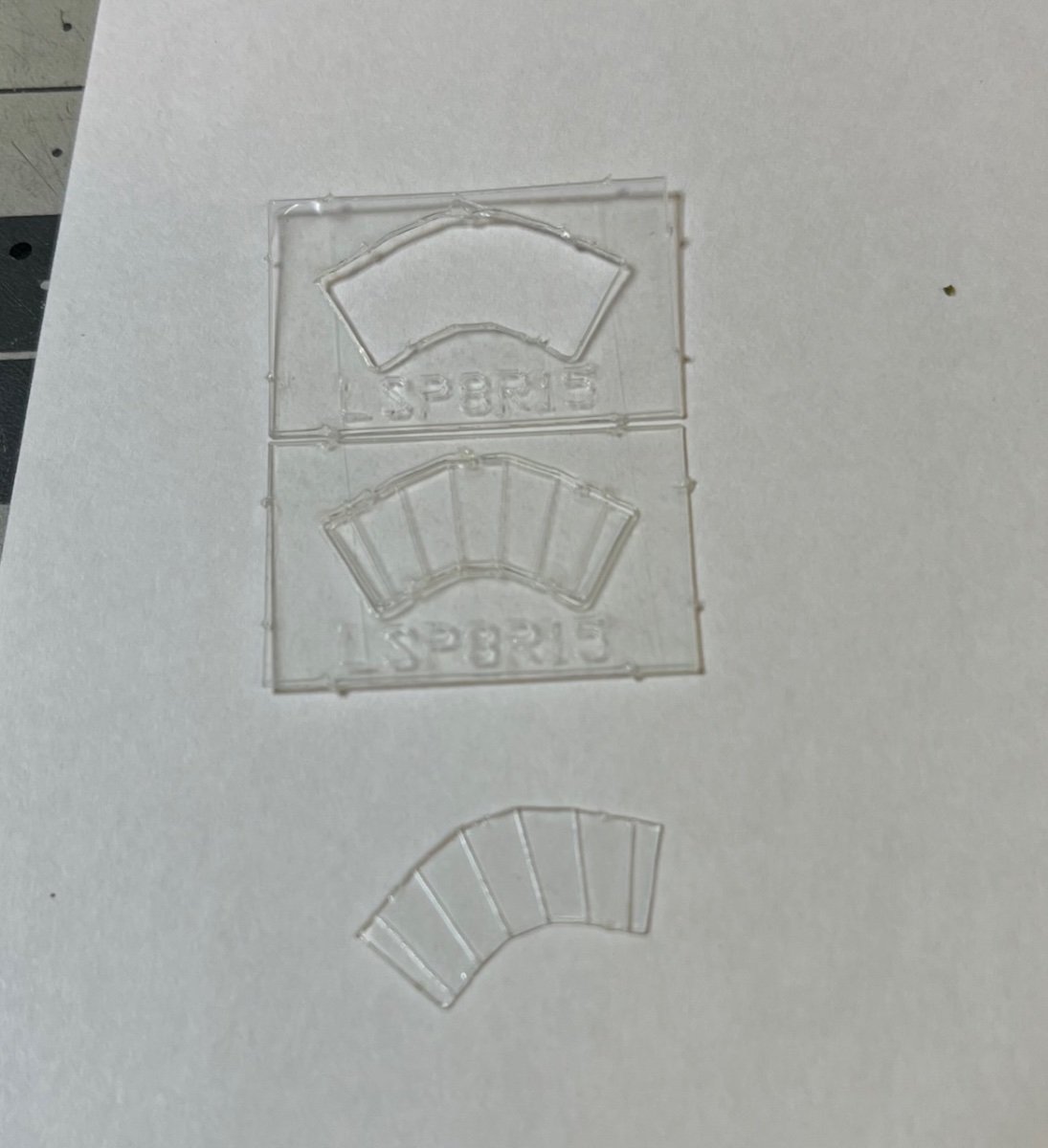
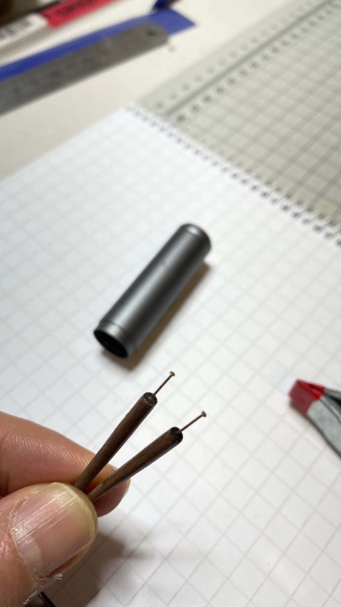
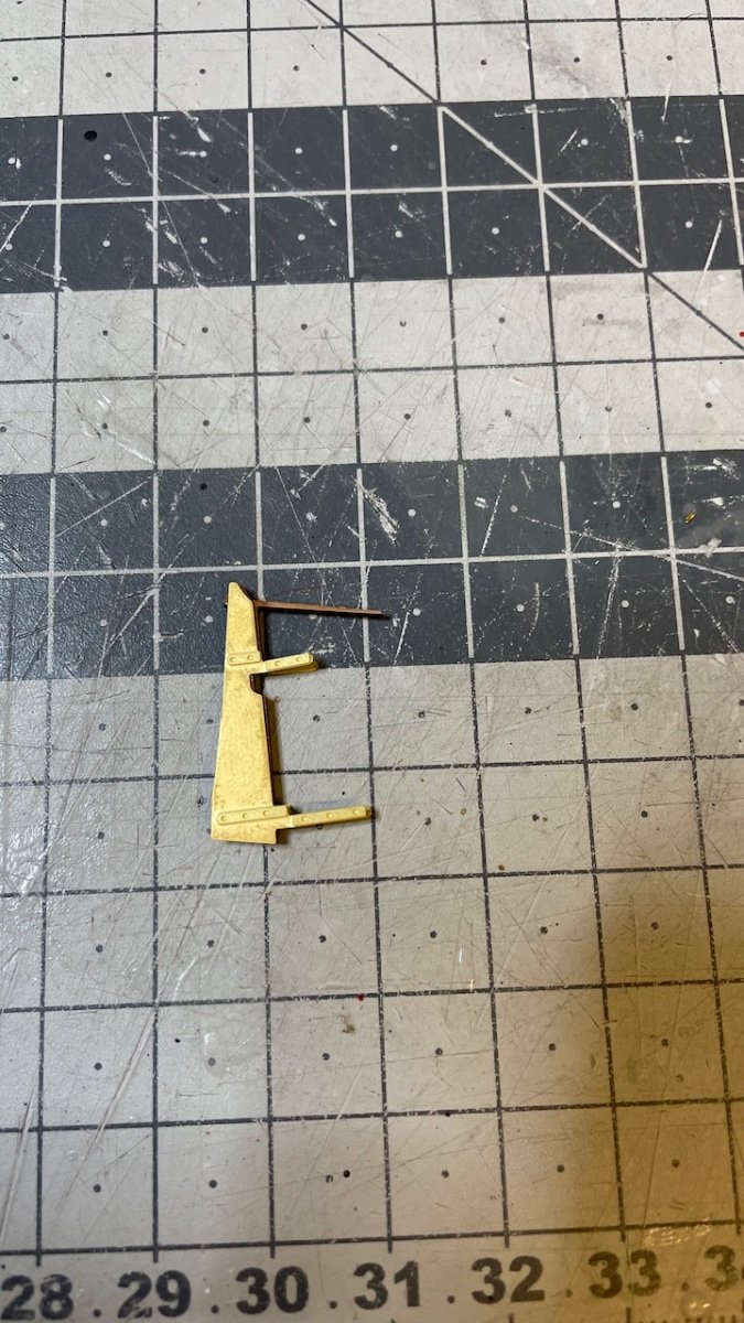
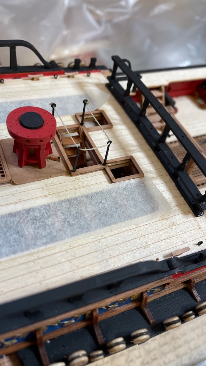
Photos 676-680: Iron bands (made of black paper sliced in 1 mm width) and mizzen mast battens.
For correct positioning I carried the measure from the plan using an invisible tape.
I used CA to glue them on the mast. At this point I am not worried about any discoloration caused by the glue nor about the laser char around the edges as this section will be eventually painted in black.


That's all for now. Thanks for watching!
-
-
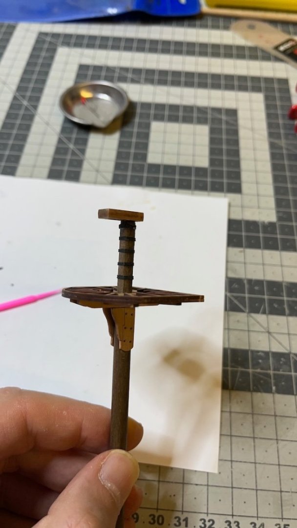
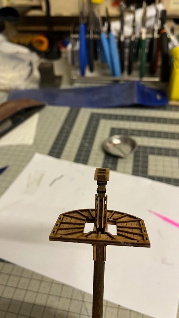
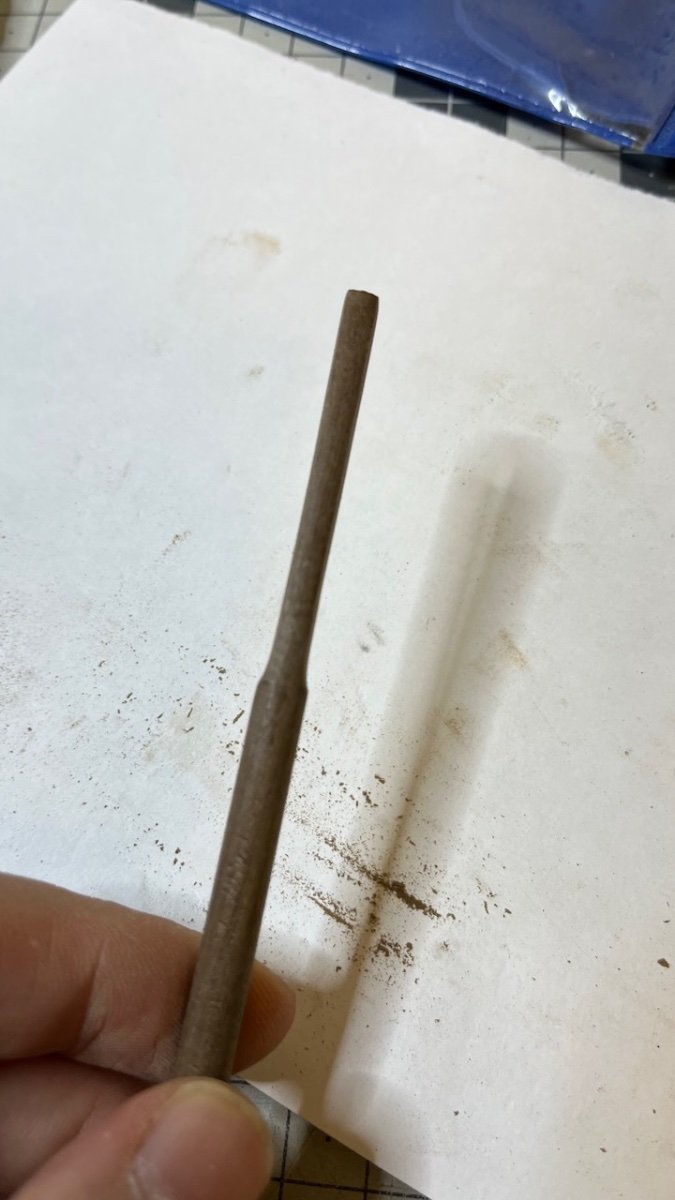
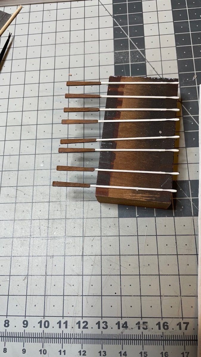
Photos 665-672: Mizzen mast lower section. Though it doesn't have tapering all along, the top part of this section has several change of shapes. Below is a sequence of photos showing the progress.
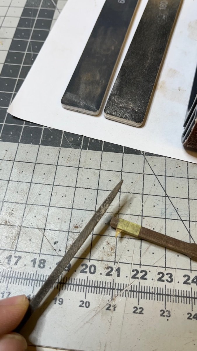
I used rough sanding block, fine sanding sticks, file, masking tape and caliper as you'll see in the photos.


-
Build days 88-89: 3 hrs / Total 201.5 hours
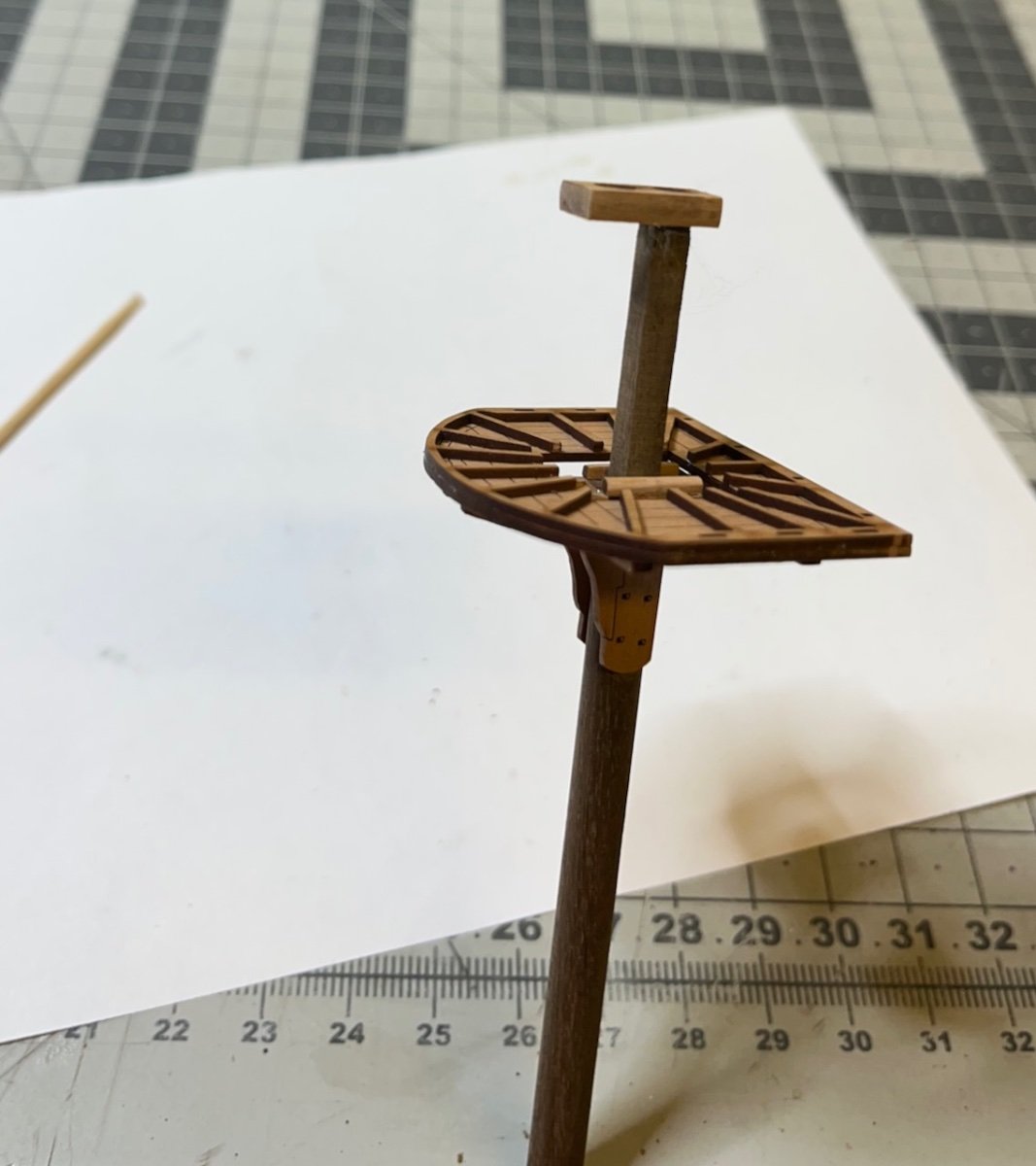
Hitting the 200 hour milestone, now the Mizzen mast construction commences.
Every single step in these constructions use the plan as a reference. It is essential for correct alignment of the parts. You need to check everything from all axes (side, front, back) before gluing anything.
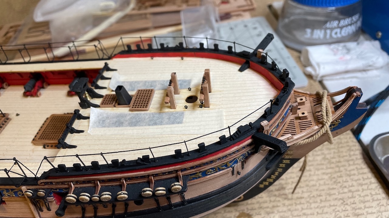
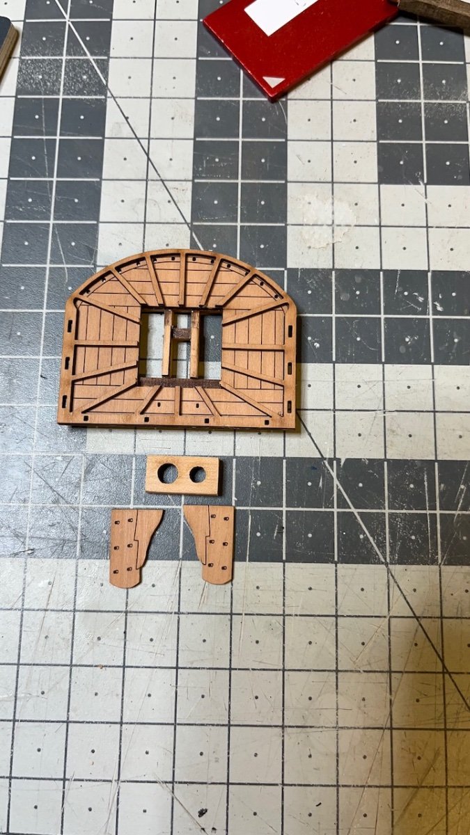
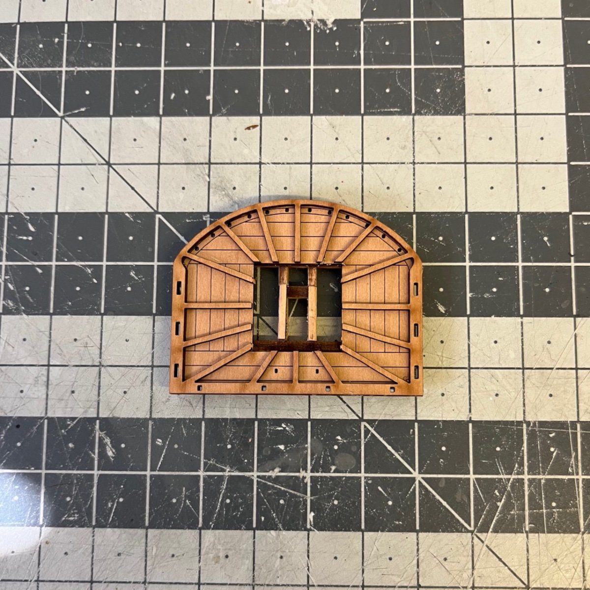
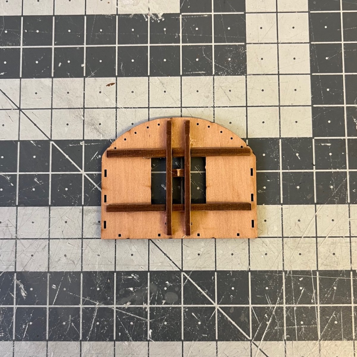
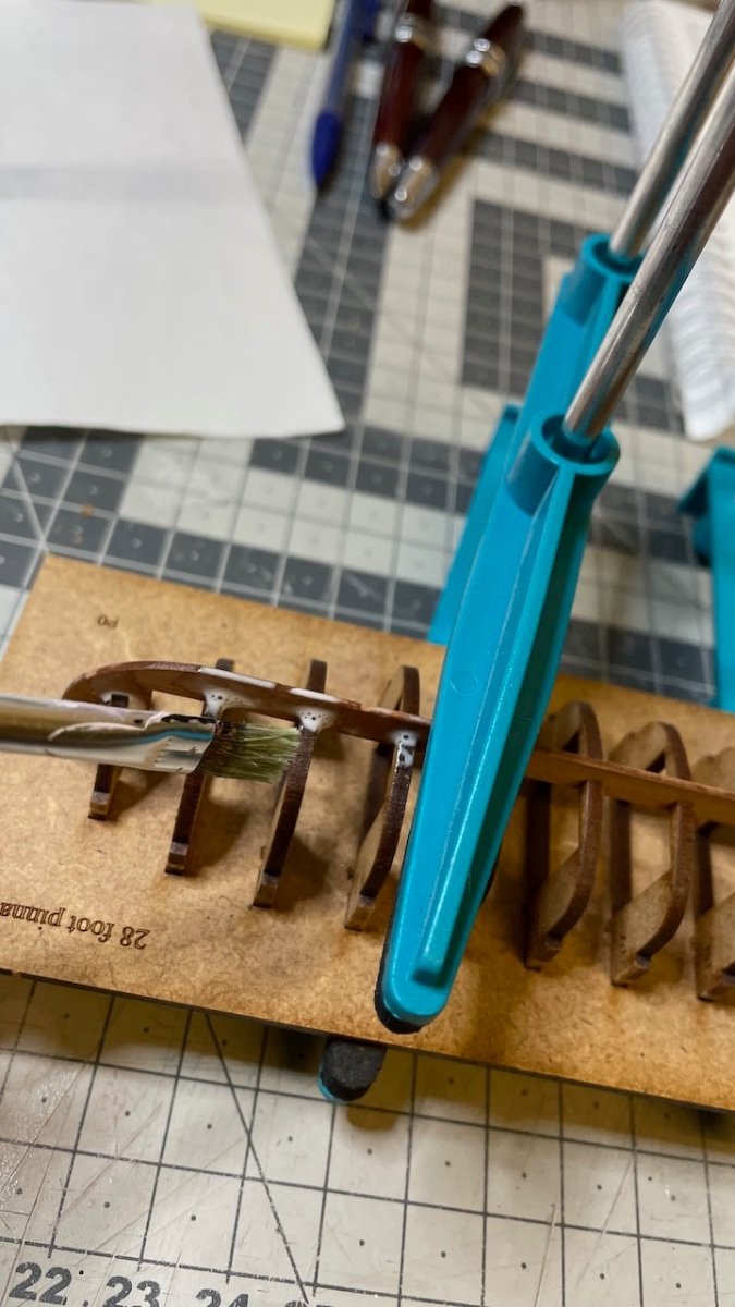
Photo 659: Starting with the platform. The part looking like an imperial sun on the lower right is actually a scrap of the one on its left
")
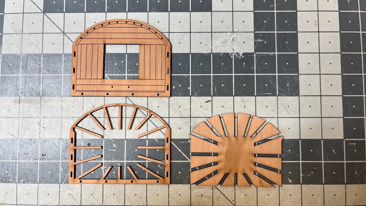
Photo 660: I tried to use minimal amount of glue for assembling the two parts, in order to avoid any stains. Micro drops on the tip of the ribs and a few drops around the edge.
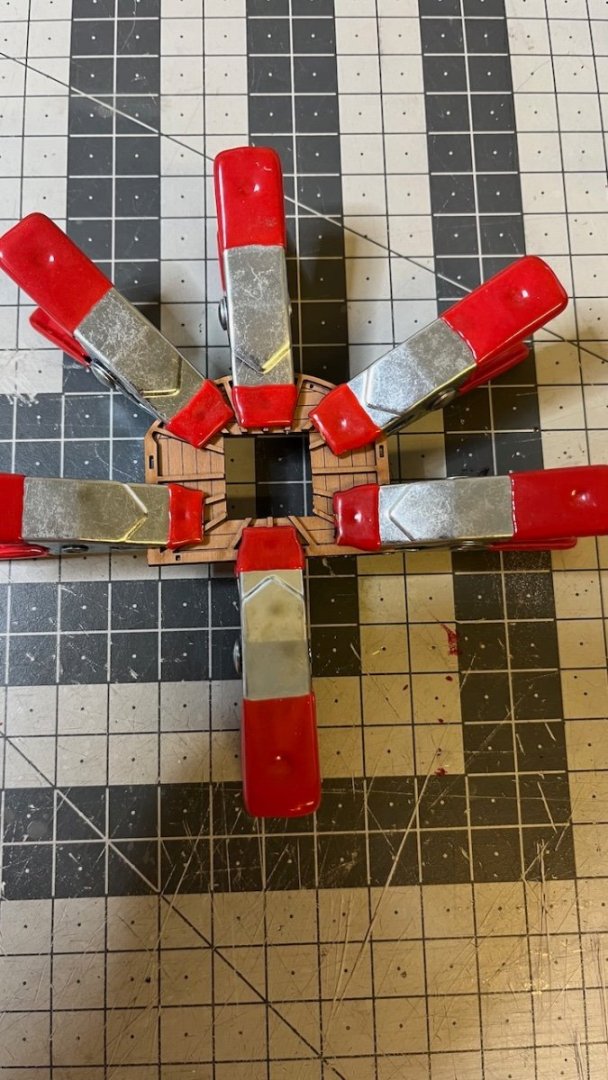
Photos 661-662: Mizzen cross-tree assembly. After dry fitting, it was aligned so well, I didn't want to remove them for applying glue, so instead I brushed diluted glue on the joints.

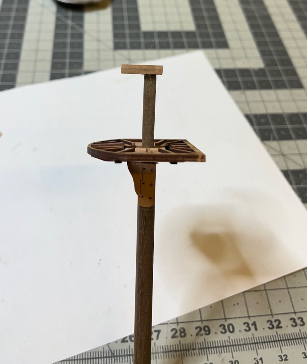
Photos 663-664: Complete platform assembly

-
-
-
-
Build day 86: 1 hr / Total 198,5 hours
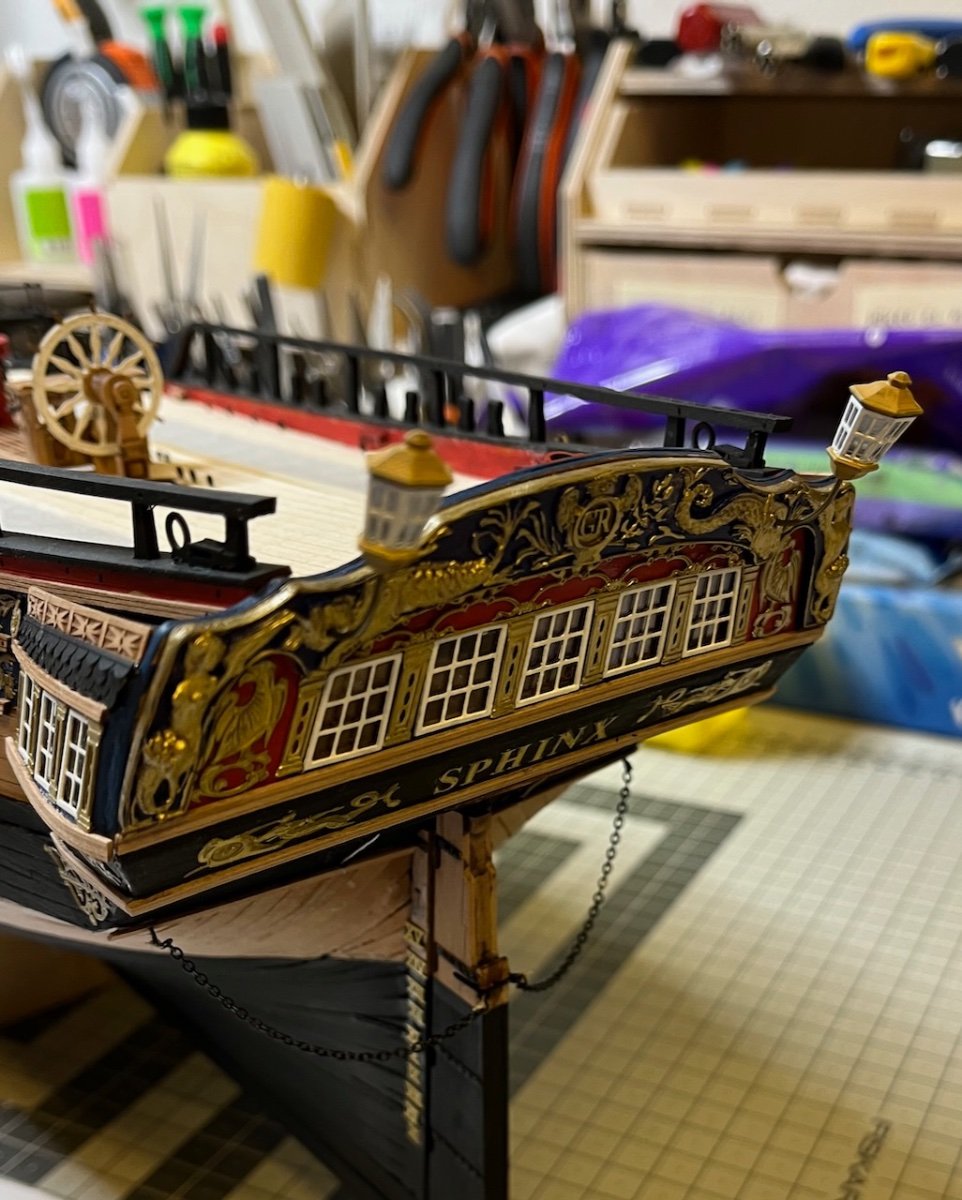
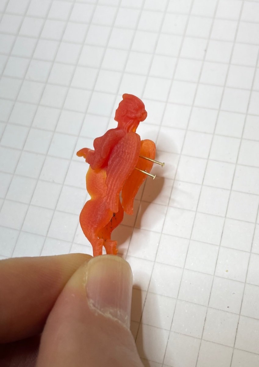
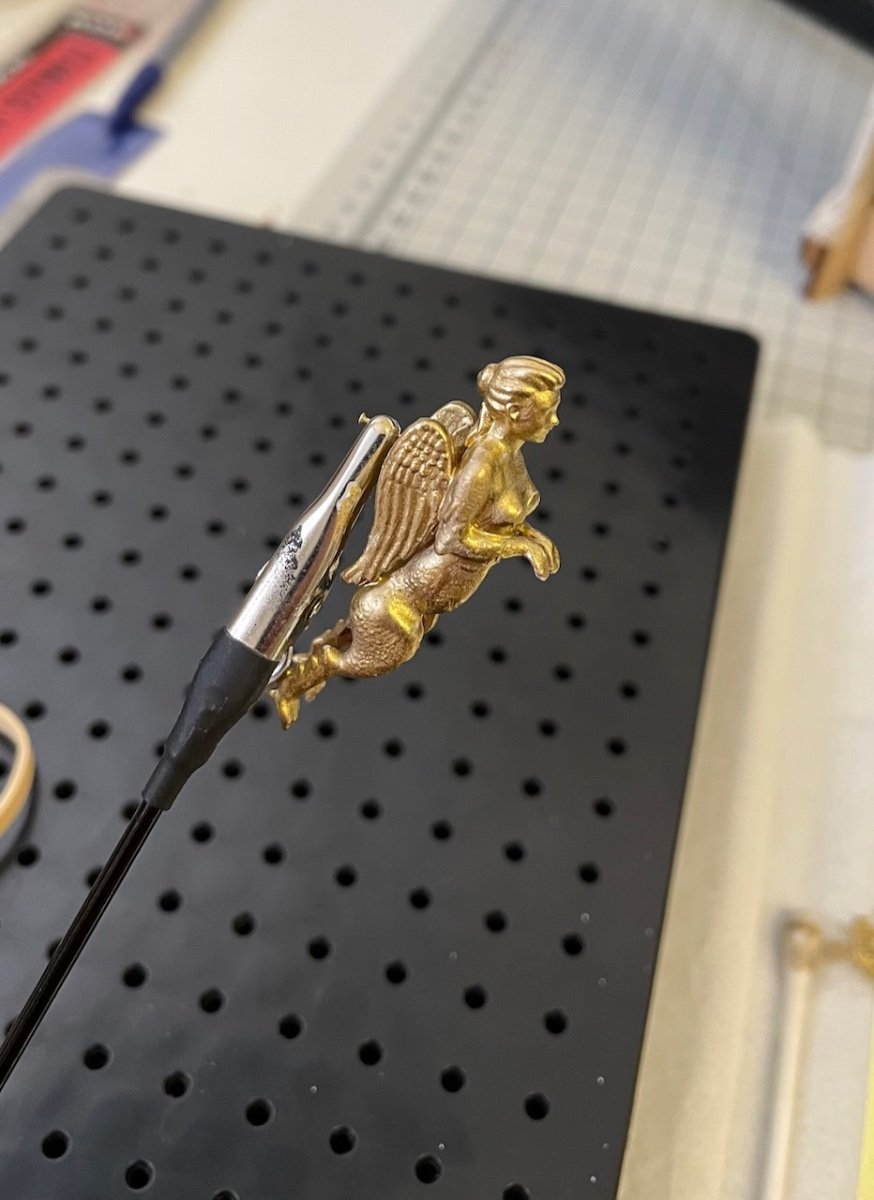
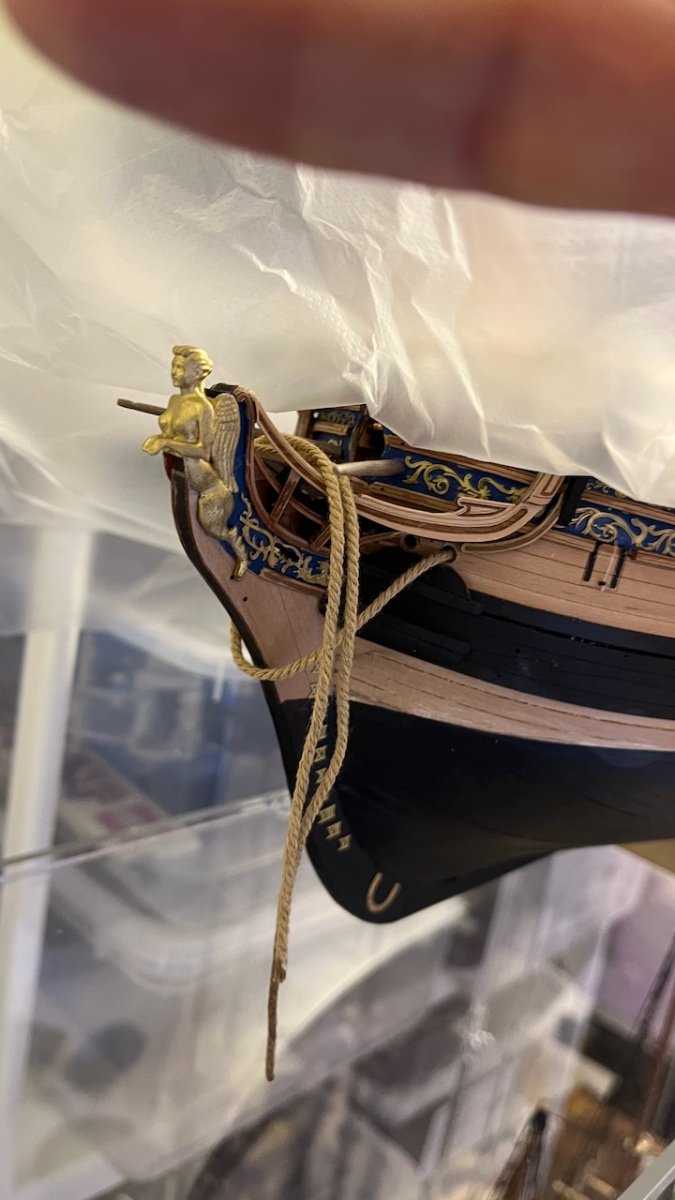
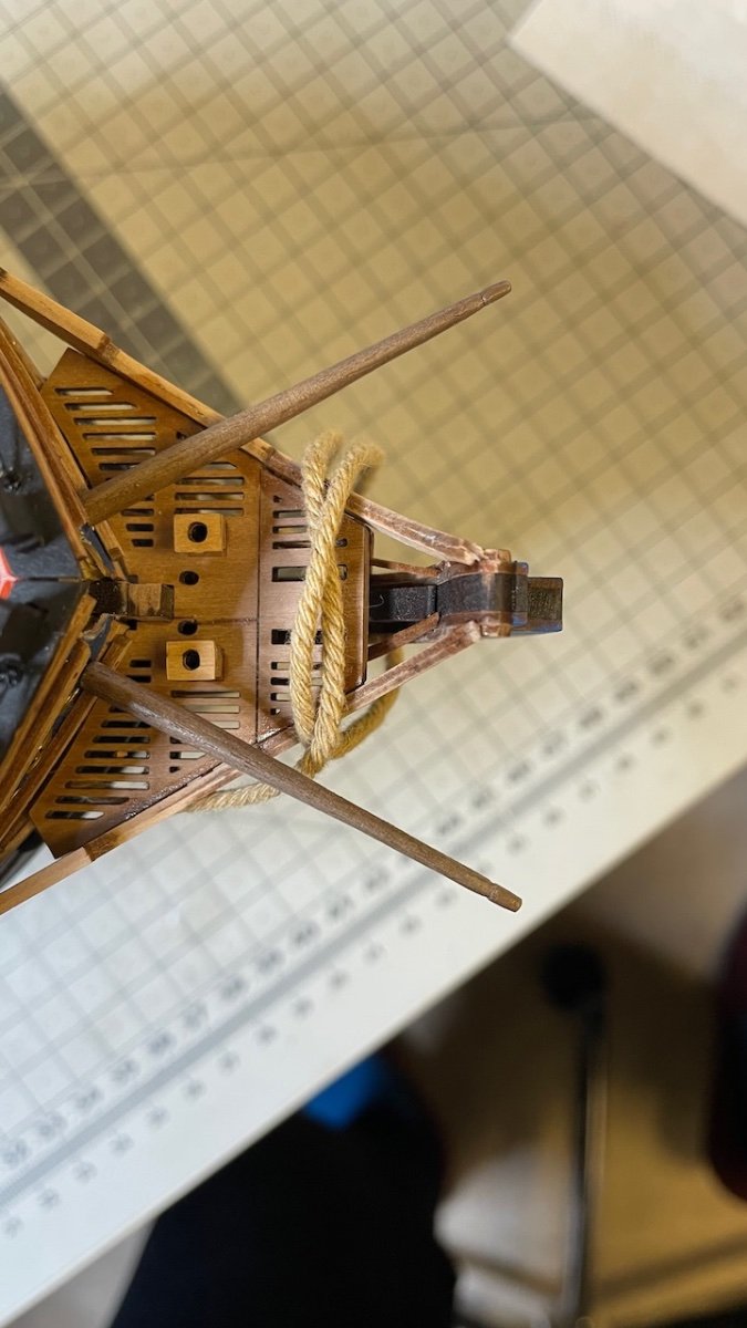
After the boats, the hull is back on the table for completing three details left before starting masts and yards: Boomkins, the figurehead and the lanterns.
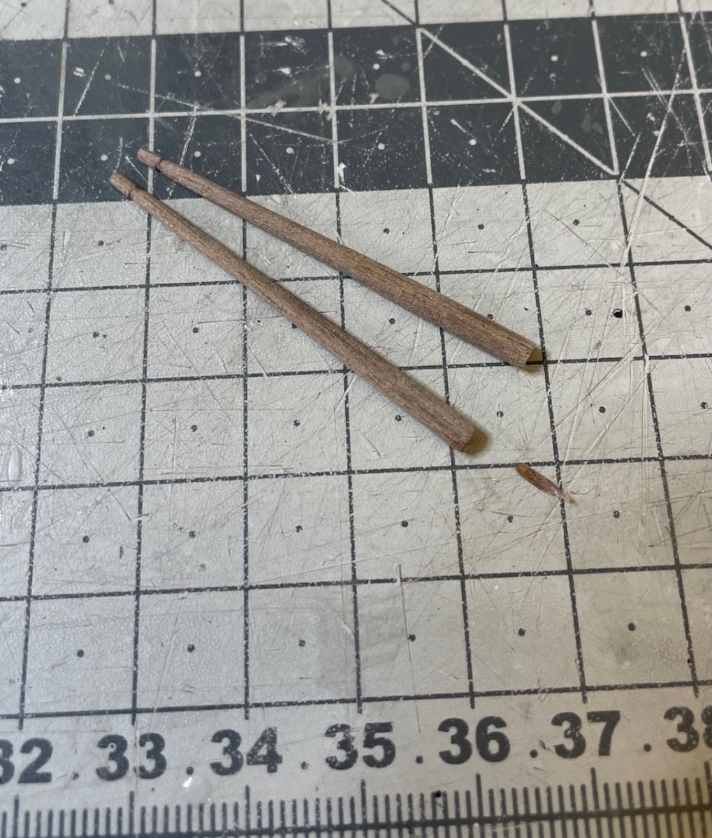
Photo 648 : boomkins are made of 46mm long 3mm diameter walnut dowel, tapered to 1mm thickness at the other end, as per the plan.
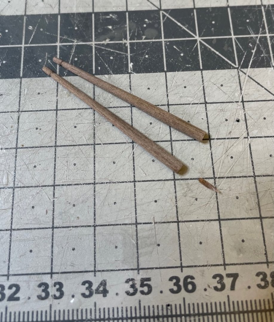
Photo 649: I used my handheld Proxxon and a sheet of sand paper for tapering.

Photo 650: Nails for fixing them to bow (nail tips clipped before doing so)
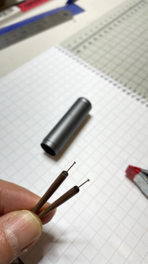
Photo 651: Boomkins in place taking care of the alignments from the plan.

-
Build Days 82-85: 7 hours / Total 197,5 hours
Photos 643 - 646: 22-foot Yawl construction, spread to 4 build days from April 13th to April 16th, altogether 7 hours. Build sequence goes similar to former two boats hence not many details worth sharing here either.
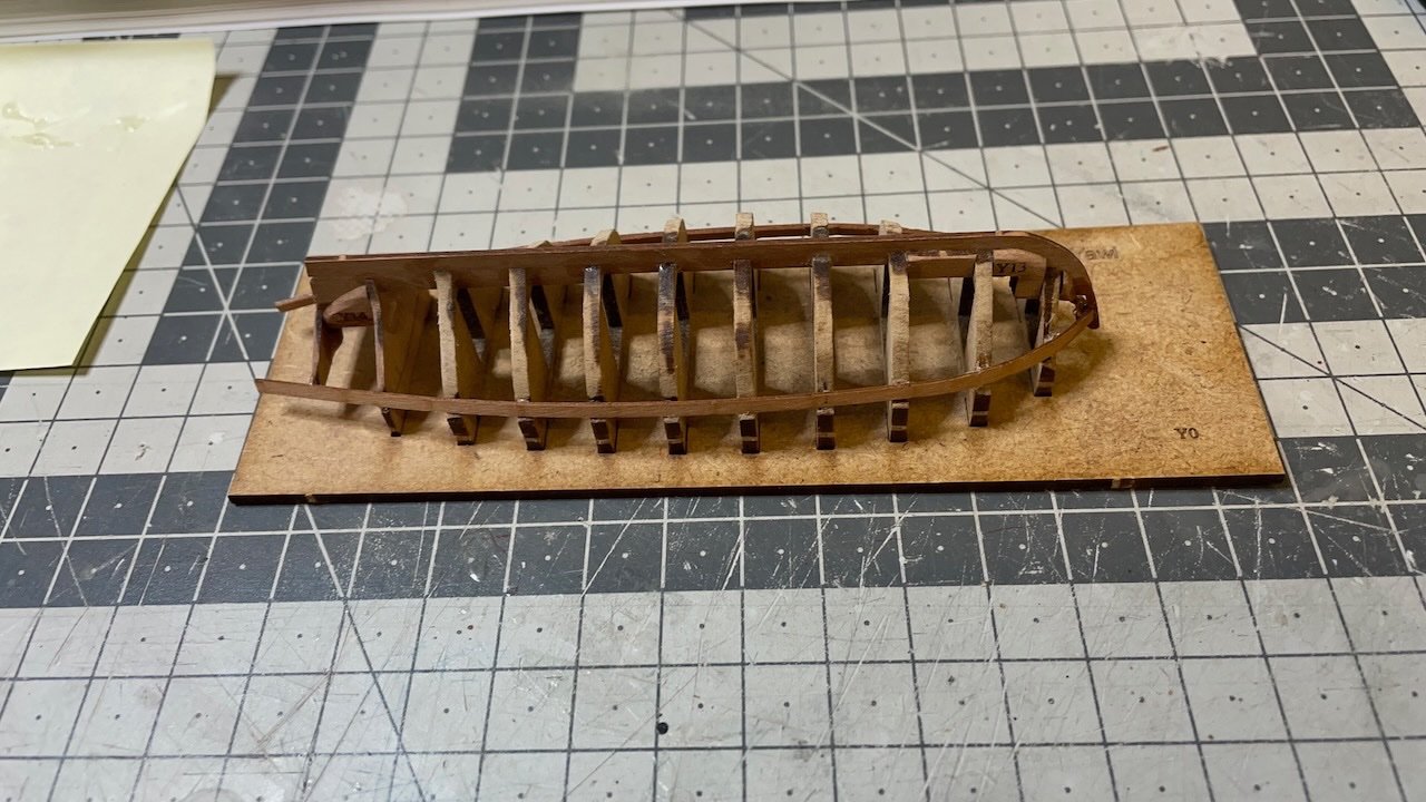
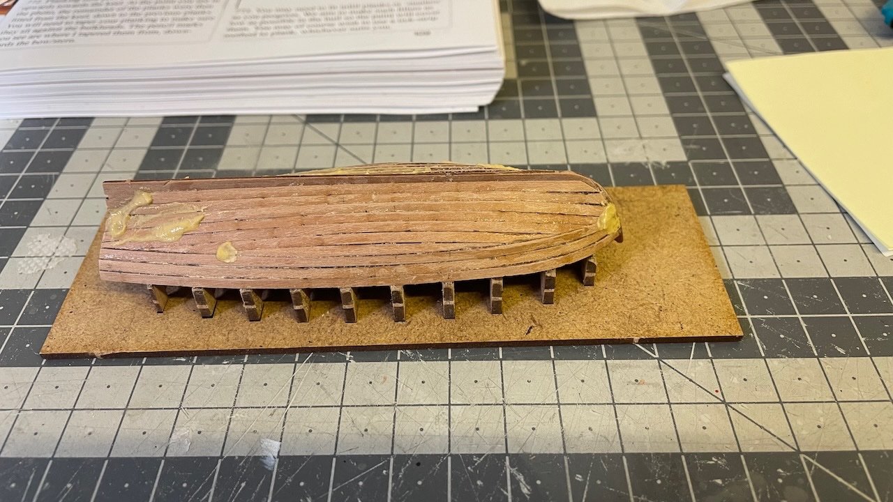
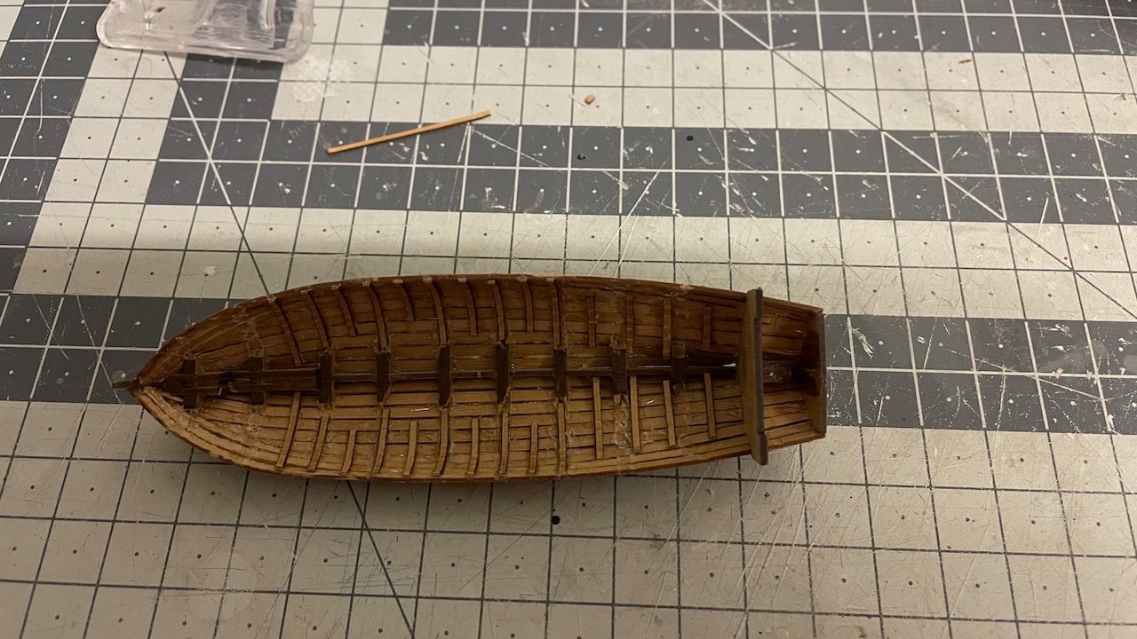
Photo 647: All boats safely in a box, waiting to be mounted permanently, which will take place after some progress with rigging, as per the instructions.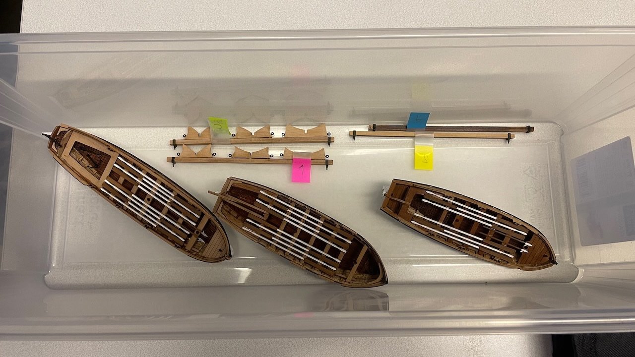
That's all for today. Thanks for watching!- Cirdan, chris watton, Glenn-UK and 5 others
-
 8
8
-
Build Days 76-81: 12,5 hours / Total 190,5 hours
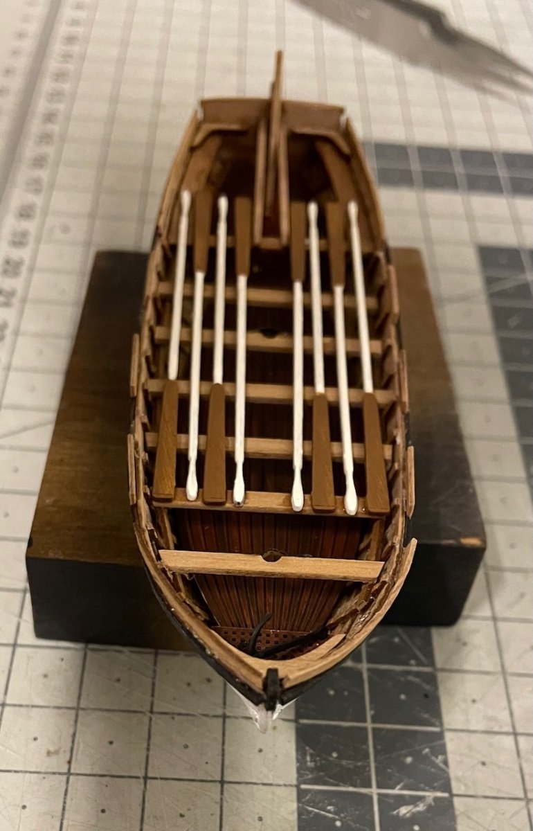
24 Foot Launch construction, spread to six build days from March 23rd to April 10th, altogether 12,5 hours. Build sequence goes similar to the 28 foot pinnace hence not many details worth sharing here.
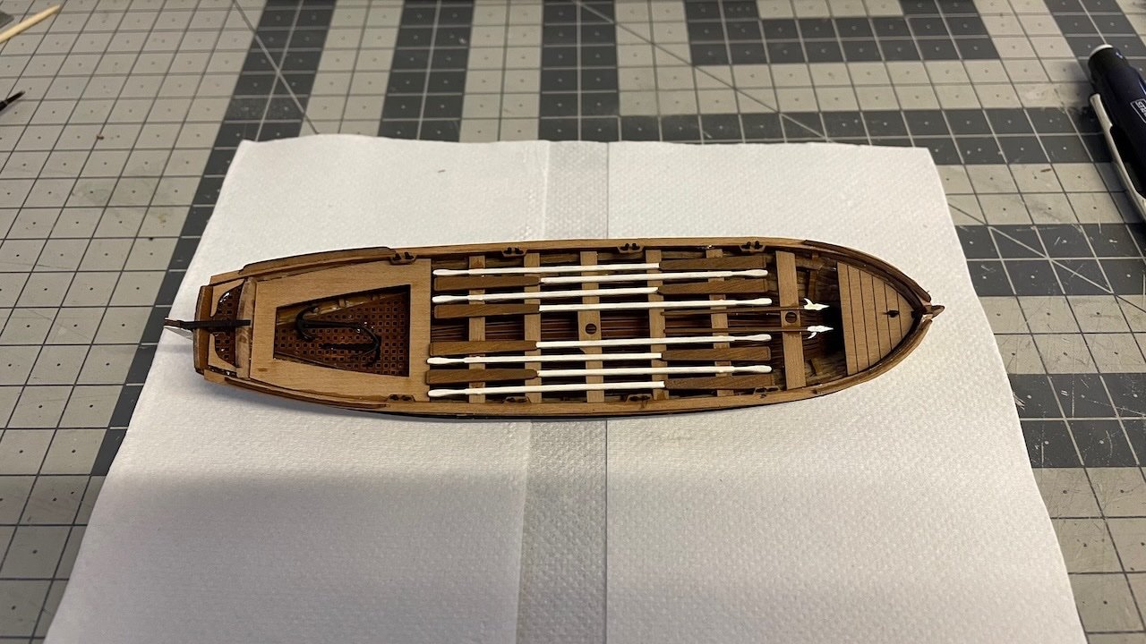
Photo 637: I use this plank bender throughout (bought from Mikromark), which leaves dents on the inner surface, which is partly visible. Using an electric heat bender would give a smoother result but it would take much longer time and anyway this looks acceptable to me.
The number of seat benches in my boat is one less than in the plan. It was due to spacing them maybe 1-2 millimeters wider than normal. Fitting the last bench would look too tight so I just left one out. I also made four openings for oarlocks, one for each of the 4 pairs of oars.
Photos 638-642: Here is the progress.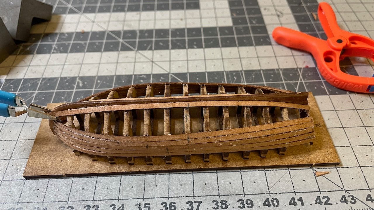
That's all for today. Thanks for watching!
- Cirdan, Haliburton, JeffT and 5 others
-
8
-
-
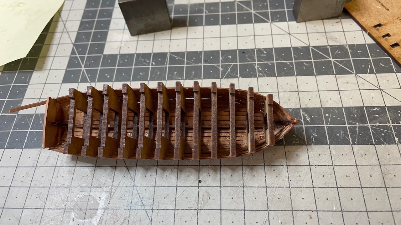
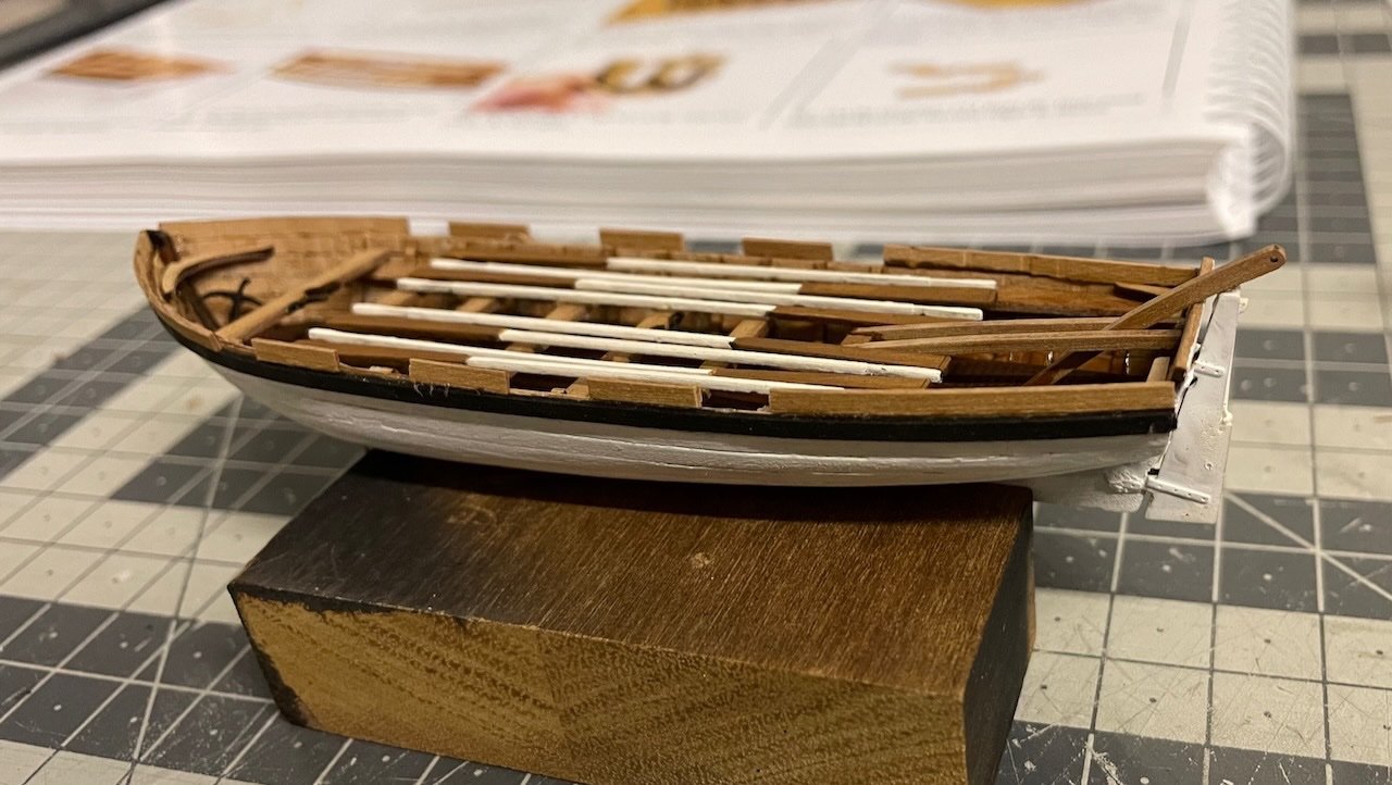
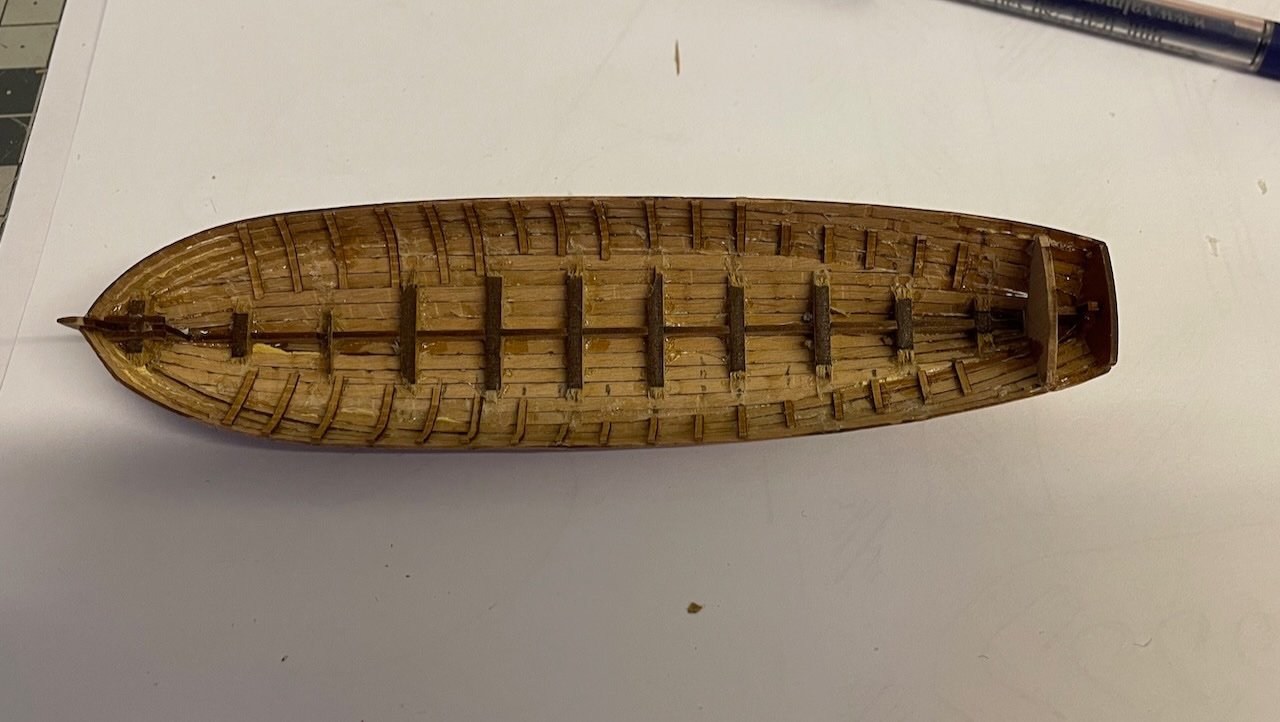
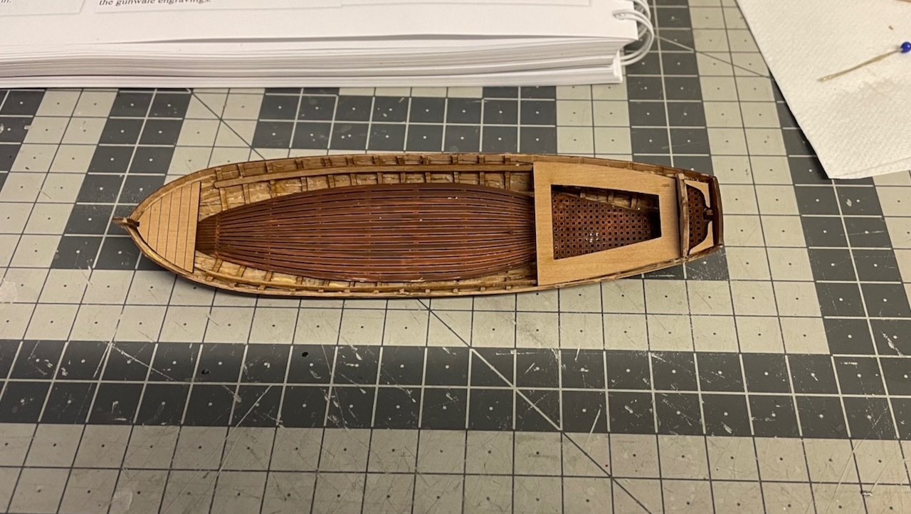
Photos 635-636: Here the 28 foot pinnace ready. Overall I am happy with the result. This is one down and I hope I can apply my learnings to building the remaining two boats. The boats will stay aside for a while in order not to obstruct rigging.
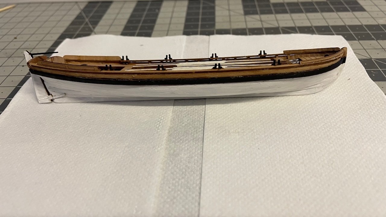
That's all for today. Thanks for watching!
-
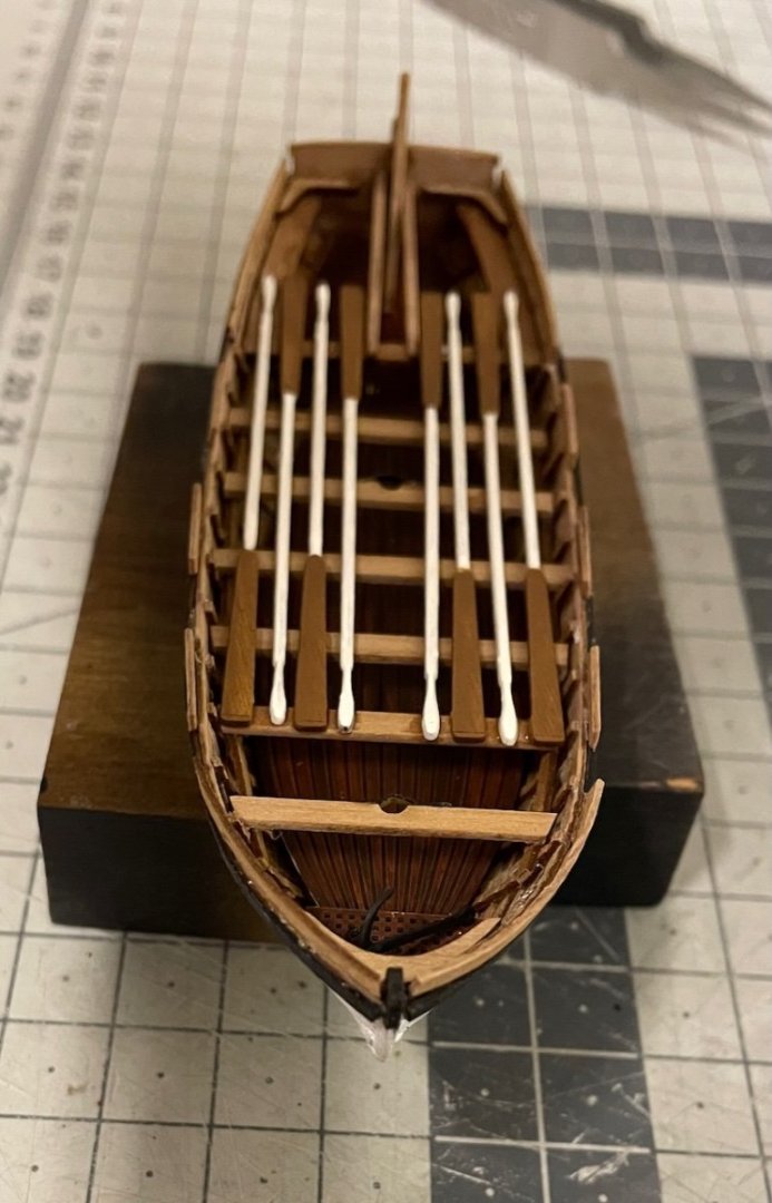
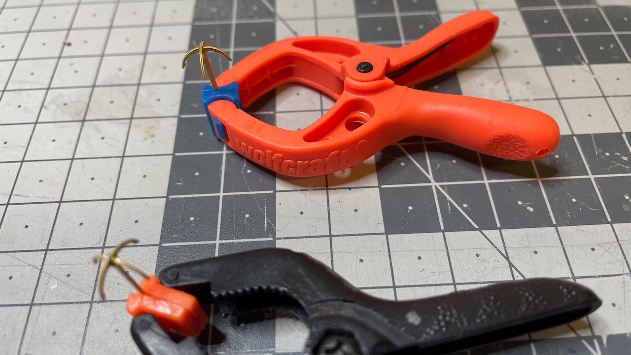
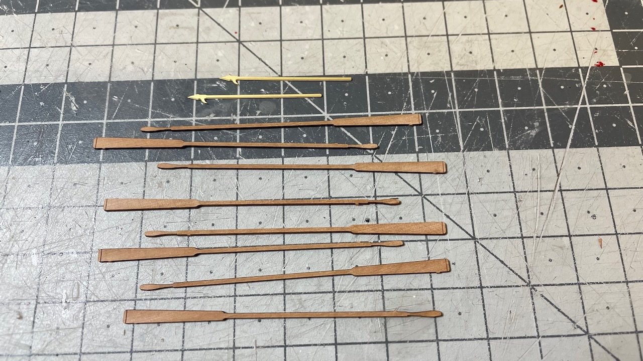
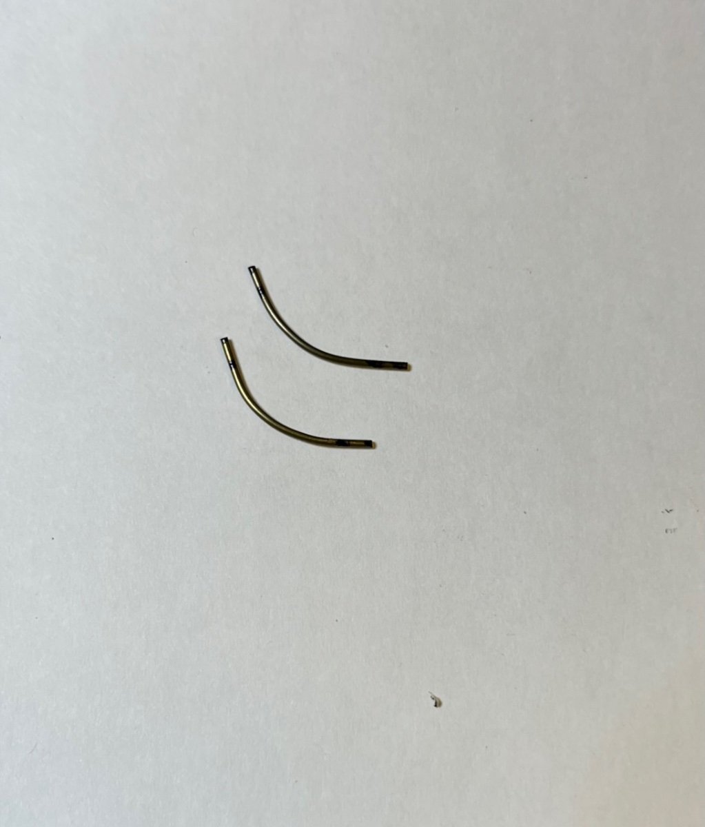
Photos 631-634: Rudder, anchors, oars and spears.


- BobG, KARAVOKIRIS, Cirdan and 2 others
-
5
-
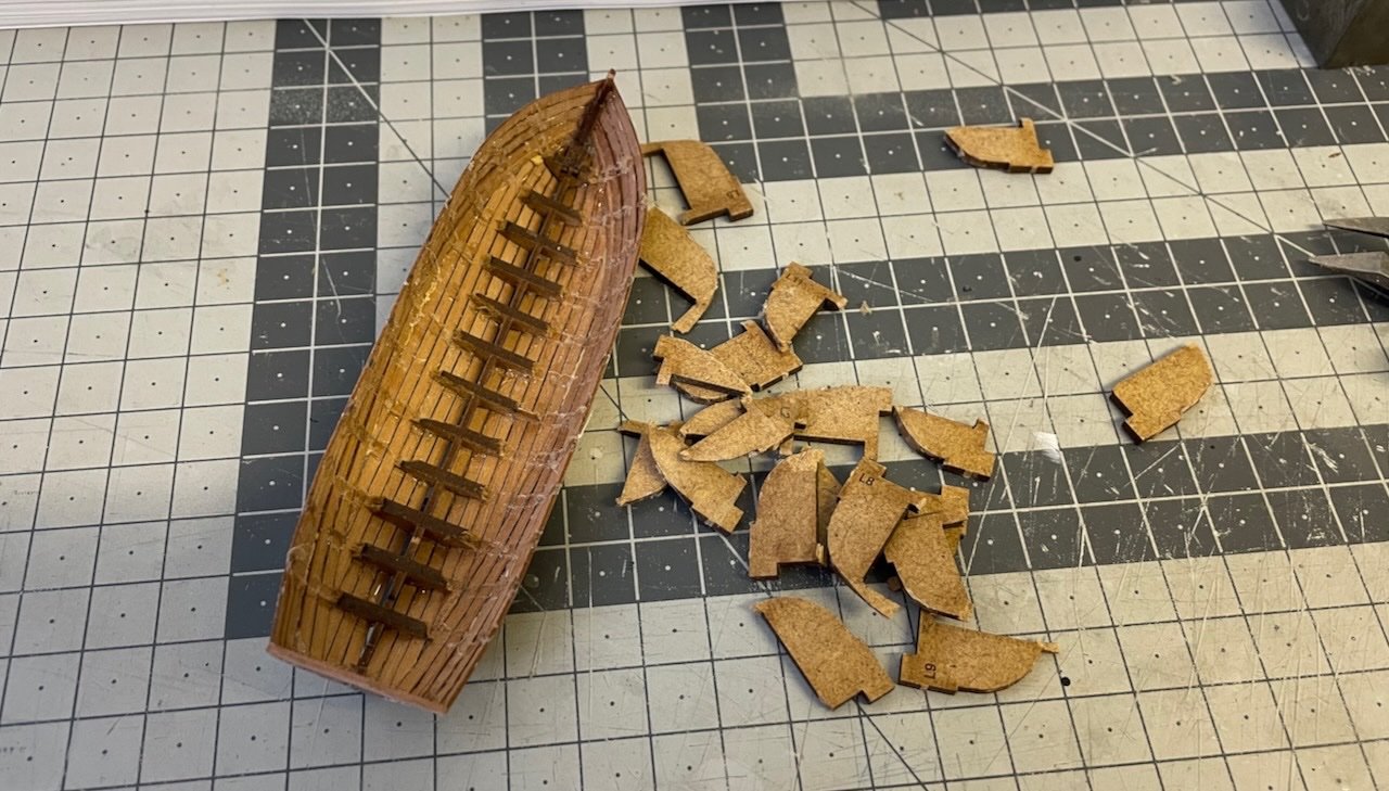
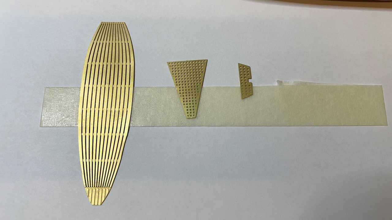
Photos 626-628: Time to remove from the base and rip the bulkheads.
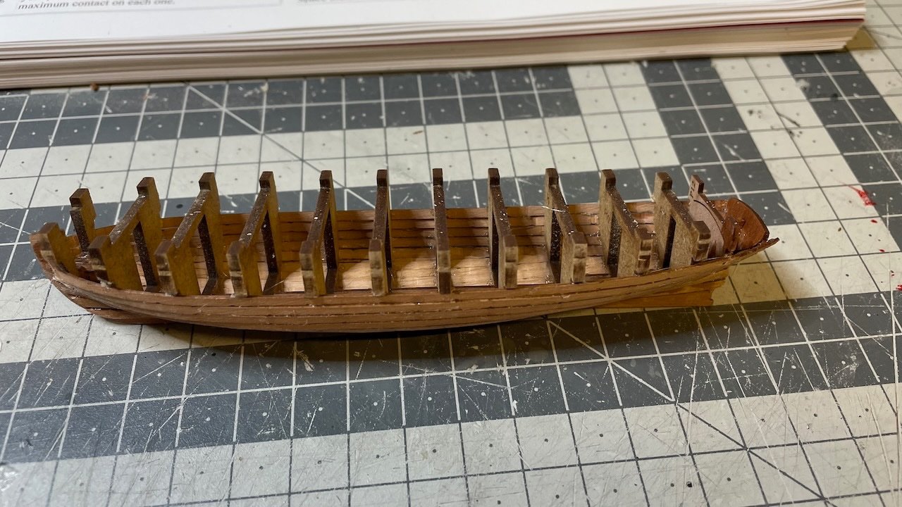
Photos 629-630: Installed the ribs abd the other components seen in the photos. There are some optional paint job steps in the manual, to give a more realistic wooden look to the etched parts, which I skipped. Here I used a brown paint I had in my stock.
- KARAVOKIRIS, Cirdan, mtaylor and 2 others
-
5
-
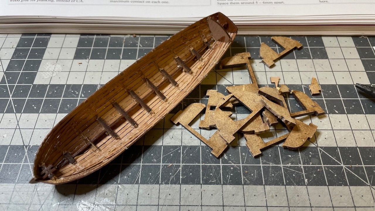
Build Days 72-75: 14 hours / Total 178 hours
It has been a while since my post. Last time I posted I was about to start ship's boats. I wanted to make sure I finished a boat before I share the build process.
I started with the 28 foot pinnace. It took 14 hours to get it ready.
Photo 621: I used the same method of brushing diluted wood glue for fixing the bulkheads to the keel.
Photos 622-624: Left it overnight to let the glue to dry. Then fairing the bulkheads and planking commences.
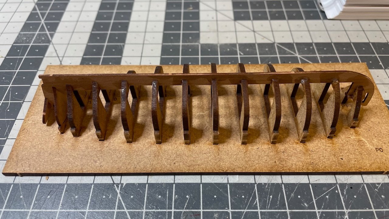
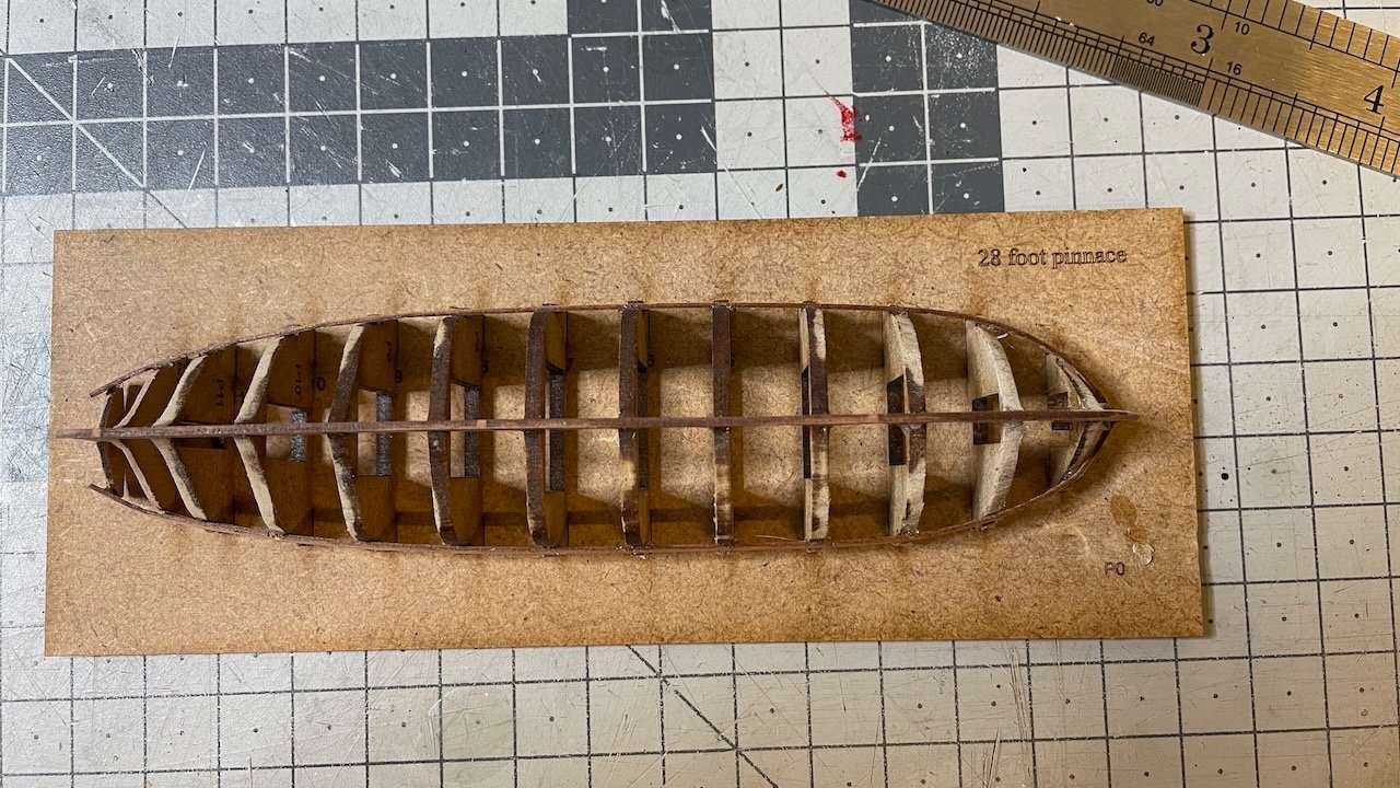
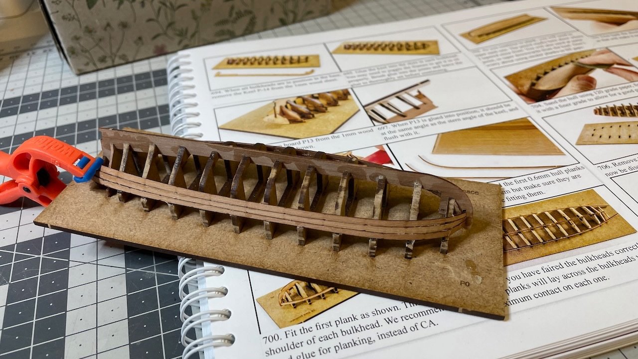
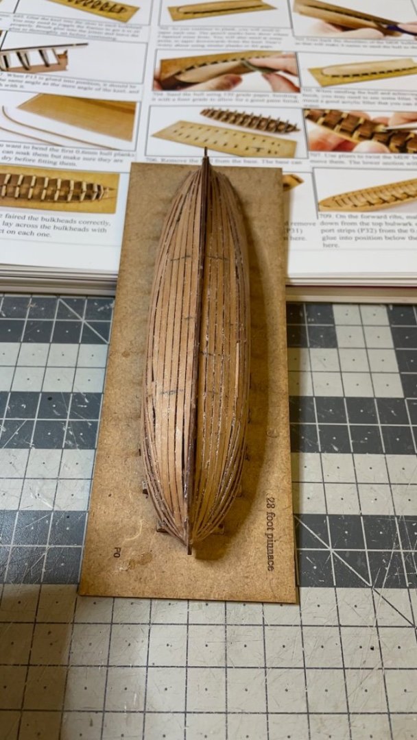
Photo 625: Planking went overall well. I think after the 4th row of planking from the top, I coninued from bottom (i.e. keel) up. At this stage I am relying on sanding and filling the gaps in order to get a smooth surface, which will be painted.
- BobG, Cirdan, KARAVOKIRIS and 2 others
-
5
-
1 hour ago, James H said:
Just remember to taper those planks as you fit them. Take a few of them and soak them, then add a gentle curl into them also. That will help get those first ones installed a little easier if you're not used to working on them.
Thanks for the advice James. I will certainly take my time with building these boats.
- Knocklouder and mtaylor
-
2
-
Photo 620: Coming up Next! Ship's boats. This is the most intimidating part of the build for me. I had tried to build the life boat once and failed in one of my earlier models. Ever since I always chose the easier option and went with the ready plastic hulls. This time I want to give them a try. Let's see how well I will achieve.
That's all for today. Thanks for watching!- etubino, mtaylor, Prowler901 and 3 others
-
6
-
Build Day 72: 1,5 hours / Total 164 hours
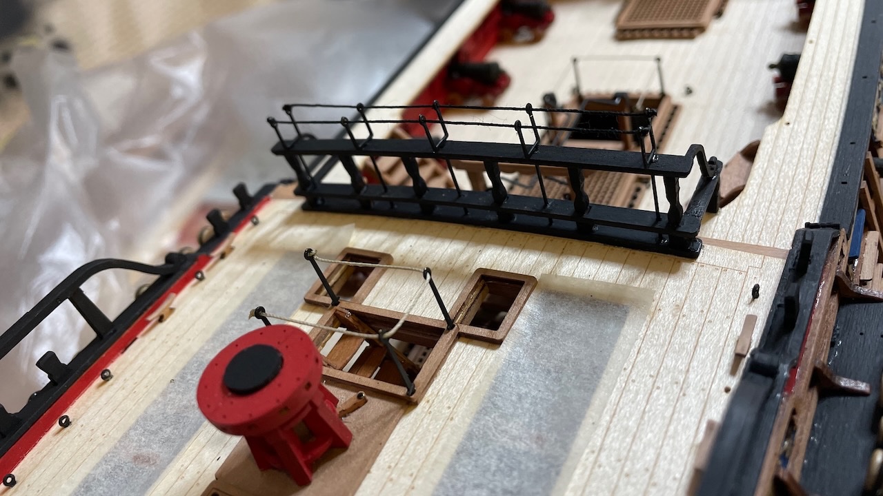
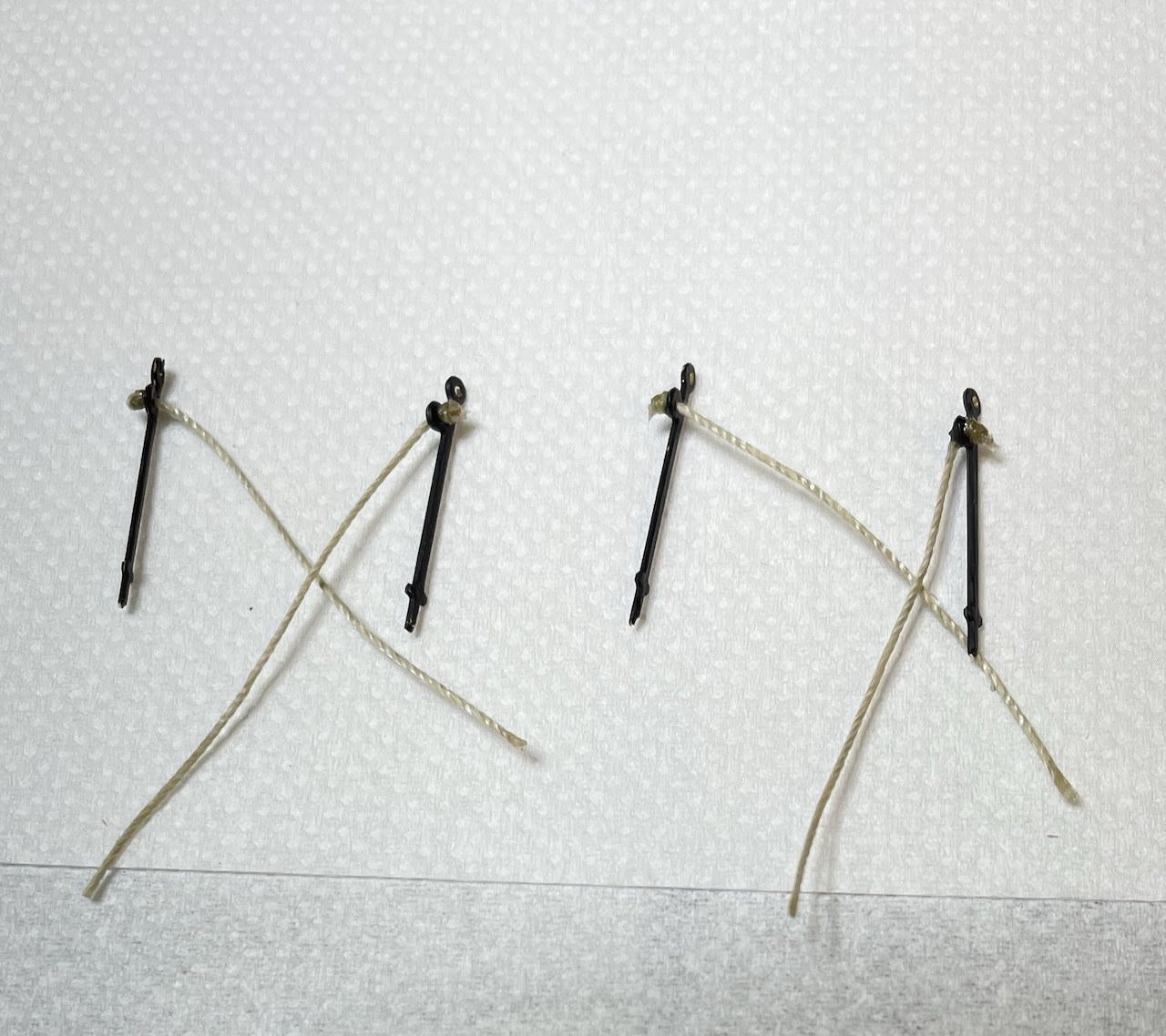
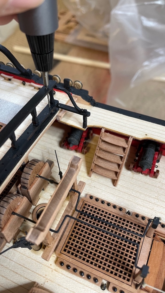
Photo 615: Waist Hammock Cranes and Waist Stanchions. Like before, I needed to use a 0,5 mm drillbit to open up the holes where the thread will go through. I still use a drop of CA glue to stiffen the end of the thread to help insert easily. Needless to say, I will retouch later the paint peeled of from the parts during process.
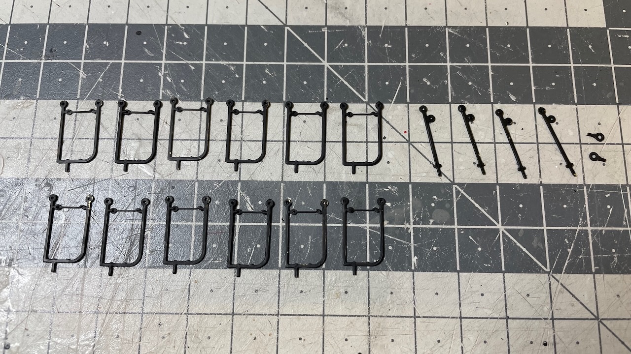
Photo 616: Though not seen in the manual photos, according to the plans the Waist Stanchions are to be rigged with a 35mm long natural thread. I guess you grab them to help climb the ladders to the deck.
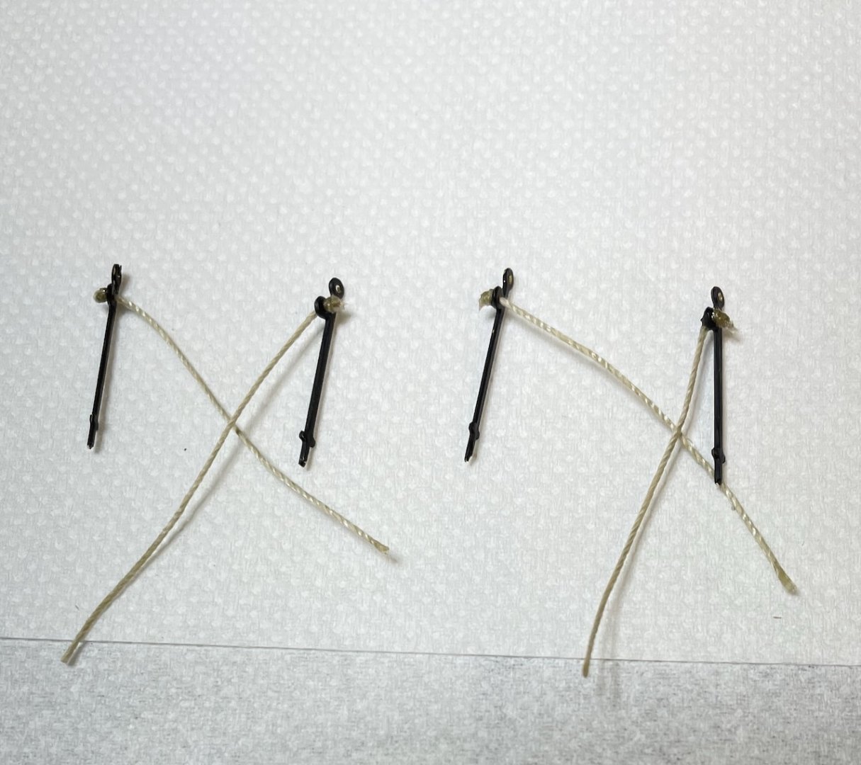
Photo 617: Glued and rigged. I also opened the holes using 0.8 mm drillbit to fit the parts. By the way it is a good approach to treat these holes mainly as a reference where to drill than assuming as ready to fit holes, since all the paint, varnish and glues usually clog them up during construction.
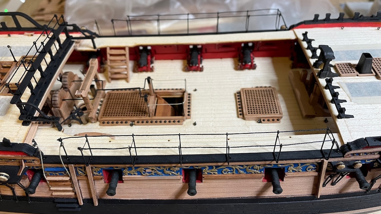
Photo 618: Forecastle Stanchions and drill dusts.
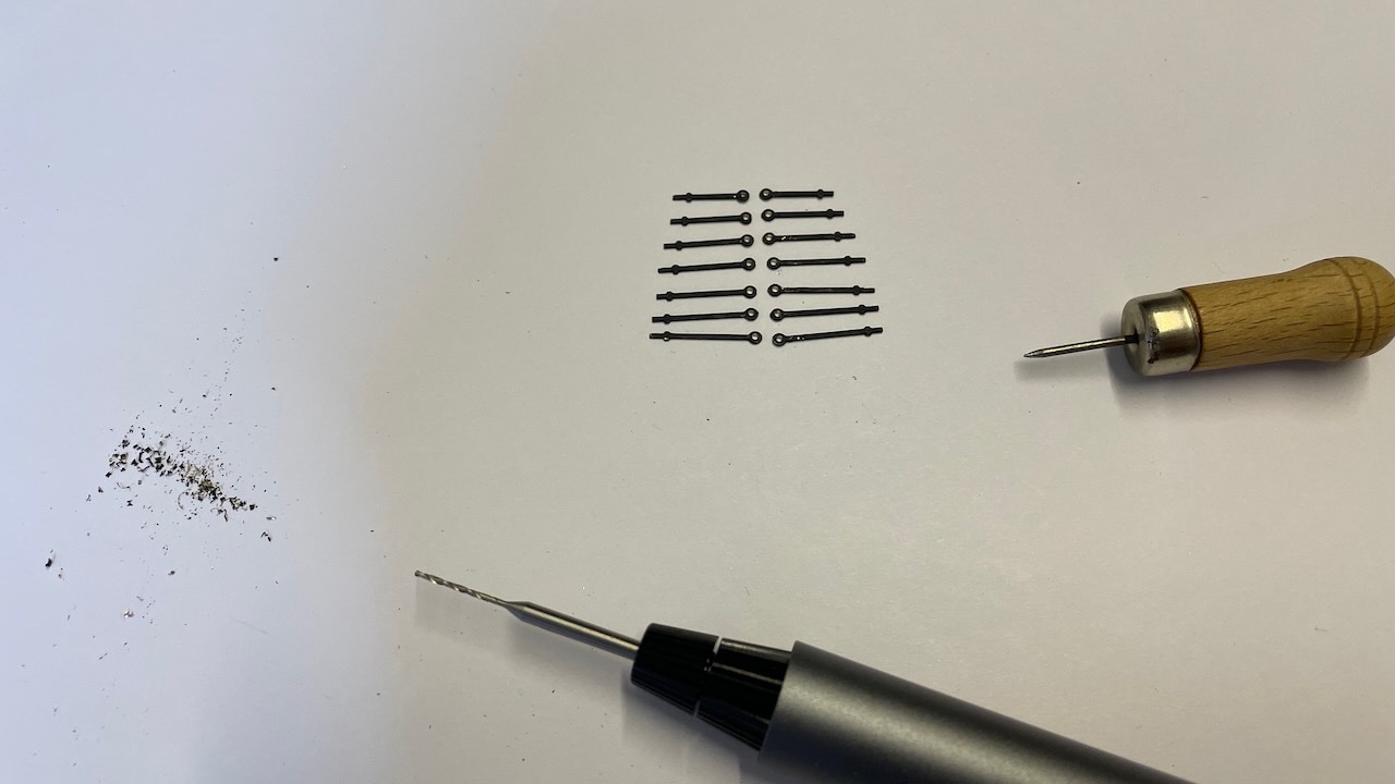
Photo 619: Glued and rigged.
- KARAVOKIRIS, Glenn-UK, BobG and 3 others
-
6
-
Build Day 71: 1 hours / Total 162.5 hours
Today Ladderway Stanchions and Quarterdeck Breast Rail Hammock Cranes.
Photo 611. Ladderway stanchions. Quite straightforward.
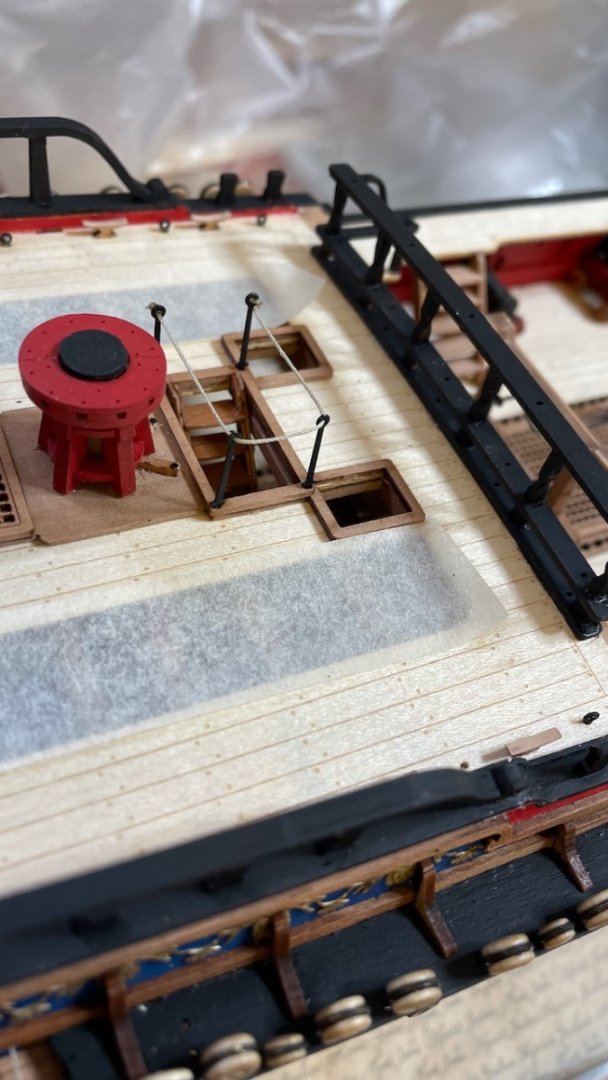
Photo 612. Painted (while on sheet) and removed the Quarterdeck Breast Rail Hammock Cranes. They look like Poseidon's spear to me
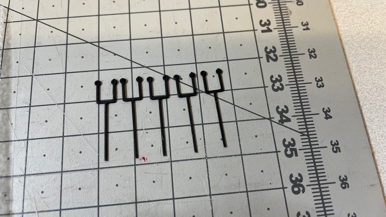
Photo 613. I needed to open up the holes a little, mostly due to clogging by paint. Luckily I happen to have a suitable drillbit with a long business end, that will drill straight through both holes st the same time.

Photo 614. All in place and rigged.
That's all for today. Thanks for watching!


HMS Sphinx 1775 by aydingocer - Vanguard Models - 1:64 - Revision #2
in - Kit build logs for subjects built from 1751 - 1800
Posted
Thanks for very useful tips. I have actually managed this section now but I will definitely refer to these tips in the coming steps. There are still several similar tasks ahead with the masts.