aydingocer
-
Posts
856 -
Joined
-
Last visited
Content Type
Profiles
Forums
Gallery
Events
Posts posted by aydingocer
-
-
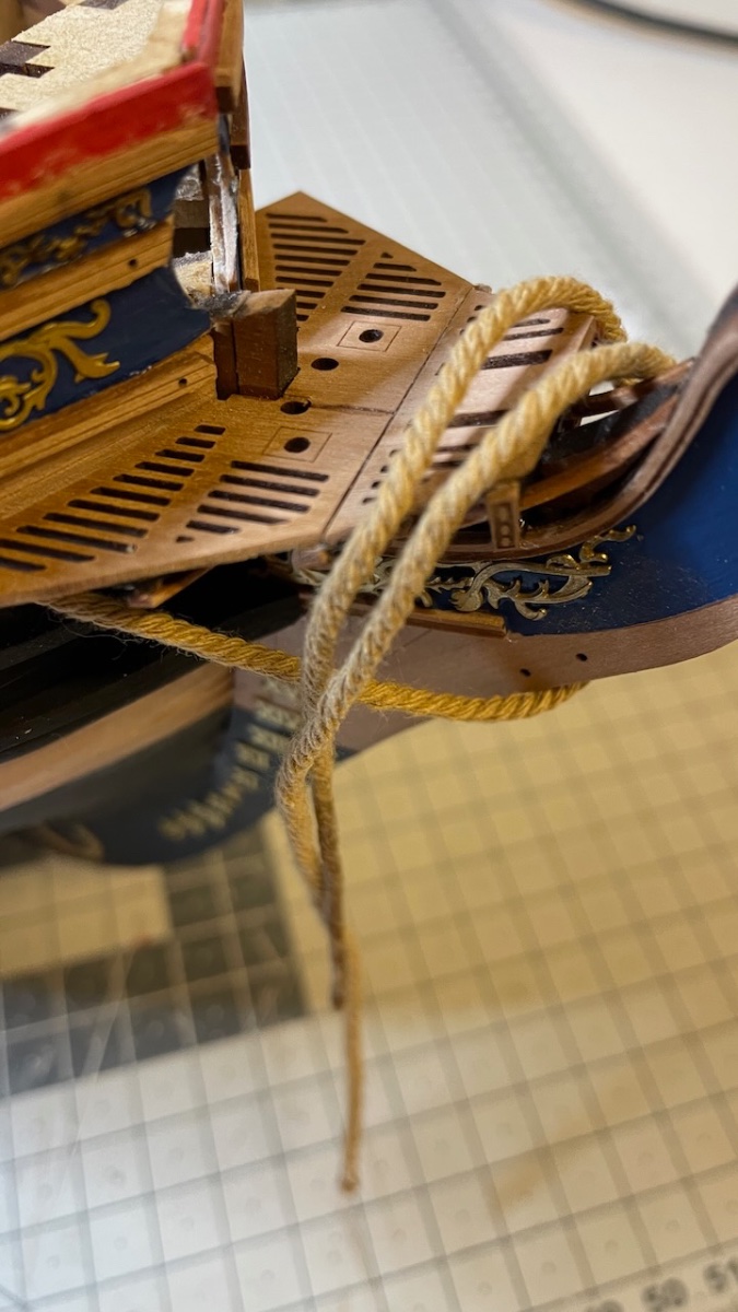
Photos 584-587: Anchor cable (i.e. the thick rope) installation. Hardened a few centimeters with CA glue on one edge help insert through holes easily. They should terminate with a knot behind the bulkhead but I may keep it in one piece just like in the photo. It won't be visible below the deck at all and it may help make adjustments while installing the anchors.


-
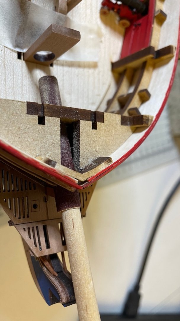
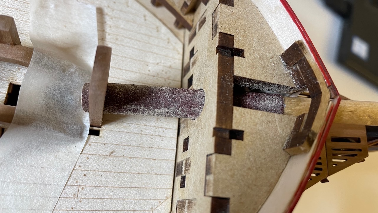
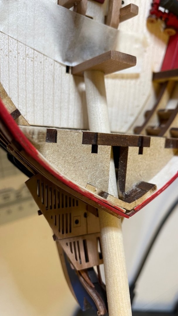
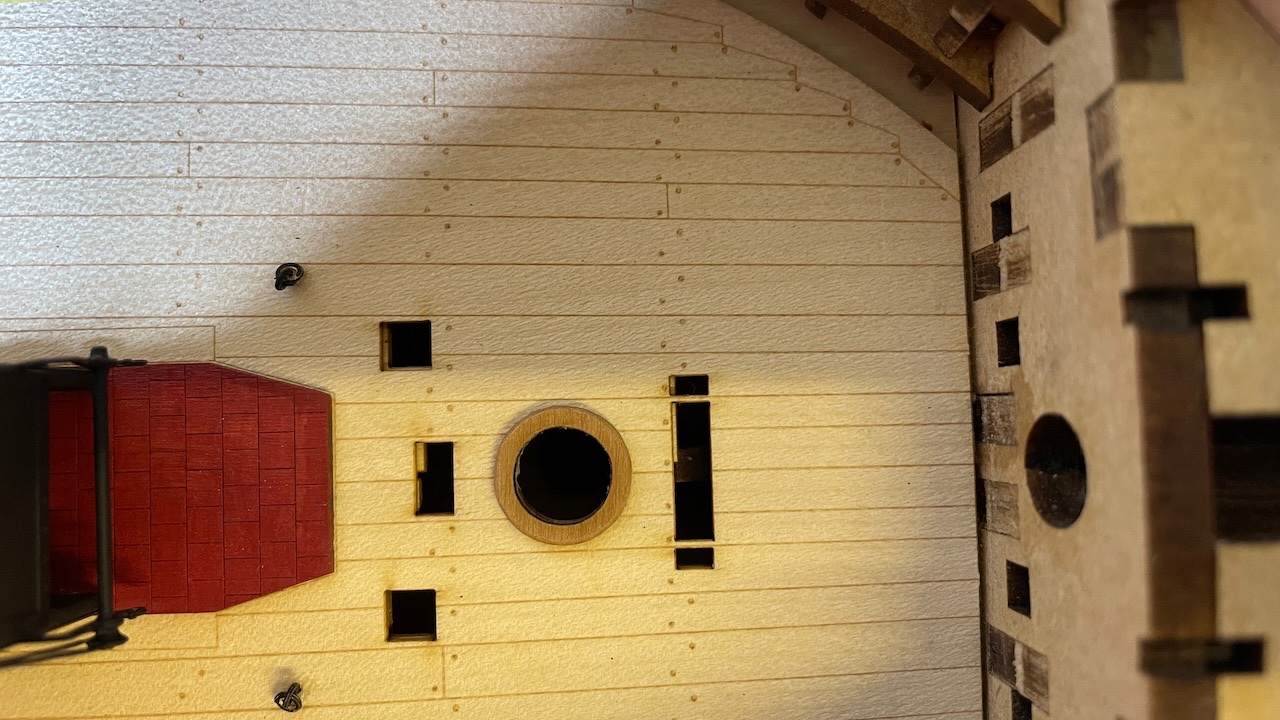
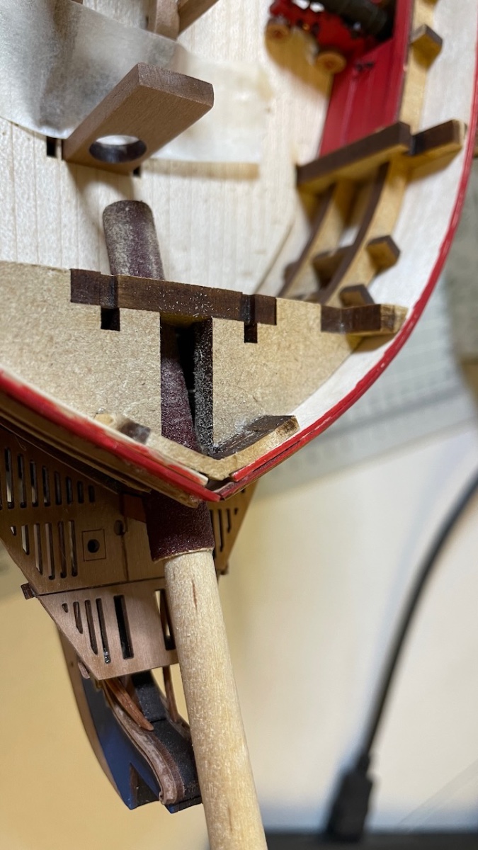
Photo 581-583: Bowsprit opening. I wrapped and glued a thick sandpaper (actually those you use on electric band sanders) around a 6mm dowel and sanded the opening as instructed, including the Bowsprit support on the deck, until my 8mm dowel fits nicely (3rd photo below. Note it is just another 8mm dowel from my stock, not the Sphinx bowel).
- bruce d, Mr Whippy, Oldsalt1950 and 3 others
-
 6
6
-
-
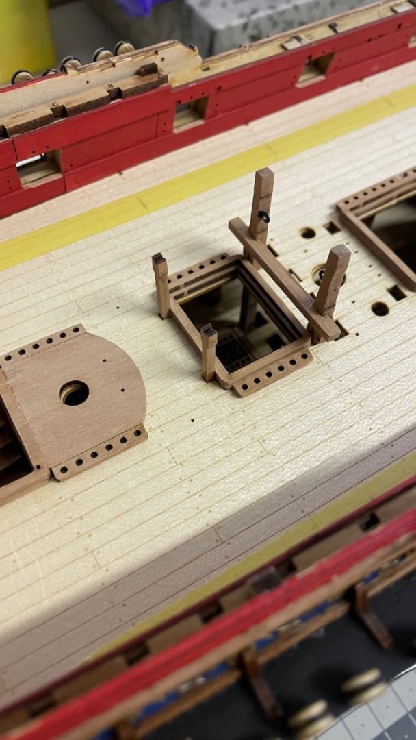
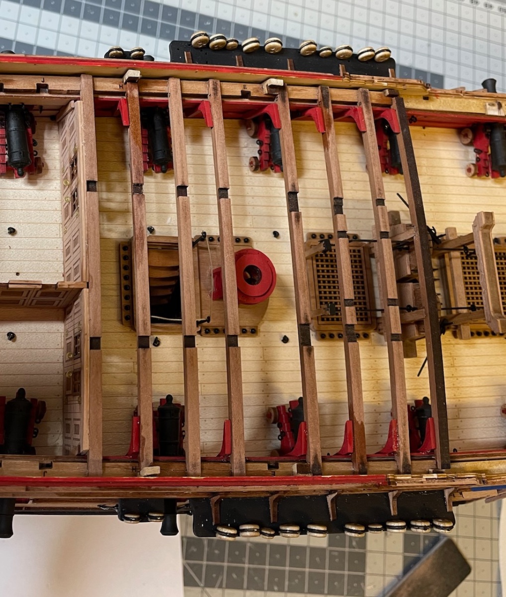
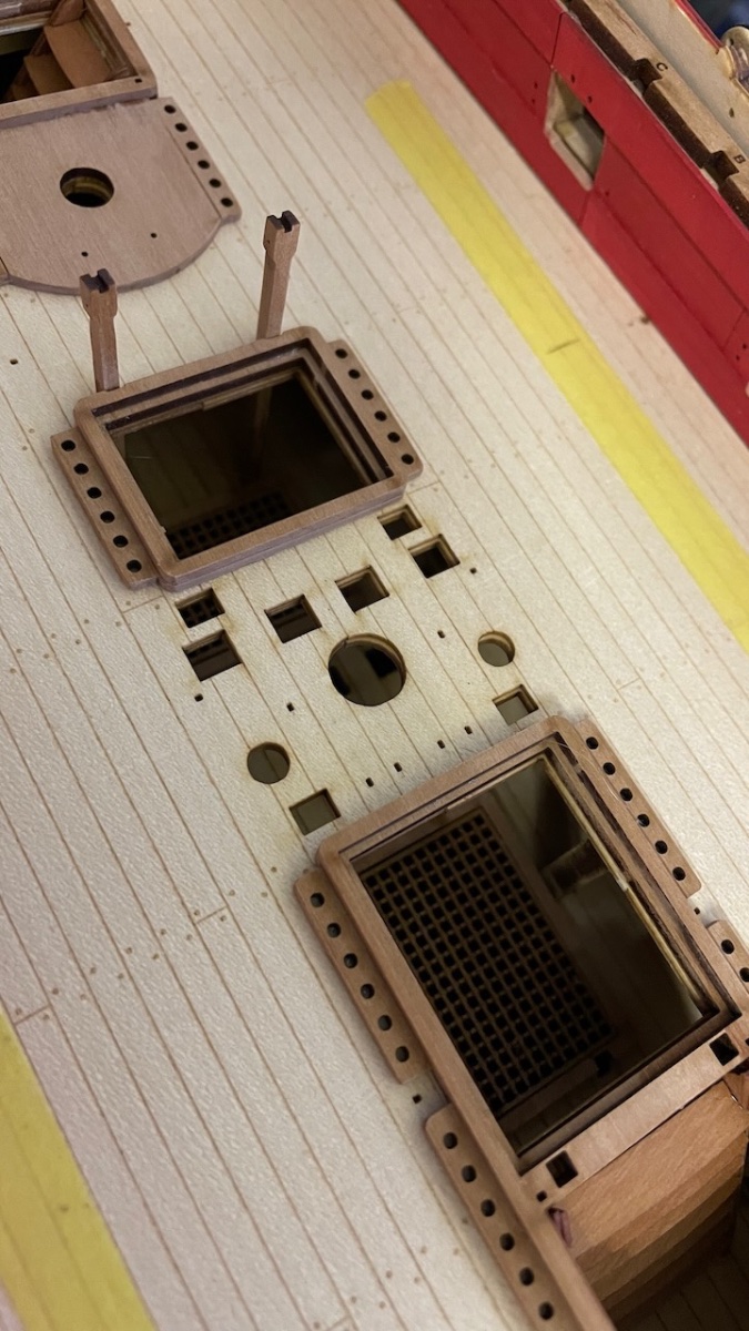
Build Day 57: 4 hrs / Total 133,5 hours
Deck beams. Overall they went without any problems, just minimal sanding and corrections here and there. The way they are designed and is excellent, as in general with this kit.
Photo 571: Below the Quarterdeck ones removed and cleaned:
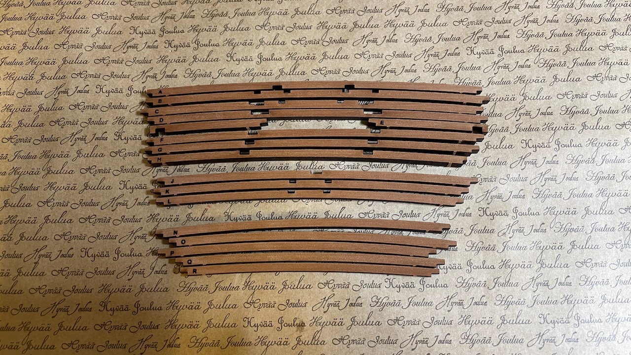
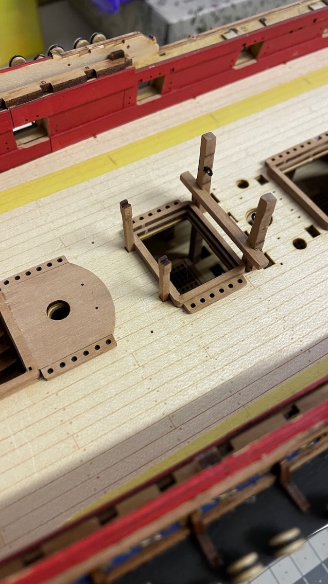
Photo 572: First one to glue sits on top of chain pump handle stanchions, hence it is important to make sure the stanchions have the correct height. I noticed after installing this beam when comparing with the other beams that mine were about 1mm too high, making this one too high to fit the deck sheet later, and I sanded off the beam until the height and curve is flush with rest of the beams.
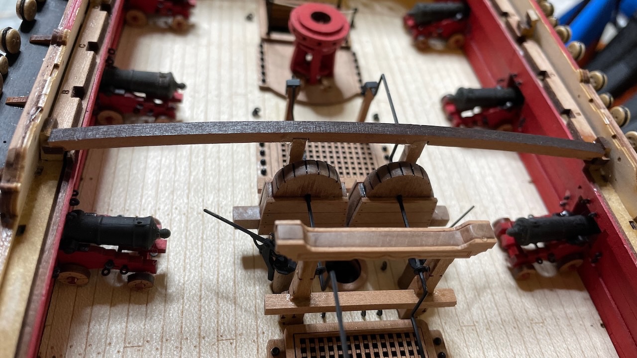
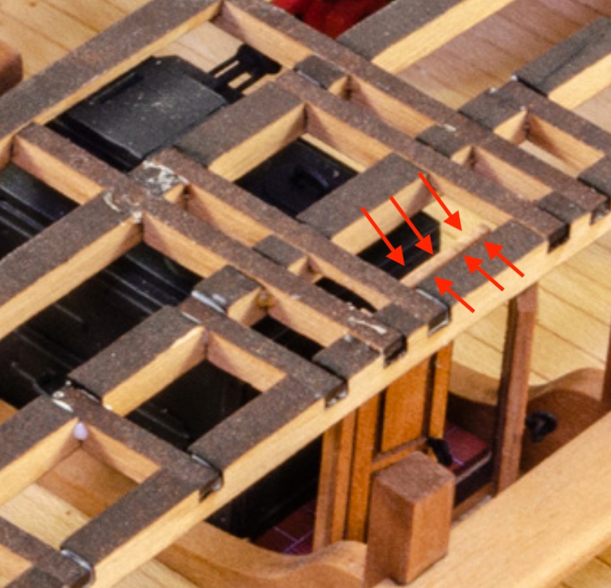
Photo 573: As stated in the instructions, the beams should follow a layout about parallel to the gun deck. It means they should have a slight downward slope towards aft. Without it, the last one won't sit on the bulwark shoulders, as seen in this dry fit photo: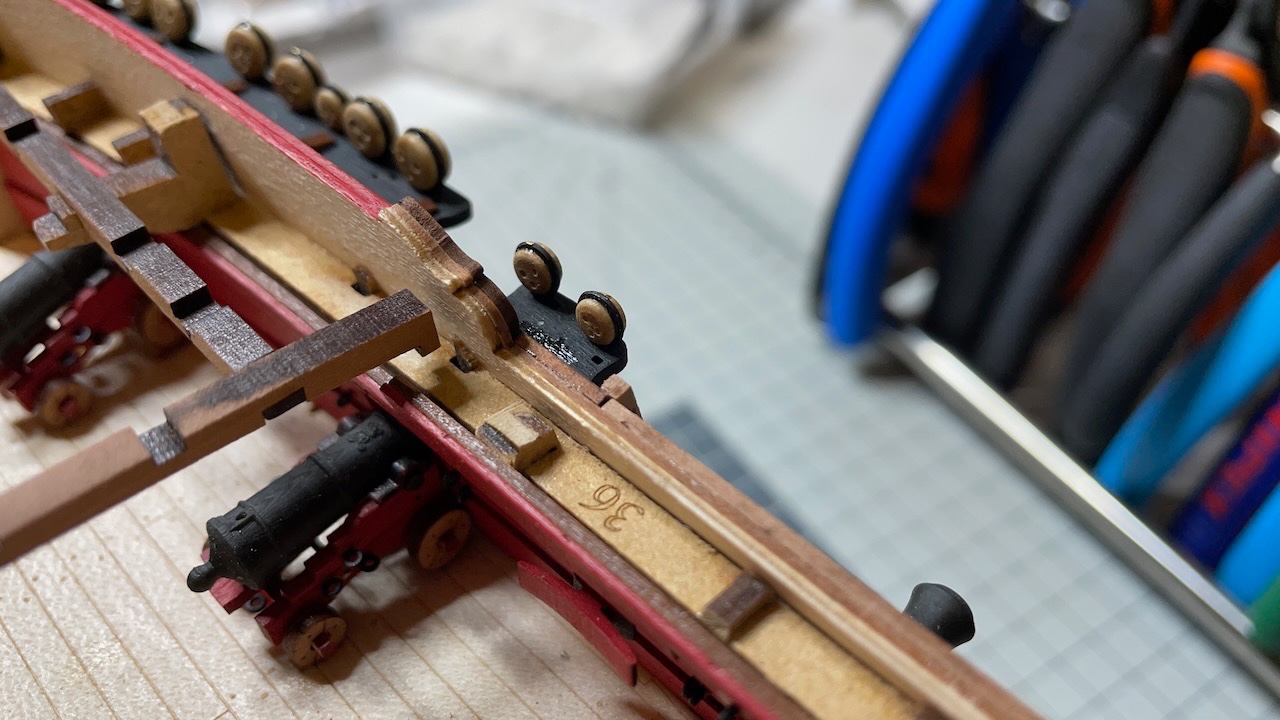
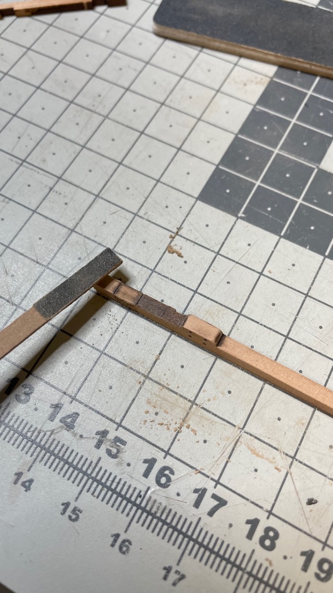
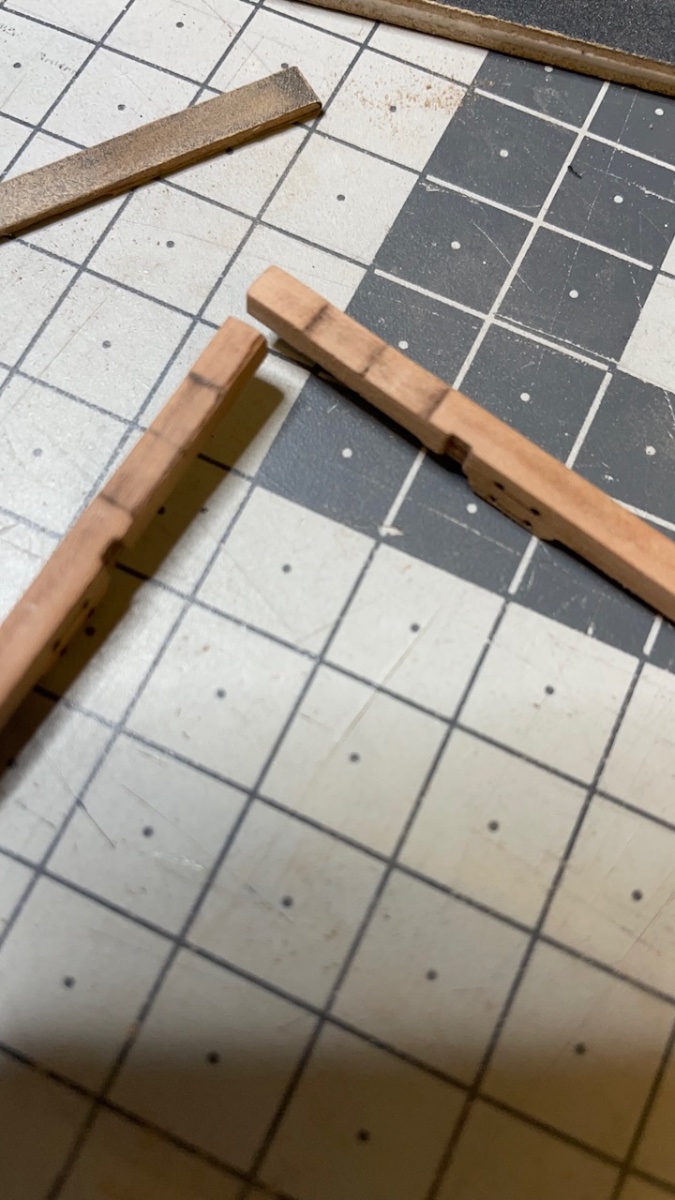
Photo 574: I sanded bulkhead beam slots on both sides as in the picture, in order to give the necessary slope.
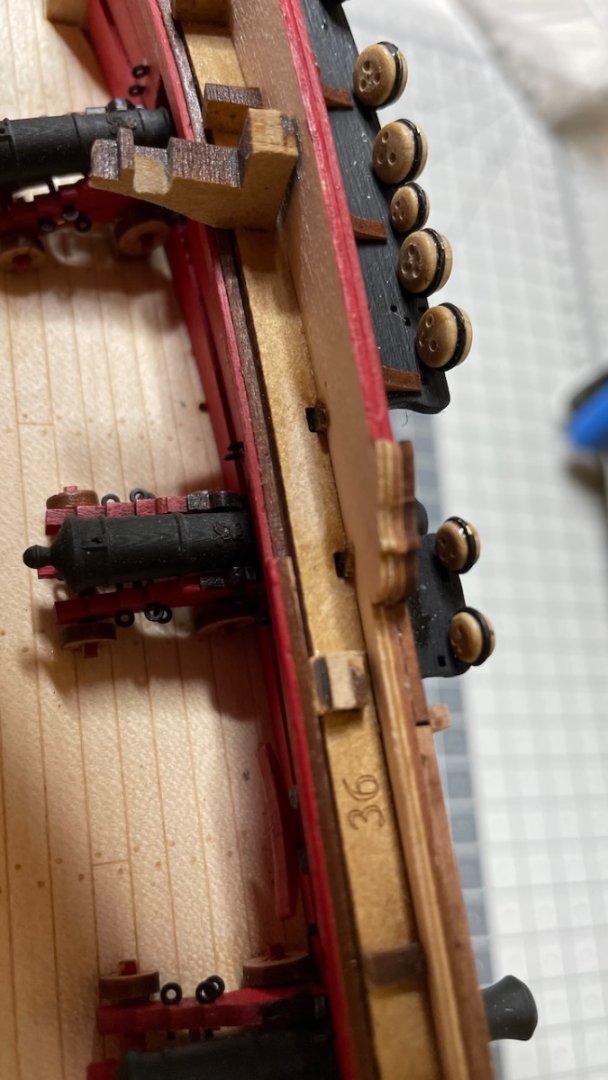
Photo 575: Now they sit properly.
-
Build Day 56: 3 hrs / Total 129,5 hours
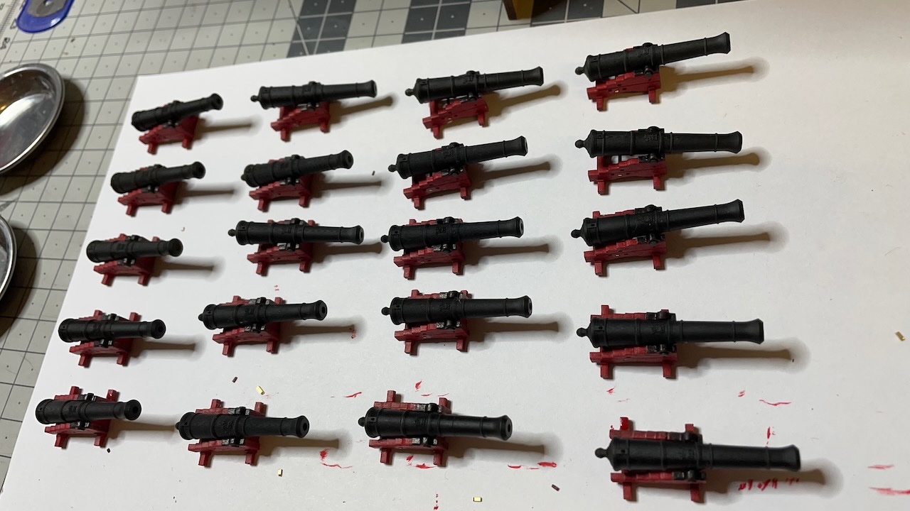
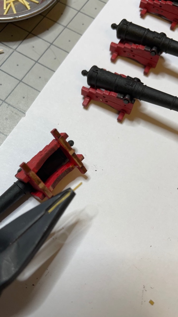
3 hours of work covering the completion of cannon carriages, including gun port painting, which I noticed I forgot to do, almost too late.
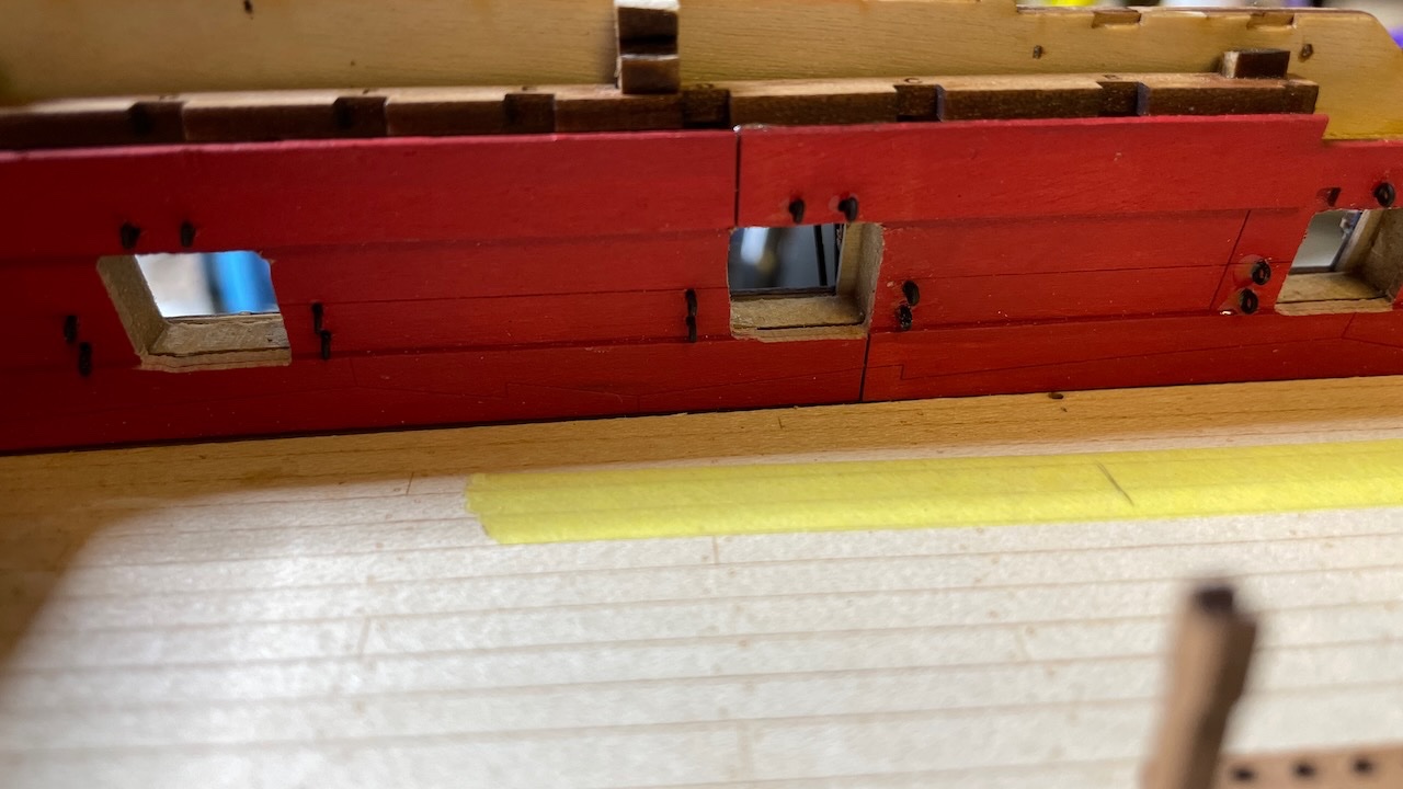
Photo 569: Gun ports painted in red. I should have done it earlier and it was a bit tricky to reach some parts with brush after all the other details around, but I survived.
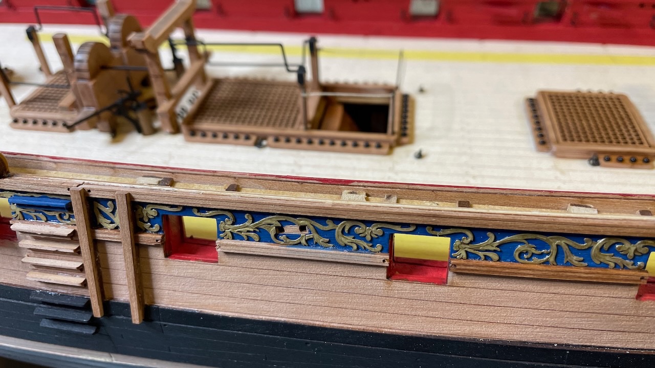
Photo 570: All cannons in place. I decided not to rig them at all. They will be barely visible in the end.
-
-
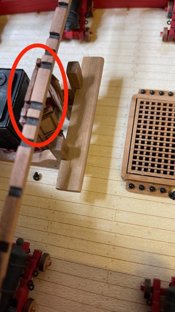
I have proceeded without having time to post my diary, but anyway, I have a question about the deck beam "Z" . In my model it fits right beside the door frame aligning with its grooves. In the manual it somehow looks like it goes over the door. Has it changed since the prototype or am I making a mistake? @James H can you comment? I haven't glued "Z" yet, it is dry fit in the photo.
Photos 567-568 : The picture in the manual vs my build:
-
15 hours ago, James H said:
The ink brush pen is a nice idea!
Got the hint from a childhood neighbour friend of mine, after seeing the excellent cockpit detail paintings of his helicopter model and asked him how he managed that.
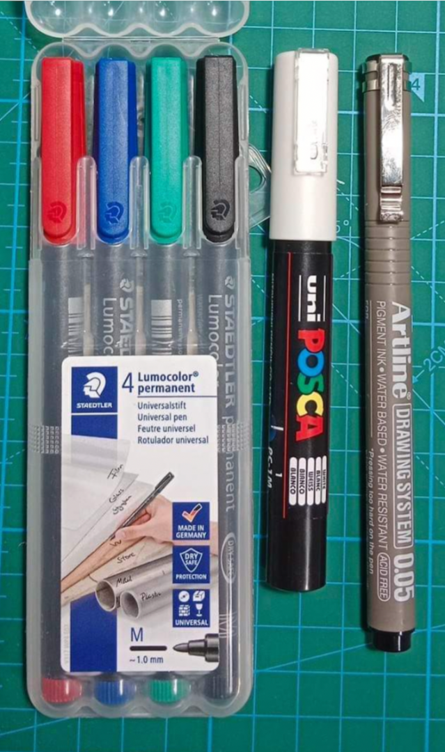
Also see Staedtler M size for color finishings and UniPosca 0.7mm for white: just touch the spot and that's it.
 .
.
-
-
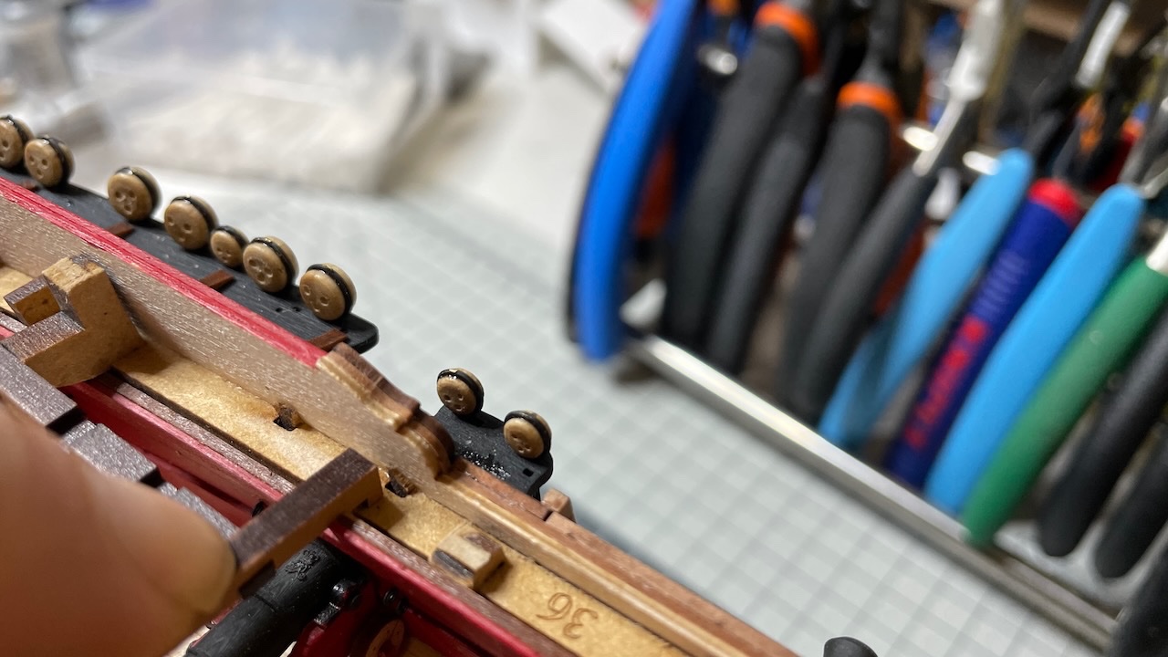
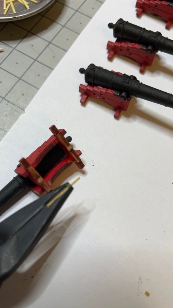
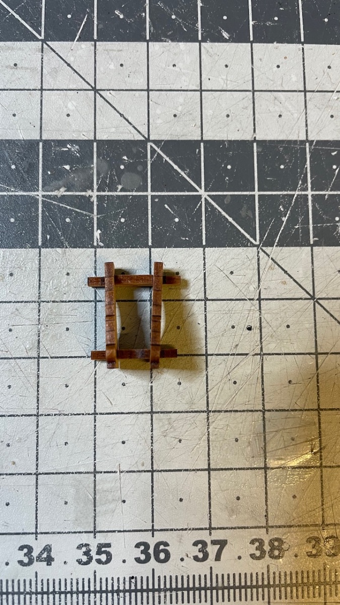
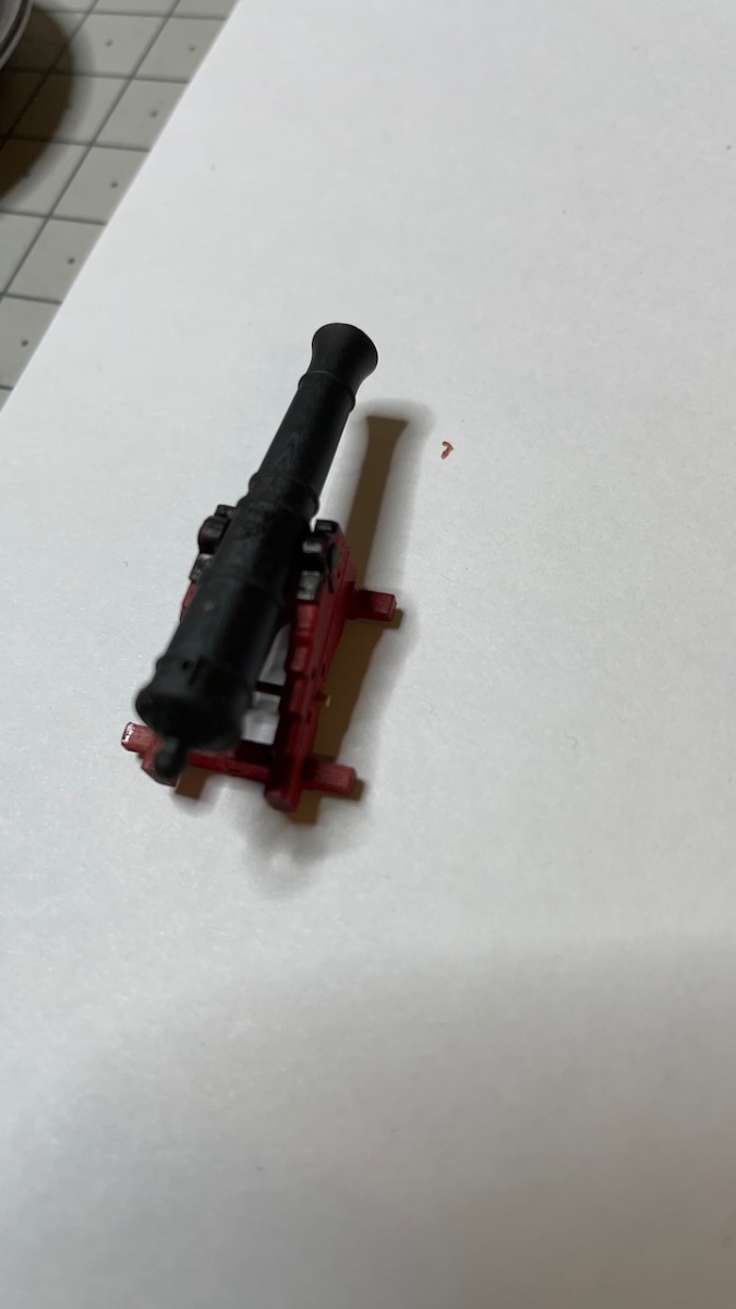
Photo 556: One of the carriage side piece will be glued after the gun has been inserted. However it is used now for correct alignment of the other 3 parts. Note the two sides are not parallel, they are a bit further apart at the back.

Photo 557: 3-piece constructions are ready.
Photos 558-562: Painting . Wheels will stay as they are. All parts are applied one layer of varnish before applying paint.
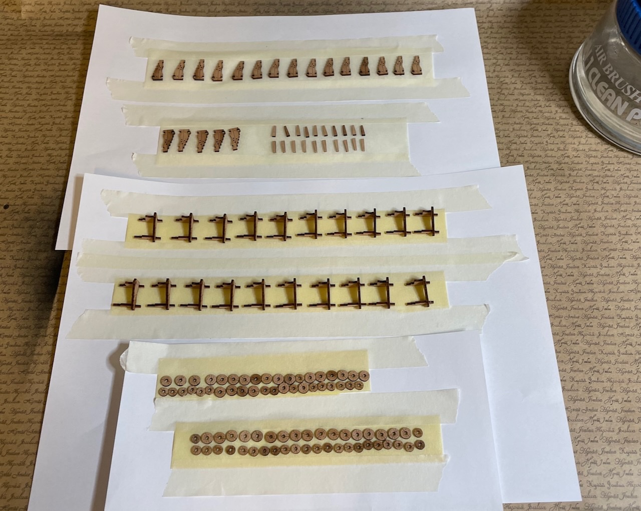
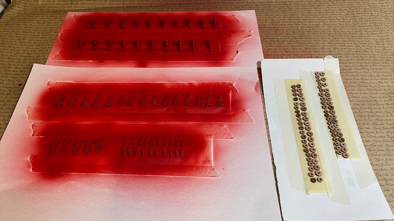
Photo 563: Tip: For painting the cap square details I use this pen with permanent black ink. Works better than any paint brush.
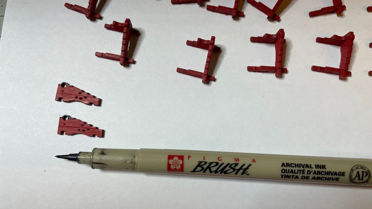
Photo 564: A detail showing the cannon carriage cross bar (going underneath the gun).

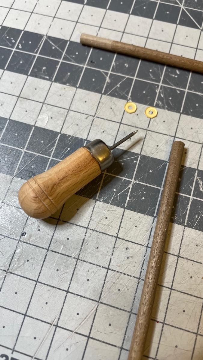
Photo 565: My pin pusher comes in handy here, too. It allows to push it in small increments, making it possible to get the cross bar across the two holes without bending.
- James H, Oldsalt1950, ct mike and 3 others
-
6
-
-
-
Build Day 54: 4 hrs / Total 125.5 hours
Photo 549: 4 Gun Deck Bulwark Cleats (430) are painted and glued in place.
Photos 550-551: Chain pump handle bars. I skipped inserting the nails across the brass pillar caps. Just glued them and painted in black.
- DonSangria and mtaylor
-
2
-
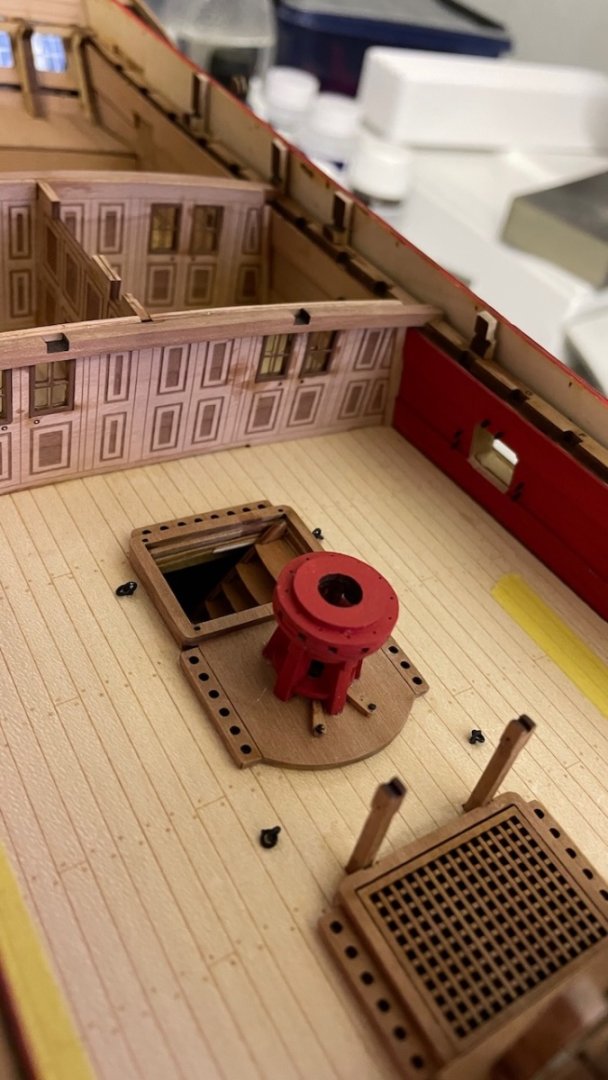
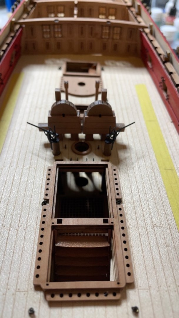
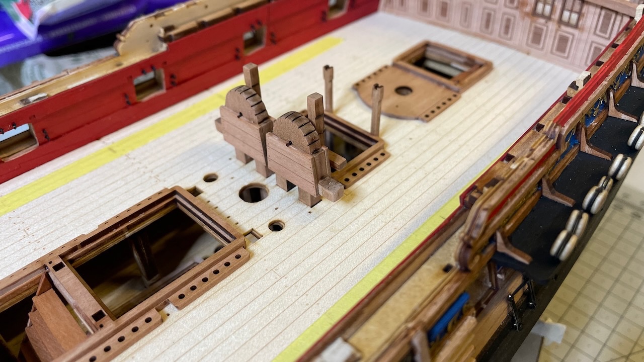
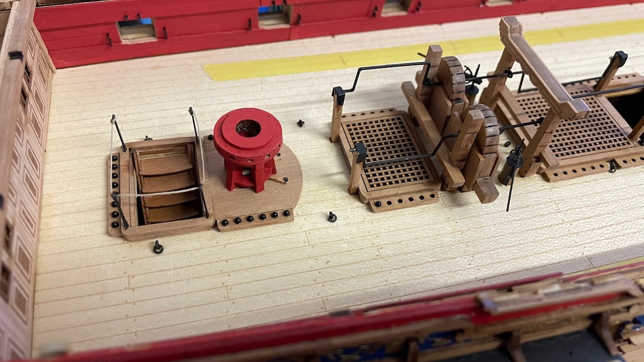
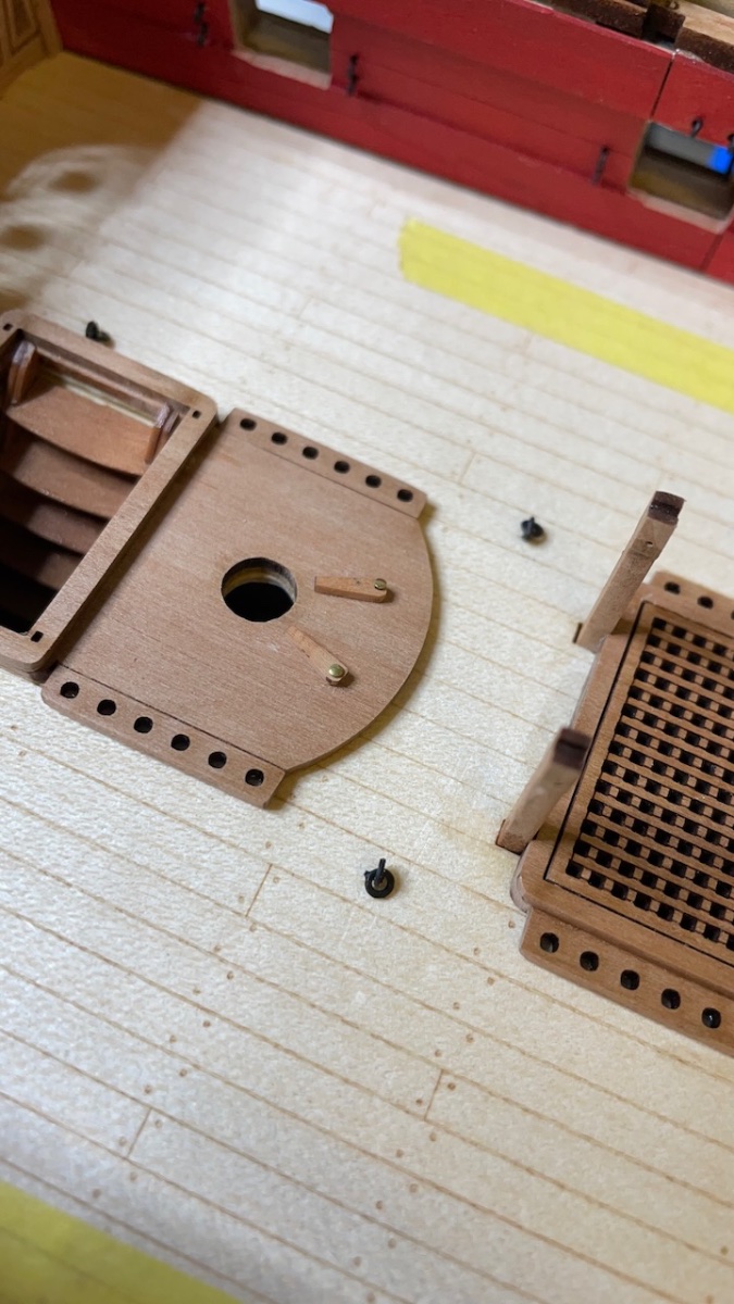
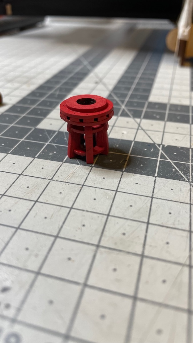
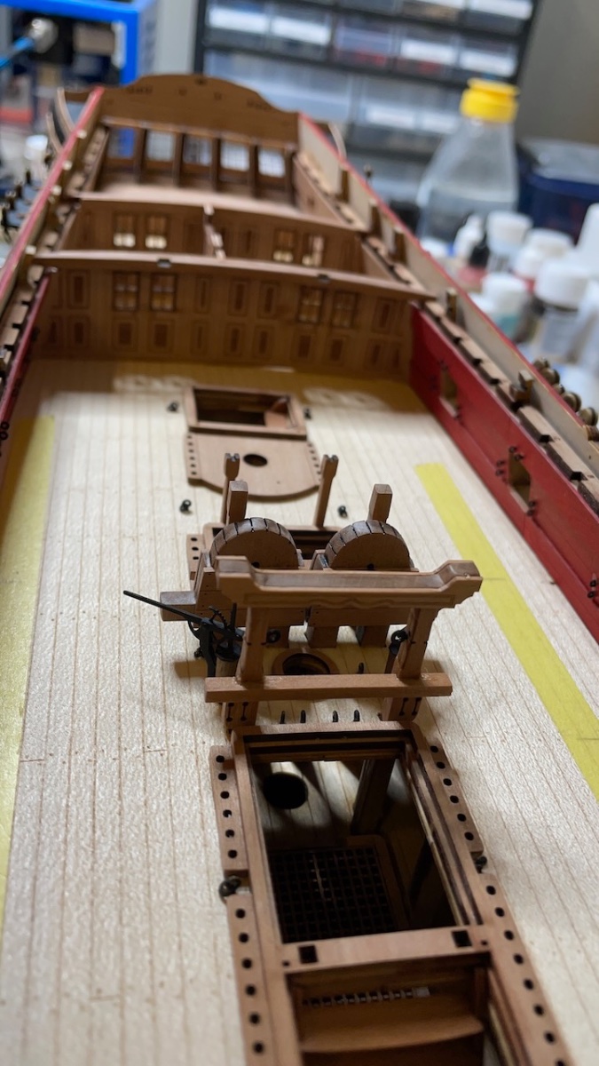
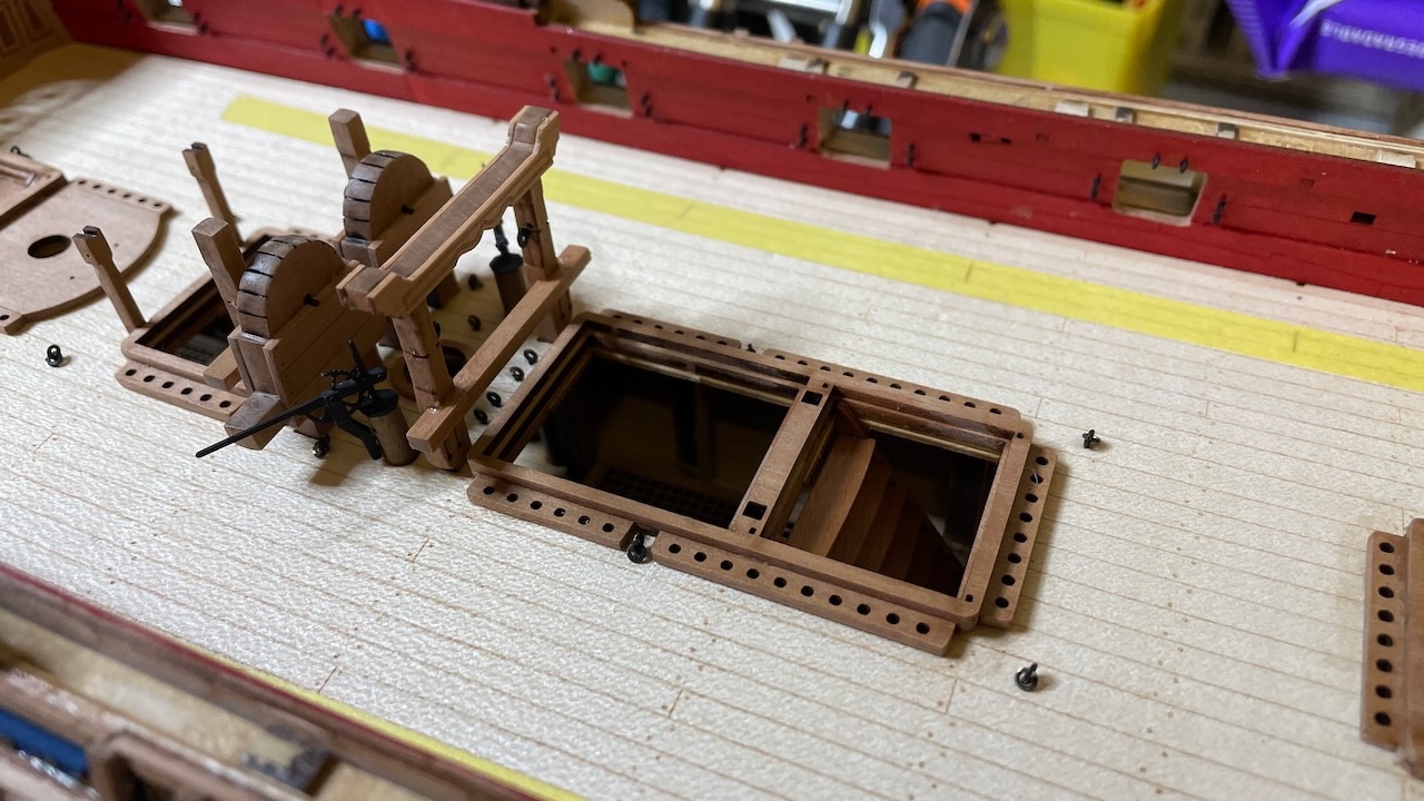
Photo 545: These two small parts in front of the capstan were omitted in the instructions but they are there in the next photos. It is good to be aware as it is easier to install them before gluing the capstan.

Photos 546-548: Capstan painted in same red and glued in place.

- DonSangria, Prowler901, hollowneck and 6 others
-
9
-
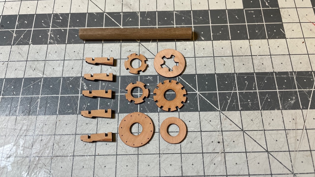
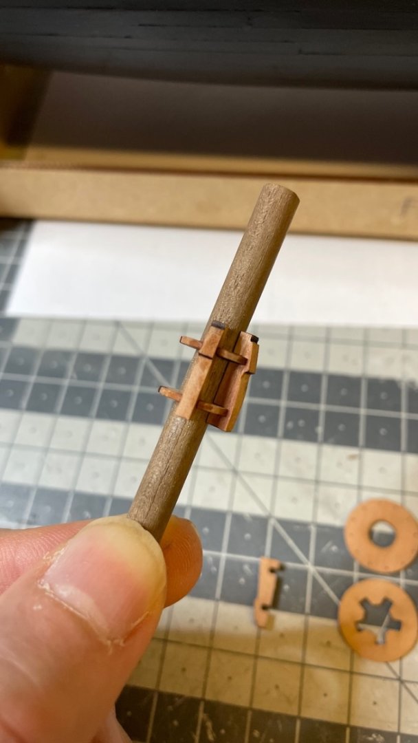
Photos 541 - 544: Lower capstan construction.


- Cirdan, Prowler901, ct mike and 1 other
-
4
-
Build Day 54: 2 hrs / Total 123.5 hours
During the deck work most of the time goes removing the laser char from the edges. Not so much fun, but has significant impact on the end result.
Photo 538: Fore mast base cleaned, rounded and glued in place.
Photos 539-540: Fore Ridings Bitts and Bowsprit support. Check from the plan to ensure that the bowsprit support height is correct. The Bowsprit will fit there later.
- Prowler901, Cirdan and JeffT
-
3
-
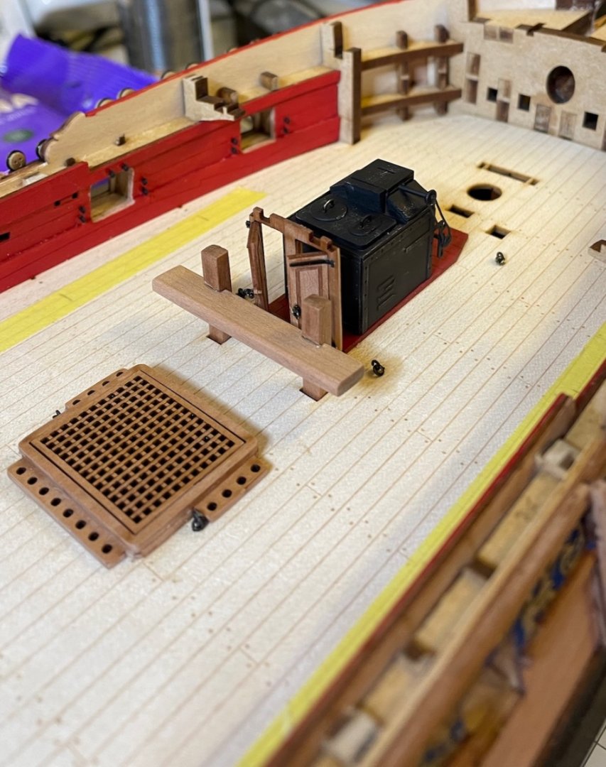
Build Day 53: 1.5 hrs / Total 121.5 hours
Photo 537: Riding Bitts and Gallery Doors right behind the stove.
- chris watton, JeffT, mtaylor and 2 others
-
5
-
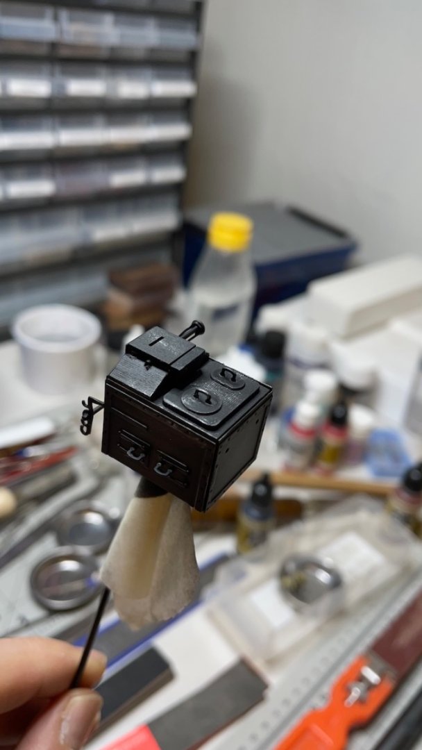
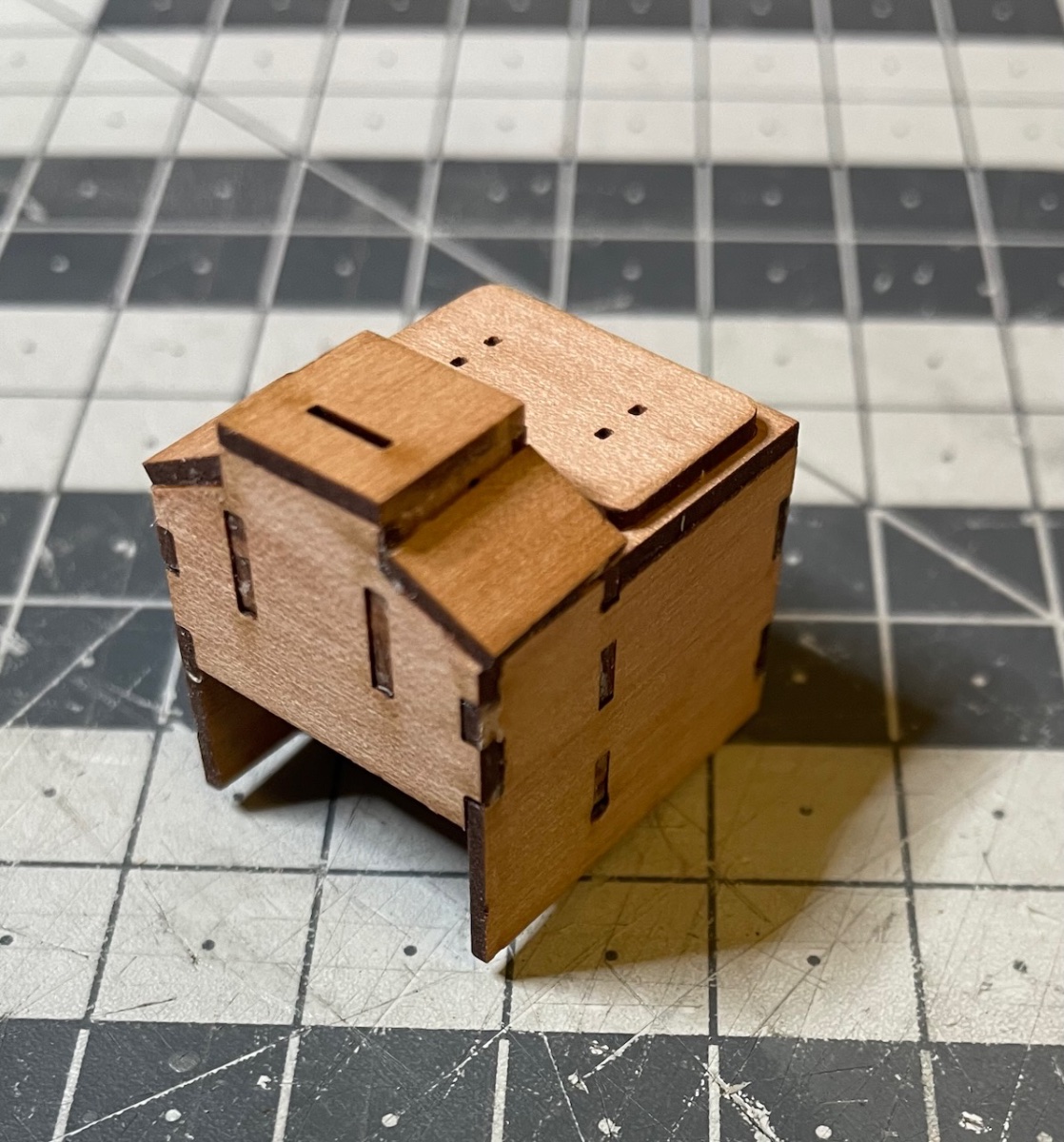
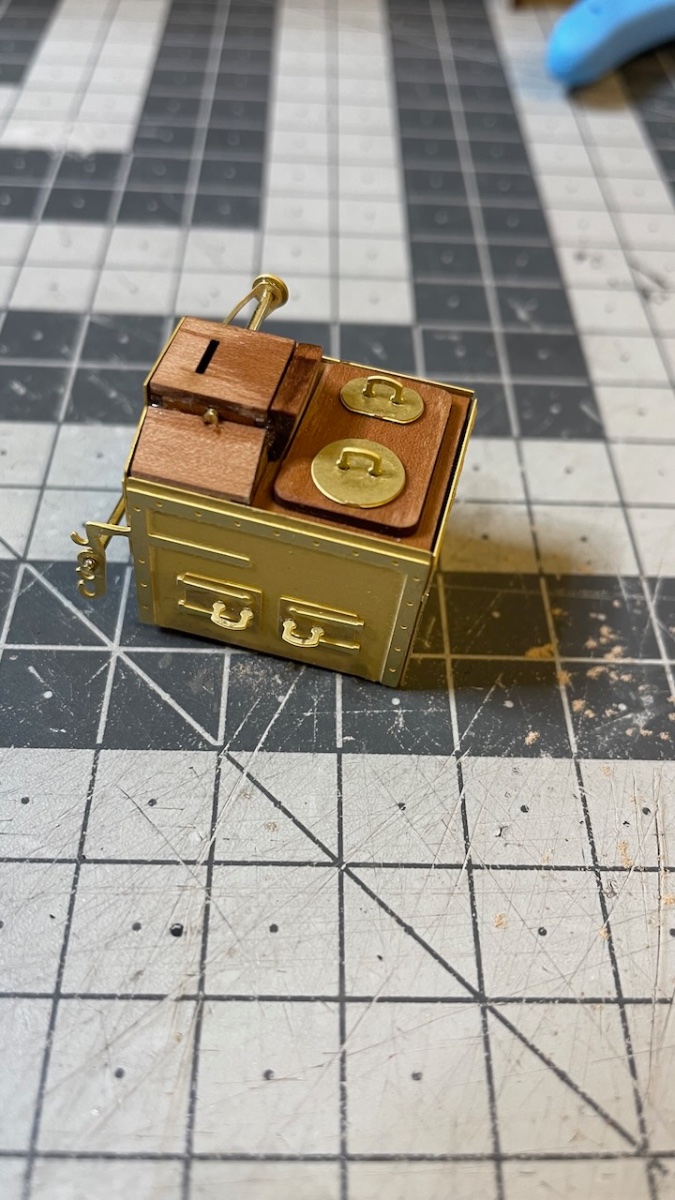
Build Day 52: 3 hrs / Total 120 hours
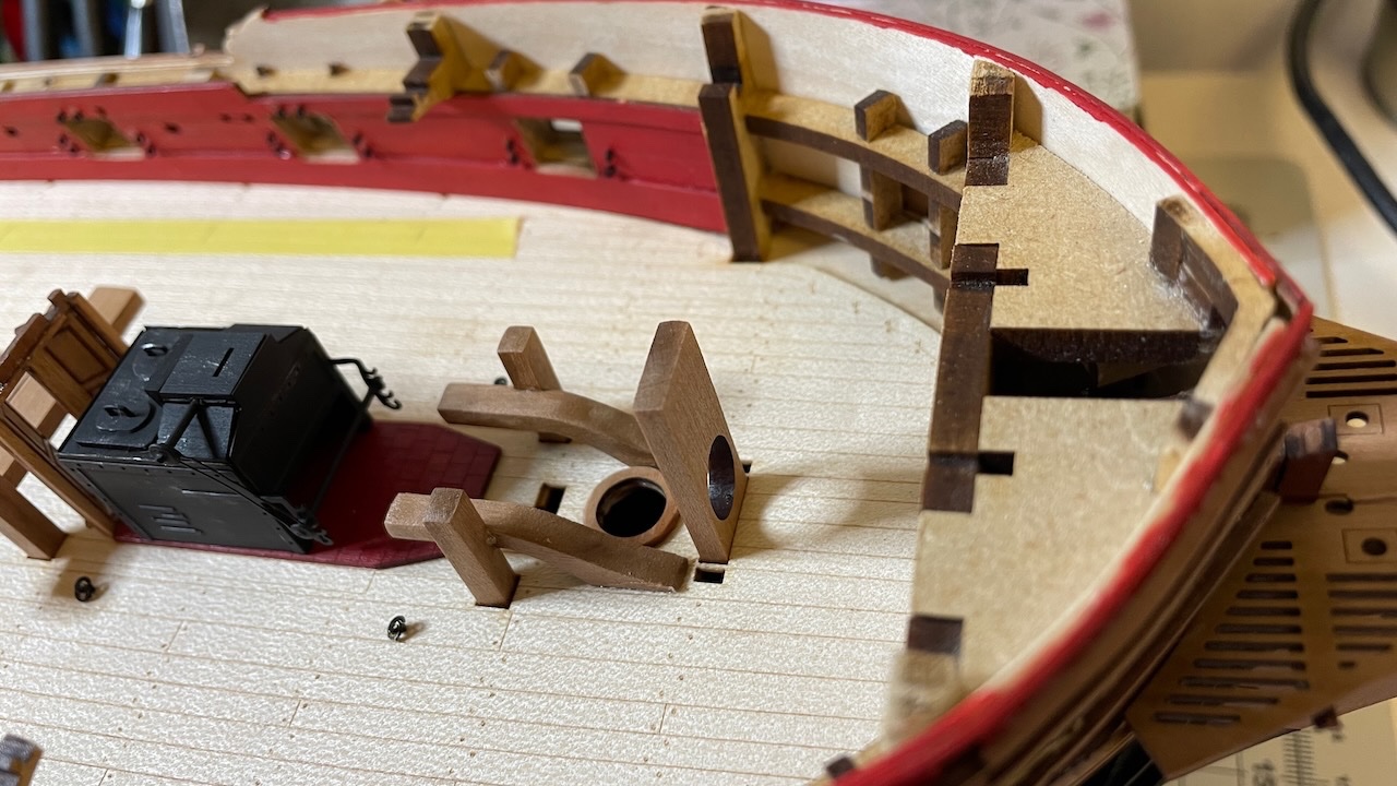
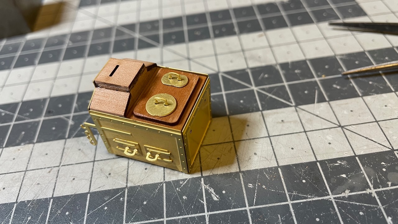
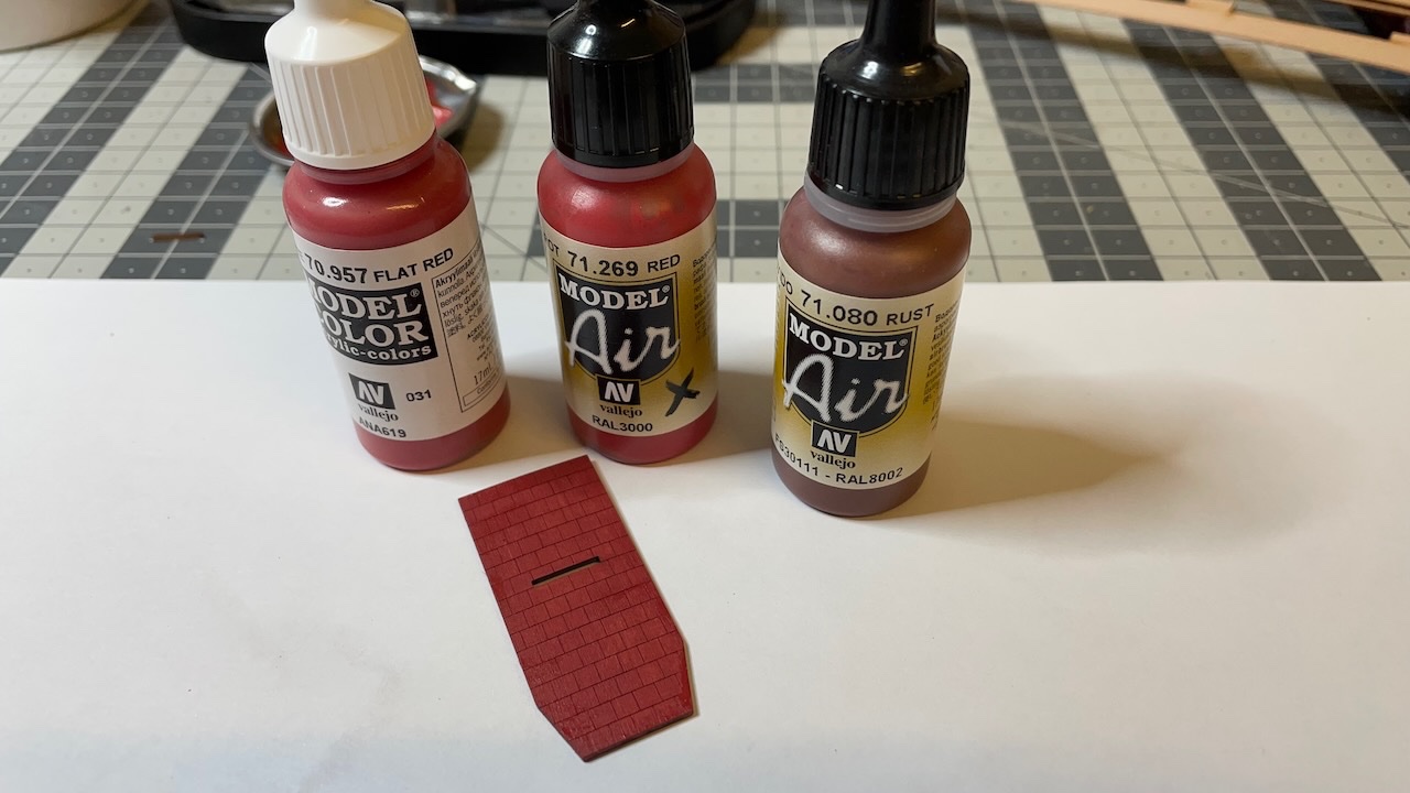
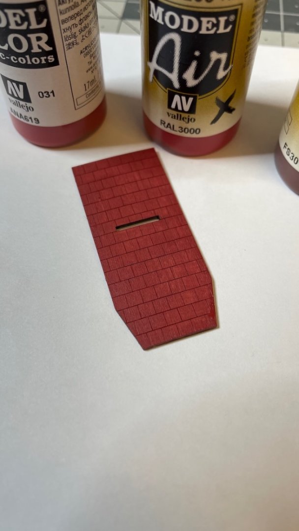
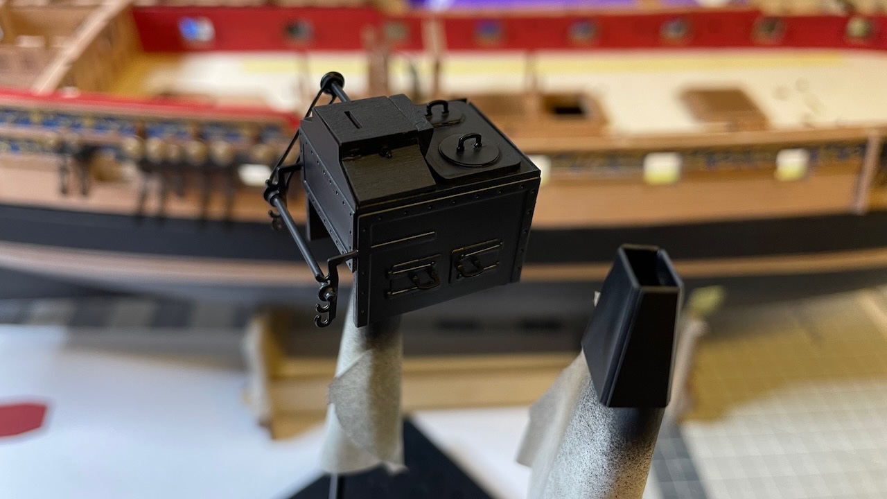
Below a sequence of photos showing the stove construction and installation.
I used a mixture of two red and one rust color in my paint stock to get the floor brick colour under the stove. The actual color looks a bit different than in the photo, and I am happy with the result.
For the stove, after painting matt black with airbrush, I gently applied steel color by barely touching with an almost dry brush. This gave the stove the metal and used look I wanted.
Photos 528-536


-
-
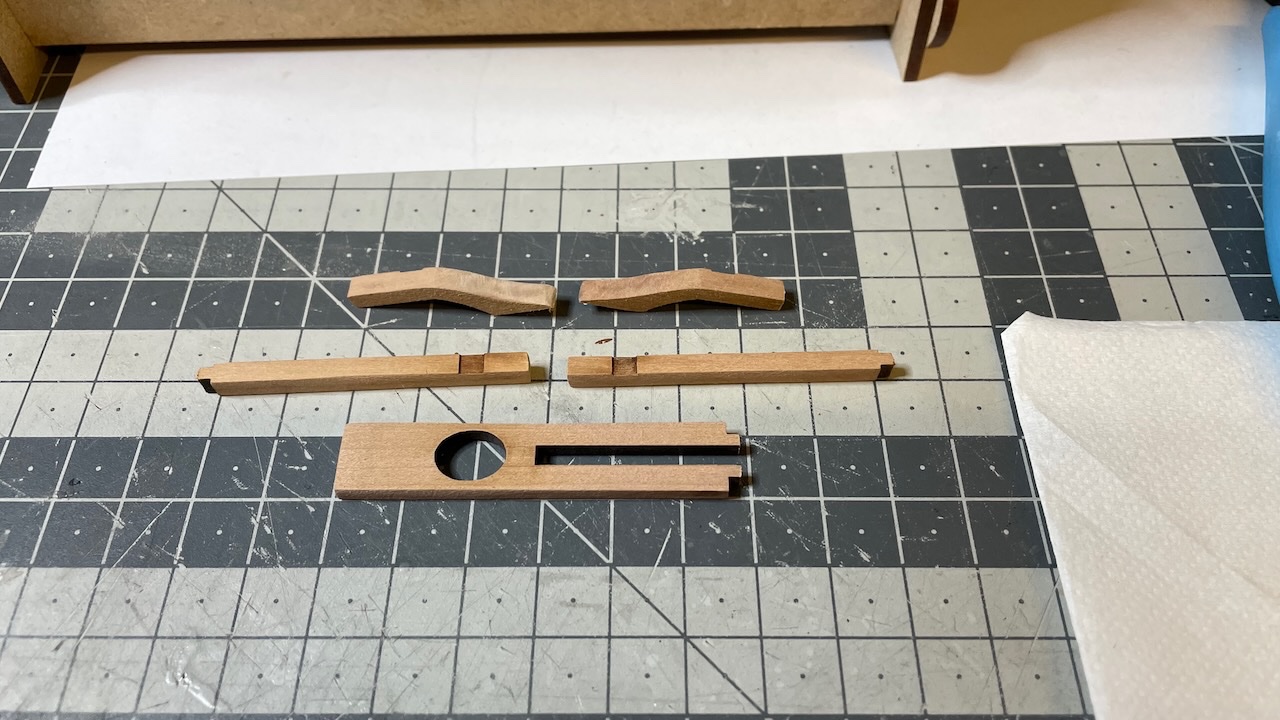
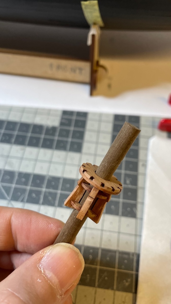
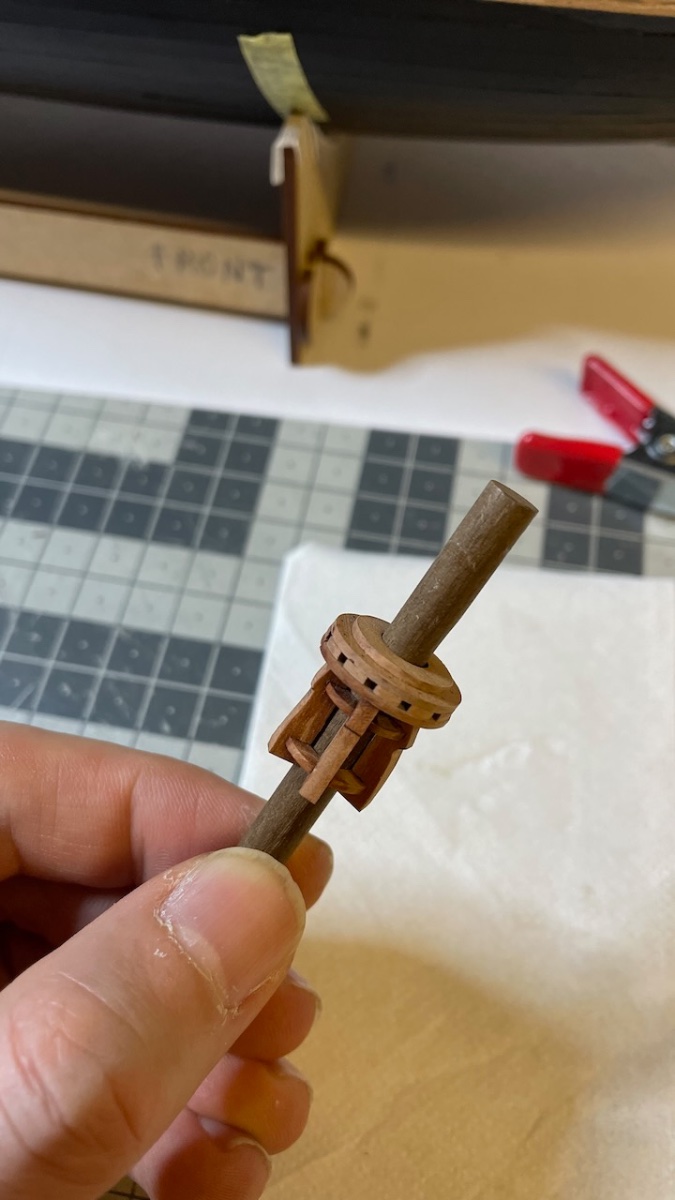
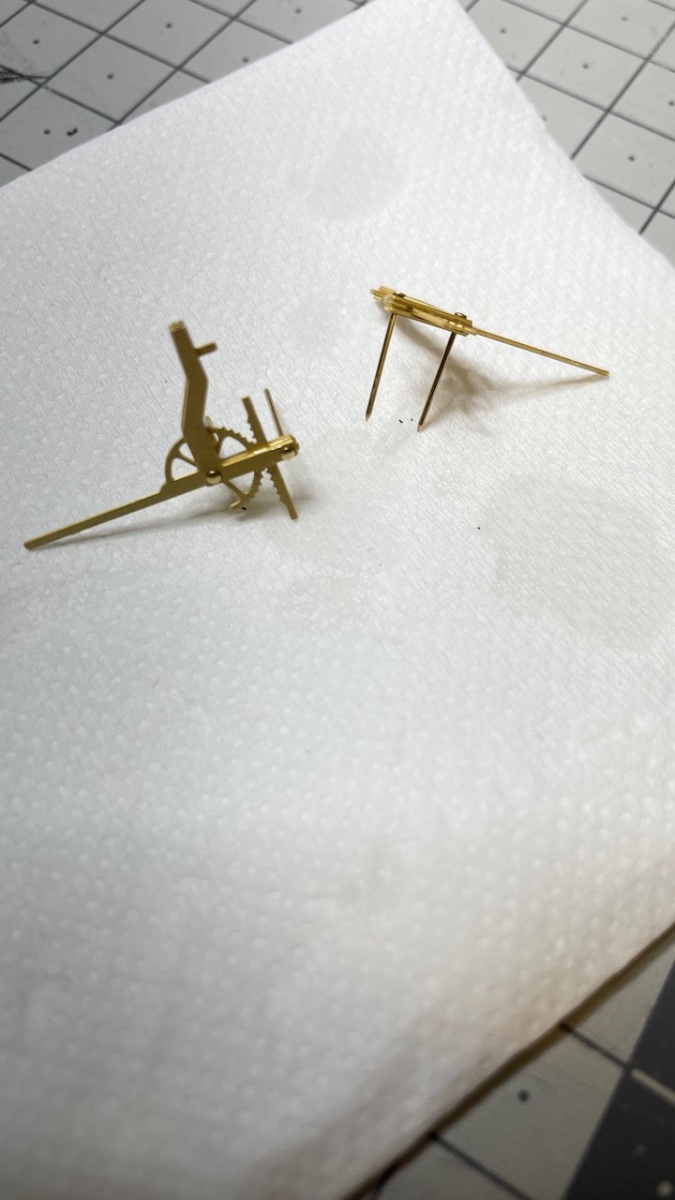
Next is the construction of hand pumps.
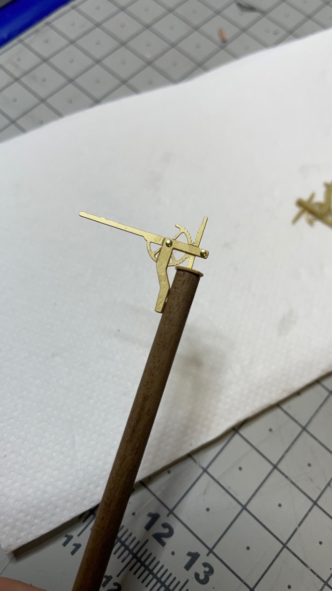
Photo 516: These are the parts. Wood from 4mm dowel. Visible area varnished.
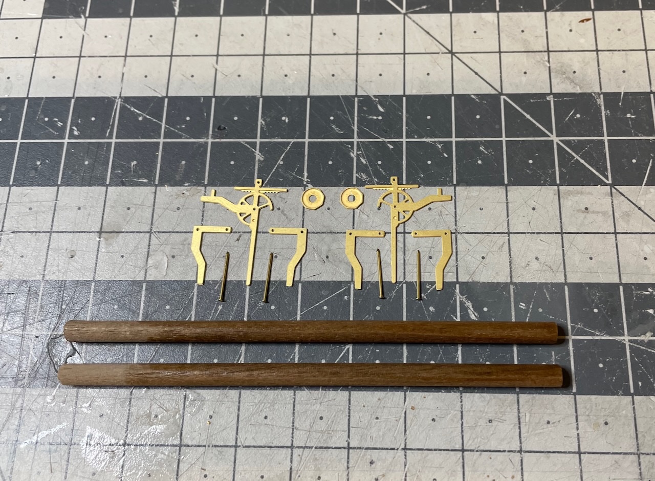
Photo 517: This is the positioning of PE parts, before gluing together.
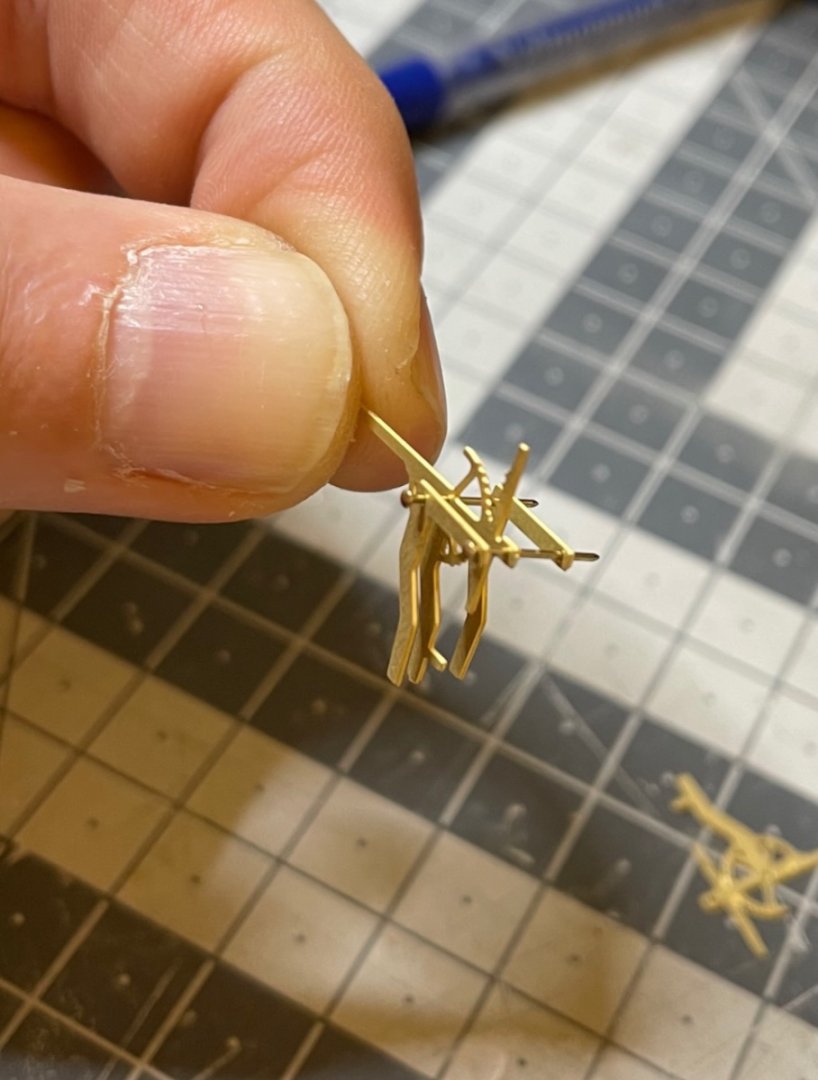
Photo 518: Glued together. The excess pin tips will be trimmed. I had to use a 0.6mm hand drill very gently to open the holes just a little in order to avoid the risk of bending the parts accidentally by having to push the pins too hard.

Photo 519: I use this "micro" marker to mark the drill spot, in this case to mark the center of the tip of the dowel...

Photo 520: ... like this.
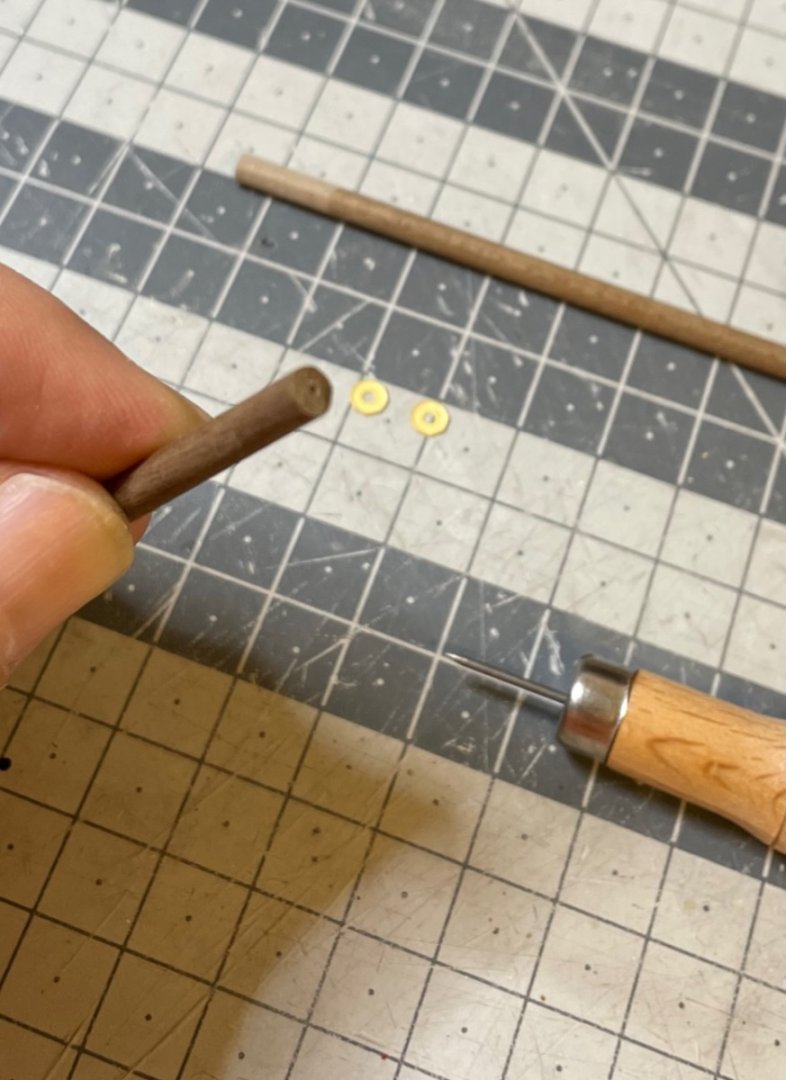
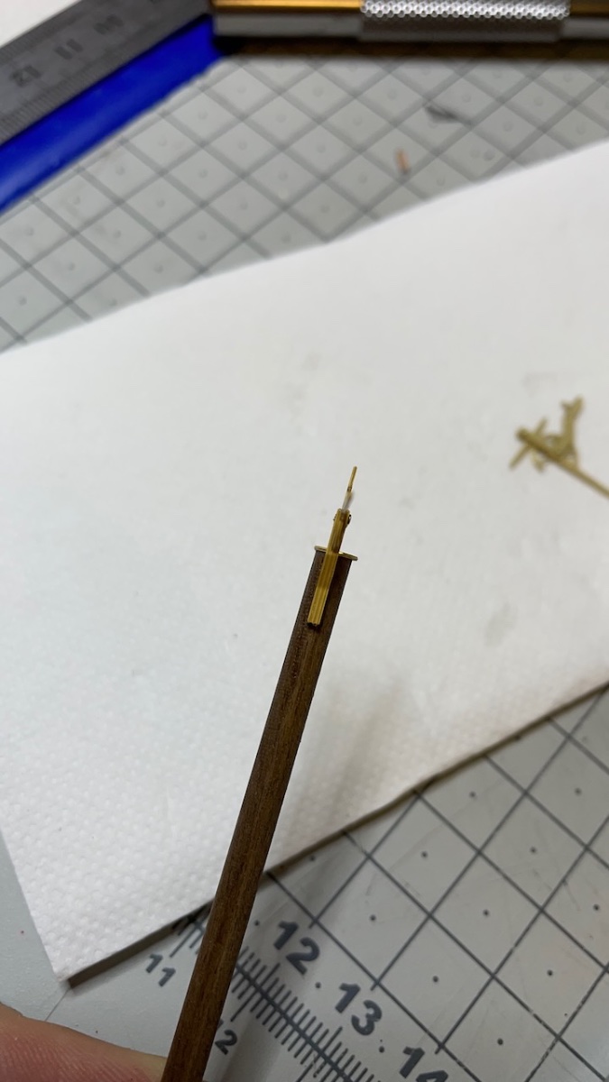
Photo 521: The top cap glued, another hole on the side after some measurements.
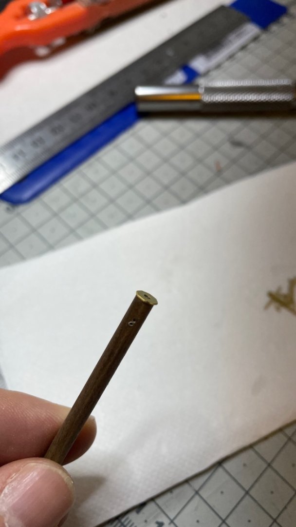
Photo 522 - 523: The pumps installed on the dowel.


Photo 524: .. .and installed in place. Follow the plan to ensure correct orientation.
- Cirdan, etubino, Haliburton and 2 others
-
5
-
-
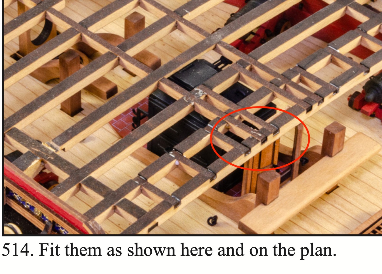
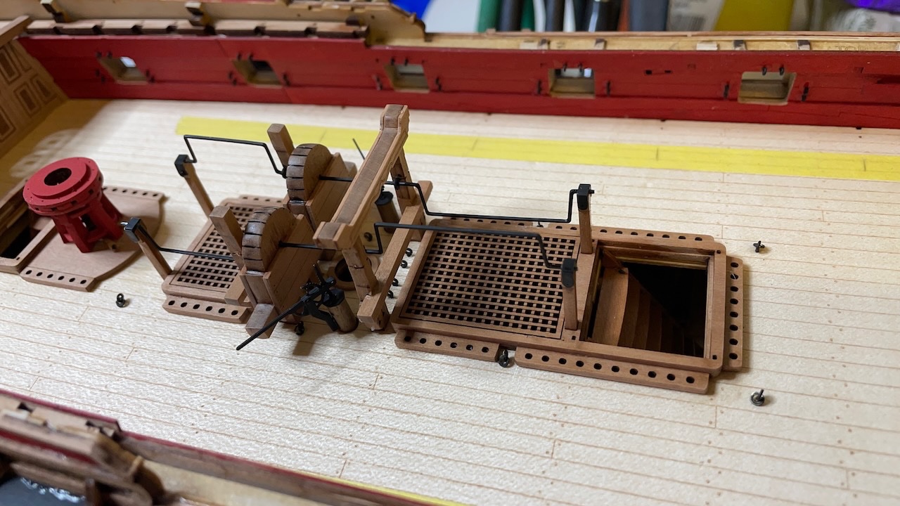
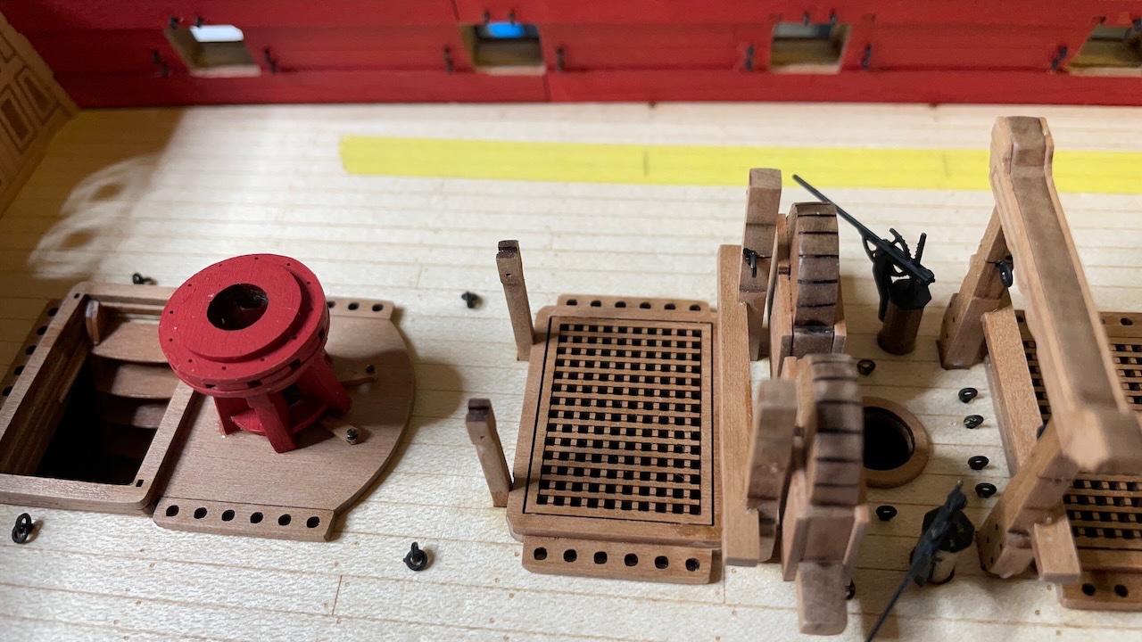
Photos 513-514: Chain pump main patterns, cleaned and glued in place.
- ccoyle, James G, Knocklouder and 5 others
-
8
-
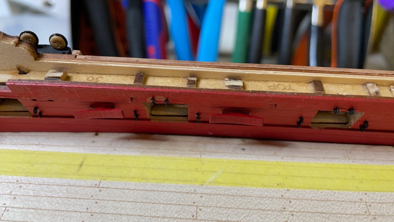
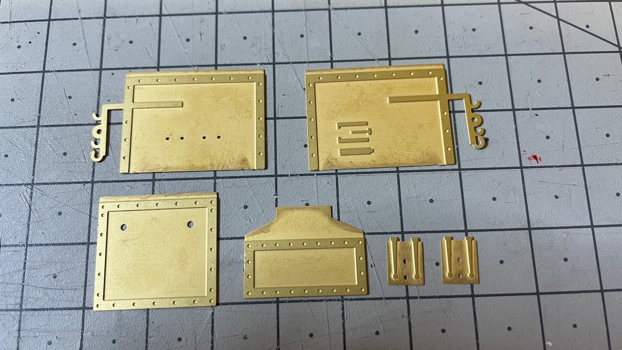
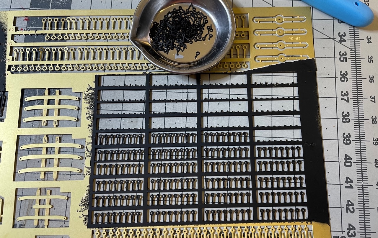
Before I forget and too late, I need to pin the eyebolts around inner gun ports.
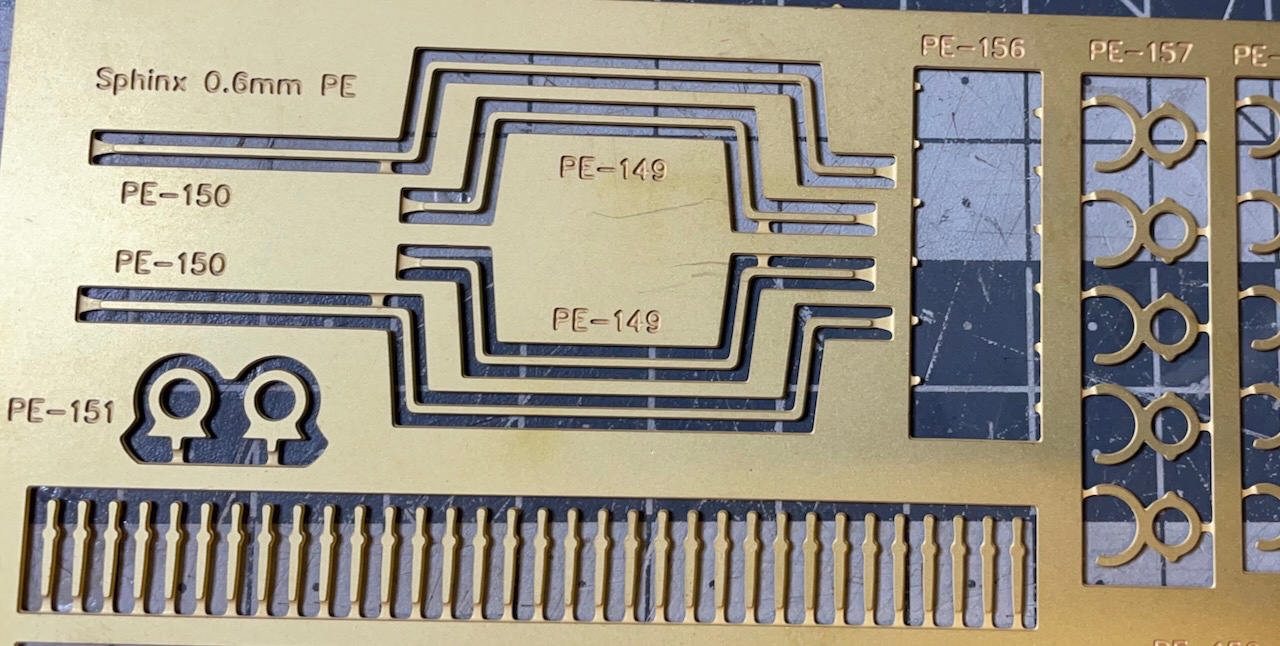
Photos 511-512: The eyebolts are on the PE sheet, not stock. Extraordinary for a model kit and I like it. I had already spray painted them earlier.
- Prowler901, Cirdan and mtaylor
-
3
-
Build Day 50: 2.5 hrs / Total 113 hours
50 build days are behind! (champaigne!)
Checking my first post from June 21st of this year, on the average I have been spending time with this model almost once every four days and posting about 10 photos per build session.
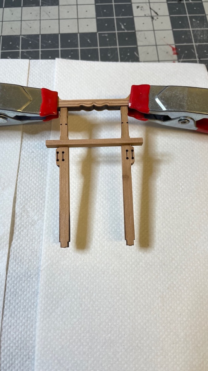
I continue adding the constructions on the deck, many with exotic names beyond my ship building vocabulary, I have to double check to make sure I spell them correctly 😆. For example next ones are "Chain Pump Handle Stanchion", "Main Jeer Bitt Posts" and "Main Bitts Cross Beam".
I also apply matt varnish on these constructions as I glue them in place. I haven't applied any varnish on the deck surface, at least not yet. Any ideas when is the good time? Or do you apply it at all? I consider it mainly for protective purposes.
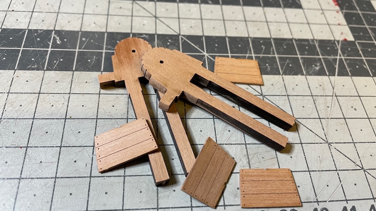
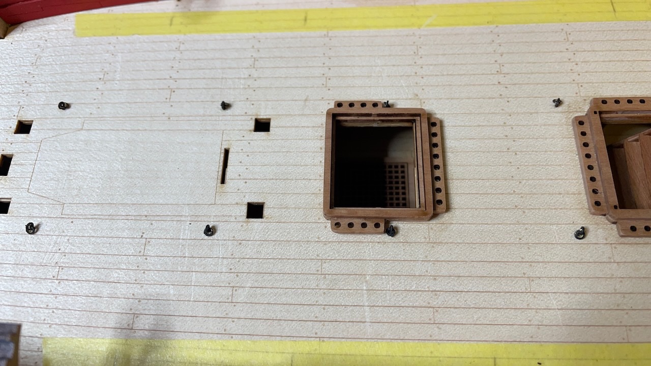
Photos 505-506: Use the photo etched part for a reference to drill and put it aside for now. It will be glued back later.
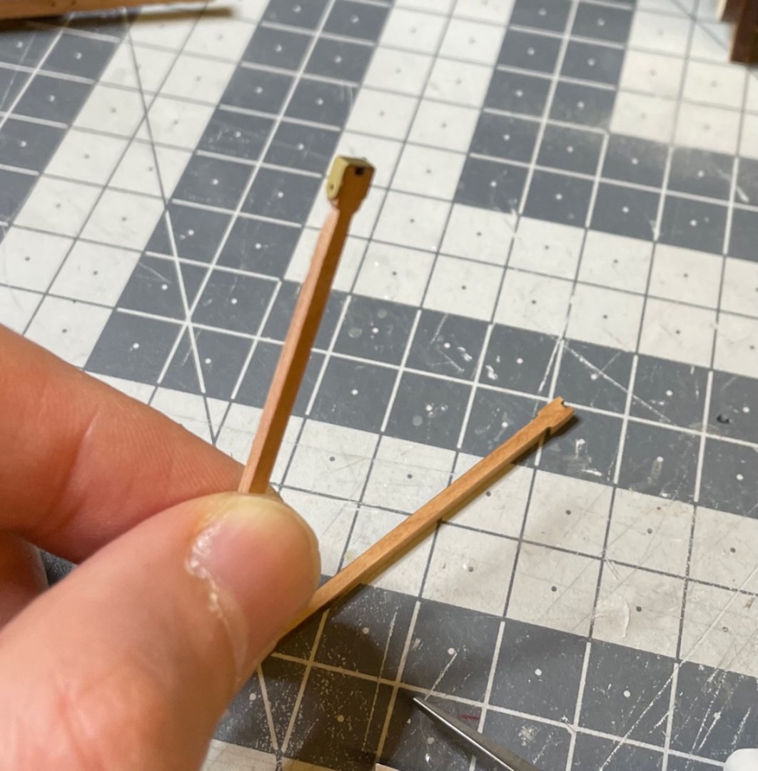
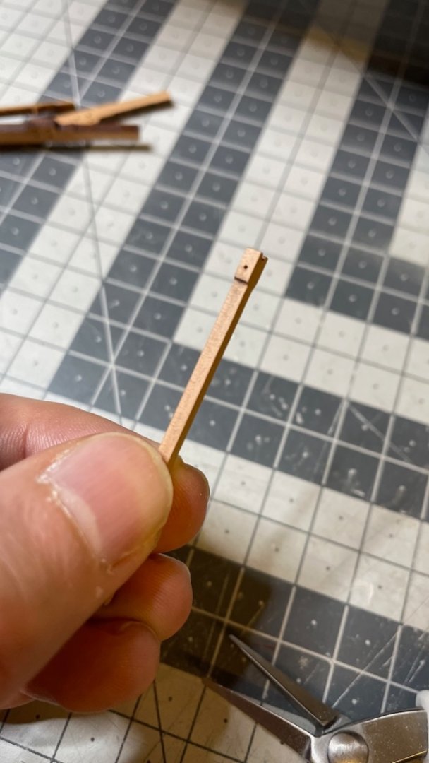
Photo 507: Glued in place. The feet go down all the way to the holes in the lower deck. With just a tiny amount of filing, I can say they fit extremely precisely.

Photos 508-510: Cleaned the and glued the next ones in place, same way as the previous parts.


HMS Sphinx 1775 by aydingocer - Vanguard Models - 1:64 - Revision #2
in - Kit build logs for subjects built from 1751 - 1800
Posted
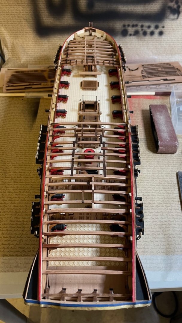
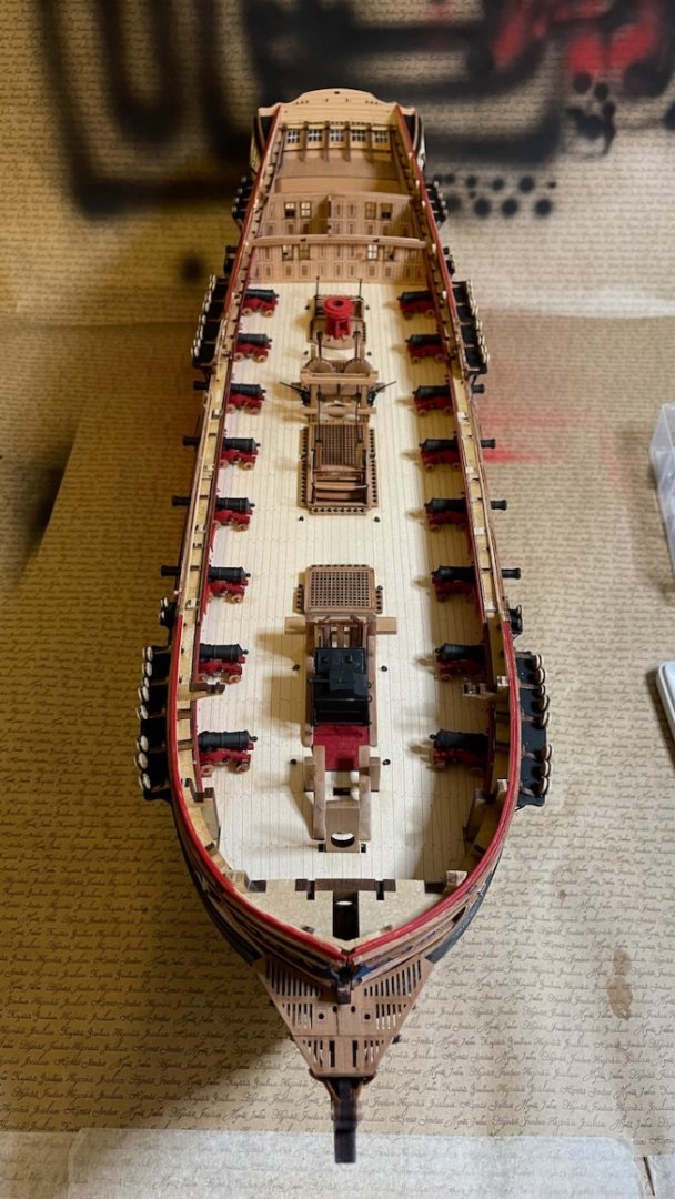
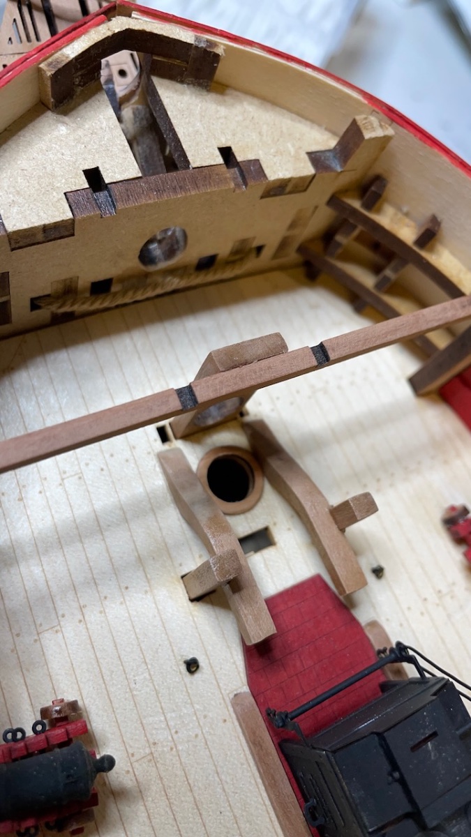
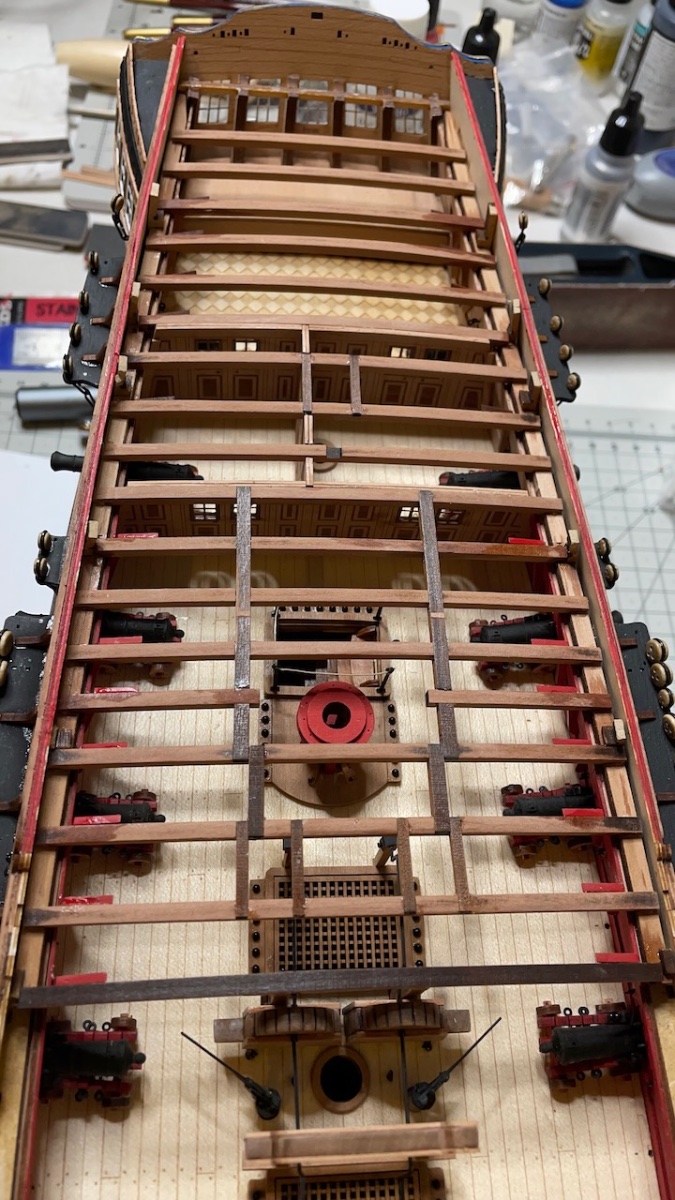
Photo 588 : All deck beams in place.