


aydingocer
-
Posts
898 -
Joined
-
Last visited
Content Type
Profiles
Forums
Gallery
Events
Posts posted by aydingocer
-
-
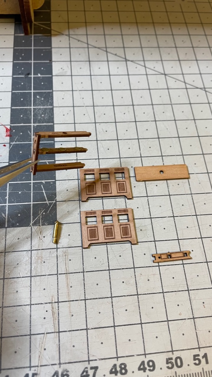
Build Day 65: 1 hour / Total 152 hours
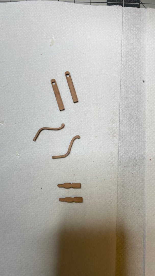
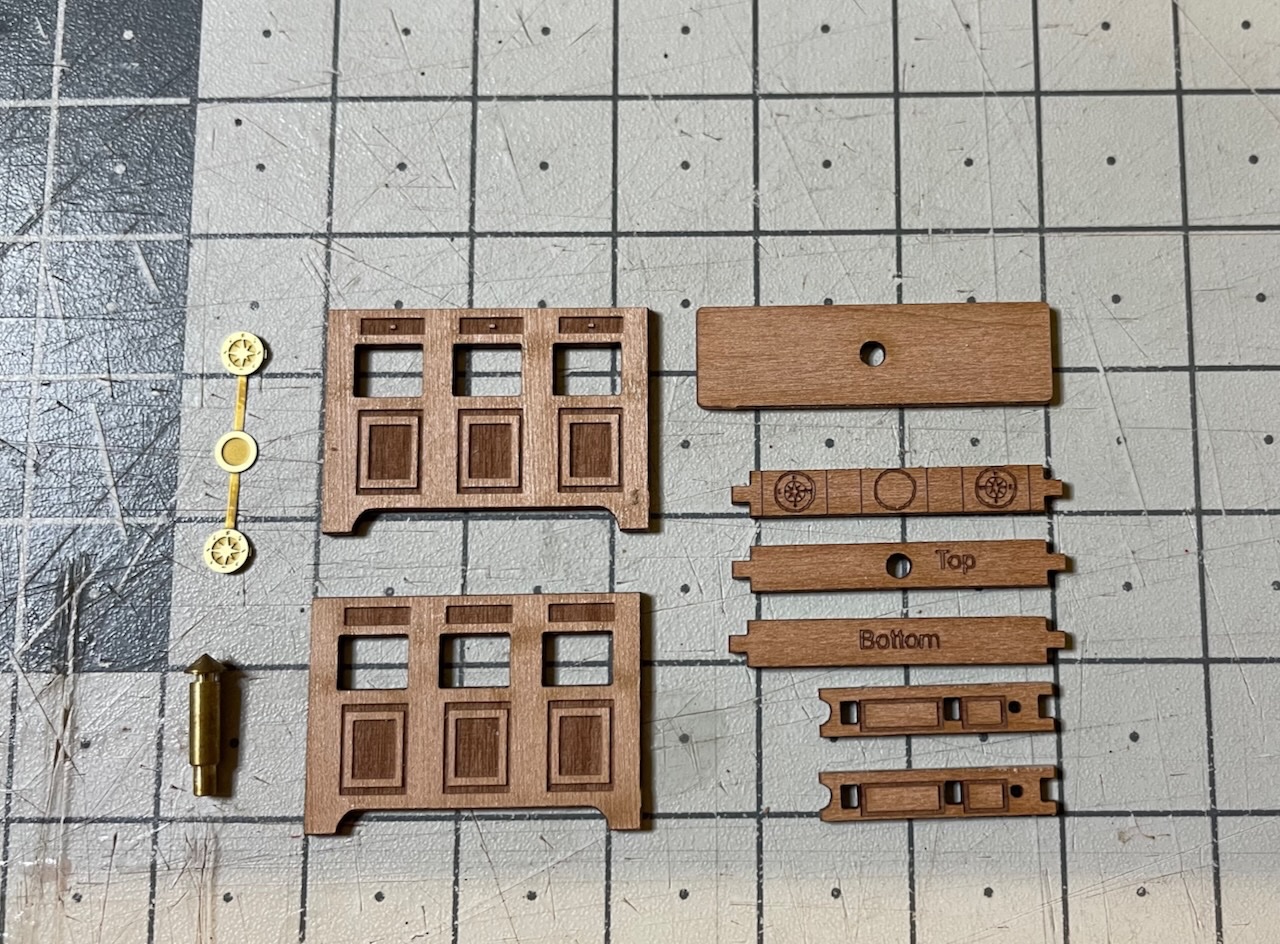
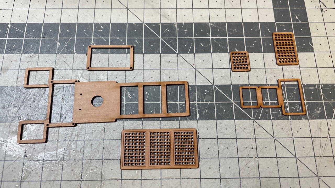
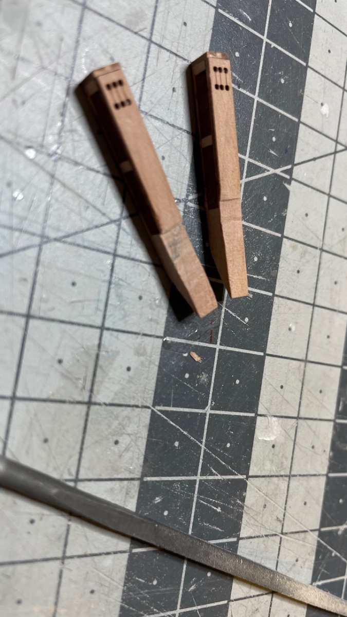
Photos 570-571: Remaining Quarterdeck breast rail components.
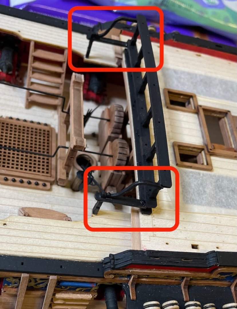
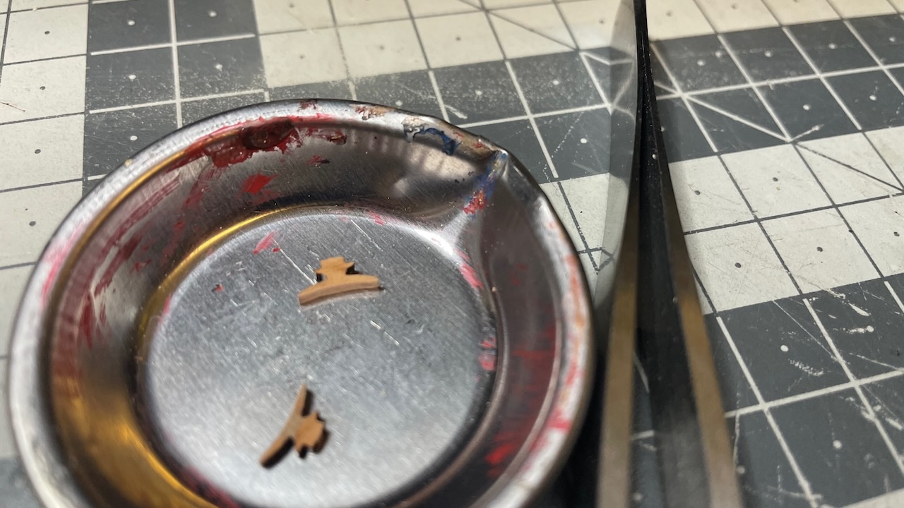
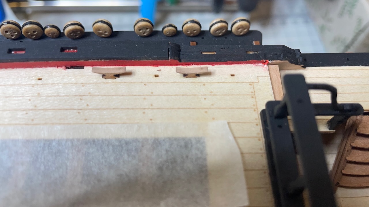
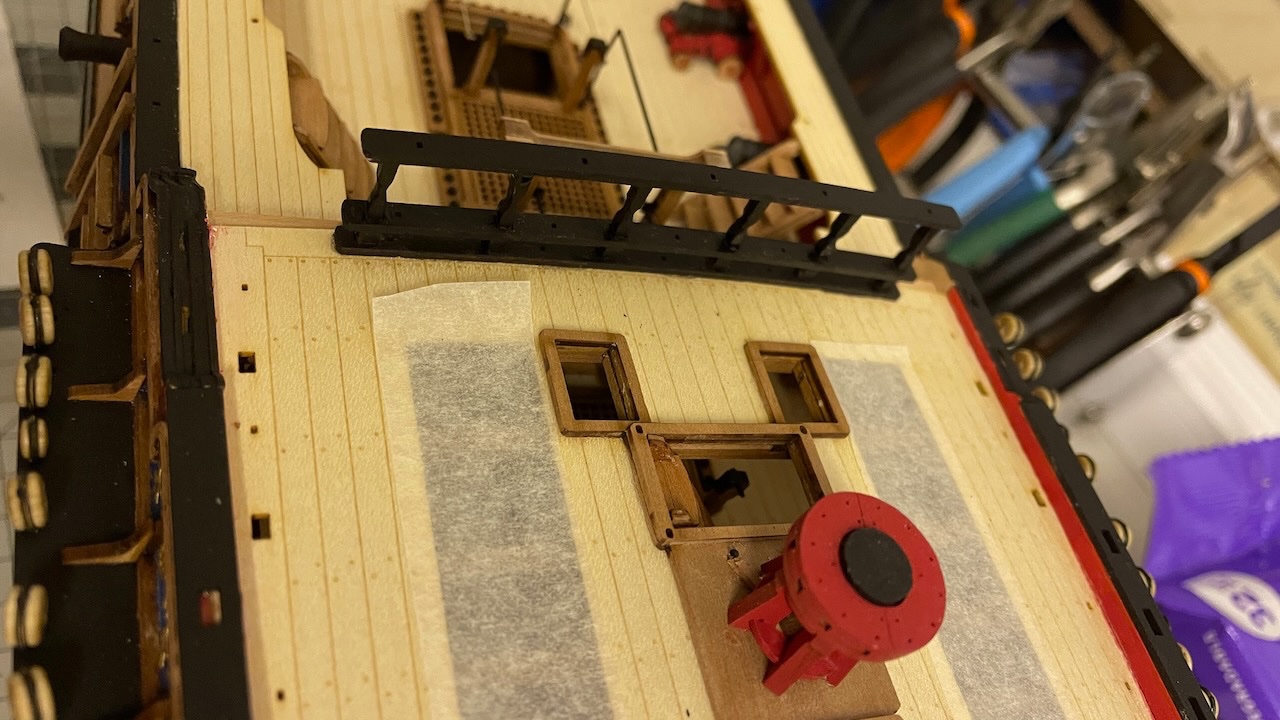
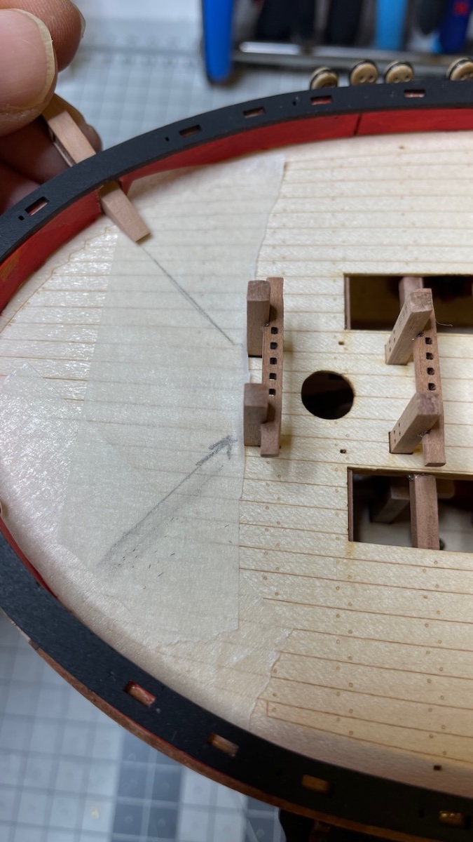
Photos 572-573: Deck eyelets and cleats in place. These cleats are not painted hence they need laser chars removed. Eyelets will be visible in the future photos.
That's all for today. Thanks for watching!
-
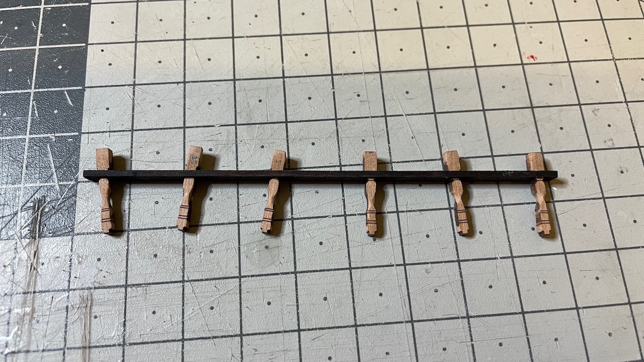
Quarterdeck breast construction.
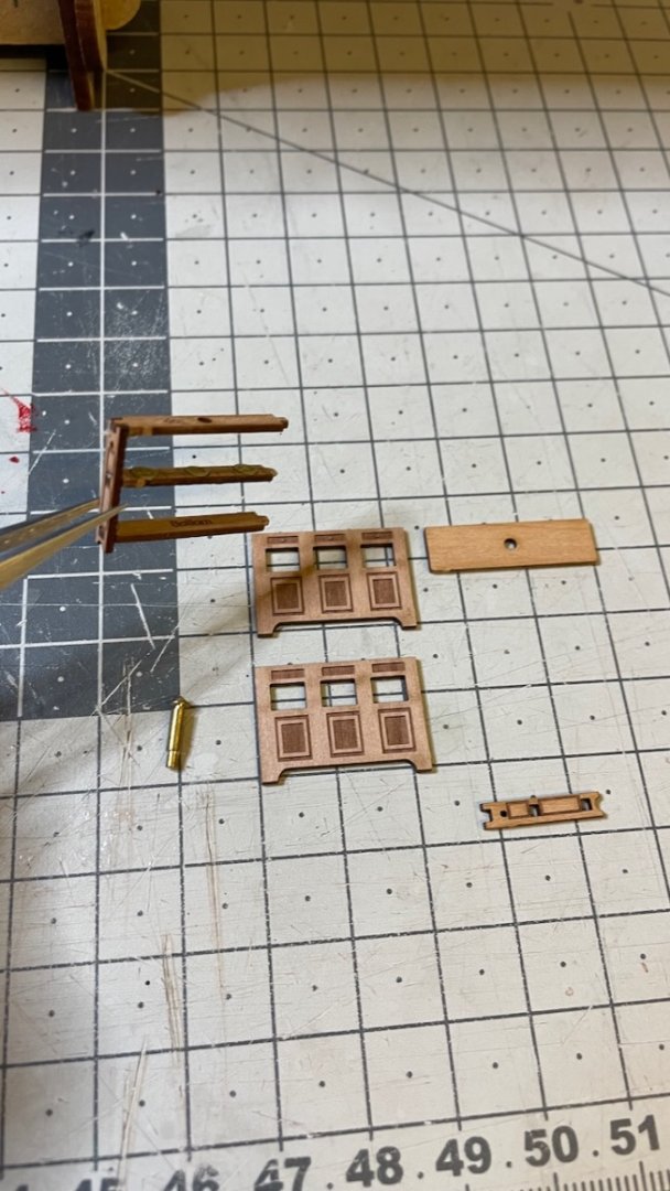
Photo 654: Parts removed and prepared for paint, labelled to avoid mixing them up.
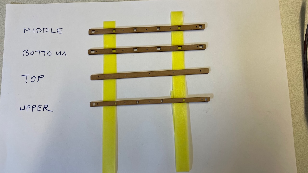
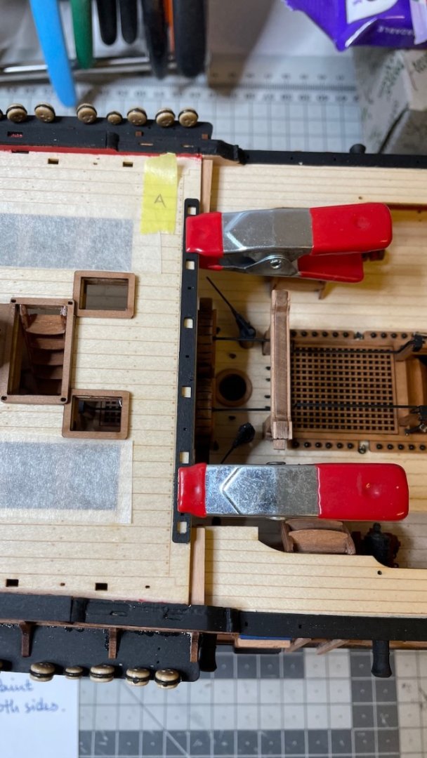
Photo 655: Lower rail in place. I referred to the plan to determine the order of the stanchions and marked with a tape the position of part A.
Photos 656-657: The stanchions go A, B,..F. Though they are almost identical, they differ slightly in the bottom, where they follow the curvature of the deck.
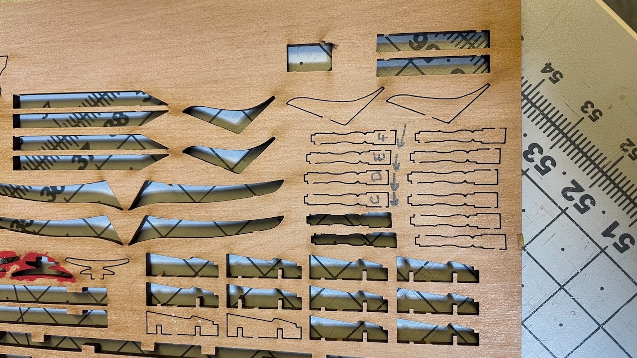
Photo 565: You'll need to round the "belly" of the stanchions in the shape of a round pillar. Here is one done. I used the file in the photo for this.
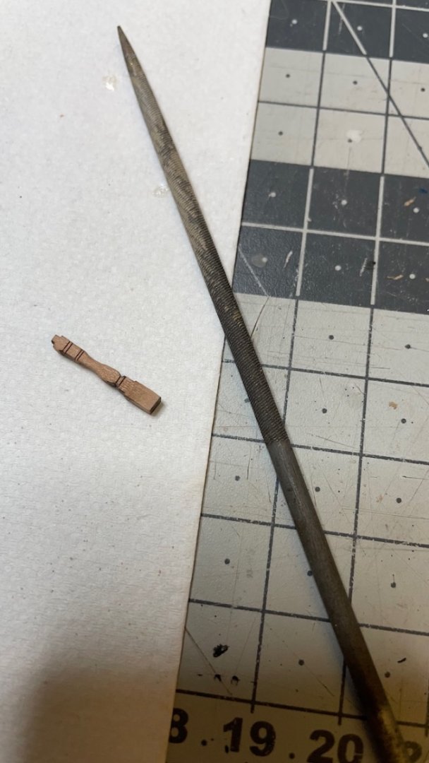
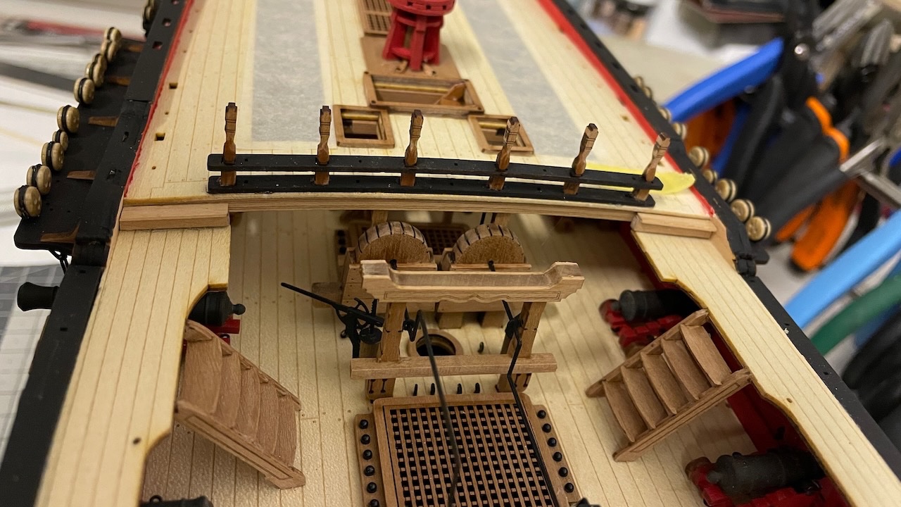
Photo 566: I inserted the stanchions already to the middle rail before glueing them in their places. Note they are not glued to the middle rail yet. They move freely. This will allow me to make alignment adjustments easily.
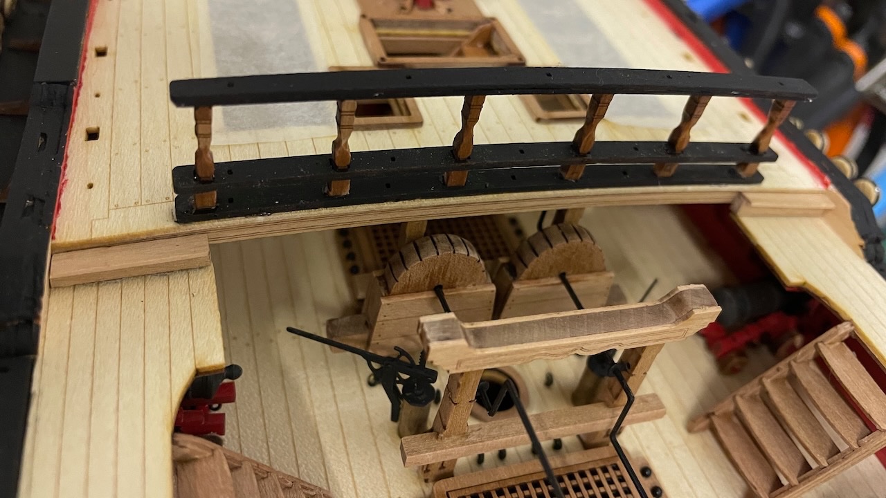
Photos 567-569: Stanchions and remaining rails are in place. Further, I painted the stanchions in black.
That's all for today. Thanks for watching!
-
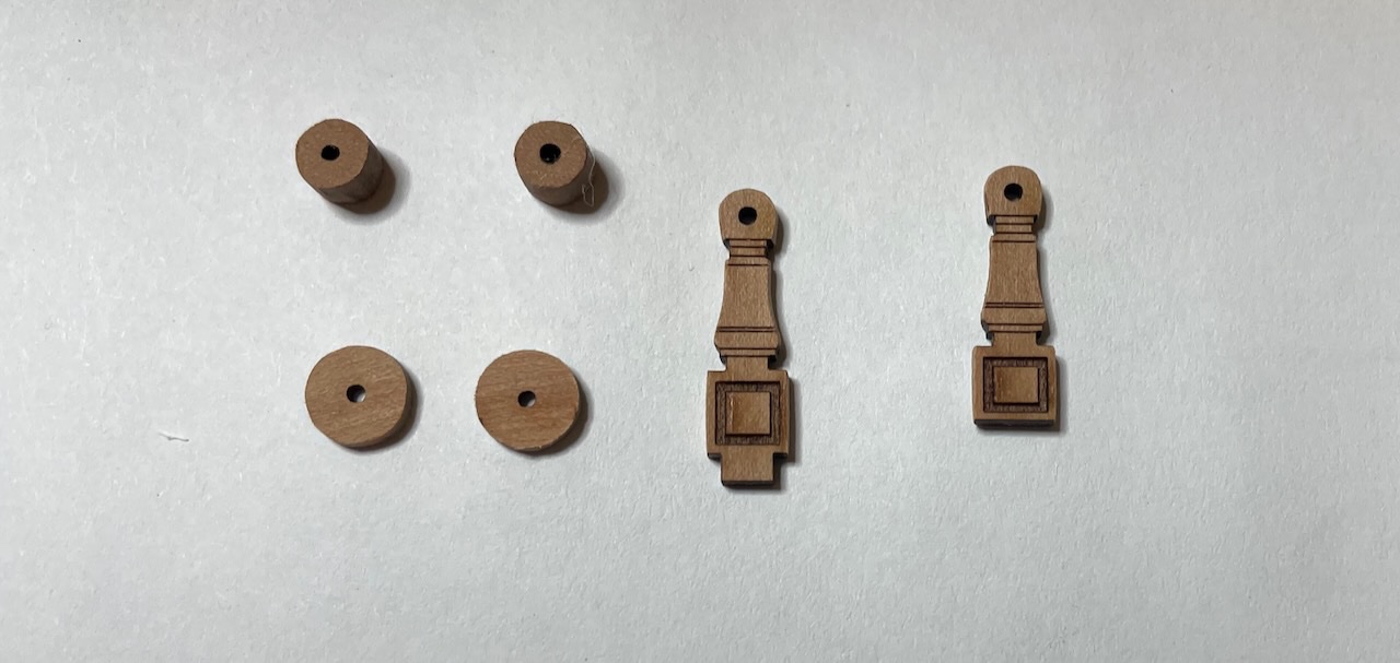
Photos 652-653: Binnacle in progress. Photos of the complete structure is missing at the moment.
- Glenn-UK, mtaylor and Prowler901
-
 3
3
-
Build Day 64: 4,5 hours / Total 151 hours
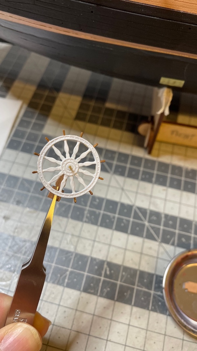
It was a productive Sunday today with 4,5 hours of build. I completed the Ship's Wheel, Binnacle and Quarterdeck Breast.
I am writing this log after I have closed my workbench for the day and covered the model, and I have noticed that I didn't take any photos of the Wheel and Binnacle constructions in their place. I will take and post those photos later.
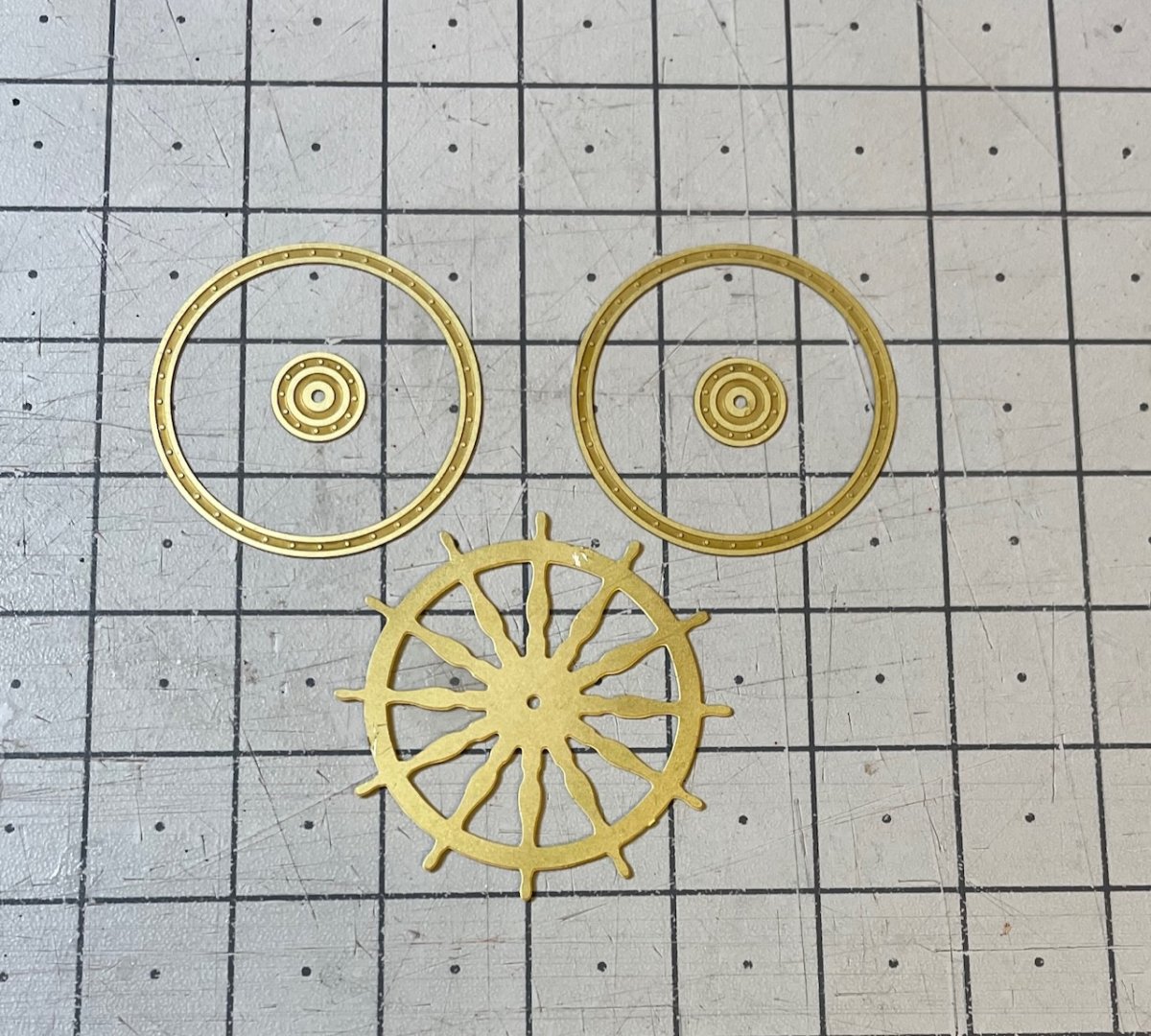
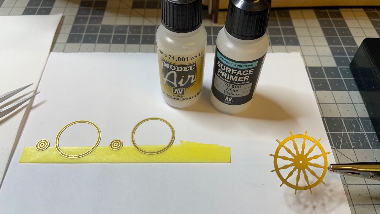
Photo 648-651: Ship's wheel. I used white primer followed by the white paint. Once dry, I applied walnut color to the handles.

- Prowler901, mtaylor and Glenn-UK
-
3
-
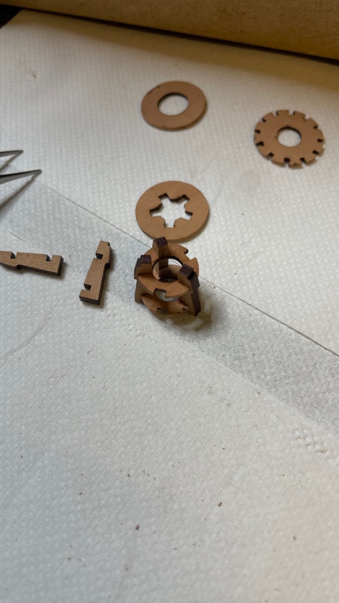
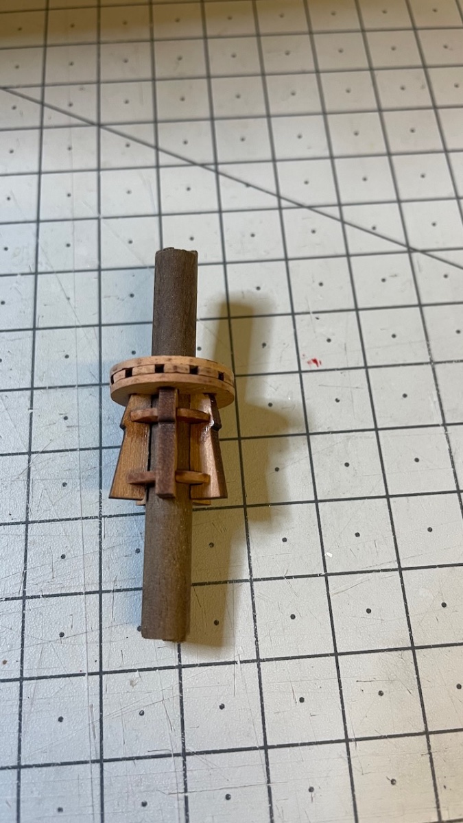
Build Day 63: 1 hour / Total 146.5 hours
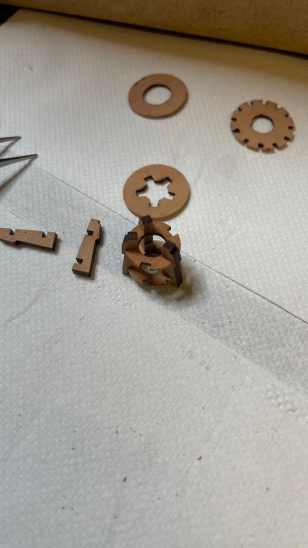
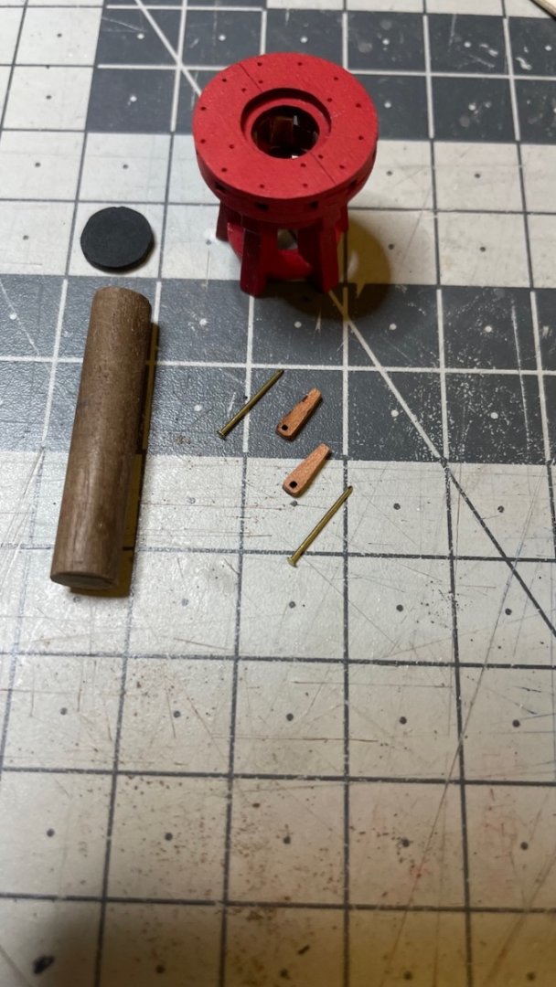
Photos 644-647: Yesterday I spent around one hour building and installing the upper capstan. The steps are similar to the previous one.

- mtaylor, Glenn-UK and Prowler901
-
3
-
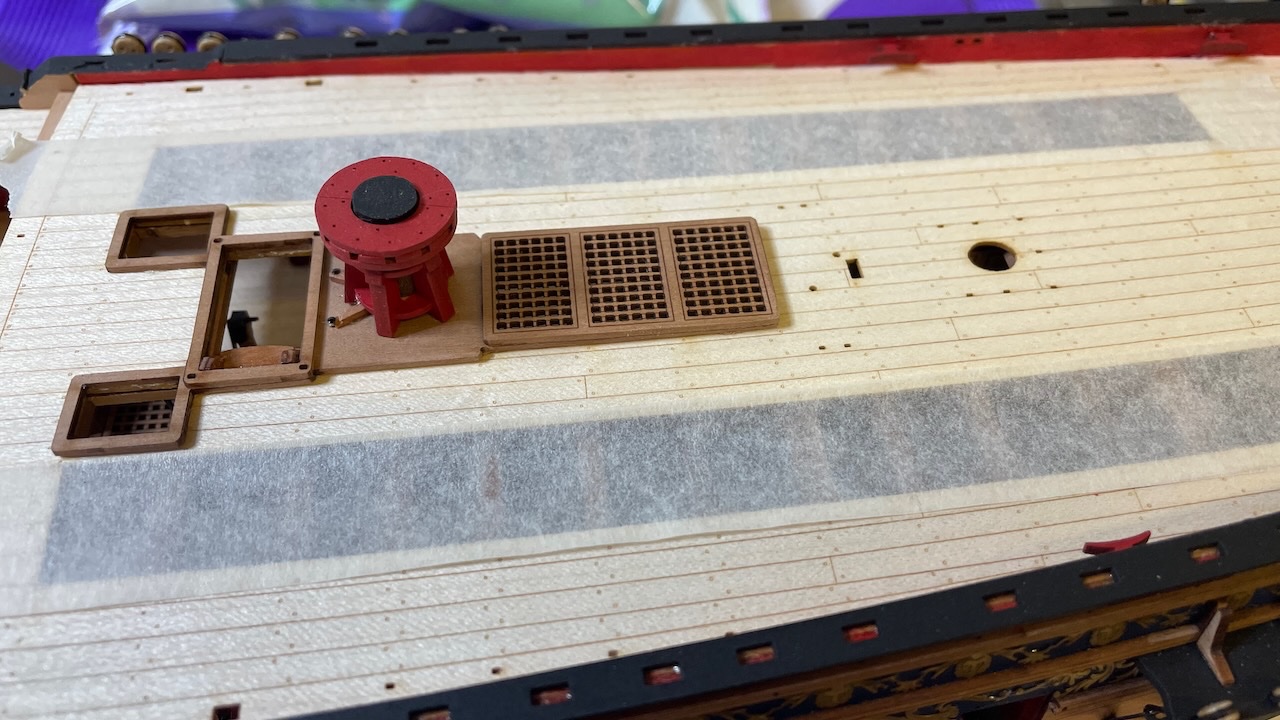
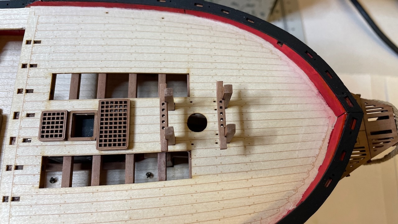
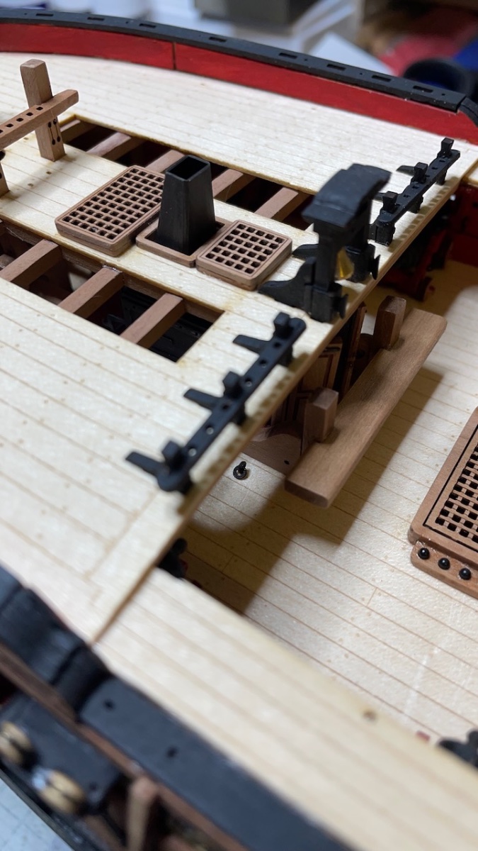
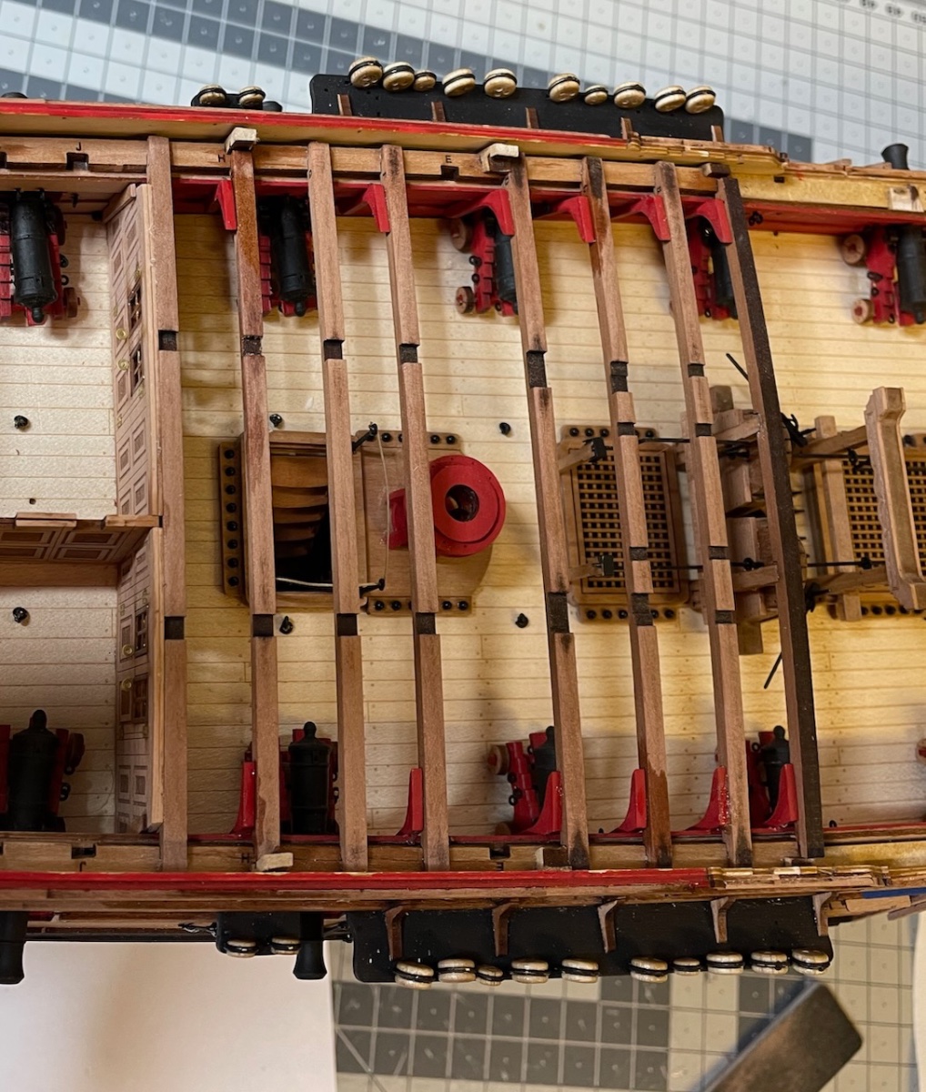
Photos 642-643: Ended the day by gluing the stove flue and Quarter deck gratings in place.
I missed the slot on top of the stove due to some minor alignment errors, but I just removed off the socket on the bottom of the flue and glued it on top of the stove. No issues.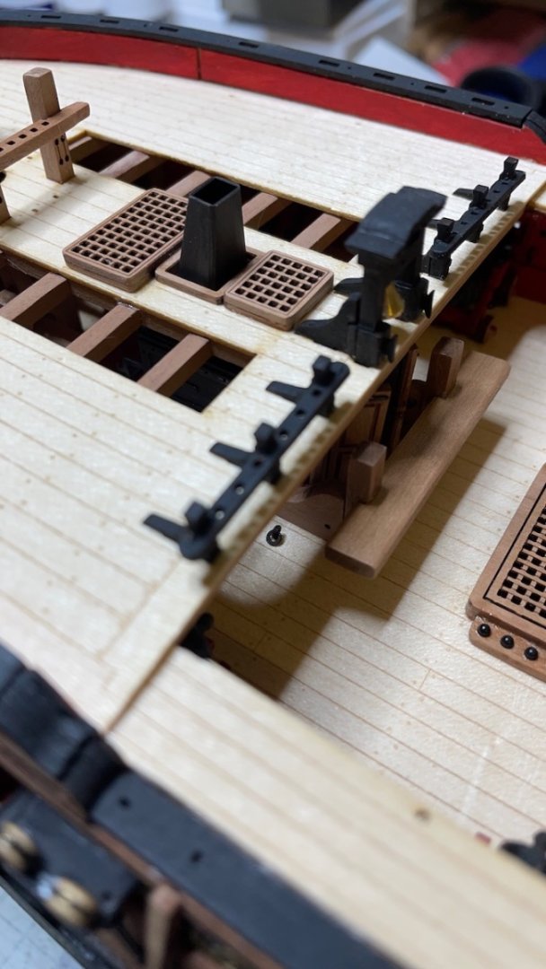
That's all for today. Thanks for watching!
- Cirdan, Paul Le Wol, mtaylor and 3 others
-
6
-
Build Day 62: 1,5 hours / Total 145.5 hours
I finished Catheads. In the last few minutes of my session I glued stove flue and Quarter deck gratings, all those I had prepared earlier, in place.
Photo 633: Enlarging up the pre-opened holes for the catheads.
Photo 634: Tools I use for this purpose. The blue file is a micro size file that easily fits the hole. After a few strokes I switch to the bigger square file, time to time scraping with the knife.
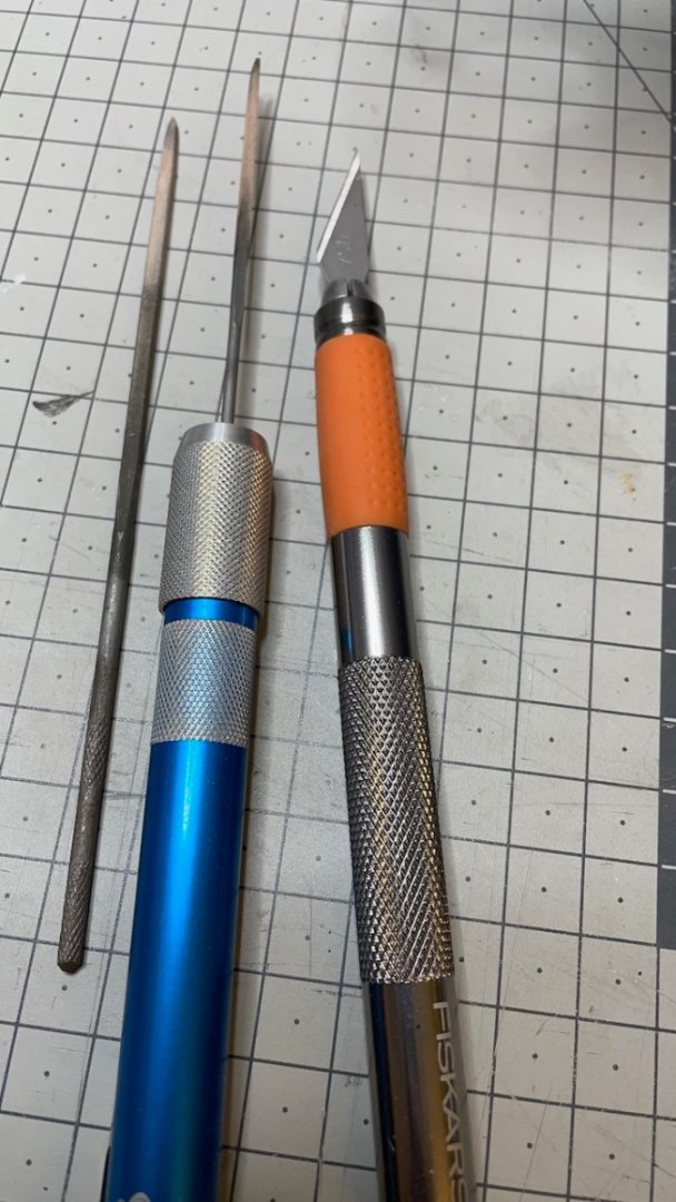
Photo 635: I also used this trick of filing the catheads themselves at points where I did not want to mess with the opening. These sections will be hidden in the Gunwale.

Photo 636: I drew reference lines on the masking tapes to help me while opening the holes to make sure that the Catheads align at correct angle.

Photo 637: You'll need to trim some of the decoration for fitting the support knees.
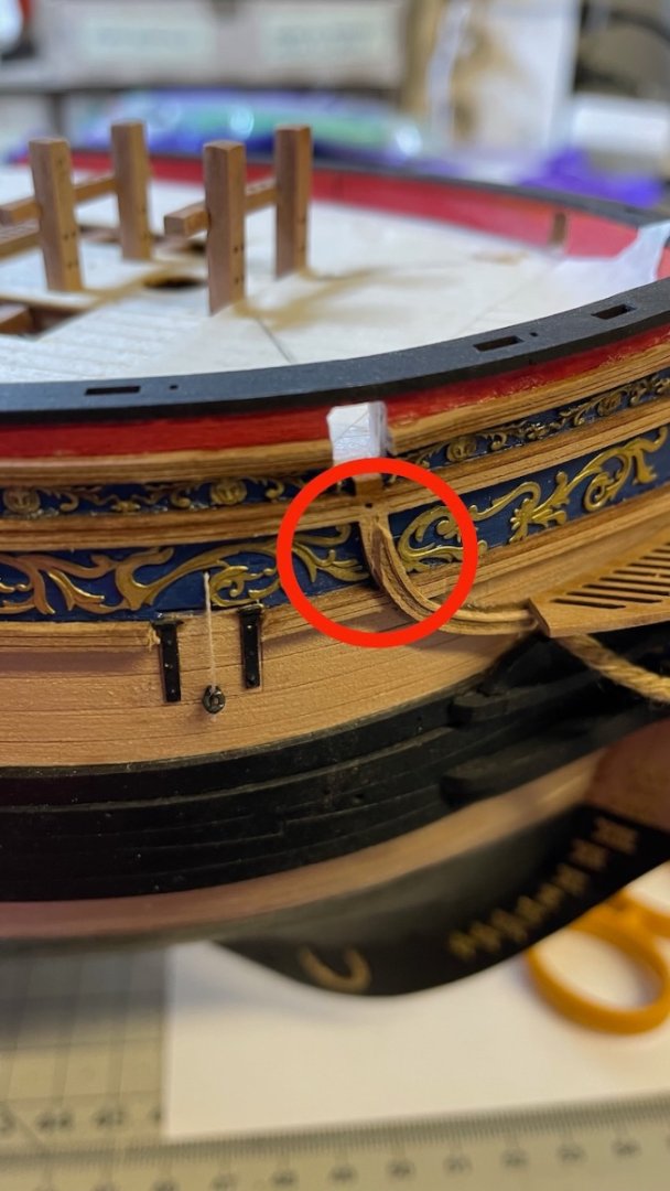
Photo 638: Parts painted...
Photos 639-641: ... and glued in place.

- mtaylor, Cirdan, Prowler901 and 1 other
-
4
-
Catheads.
Photo 627: Parts that form two Catheads... and some more (See next photo)
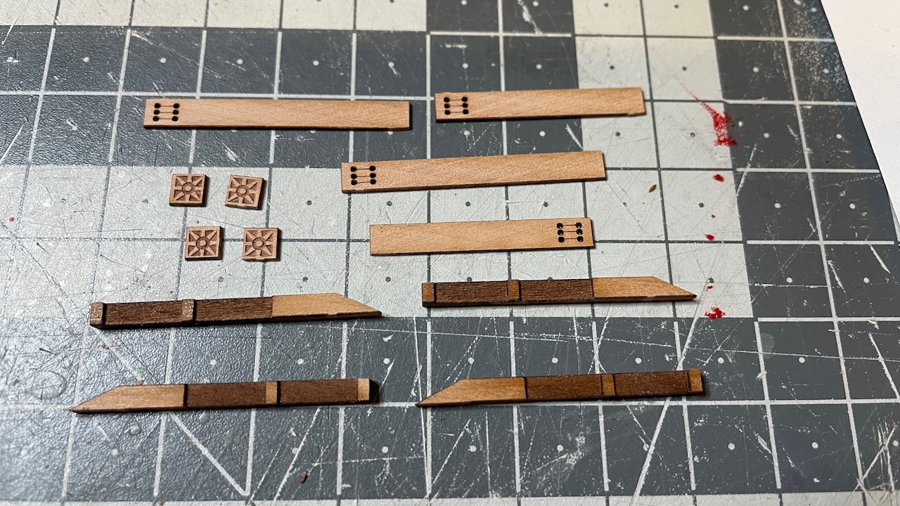
Photo 628: I figured I removed two end mouldings too many (those square ends). I taped them back to the sheet so they won't get lost. I don't know yet if I need them later or if they are just spares. But they are just safely there in case.

Photo 629: First you glue two parts back to back like this...
Photo 630: ... then glue the short and long patterns on their respective matching sides...

Photo 631: ... and glue the end mouldings.
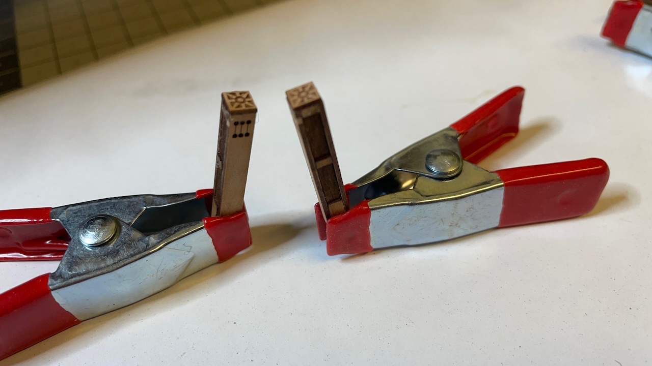
Photo 632: ... and sand the sides to level.

That's all for today. Thanks for watching!
-
Build Day 61: 1,5 hours / Total 144 hours
Today I spent 1,5 hours making the Forecastle rails at either side of the Belfry and started Catheads.
Photo 624: Parts that make the Forecastle Rails.

Photos 625-626: The stanchions sit on the rails with a slight angle to comply with the deck curve.
I painted the rail+stanchions construction before installing in place. Same for the supporting knees.

-
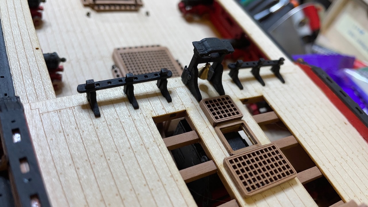
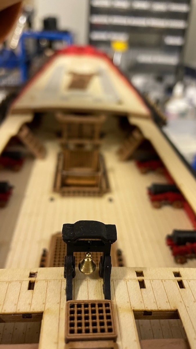
Belfry installation.
Photo 617: Parts. Two nails will be used for alignment of the parts...
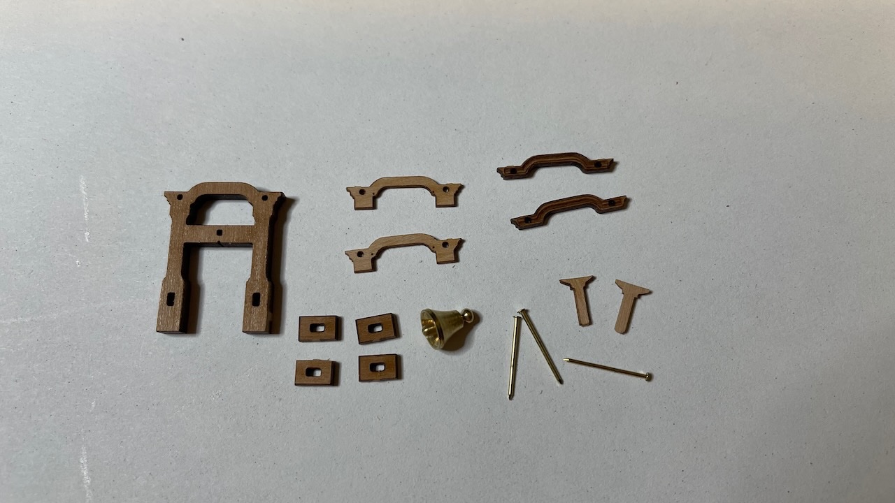
Photos 618-619: .... like this. I just applied a drop of thin CA and left the nails in place and trimmed them flush with the surface.

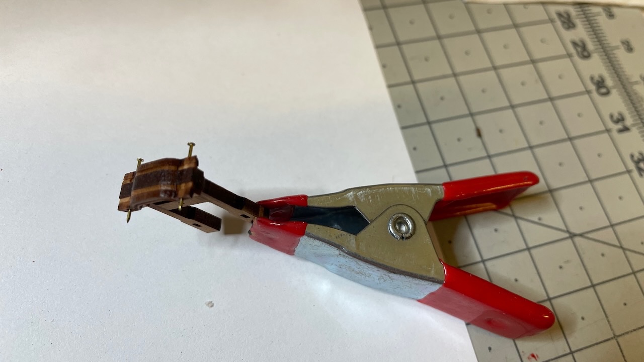
Photo 620: Bell is hanging by means of the third pin, bent 90 degrees
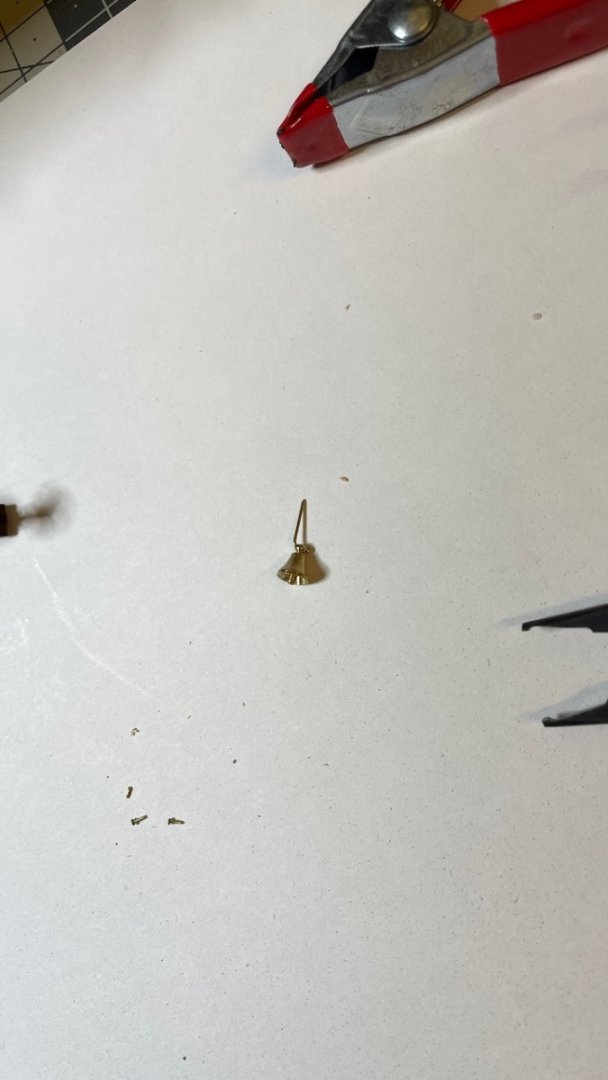
Photo 621: I chose to paint it in black.
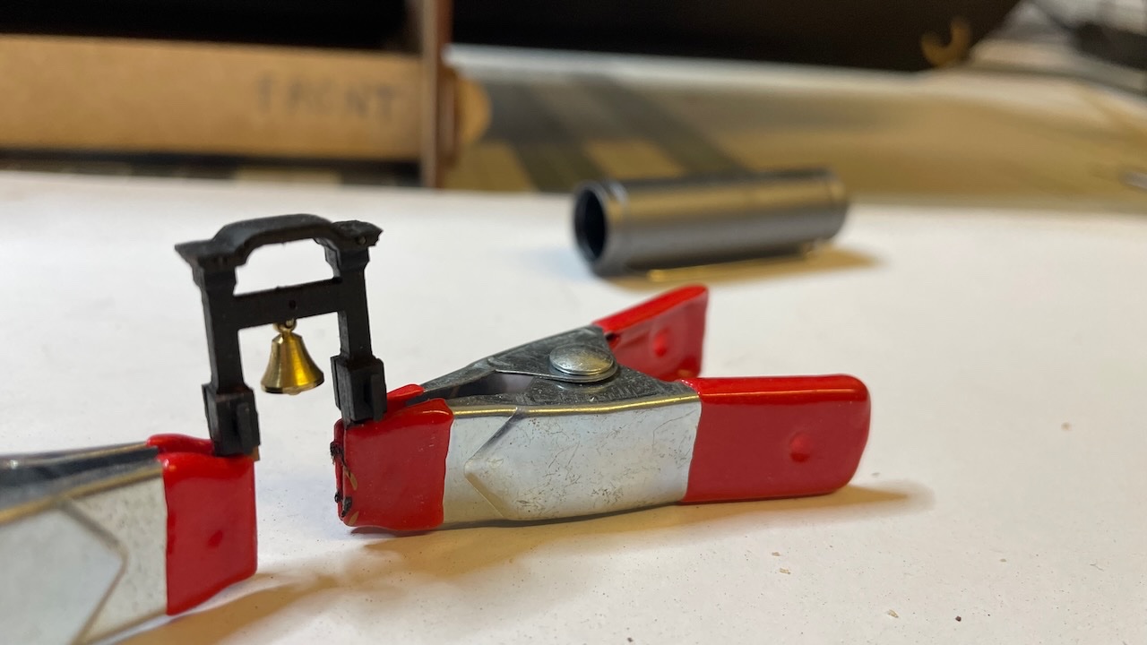
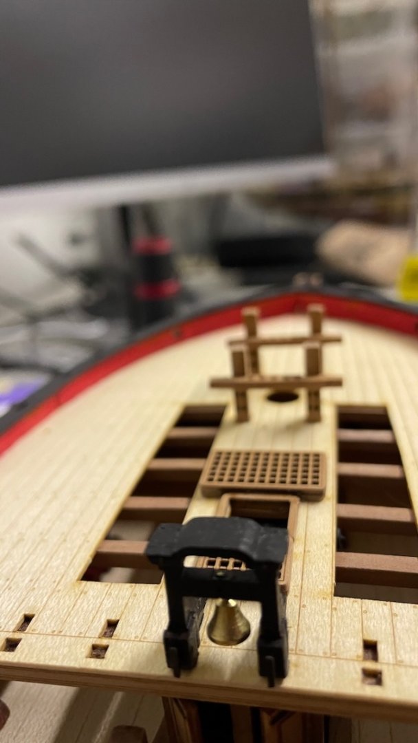
Photos 622-623: Belfry in place together with support knees, also painted in black.

That's all for today. Thanks for watching!
-
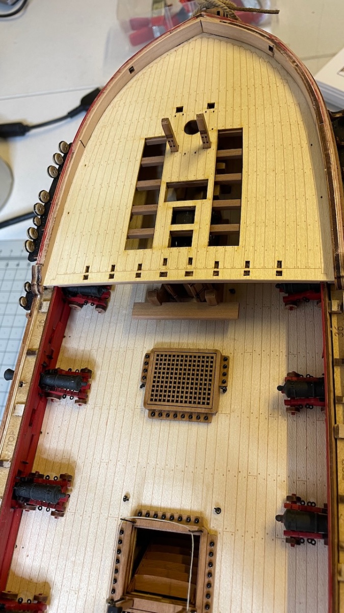
Photos 615-616: Forecastle and Quarterdeck gratings. Forecastle glued in place. According to the instructions the Quarterdeck gratings will be glued later, though I don't think it is critical to follow that order.
Cleaning the laser char on the edges takes most of the time with these.
- Glenn-UK, mtaylor, Prowler901 and 1 other
-
4
-
Forecastle, Quarterdeck and Waist gunwales.
Photos 611-612: Parts, painted with airbrush.
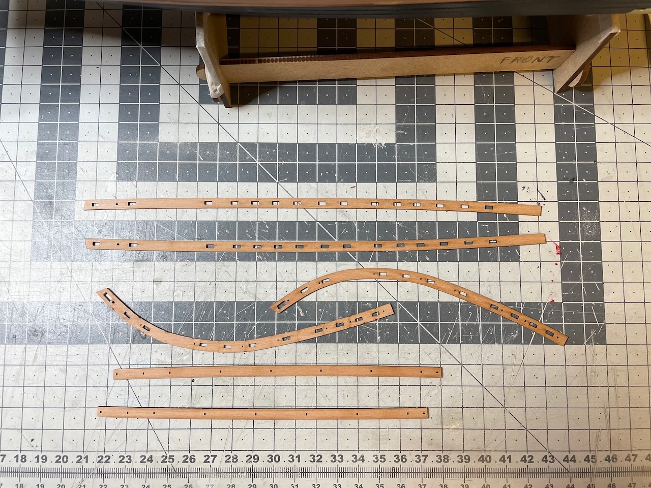
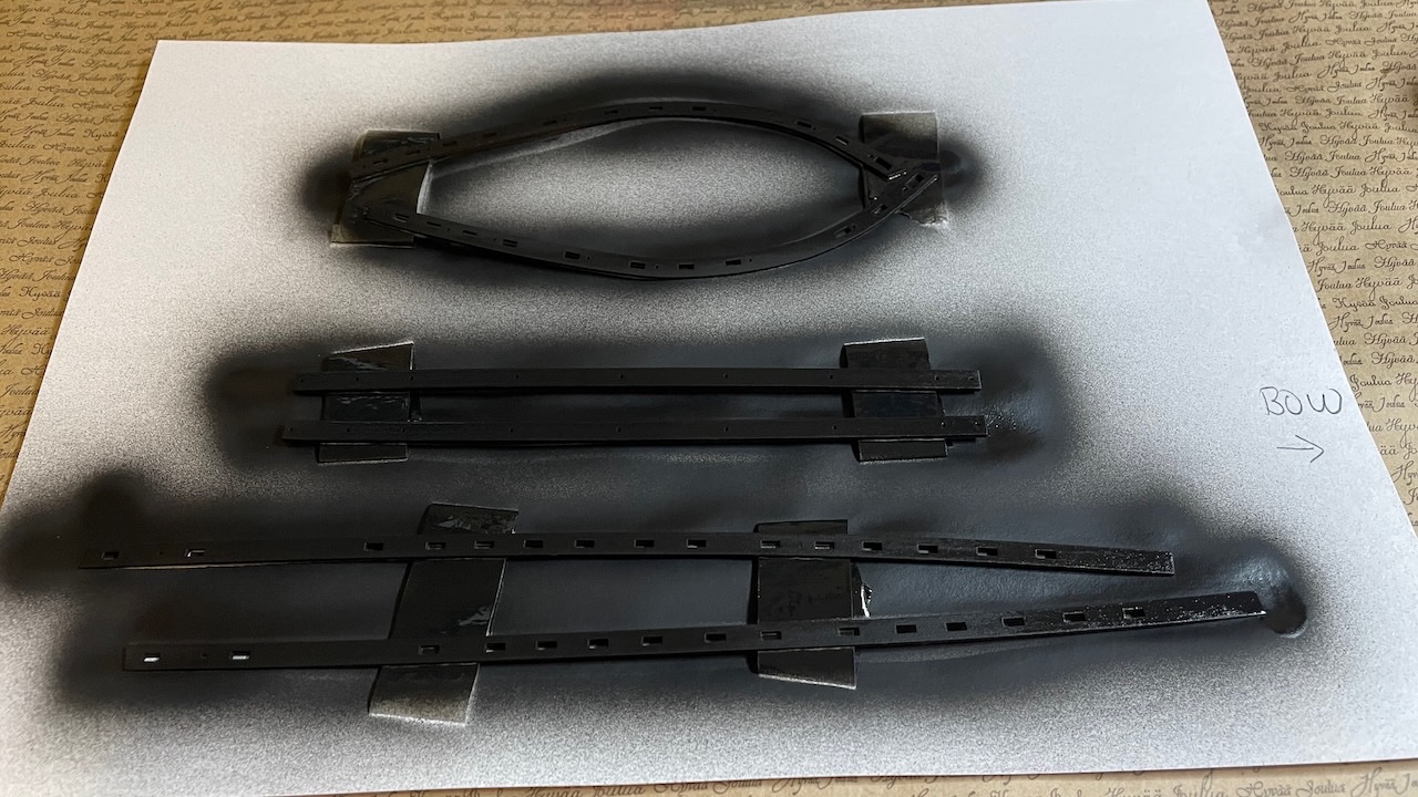
Photo 613: While the paint is drying, I smoothened the scrollwork on the bulwarks, using filler, file and sandblock. This area is to be painted in black, as continuation of the gunwales. Note there are two slots that need to stay, so no filling in them.
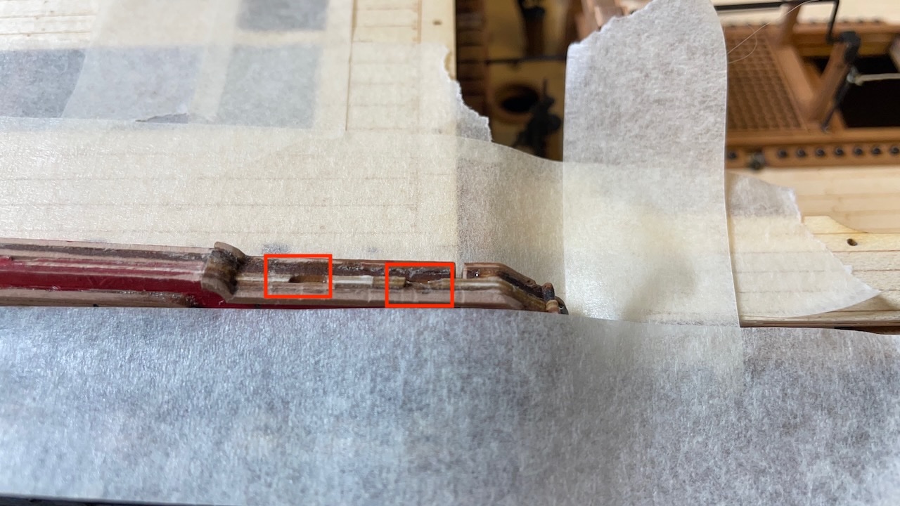
Photo 614: Gunwales glued.
- mtaylor, Prowler901, Knocklouder and 3 others
-
6
-
Build Day 60: 4 hours / Total 142,5 hours
Thanks to the rainy Sunday (!), I managed to work quite a many hours today, completing:
- Fore Topsail sheet bitts with their cross beams,
- Forecastle, Quarterdeck and Waist gunwales installation,
- Forecastle and Quarterdeck gratings (only Forecastle grating glued in place at this stage),
- Belfry installation.
Photos 609-610: Fore Topsail sheet bitts with their cross beams. They sit in their slots on the lower deck.
-
-
Build Day 59: 1,5 hours / Total 138,5 hours
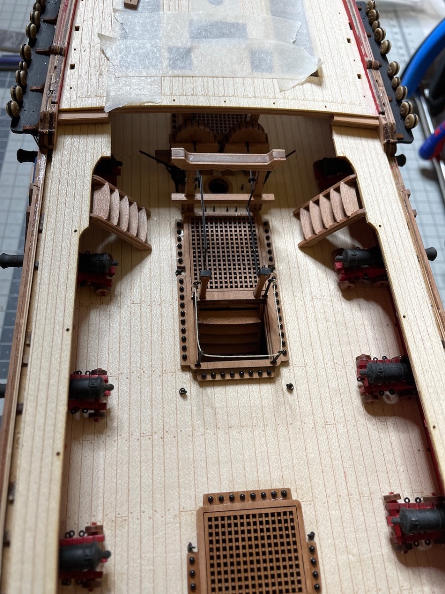
Gangway Stairs and Quarterdeck Gangway Steps construction.
Photo 605-606: Construction of the stairs the same way as the previous ones.
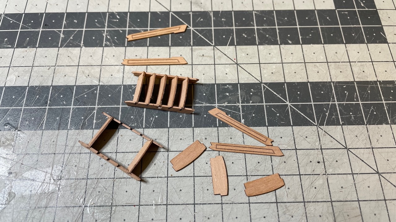
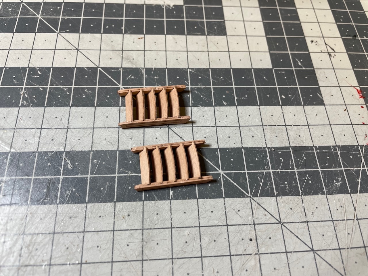
Photo 607: Taking measurements for trimming. I will glue the step on it later, after trimming it to same size with this one. The side resting against the bulwark will need some bewelling.
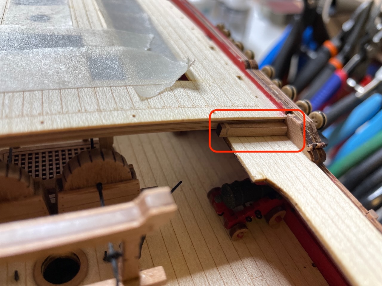
Photo 608: Gangway Stairs and Quarterdeck Gangway Steps in place.

That's all for today. Thanks for watching!
- Prowler901, ccoyle, Knocklouder and 5 others
-
7
-
 1
1
-
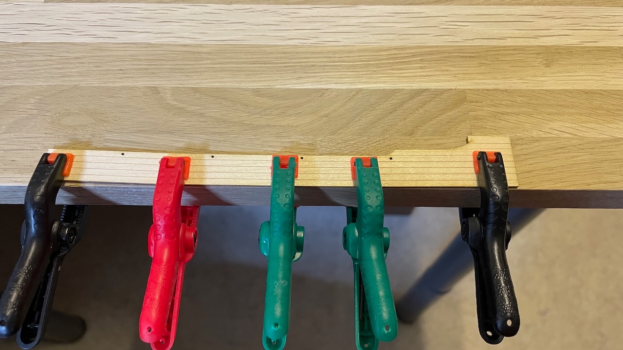
Build Day 58: 3,5 hrs / Total 137 hours
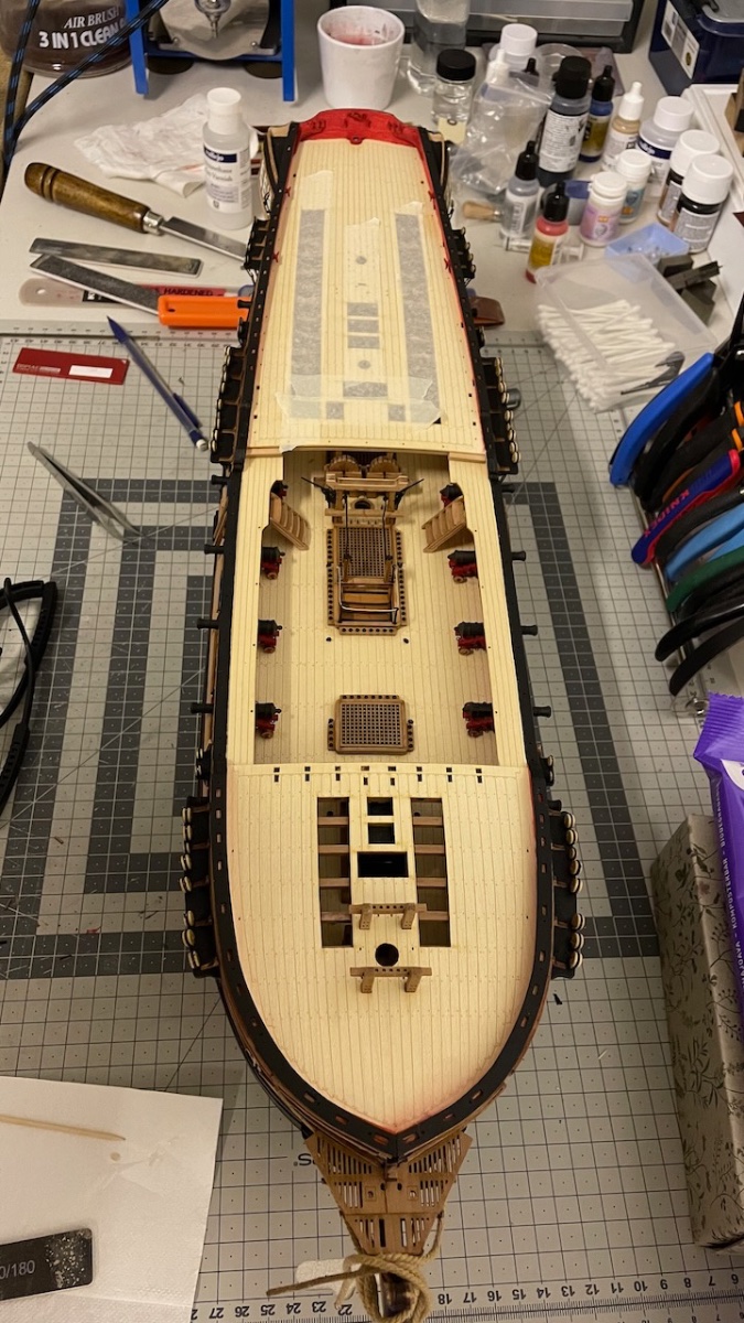
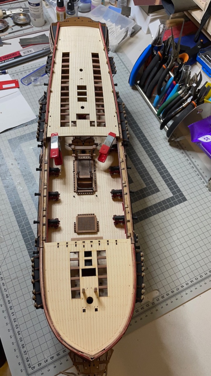
Continued with the Forecastle, Quarter and Gangway deck installation. I am posting a bunch of photos here showing the progress and some details.Overall everything went without surprises and with only slight trims and adjustments.
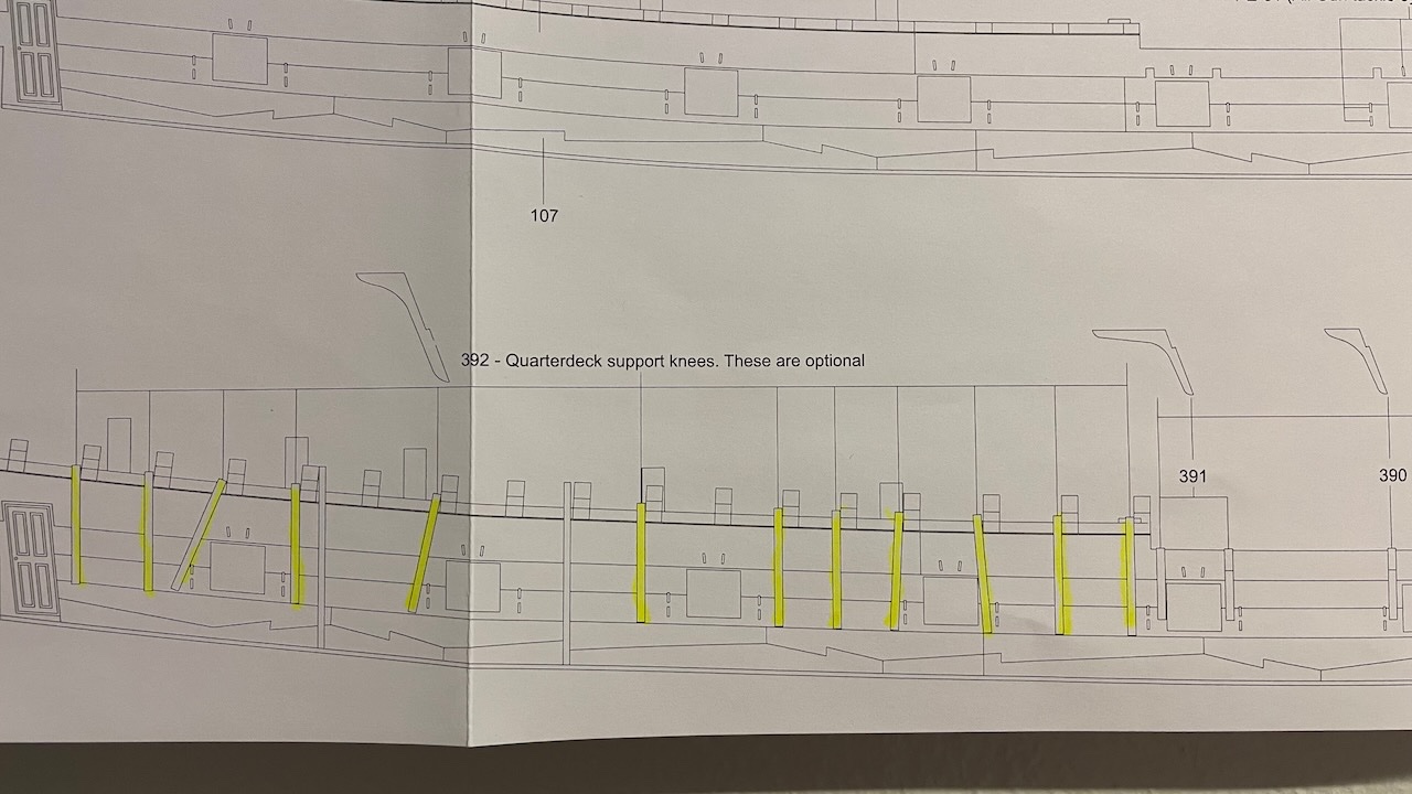
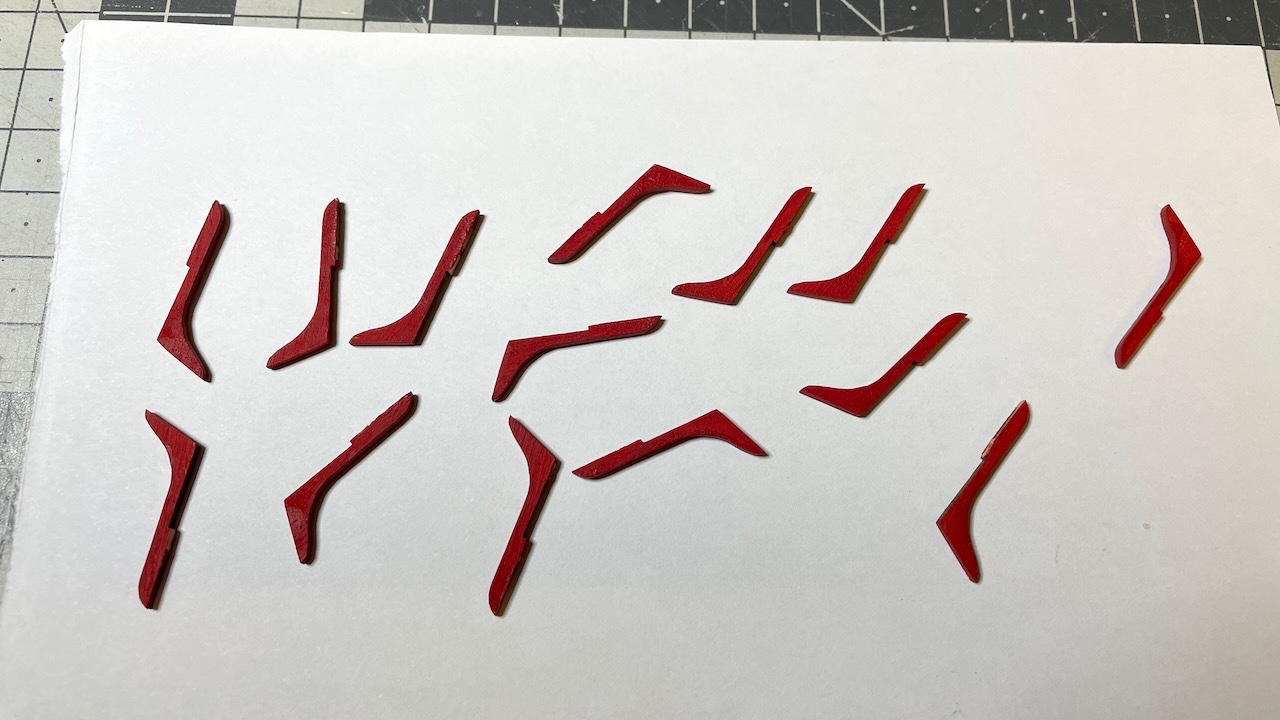
Gangway patterns are composed of two layers glued one on top of another. I clamped them on a piece of wood to prevent from bending while the glue dries. Their installation is a bit tricky to figure out from the photos in the instruction manual however you'll need to follow together with the plans. You'll need to take some measures and trim off parts where it will align with the with the gunwale. For that I would recommend to follow a slightly different order; first gluing the gangway support knees (those red parts) in place and then resting the gangway patterns on them to take the measurements.
Photo 589-604: 16 photos showing the progress:


-
-
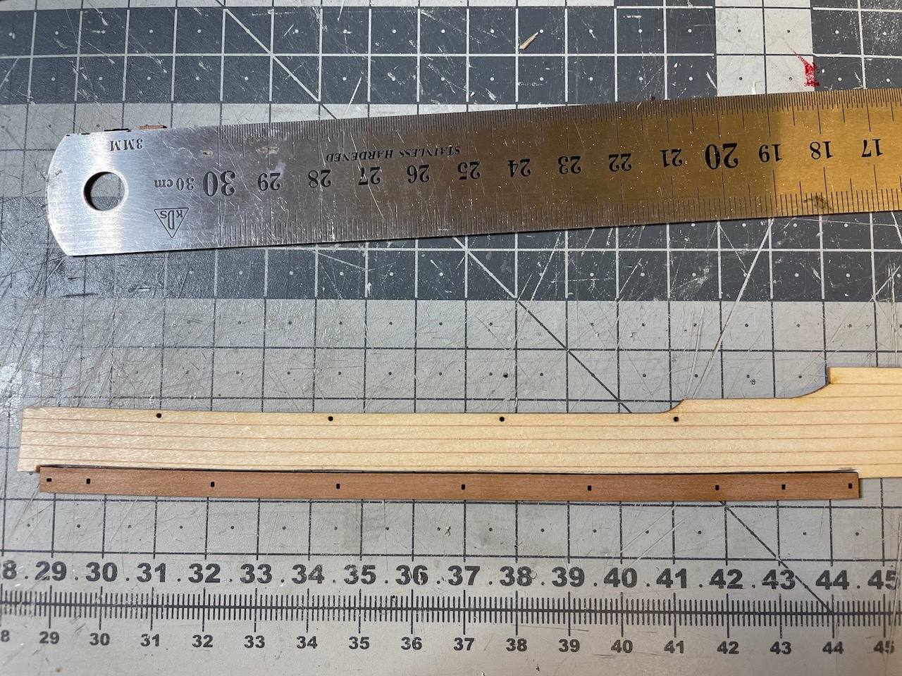
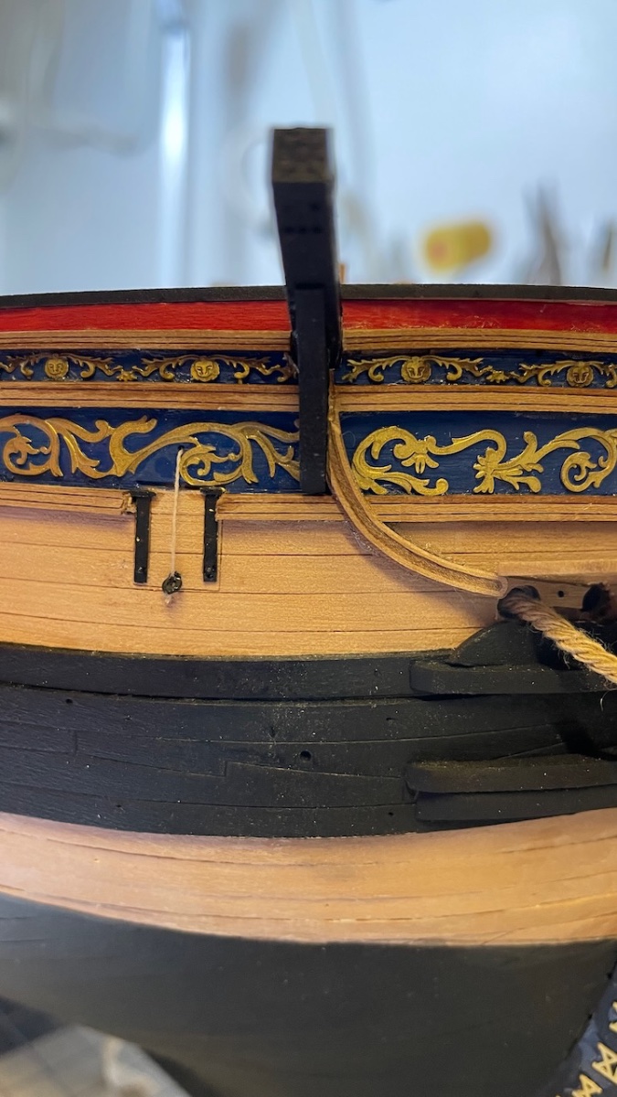
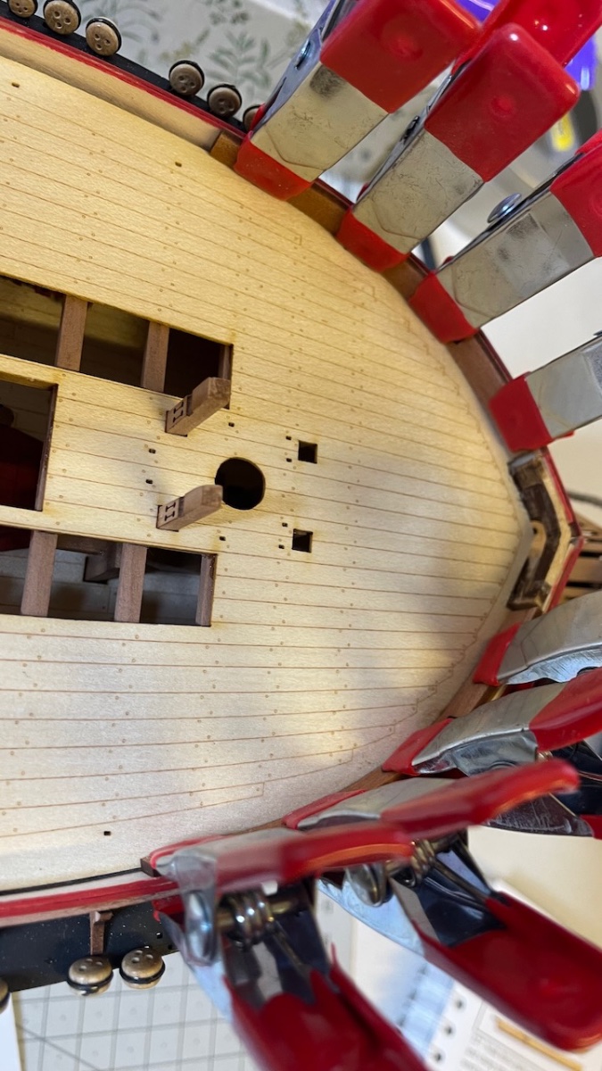
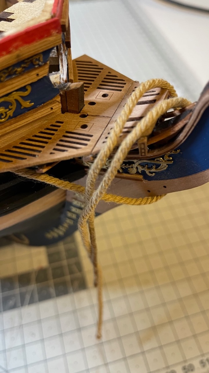
Photos 584-587: Anchor cable (i.e. the thick rope) installation. Hardened a few centimeters with CA glue on one edge help insert through holes easily. They should terminate with a knot behind the bulkhead but I may keep it in one piece just like in the photo. It won't be visible below the deck at all and it may help make adjustments while installing the anchors.


-
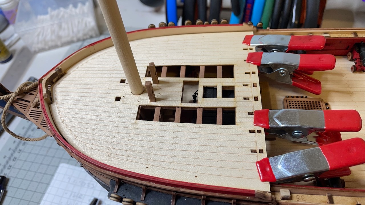
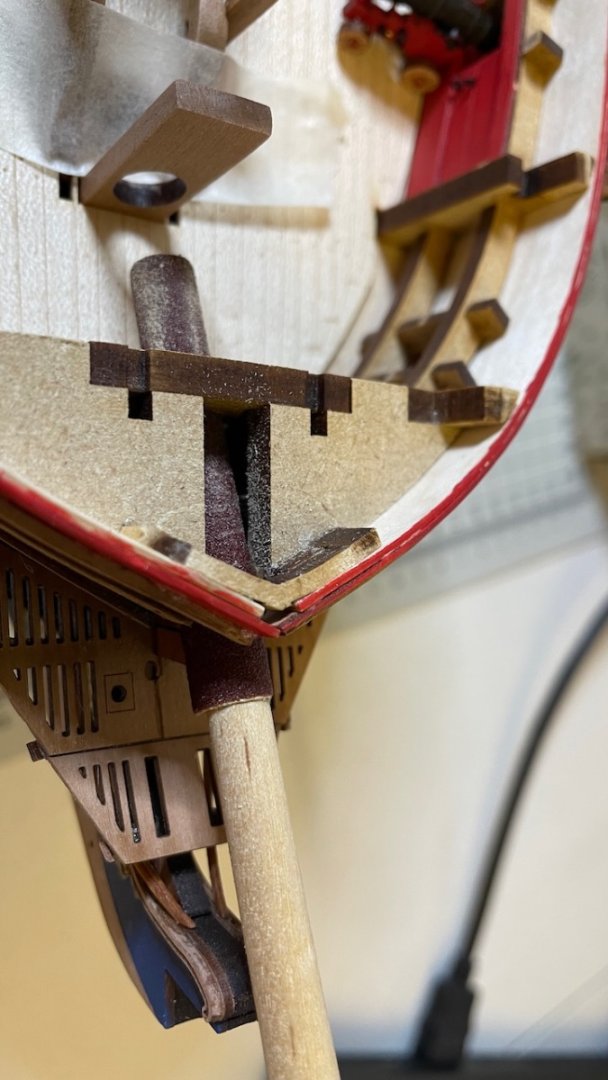
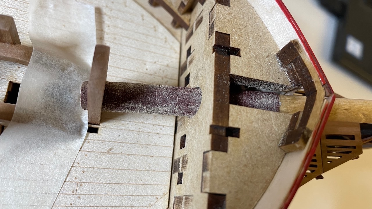
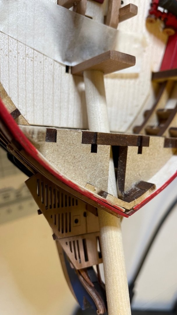
Photo 581-583: Bowsprit opening. I wrapped and glued a thick sandpaper (actually those you use on electric band sanders) around a 6mm dowel and sanded the opening as instructed, including the Bowsprit support on the deck, until my 8mm dowel fits nicely (3rd photo below. Note it is just another 8mm dowel from my stock, not the Sphinx bowel).
- Mr Whippy, Oldsalt1950, Cirdan and 3 others
-
6
-
-
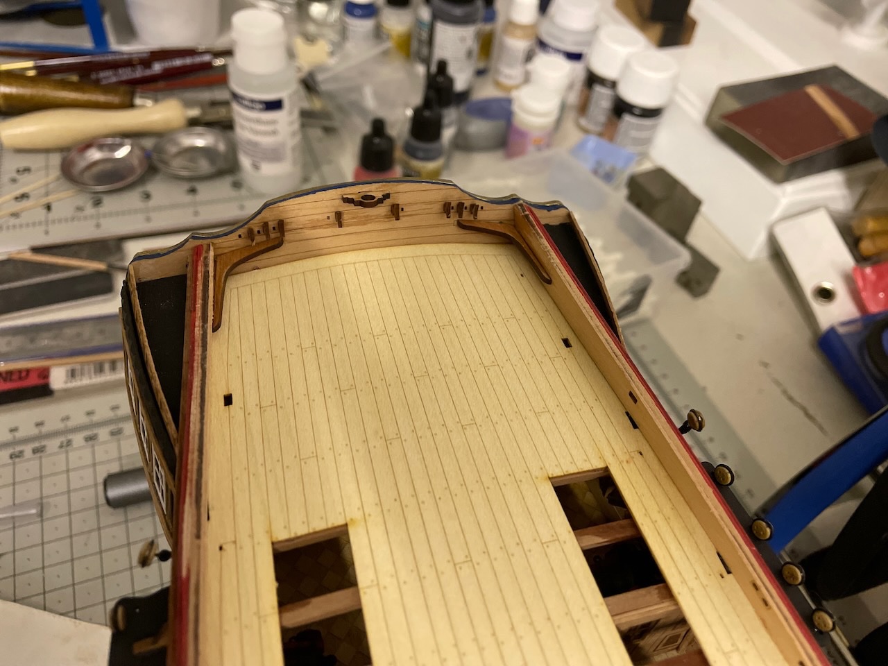
Build Day 57: 4 hrs / Total 133,5 hours
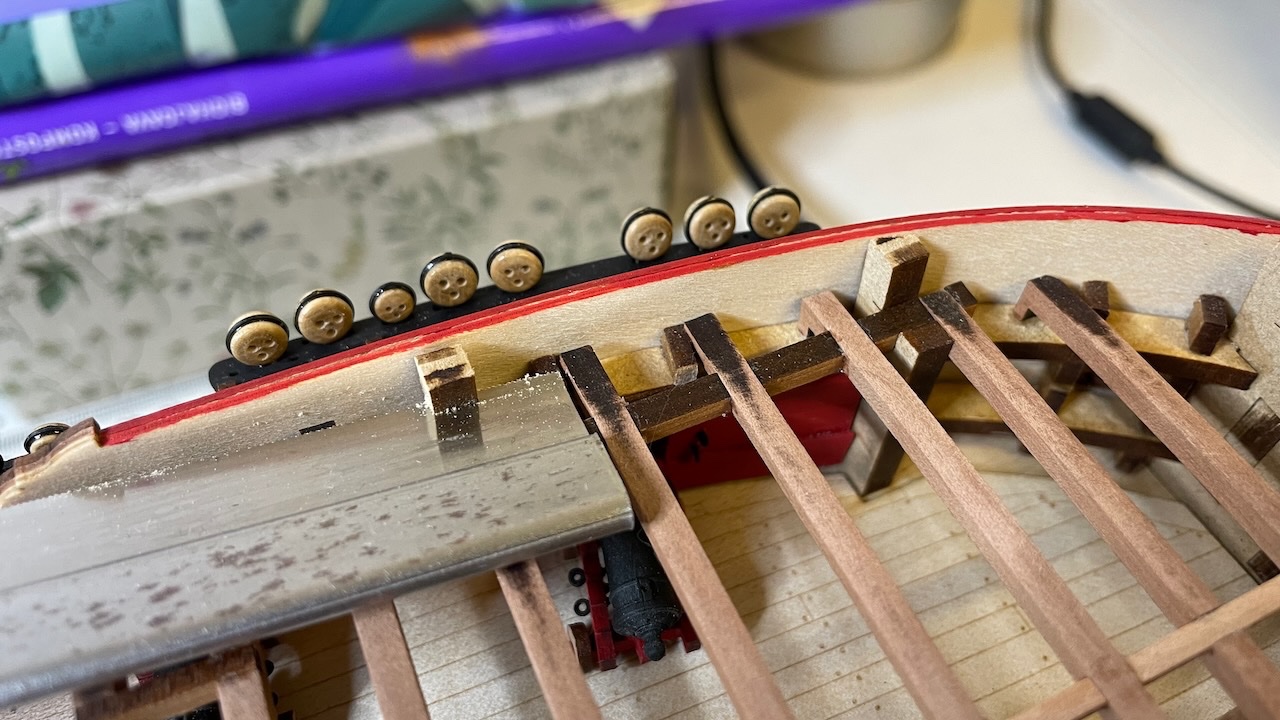
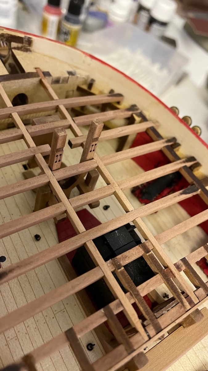
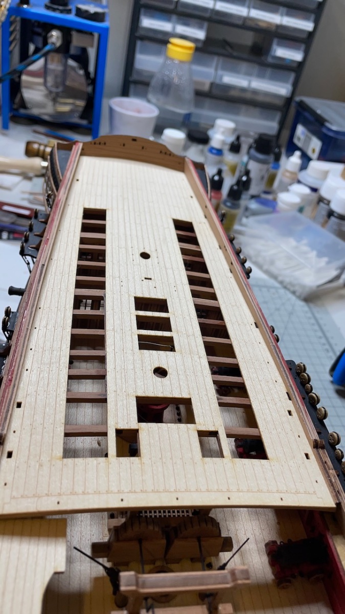
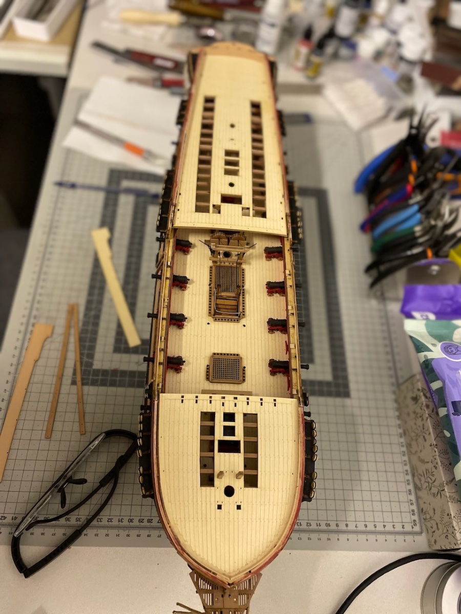
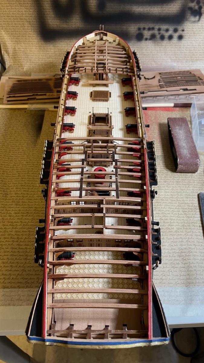
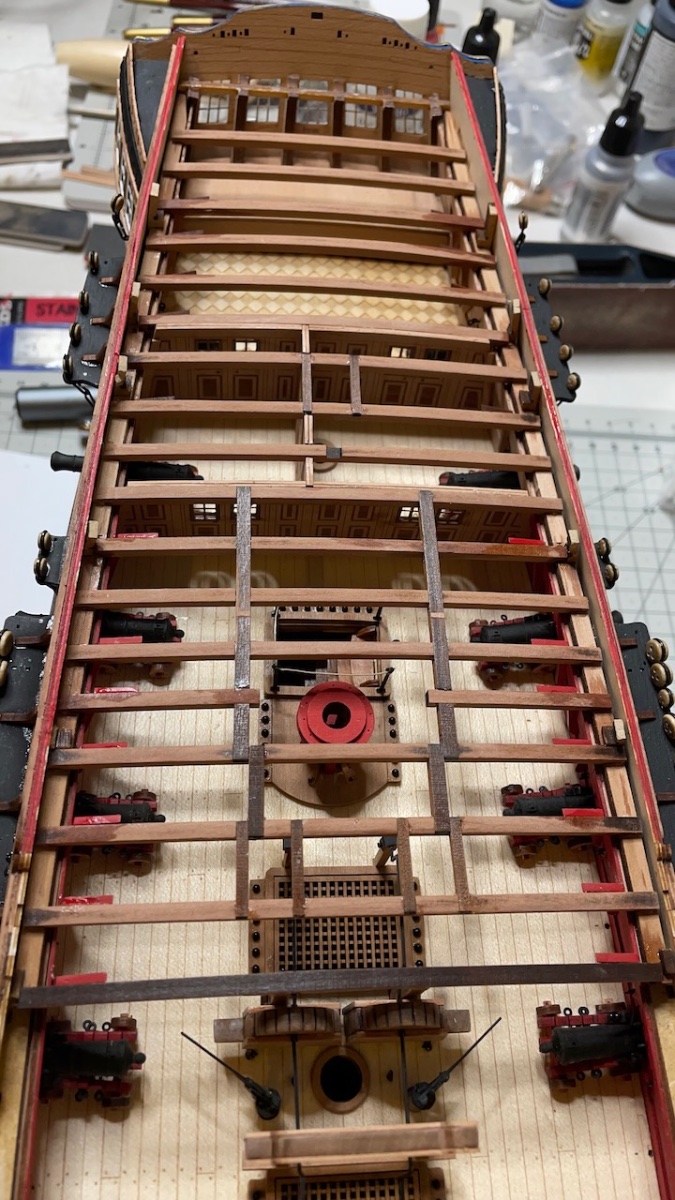
Deck beams. Overall they went without any problems, just minimal sanding and corrections here and there. The way they are designed and is excellent, as in general with this kit.
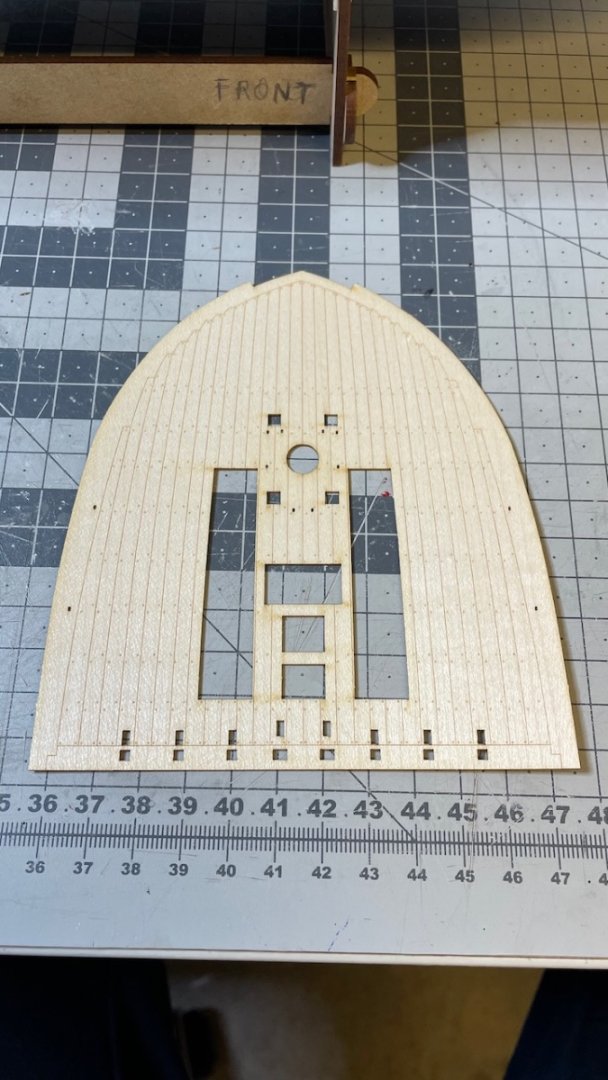
Photo 571: Below the Quarterdeck ones removed and cleaned:
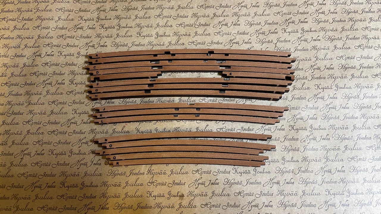
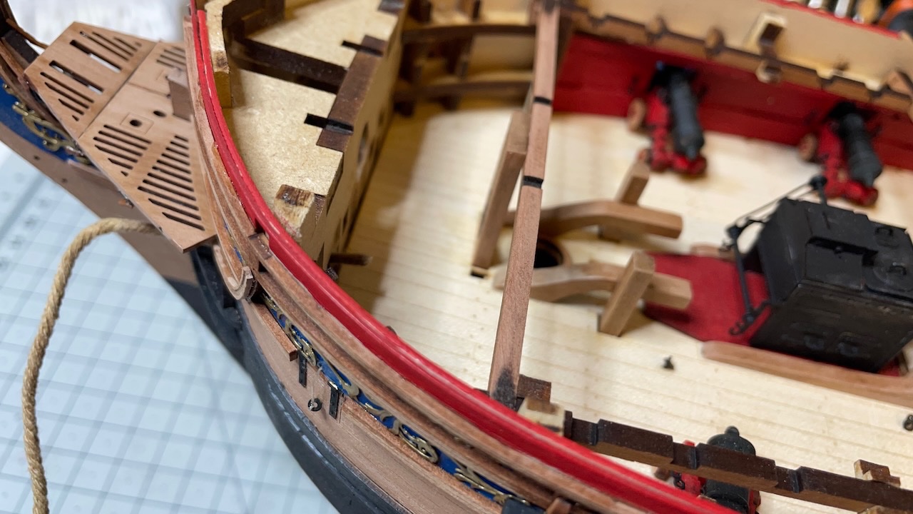
Photo 572: First one to glue sits on top of chain pump handle stanchions, hence it is important to make sure the stanchions have the correct height. I noticed after installing this beam when comparing with the other beams that mine were about 1mm too high, making this one too high to fit the deck sheet later, and I sanded off the beam until the height and curve is flush with rest of the beams.
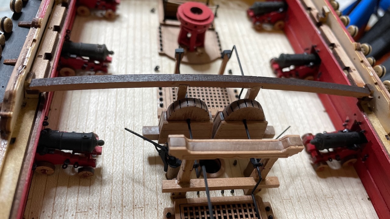
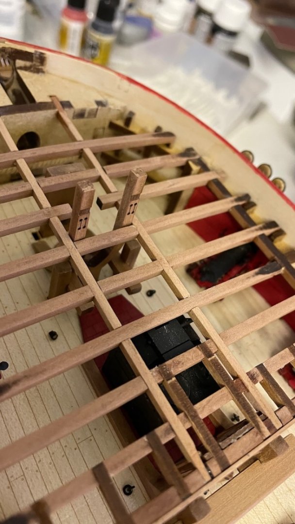
Photo 573: As stated in the instructions, the beams should follow a layout about parallel to the gun deck. It means they should have a slight downward slope towards aft. Without it, the last one won't sit on the bulwark shoulders, as seen in this dry fit photo: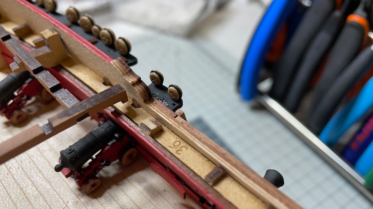
Photo 574: I sanded bulkhead beam slots on both sides as in the picture, in order to give the necessary slope.
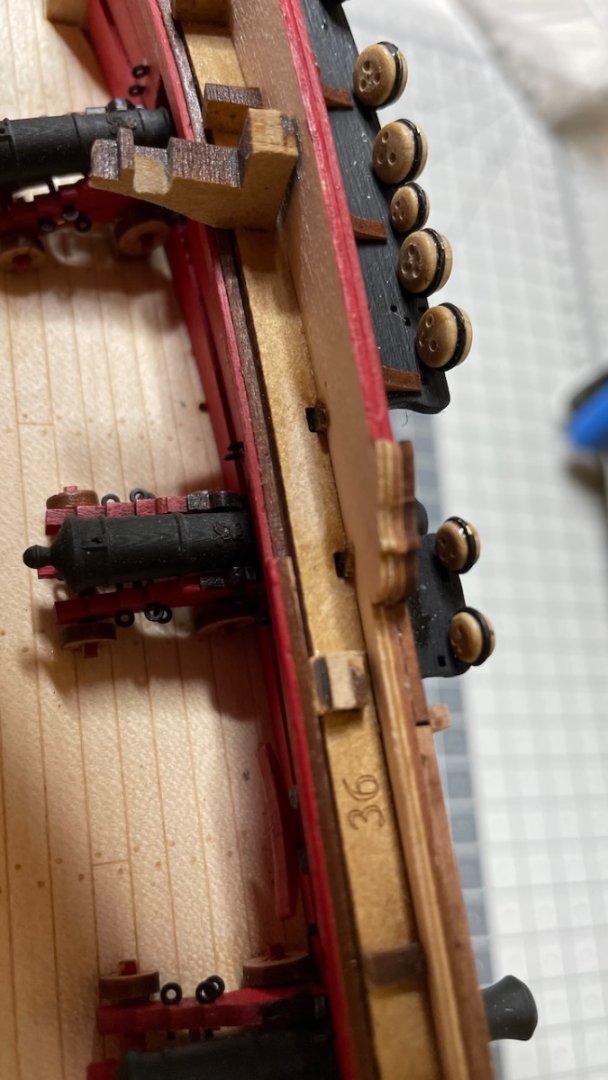
Photo 575: Now they sit properly.
-
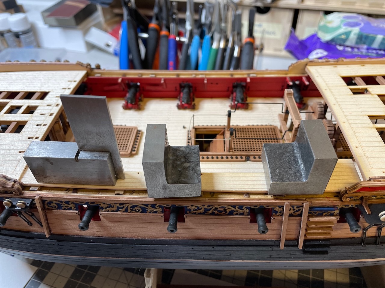
Build Day 56: 3 hrs / Total 129,5 hours
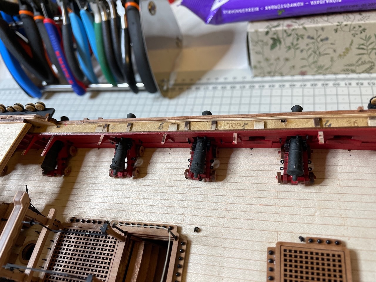
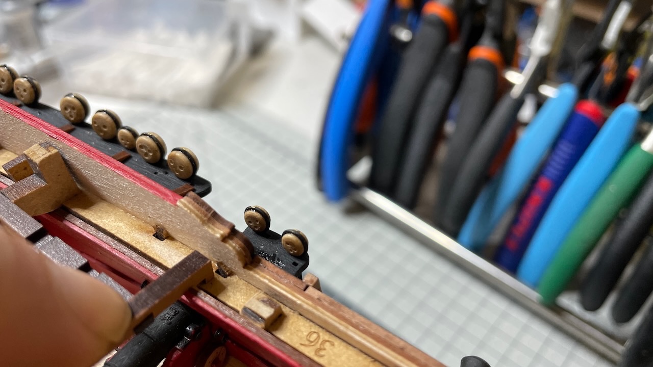
3 hours of work covering the completion of cannon carriages, including gun port painting, which I noticed I forgot to do, almost too late.
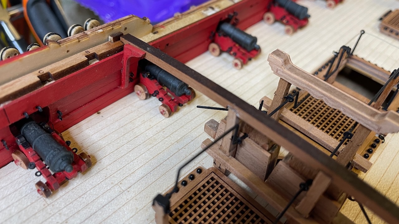
Photo 569: Gun ports painted in red. I should have done it earlier and it was a bit tricky to reach some parts with brush after all the other details around, but I survived.
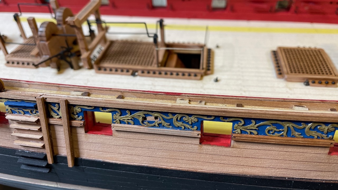
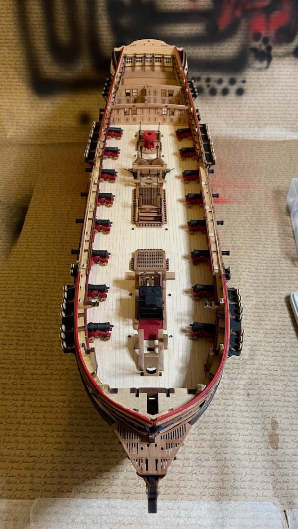
Photo 570: All cannons in place. I decided not to rig them at all. They will be barely visible in the end.
-
-
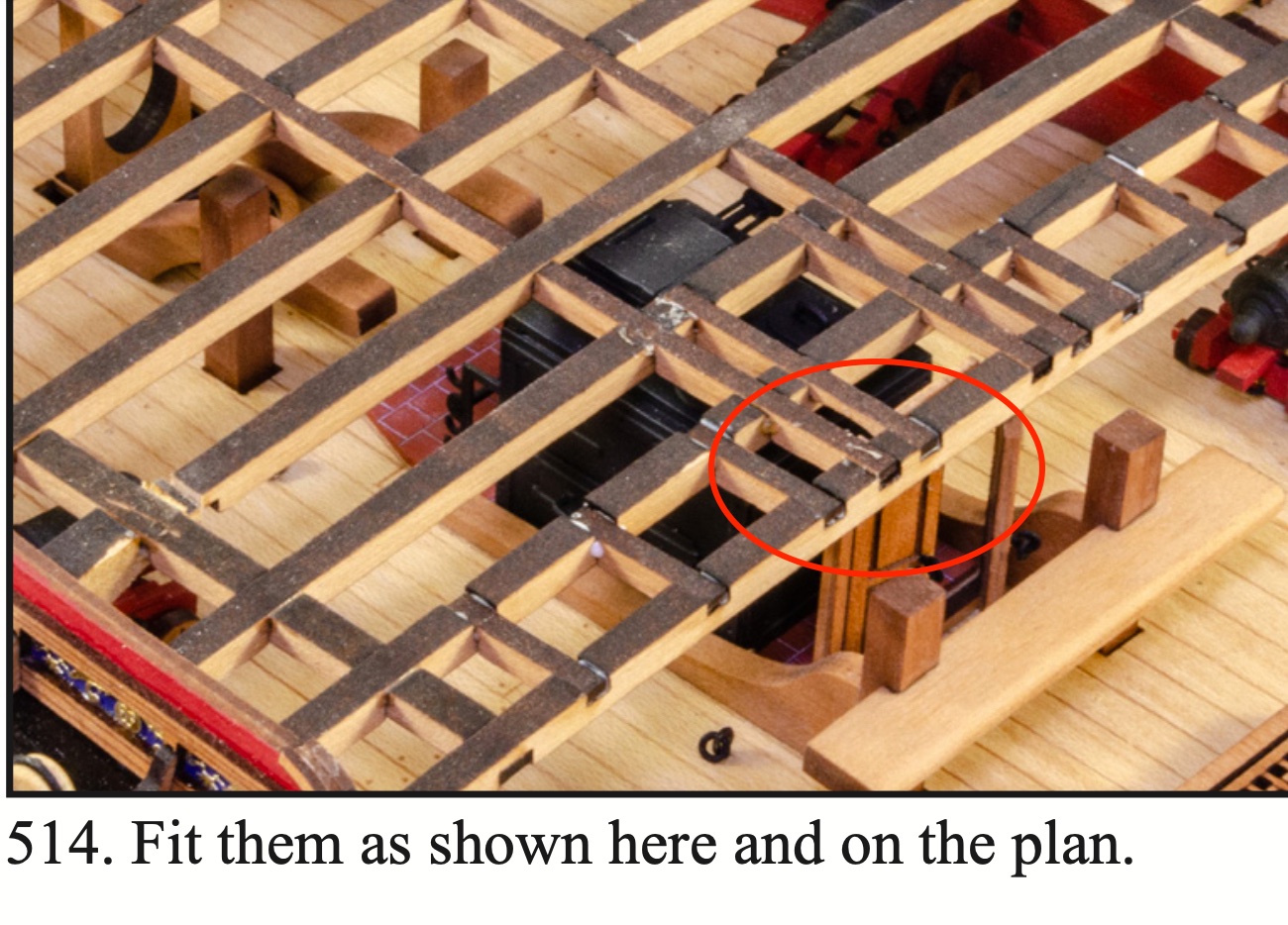
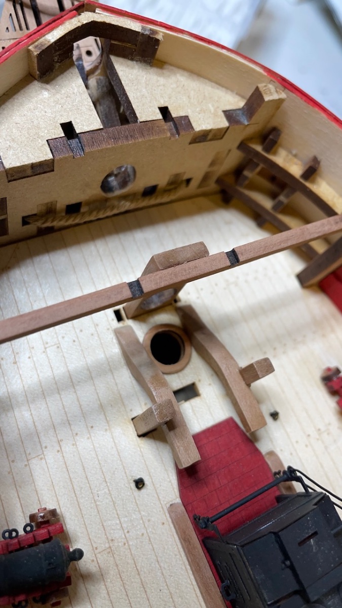
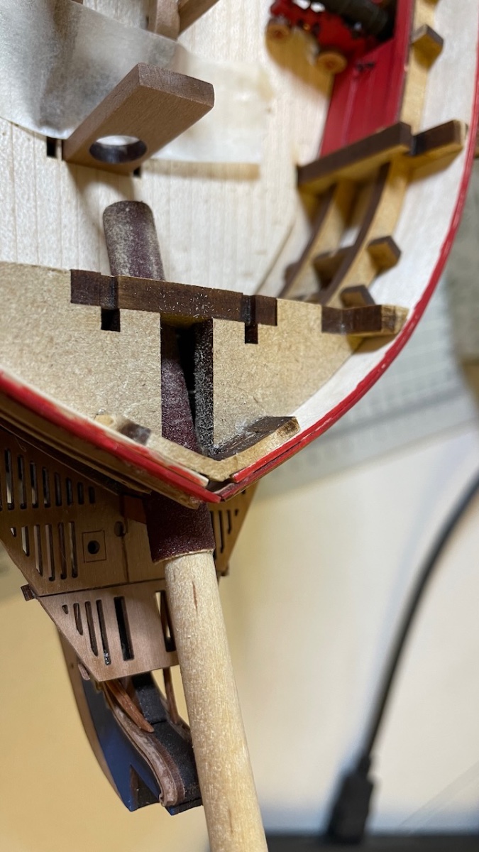
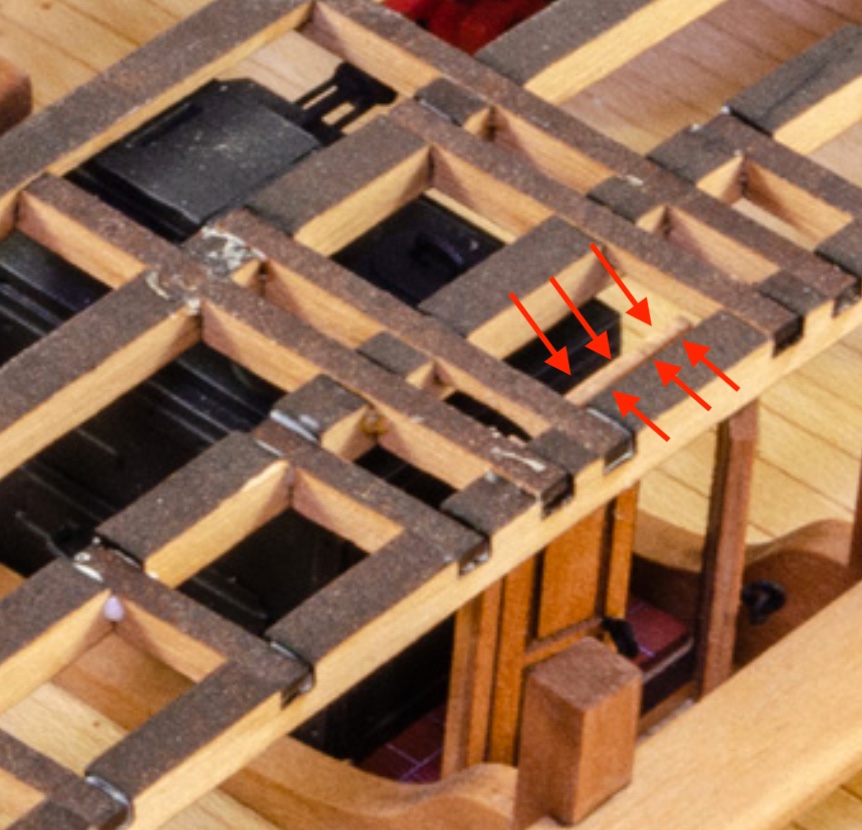
I have proceeded without having time to post my diary, but anyway, I have a question about the deck beam "Z" . In my model it fits right beside the door frame aligning with its grooves. In the manual it somehow looks like it goes over the door. Has it changed since the prototype or am I making a mistake? @James H can you comment? I haven't glued "Z" yet, it is dry fit in the photo.
Photos 567-568 : The picture in the manual vs my build:


HMS Sphinx 1775 by aydingocer - Vanguard Models - 1:64 - Revision #2
in - Kit build logs for subjects built from 1751 - 1800
Posted · Edited by aydingocer
Build Day 66: 3 hours / Total: 155 hours
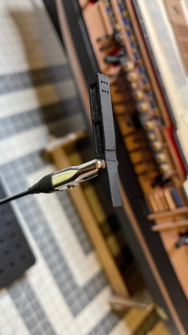
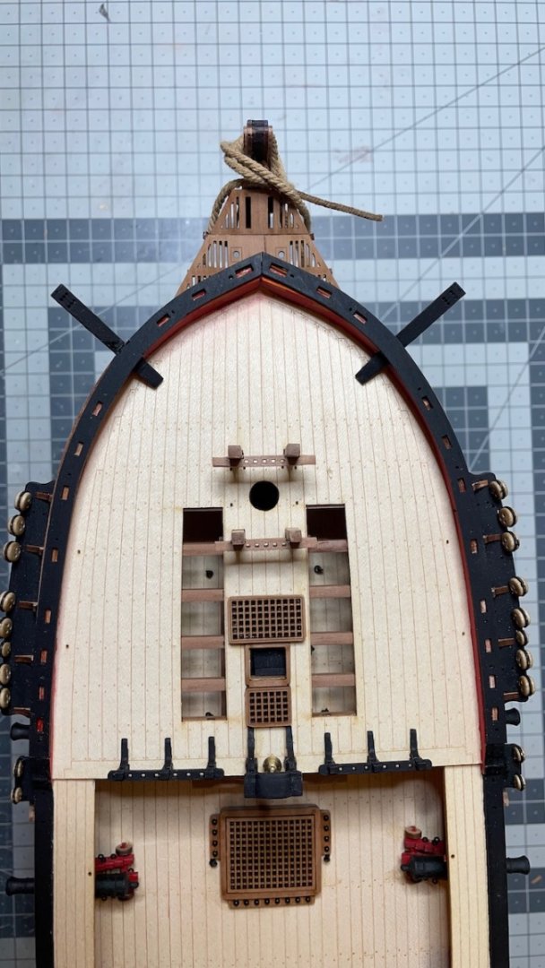
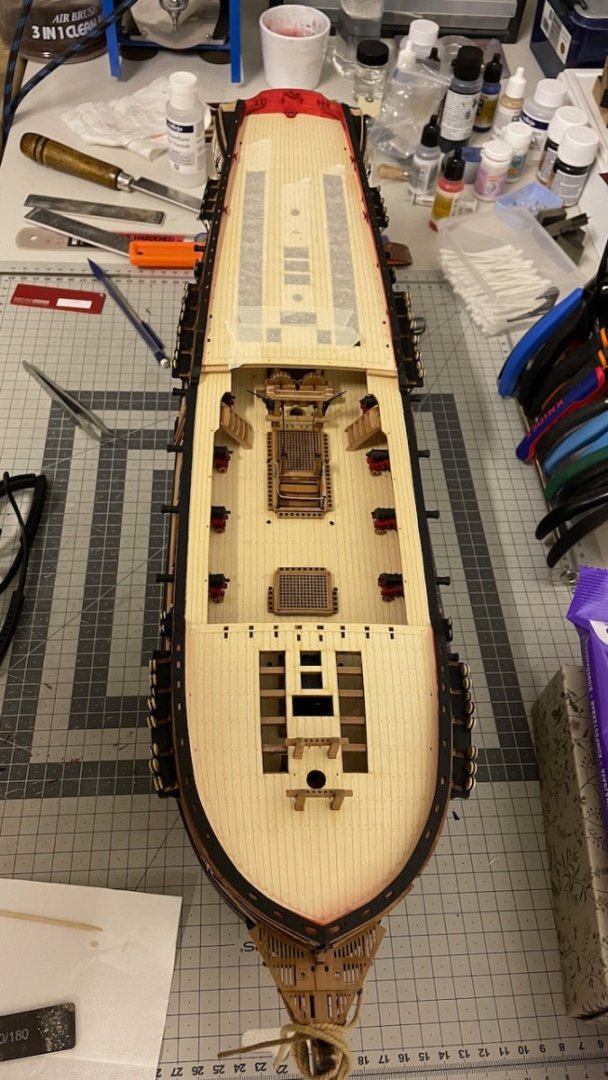
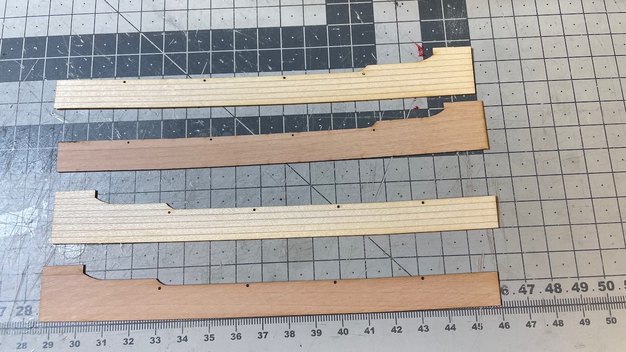
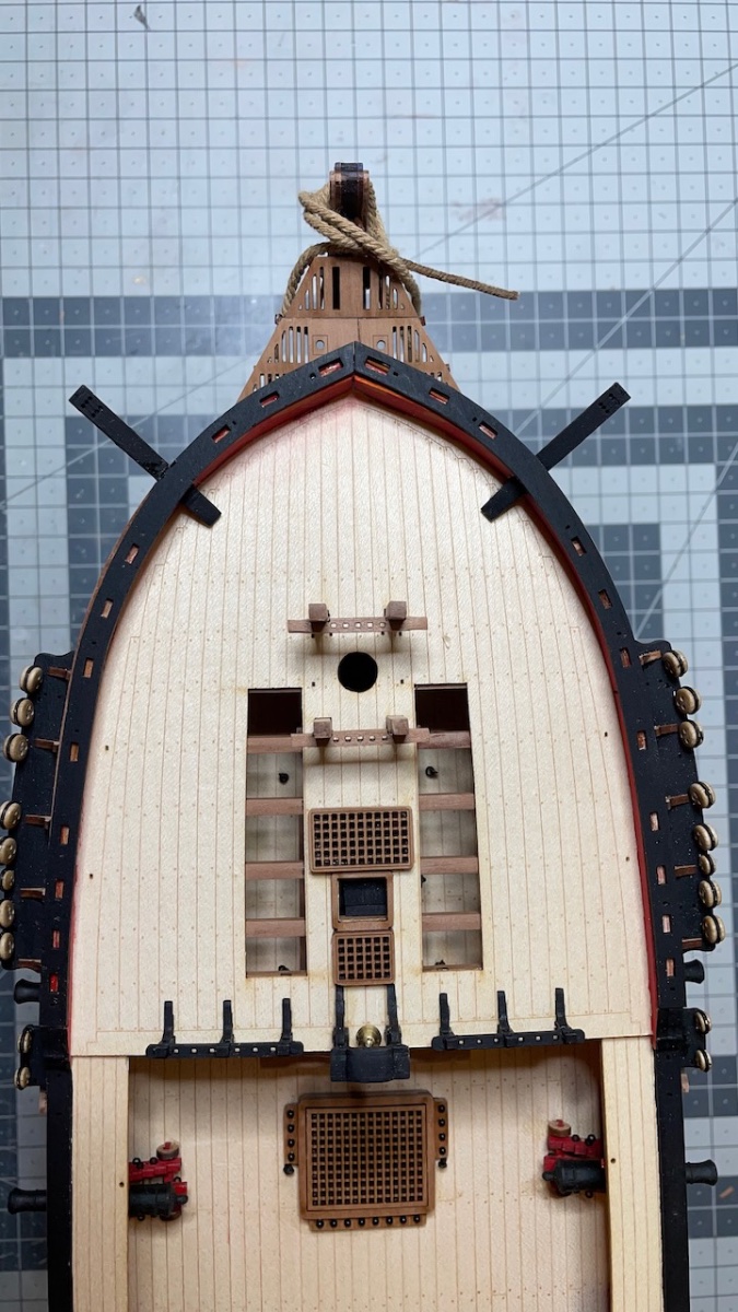
Quarterdeck and Forecastle rail foundations. Below are several photos showing the progress with some notes on my experiences along the way.
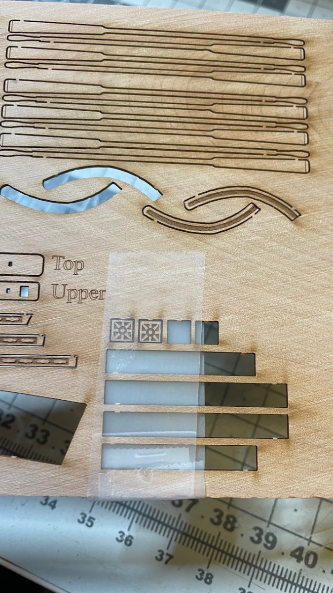
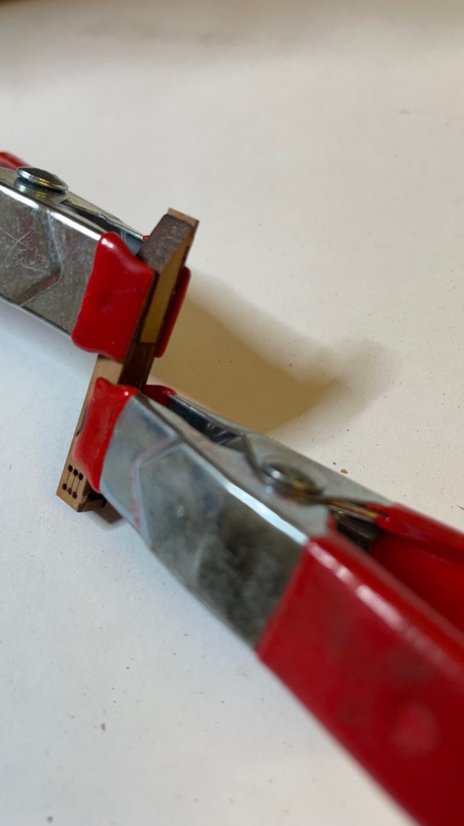
During the construction some steps are skipped in the manual. You'll need refer to the plan throughout the process and this is mentioned in the manual. Also keep the sheet with parts list close to yourself as the rail parts are so similar you can easily lose track of part numbers. I suggest you keep the parts on the wood sheet until you use them.
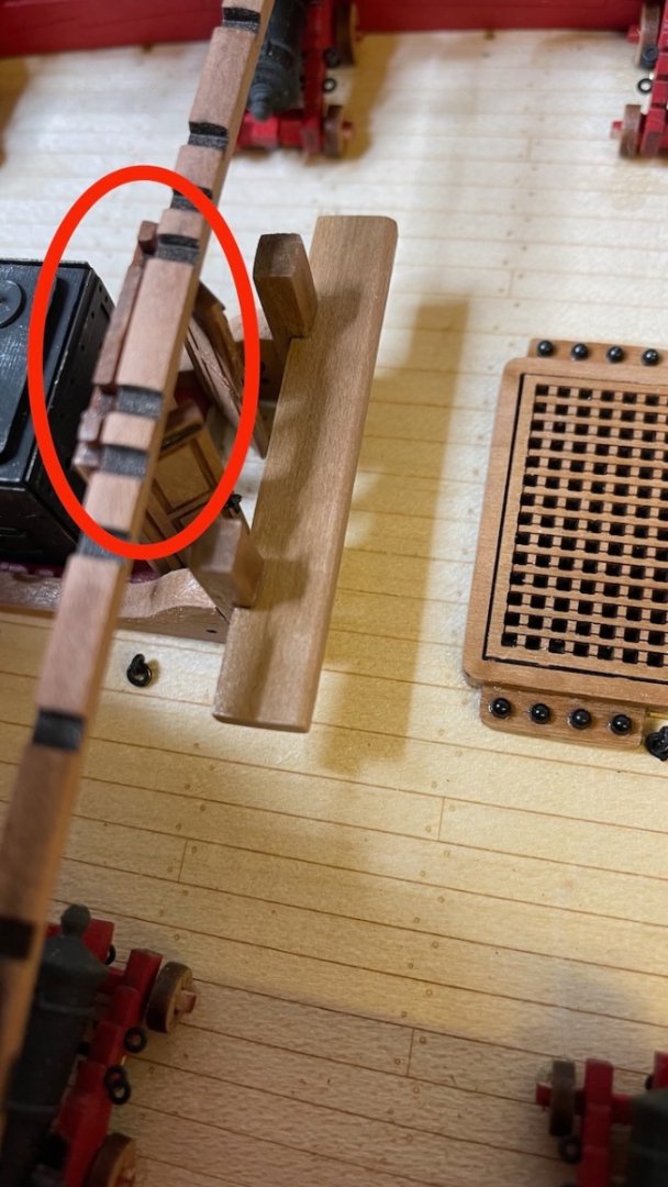
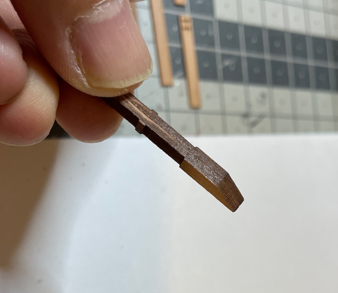
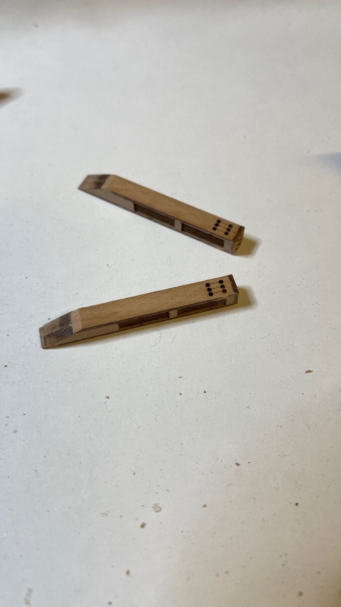
Photo 574: Timberheads top section rounded from the inner and outer sides.
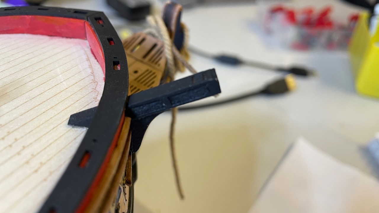
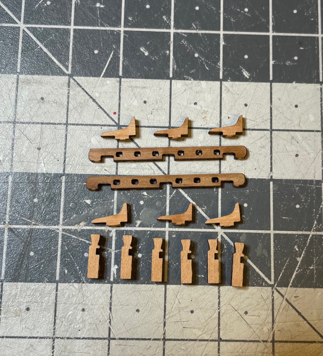
Photos 575-577: One thing not in the instructions but shown in the Plan. Glue parts 102 on either side of 339. Also glue PE-151s in their places.
Photo 578: Similarly glue parts 103 on either side of part 345.
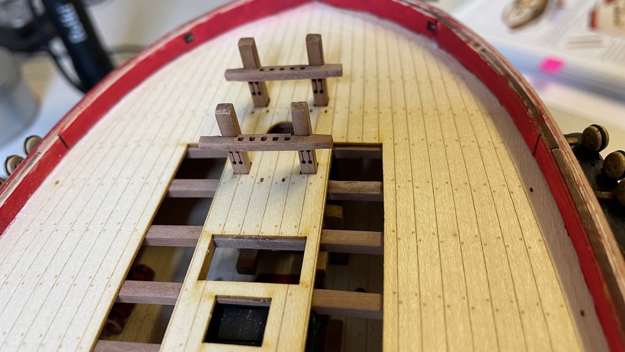
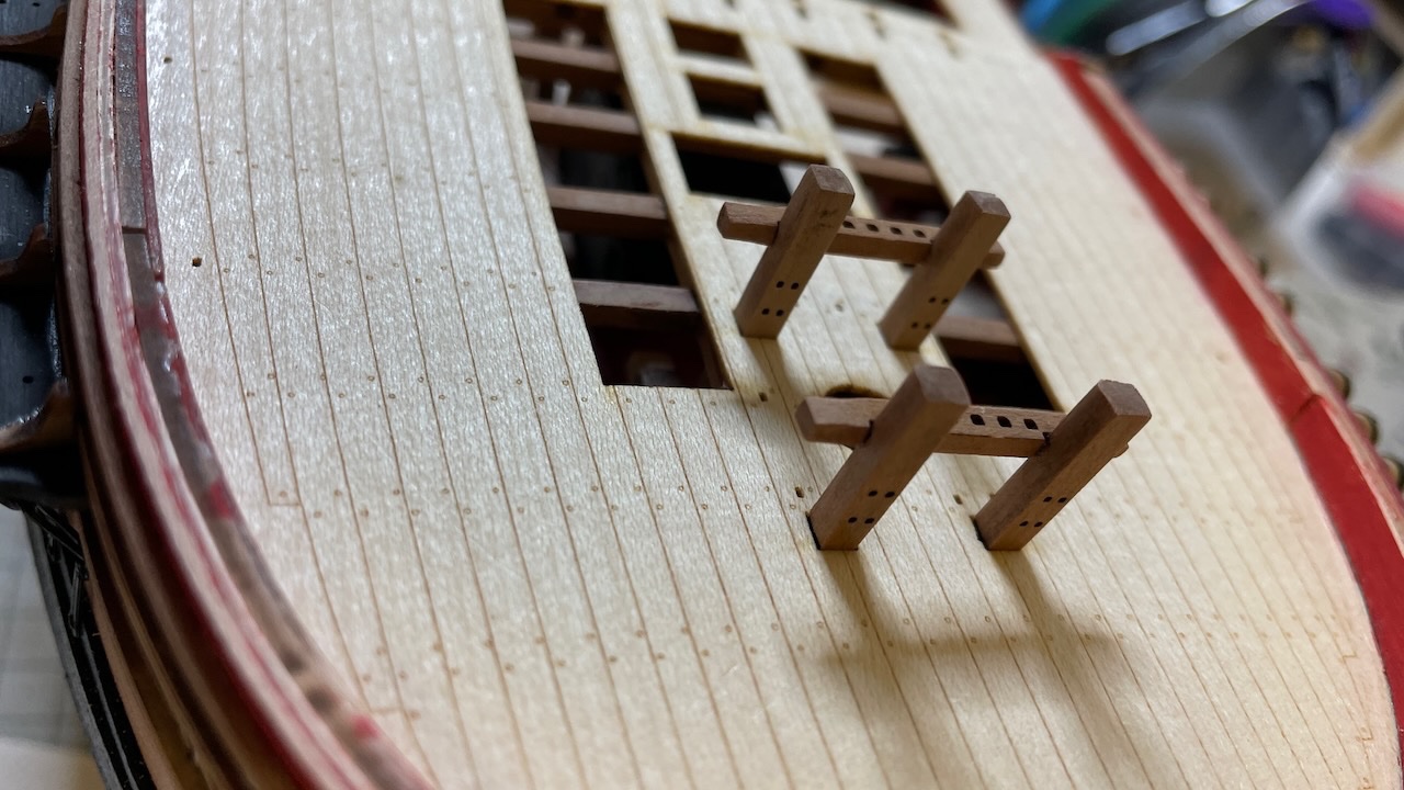
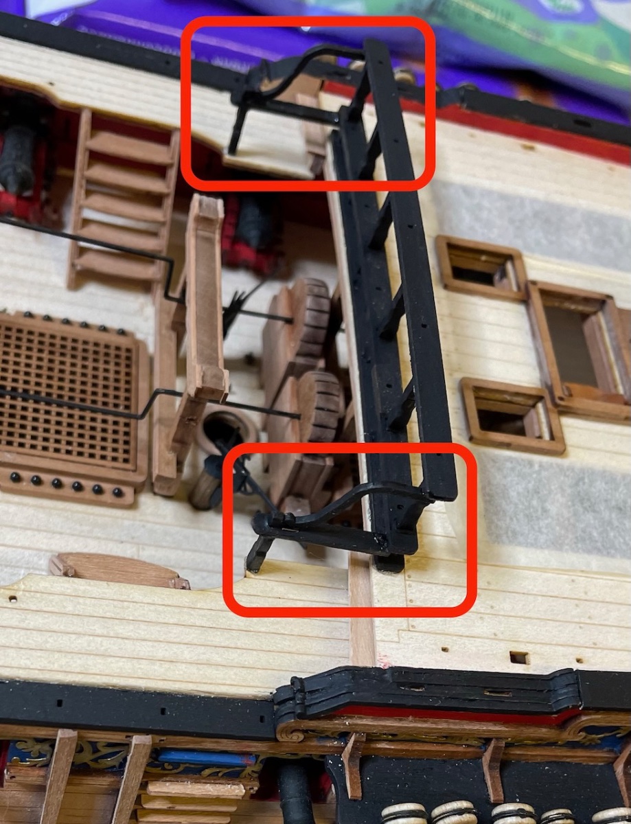
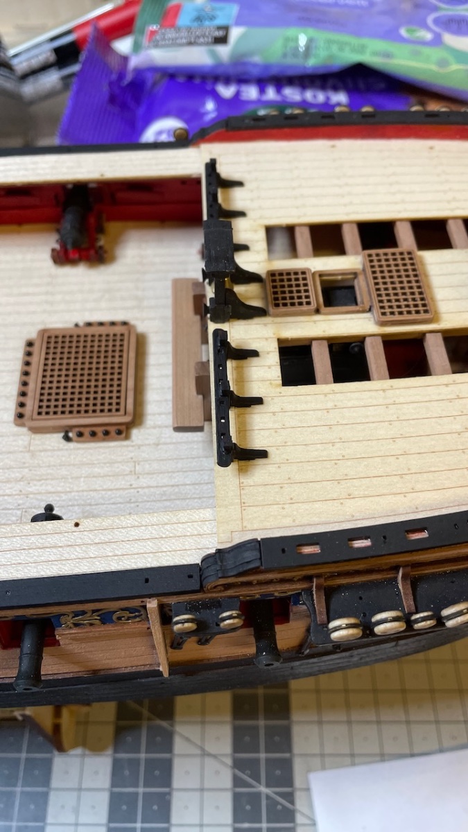
Photos 579-581: All rail elements glued and painted to black.
That's all for today. Thanks for watching!