
Supplies of the Ship Modeler's Handbook are running out. Get your copy NOW before they are gone! Click on photo to order.
×
Chuck
-
Posts
9,447 -
Joined
-
Last visited
Reputation Activity
-

 Chuck got a reaction from Hubac's Historian in How to deal with badly drawn plans?
You cant use auto trace...its just not accurate. It also creates too many nodes in your lines. Unfortunately there are no shortcuts and these "quick-fix" auto functions are just a way to do the job quickly and rather sloppily. The only way you will be able to really do an accurate job is to import the image and trace over it while making corrections yourself. Then as Druxey said, use diagonals and waterlines to fair and correct your traced lines. It is a very time-consuming process but its the only way you will be sure its correct before you start making sawdust.
I usually import an image and scale it to whatever the scale is I am working on...say 1:48. But others find it easier to make the drawing full size so they can use the real measurements from Steele or a builders contract. I use Corel Draw X8. It works great and once you become proficient with using the dozen or so tools and functions needed it goes well. You can use small tricks and methods to speed up the process. I have taught several people over the phone how to use CD and in person. I can usually get them to the point where they can work on their own with good results in just a few hours. But they must understand lofting and fairing and ship design before they start using the software or the lack of architectural knowledge usually does them in. Its easy enough to learn the software....much more difficult and time consuming to learn and understand how draft frames and proof out and fair your lines, along with adding all of those important details not shown on an original draft or simple plan original.
In the image posted above for example, you can see the original draft I will begin drafting and tracing over. Also added to the workspace is an image of a similar contemporary model. This is also scaled up to the same size as the draft. Rather than flip back and forth to a photo on a different file or on paper, having the photo right above my work is an excellent and convenient reference. I can quickly examine the contemporary model for features not shown on the draft or incorporate and design my parts to mimic those on the model. For example, I can quickly use the model to design the joints between the stem and keel to closely mirror that models construction because its right above my workspace and not shown on the draft.
I usually have many more draft copies and photos in my workspace than shown here but this is how I work up a set of plans....once at a pont to fair the frames or correct inaccuracies in the draft I can hide those images while I create my own half-breadth plan or whatever third view I need to prove out my lines. I use waterlines and diagonals to correct my frames while creating my own Half breadth view from the body plan and sheer plan I traced.
Chuck
-
 Chuck got a reaction from Elijah in HMS Atalanta 1775 by tlevine - FINISHED - 1:48 scale - from TFFM plans
Nicely Done Toni....it looks fantastic.....Happy New Year!!
-
 Chuck got a reaction from GuntherMT in How much are you willing to pay
Its really not a fair question. It depends on what you will be satisfied with in the end result. The old motto is true...."you get what you pay for".
You can spend 5 bucks for a chisel or you can spend $150 for a better one. My guess is you will not be happy with the $5 chisel and will end up throwing it away. You can spend $30 for a bandsaw blade or $225. Etc. Etc....
You get what you pay for. This hobby is certainly not going to allow you to build models like this one below for $200 - $300. Its an expensive hobby once it grabs hold of you. It just depends on what you will be satisfied with in the end. Again its not really a fair question because some folks are willing to invest much money (if they can) and much time tobuild a model like this....but many are just as satisfied with a less ambitious result.
If you are going to spend $1000 bucks on something that will take you maybe three years to complete I would say that is a very reasonable and inexpensive hobby. How many people spend just $335 dollars a year on a hobby for decent results. Especially if its something that will give you years of pleasure and enjoyment. I know guys that drop 100's every month bowling on a league......for me its just not worth it. I think that kind of money is better spent on ship modeling is.....so again....its not really a fair question. It more about how much do you really want it. You spend money on what you are passionate about and everyone is different.....I spent 200 dollars on a cheap saw once because I couldnt afford a good one. It was a terrible decision. Finally I saved enough to buy a Byrnes saw and it makes the hobby much more enjoyable. And that saw will last me a lifetime while the cheaper one was good for nothing out of the box.
-
 Chuck got a reaction from mtaylor in How to deal with badly drawn plans?
You cant use auto trace...its just not accurate. It also creates too many nodes in your lines. Unfortunately there are no shortcuts and these "quick-fix" auto functions are just a way to do the job quickly and rather sloppily. The only way you will be able to really do an accurate job is to import the image and trace over it while making corrections yourself. Then as Druxey said, use diagonals and waterlines to fair and correct your traced lines. It is a very time-consuming process but its the only way you will be sure its correct before you start making sawdust.
I usually import an image and scale it to whatever the scale is I am working on...say 1:48. But others find it easier to make the drawing full size so they can use the real measurements from Steele or a builders contract. I use Corel Draw X8. It works great and once you become proficient with using the dozen or so tools and functions needed it goes well. You can use small tricks and methods to speed up the process. I have taught several people over the phone how to use CD and in person. I can usually get them to the point where they can work on their own with good results in just a few hours. But they must understand lofting and fairing and ship design before they start using the software or the lack of architectural knowledge usually does them in. Its easy enough to learn the software....much more difficult and time consuming to learn and understand how draft frames and proof out and fair your lines, along with adding all of those important details not shown on an original draft or simple plan original.
In the image posted above for example, you can see the original draft I will begin drafting and tracing over. Also added to the workspace is an image of a similar contemporary model. This is also scaled up to the same size as the draft. Rather than flip back and forth to a photo on a different file or on paper, having the photo right above my work is an excellent and convenient reference. I can quickly examine the contemporary model for features not shown on the draft or incorporate and design my parts to mimic those on the model. For example, I can quickly use the model to design the joints between the stem and keel to closely mirror that models construction because its right above my workspace and not shown on the draft.
I usually have many more draft copies and photos in my workspace than shown here but this is how I work up a set of plans....once at a pont to fair the frames or correct inaccuracies in the draft I can hide those images while I create my own half-breadth plan or whatever third view I need to prove out my lines. I use waterlines and diagonals to correct my frames while creating my own Half breadth view from the body plan and sheer plan I traced.
Chuck
-
 Chuck reacted to Landlocked123 in Thimbles
Hi Guys,
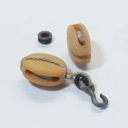
Well I finally got my act together and made some thimbles using Chuck's techniques shown on the the Cheerful build log. Like so many other things in this avocation, it is both easier and harder than it seems.
Once I got the "touch" and made the appropriate sized blunt points to turn the collar it was easy to knock out bunches of them. The smallest thimble is made from Albion 1.5 mm thin walled brass tube. Chuck made the point that this stuff is very soft and easy to cut (there's a link to a video on the Cheerful log). This actually gave me more trouble than any other aspect of making these. I knew I was working with metal and it took a long time before I found out just how much of a soft touch it took. I was using so much pressure that not only did I cut the tube, but I scored the brass rod I had inserted into the tube. With the K&S I had on hand, I didn't have much luck rolling against the exacto blade, so I used a jeweler's saw to cut the blanks.
I made two blunt points of different sizes to roll the collars out of some steel common nails. I cut off the heads, chucked them into my drill press, used a file to create a rounded cone, and polished with some sand paper. A few light taps on the mandrel and done.
Best,
John
Ps. This was my first shot at seizing the eyes and I used some some of #8 synthetic fly tying thread. Neither CA or diluted PVA would stick to it and the clove hitches I used wouldn't hold. Next time around I used some #8 Unithread.....much better. J.
-
 Chuck got a reaction from Dubz in How to deal with badly drawn plans?
You cant use auto trace...its just not accurate. It also creates too many nodes in your lines. Unfortunately there are no shortcuts and these "quick-fix" auto functions are just a way to do the job quickly and rather sloppily. The only way you will be able to really do an accurate job is to import the image and trace over it while making corrections yourself. Then as Druxey said, use diagonals and waterlines to fair and correct your traced lines. It is a very time-consuming process but its the only way you will be sure its correct before you start making sawdust.
I usually import an image and scale it to whatever the scale is I am working on...say 1:48. But others find it easier to make the drawing full size so they can use the real measurements from Steele or a builders contract. I use Corel Draw X8. It works great and once you become proficient with using the dozen or so tools and functions needed it goes well. You can use small tricks and methods to speed up the process. I have taught several people over the phone how to use CD and in person. I can usually get them to the point where they can work on their own with good results in just a few hours. But they must understand lofting and fairing and ship design before they start using the software or the lack of architectural knowledge usually does them in. Its easy enough to learn the software....much more difficult and time consuming to learn and understand how draft frames and proof out and fair your lines, along with adding all of those important details not shown on an original draft or simple plan original.
In the image posted above for example, you can see the original draft I will begin drafting and tracing over. Also added to the workspace is an image of a similar contemporary model. This is also scaled up to the same size as the draft. Rather than flip back and forth to a photo on a different file or on paper, having the photo right above my work is an excellent and convenient reference. I can quickly examine the contemporary model for features not shown on the draft or incorporate and design my parts to mimic those on the model. For example, I can quickly use the model to design the joints between the stem and keel to closely mirror that models construction because its right above my workspace and not shown on the draft.
I usually have many more draft copies and photos in my workspace than shown here but this is how I work up a set of plans....once at a pont to fair the frames or correct inaccuracies in the draft I can hide those images while I create my own half-breadth plan or whatever third view I need to prove out my lines. I use waterlines and diagonals to correct my frames while creating my own Half breadth view from the body plan and sheer plan I traced.
Chuck
-
 Chuck got a reaction from Nirvana in USF Confederacy by Augie & Moonbug - FINISHED - Model Shipways - 1:64
Thats a lot port lids....way more than are needed. Remember that not every port gets a lid. Only 7 per side.
Chuck
-
 Chuck got a reaction from Mark P in How to deal with badly drawn plans?
You cant use auto trace...its just not accurate. It also creates too many nodes in your lines. Unfortunately there are no shortcuts and these "quick-fix" auto functions are just a way to do the job quickly and rather sloppily. The only way you will be able to really do an accurate job is to import the image and trace over it while making corrections yourself. Then as Druxey said, use diagonals and waterlines to fair and correct your traced lines. It is a very time-consuming process but its the only way you will be sure its correct before you start making sawdust.
I usually import an image and scale it to whatever the scale is I am working on...say 1:48. But others find it easier to make the drawing full size so they can use the real measurements from Steele or a builders contract. I use Corel Draw X8. It works great and once you become proficient with using the dozen or so tools and functions needed it goes well. You can use small tricks and methods to speed up the process. I have taught several people over the phone how to use CD and in person. I can usually get them to the point where they can work on their own with good results in just a few hours. But they must understand lofting and fairing and ship design before they start using the software or the lack of architectural knowledge usually does them in. Its easy enough to learn the software....much more difficult and time consuming to learn and understand how draft frames and proof out and fair your lines, along with adding all of those important details not shown on an original draft or simple plan original.
In the image posted above for example, you can see the original draft I will begin drafting and tracing over. Also added to the workspace is an image of a similar contemporary model. This is also scaled up to the same size as the draft. Rather than flip back and forth to a photo on a different file or on paper, having the photo right above my work is an excellent and convenient reference. I can quickly examine the contemporary model for features not shown on the draft or incorporate and design my parts to mimic those on the model. For example, I can quickly use the model to design the joints between the stem and keel to closely mirror that models construction because its right above my workspace and not shown on the draft.
I usually have many more draft copies and photos in my workspace than shown here but this is how I work up a set of plans....once at a pont to fair the frames or correct inaccuracies in the draft I can hide those images while I create my own half-breadth plan or whatever third view I need to prove out my lines. I use waterlines and diagonals to correct my frames while creating my own Half breadth view from the body plan and sheer plan I traced.
Chuck
-
 Chuck got a reaction from russ in How to deal with badly drawn plans?
You cant use auto trace...its just not accurate. It also creates too many nodes in your lines. Unfortunately there are no shortcuts and these "quick-fix" auto functions are just a way to do the job quickly and rather sloppily. The only way you will be able to really do an accurate job is to import the image and trace over it while making corrections yourself. Then as Druxey said, use diagonals and waterlines to fair and correct your traced lines. It is a very time-consuming process but its the only way you will be sure its correct before you start making sawdust.
I usually import an image and scale it to whatever the scale is I am working on...say 1:48. But others find it easier to make the drawing full size so they can use the real measurements from Steele or a builders contract. I use Corel Draw X8. It works great and once you become proficient with using the dozen or so tools and functions needed it goes well. You can use small tricks and methods to speed up the process. I have taught several people over the phone how to use CD and in person. I can usually get them to the point where they can work on their own with good results in just a few hours. But they must understand lofting and fairing and ship design before they start using the software or the lack of architectural knowledge usually does them in. Its easy enough to learn the software....much more difficult and time consuming to learn and understand how draft frames and proof out and fair your lines, along with adding all of those important details not shown on an original draft or simple plan original.
In the image posted above for example, you can see the original draft I will begin drafting and tracing over. Also added to the workspace is an image of a similar contemporary model. This is also scaled up to the same size as the draft. Rather than flip back and forth to a photo on a different file or on paper, having the photo right above my work is an excellent and convenient reference. I can quickly examine the contemporary model for features not shown on the draft or incorporate and design my parts to mimic those on the model. For example, I can quickly use the model to design the joints between the stem and keel to closely mirror that models construction because its right above my workspace and not shown on the draft.
I usually have many more draft copies and photos in my workspace than shown here but this is how I work up a set of plans....once at a pont to fair the frames or correct inaccuracies in the draft I can hide those images while I create my own half-breadth plan or whatever third view I need to prove out my lines. I use waterlines and diagonals to correct my frames while creating my own Half breadth view from the body plan and sheer plan I traced.
Chuck
-
 Chuck got a reaction from -Dallen in How to deal with badly drawn plans?
You cant use auto trace...its just not accurate. It also creates too many nodes in your lines. Unfortunately there are no shortcuts and these "quick-fix" auto functions are just a way to do the job quickly and rather sloppily. The only way you will be able to really do an accurate job is to import the image and trace over it while making corrections yourself. Then as Druxey said, use diagonals and waterlines to fair and correct your traced lines. It is a very time-consuming process but its the only way you will be sure its correct before you start making sawdust.
I usually import an image and scale it to whatever the scale is I am working on...say 1:48. But others find it easier to make the drawing full size so they can use the real measurements from Steele or a builders contract. I use Corel Draw X8. It works great and once you become proficient with using the dozen or so tools and functions needed it goes well. You can use small tricks and methods to speed up the process. I have taught several people over the phone how to use CD and in person. I can usually get them to the point where they can work on their own with good results in just a few hours. But they must understand lofting and fairing and ship design before they start using the software or the lack of architectural knowledge usually does them in. Its easy enough to learn the software....much more difficult and time consuming to learn and understand how draft frames and proof out and fair your lines, along with adding all of those important details not shown on an original draft or simple plan original.
In the image posted above for example, you can see the original draft I will begin drafting and tracing over. Also added to the workspace is an image of a similar contemporary model. This is also scaled up to the same size as the draft. Rather than flip back and forth to a photo on a different file or on paper, having the photo right above my work is an excellent and convenient reference. I can quickly examine the contemporary model for features not shown on the draft or incorporate and design my parts to mimic those on the model. For example, I can quickly use the model to design the joints between the stem and keel to closely mirror that models construction because its right above my workspace and not shown on the draft.
I usually have many more draft copies and photos in my workspace than shown here but this is how I work up a set of plans....once at a pont to fair the frames or correct inaccuracies in the draft I can hide those images while I create my own half-breadth plan or whatever third view I need to prove out my lines. I use waterlines and diagonals to correct my frames while creating my own Half breadth view from the body plan and sheer plan I traced.
Chuck
-
 Chuck got a reaction from Moonbug in USF Confederacy by Augie & Moonbug - FINISHED - Model Shipways - 1:64
Thats a lot port lids....way more than are needed. Remember that not every port gets a lid. Only 7 per side.
Chuck
-
Chuck reacted to Geoff Matson in Constitution by Geoff Matson - Model Shipways 2040 - 1/76 scale
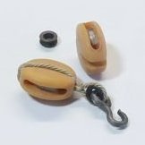
I needed to make some thimbles for my mast slings. I remembered Chuck showed how to do it in one of build logs. His way made making them simple. I used 16th inch K&S brass tubing. It was scored with the #11 x-acto knife and simply rolled back and forth with the x-acto knife, until it cut through the tubing. It sounds too simple, but it worked without much of a learning curve. Once cut, I used a punch made from an old nail and flared both ends. The flares will allow the line to be wrapped around the thimble and keep the line in grove created by the flare. After making a bunch they were blacked using Birchwood Casey Brass Black (available at most gun stores). Here are a few pictures:
-
Chuck got a reaction from mtaylor in USF Confederacy by Augie & Moonbug - FINISHED - Model Shipways - 1:64
Thats a lot port lids....way more than are needed. Remember that not every port gets a lid. Only 7 per side.
Chuck
-
Chuck reacted to Moonbug in USF Confederacy by Augie & Moonbug - FINISHED - Model Shipways - 1:64
Hey Popeye, thanks! The PE sheets came with the kit. They're are pretty clean too, and lots of extras all the way around with this kit. Thanks Chuck!
I did have some difficulty blackening the parts. Augie left me with a pretty good mixture that worked for him, but ultimately ended up going with a washed paint.
-
Chuck reacted to HIPEXEC in US Brig Syren by Hipexec - FINISHED - Model Shipways - 1:64 - building as USS Argus
How do you eat an elephant?......"Start chewing on the toe!"
I cut out my first piece. Excellent laser cuts except for one vertical. I had to cut it myself since the laser didn't go all the way through.
I've got to stop and paste together some templates provided, then figure out how to use them.
Very little warping, but I put the piece under a flat piece of glass to make it perfect.
-
 Chuck got a reaction from thibaultron in How to deal with badly drawn plans?
You cant use auto trace...its just not accurate. It also creates too many nodes in your lines. Unfortunately there are no shortcuts and these "quick-fix" auto functions are just a way to do the job quickly and rather sloppily. The only way you will be able to really do an accurate job is to import the image and trace over it while making corrections yourself. Then as Druxey said, use diagonals and waterlines to fair and correct your traced lines. It is a very time-consuming process but its the only way you will be sure its correct before you start making sawdust.
I usually import an image and scale it to whatever the scale is I am working on...say 1:48. But others find it easier to make the drawing full size so they can use the real measurements from Steele or a builders contract. I use Corel Draw X8. It works great and once you become proficient with using the dozen or so tools and functions needed it goes well. You can use small tricks and methods to speed up the process. I have taught several people over the phone how to use CD and in person. I can usually get them to the point where they can work on their own with good results in just a few hours. But they must understand lofting and fairing and ship design before they start using the software or the lack of architectural knowledge usually does them in. Its easy enough to learn the software....much more difficult and time consuming to learn and understand how draft frames and proof out and fair your lines, along with adding all of those important details not shown on an original draft or simple plan original.
In the image posted above for example, you can see the original draft I will begin drafting and tracing over. Also added to the workspace is an image of a similar contemporary model. This is also scaled up to the same size as the draft. Rather than flip back and forth to a photo on a different file or on paper, having the photo right above my work is an excellent and convenient reference. I can quickly examine the contemporary model for features not shown on the draft or incorporate and design my parts to mimic those on the model. For example, I can quickly use the model to design the joints between the stem and keel to closely mirror that models construction because its right above my workspace and not shown on the draft.
I usually have many more draft copies and photos in my workspace than shown here but this is how I work up a set of plans....once at a pont to fair the frames or correct inaccuracies in the draft I can hide those images while I create my own half-breadth plan or whatever third view I need to prove out my lines. I use waterlines and diagonals to correct my frames while creating my own Half breadth view from the body plan and sheer plan I traced.
Chuck
-
 Chuck got a reaction from Geoff Matson in How to deal with badly drawn plans?
You cant use auto trace...its just not accurate. It also creates too many nodes in your lines. Unfortunately there are no shortcuts and these "quick-fix" auto functions are just a way to do the job quickly and rather sloppily. The only way you will be able to really do an accurate job is to import the image and trace over it while making corrections yourself. Then as Druxey said, use diagonals and waterlines to fair and correct your traced lines. It is a very time-consuming process but its the only way you will be sure its correct before you start making sawdust.
I usually import an image and scale it to whatever the scale is I am working on...say 1:48. But others find it easier to make the drawing full size so they can use the real measurements from Steele or a builders contract. I use Corel Draw X8. It works great and once you become proficient with using the dozen or so tools and functions needed it goes well. You can use small tricks and methods to speed up the process. I have taught several people over the phone how to use CD and in person. I can usually get them to the point where they can work on their own with good results in just a few hours. But they must understand lofting and fairing and ship design before they start using the software or the lack of architectural knowledge usually does them in. Its easy enough to learn the software....much more difficult and time consuming to learn and understand how draft frames and proof out and fair your lines, along with adding all of those important details not shown on an original draft or simple plan original.
In the image posted above for example, you can see the original draft I will begin drafting and tracing over. Also added to the workspace is an image of a similar contemporary model. This is also scaled up to the same size as the draft. Rather than flip back and forth to a photo on a different file or on paper, having the photo right above my work is an excellent and convenient reference. I can quickly examine the contemporary model for features not shown on the draft or incorporate and design my parts to mimic those on the model. For example, I can quickly use the model to design the joints between the stem and keel to closely mirror that models construction because its right above my workspace and not shown on the draft.
I usually have many more draft copies and photos in my workspace than shown here but this is how I work up a set of plans....once at a pont to fair the frames or correct inaccuracies in the draft I can hide those images while I create my own half-breadth plan or whatever third view I need to prove out my lines. I use waterlines and diagonals to correct my frames while creating my own Half breadth view from the body plan and sheer plan I traced.
Chuck
-
 Chuck got a reaction from Jaxboat in How to deal with badly drawn plans?
You cant use auto trace...its just not accurate. It also creates too many nodes in your lines. Unfortunately there are no shortcuts and these "quick-fix" auto functions are just a way to do the job quickly and rather sloppily. The only way you will be able to really do an accurate job is to import the image and trace over it while making corrections yourself. Then as Druxey said, use diagonals and waterlines to fair and correct your traced lines. It is a very time-consuming process but its the only way you will be sure its correct before you start making sawdust.
I usually import an image and scale it to whatever the scale is I am working on...say 1:48. But others find it easier to make the drawing full size so they can use the real measurements from Steele or a builders contract. I use Corel Draw X8. It works great and once you become proficient with using the dozen or so tools and functions needed it goes well. You can use small tricks and methods to speed up the process. I have taught several people over the phone how to use CD and in person. I can usually get them to the point where they can work on their own with good results in just a few hours. But they must understand lofting and fairing and ship design before they start using the software or the lack of architectural knowledge usually does them in. Its easy enough to learn the software....much more difficult and time consuming to learn and understand how draft frames and proof out and fair your lines, along with adding all of those important details not shown on an original draft or simple plan original.
In the image posted above for example, you can see the original draft I will begin drafting and tracing over. Also added to the workspace is an image of a similar contemporary model. This is also scaled up to the same size as the draft. Rather than flip back and forth to a photo on a different file or on paper, having the photo right above my work is an excellent and convenient reference. I can quickly examine the contemporary model for features not shown on the draft or incorporate and design my parts to mimic those on the model. For example, I can quickly use the model to design the joints between the stem and keel to closely mirror that models construction because its right above my workspace and not shown on the draft.
I usually have many more draft copies and photos in my workspace than shown here but this is how I work up a set of plans....once at a pont to fair the frames or correct inaccuracies in the draft I can hide those images while I create my own half-breadth plan or whatever third view I need to prove out my lines. I use waterlines and diagonals to correct my frames while creating my own Half breadth view from the body plan and sheer plan I traced.
Chuck
-
 Chuck got a reaction from Don9of11 in How to deal with badly drawn plans?
You cant use auto trace...its just not accurate. It also creates too many nodes in your lines. Unfortunately there are no shortcuts and these "quick-fix" auto functions are just a way to do the job quickly and rather sloppily. The only way you will be able to really do an accurate job is to import the image and trace over it while making corrections yourself. Then as Druxey said, use diagonals and waterlines to fair and correct your traced lines. It is a very time-consuming process but its the only way you will be sure its correct before you start making sawdust.
I usually import an image and scale it to whatever the scale is I am working on...say 1:48. But others find it easier to make the drawing full size so they can use the real measurements from Steele or a builders contract. I use Corel Draw X8. It works great and once you become proficient with using the dozen or so tools and functions needed it goes well. You can use small tricks and methods to speed up the process. I have taught several people over the phone how to use CD and in person. I can usually get them to the point where they can work on their own with good results in just a few hours. But they must understand lofting and fairing and ship design before they start using the software or the lack of architectural knowledge usually does them in. Its easy enough to learn the software....much more difficult and time consuming to learn and understand how draft frames and proof out and fair your lines, along with adding all of those important details not shown on an original draft or simple plan original.
In the image posted above for example, you can see the original draft I will begin drafting and tracing over. Also added to the workspace is an image of a similar contemporary model. This is also scaled up to the same size as the draft. Rather than flip back and forth to a photo on a different file or on paper, having the photo right above my work is an excellent and convenient reference. I can quickly examine the contemporary model for features not shown on the draft or incorporate and design my parts to mimic those on the model. For example, I can quickly use the model to design the joints between the stem and keel to closely mirror that models construction because its right above my workspace and not shown on the draft.
I usually have many more draft copies and photos in my workspace than shown here but this is how I work up a set of plans....once at a pont to fair the frames or correct inaccuracies in the draft I can hide those images while I create my own half-breadth plan or whatever third view I need to prove out my lines. I use waterlines and diagonals to correct my frames while creating my own Half breadth view from the body plan and sheer plan I traced.
Chuck
-
 Chuck got a reaction from Roger Pellett in How to deal with badly drawn plans?
You cant use auto trace...its just not accurate. It also creates too many nodes in your lines. Unfortunately there are no shortcuts and these "quick-fix" auto functions are just a way to do the job quickly and rather sloppily. The only way you will be able to really do an accurate job is to import the image and trace over it while making corrections yourself. Then as Druxey said, use diagonals and waterlines to fair and correct your traced lines. It is a very time-consuming process but its the only way you will be sure its correct before you start making sawdust.
I usually import an image and scale it to whatever the scale is I am working on...say 1:48. But others find it easier to make the drawing full size so they can use the real measurements from Steele or a builders contract. I use Corel Draw X8. It works great and once you become proficient with using the dozen or so tools and functions needed it goes well. You can use small tricks and methods to speed up the process. I have taught several people over the phone how to use CD and in person. I can usually get them to the point where they can work on their own with good results in just a few hours. But they must understand lofting and fairing and ship design before they start using the software or the lack of architectural knowledge usually does them in. Its easy enough to learn the software....much more difficult and time consuming to learn and understand how draft frames and proof out and fair your lines, along with adding all of those important details not shown on an original draft or simple plan original.
In the image posted above for example, you can see the original draft I will begin drafting and tracing over. Also added to the workspace is an image of a similar contemporary model. This is also scaled up to the same size as the draft. Rather than flip back and forth to a photo on a different file or on paper, having the photo right above my work is an excellent and convenient reference. I can quickly examine the contemporary model for features not shown on the draft or incorporate and design my parts to mimic those on the model. For example, I can quickly use the model to design the joints between the stem and keel to closely mirror that models construction because its right above my workspace and not shown on the draft.
I usually have many more draft copies and photos in my workspace than shown here but this is how I work up a set of plans....once at a pont to fair the frames or correct inaccuracies in the draft I can hide those images while I create my own half-breadth plan or whatever third view I need to prove out my lines. I use waterlines and diagonals to correct my frames while creating my own Half breadth view from the body plan and sheer plan I traced.
Chuck
-
 Chuck got a reaction from druxey in How to deal with badly drawn plans?
You cant use auto trace...its just not accurate. It also creates too many nodes in your lines. Unfortunately there are no shortcuts and these "quick-fix" auto functions are just a way to do the job quickly and rather sloppily. The only way you will be able to really do an accurate job is to import the image and trace over it while making corrections yourself. Then as Druxey said, use diagonals and waterlines to fair and correct your traced lines. It is a very time-consuming process but its the only way you will be sure its correct before you start making sawdust.
I usually import an image and scale it to whatever the scale is I am working on...say 1:48. But others find it easier to make the drawing full size so they can use the real measurements from Steele or a builders contract. I use Corel Draw X8. It works great and once you become proficient with using the dozen or so tools and functions needed it goes well. You can use small tricks and methods to speed up the process. I have taught several people over the phone how to use CD and in person. I can usually get them to the point where they can work on their own with good results in just a few hours. But they must understand lofting and fairing and ship design before they start using the software or the lack of architectural knowledge usually does them in. Its easy enough to learn the software....much more difficult and time consuming to learn and understand how draft frames and proof out and fair your lines, along with adding all of those important details not shown on an original draft or simple plan original.
In the image posted above for example, you can see the original draft I will begin drafting and tracing over. Also added to the workspace is an image of a similar contemporary model. This is also scaled up to the same size as the draft. Rather than flip back and forth to a photo on a different file or on paper, having the photo right above my work is an excellent and convenient reference. I can quickly examine the contemporary model for features not shown on the draft or incorporate and design my parts to mimic those on the model. For example, I can quickly use the model to design the joints between the stem and keel to closely mirror that models construction because its right above my workspace and not shown on the draft.
I usually have many more draft copies and photos in my workspace than shown here but this is how I work up a set of plans....once at a pont to fair the frames or correct inaccuracies in the draft I can hide those images while I create my own half-breadth plan or whatever third view I need to prove out my lines. I use waterlines and diagonals to correct my frames while creating my own Half breadth view from the body plan and sheer plan I traced.
Chuck
-
 Chuck got a reaction from Maury S in How to deal with badly drawn plans?
You cant use auto trace...its just not accurate. It also creates too many nodes in your lines. Unfortunately there are no shortcuts and these "quick-fix" auto functions are just a way to do the job quickly and rather sloppily. The only way you will be able to really do an accurate job is to import the image and trace over it while making corrections yourself. Then as Druxey said, use diagonals and waterlines to fair and correct your traced lines. It is a very time-consuming process but its the only way you will be sure its correct before you start making sawdust.
I usually import an image and scale it to whatever the scale is I am working on...say 1:48. But others find it easier to make the drawing full size so they can use the real measurements from Steele or a builders contract. I use Corel Draw X8. It works great and once you become proficient with using the dozen or so tools and functions needed it goes well. You can use small tricks and methods to speed up the process. I have taught several people over the phone how to use CD and in person. I can usually get them to the point where they can work on their own with good results in just a few hours. But they must understand lofting and fairing and ship design before they start using the software or the lack of architectural knowledge usually does them in. Its easy enough to learn the software....much more difficult and time consuming to learn and understand how draft frames and proof out and fair your lines, along with adding all of those important details not shown on an original draft or simple plan original.
In the image posted above for example, you can see the original draft I will begin drafting and tracing over. Also added to the workspace is an image of a similar contemporary model. This is also scaled up to the same size as the draft. Rather than flip back and forth to a photo on a different file or on paper, having the photo right above my work is an excellent and convenient reference. I can quickly examine the contemporary model for features not shown on the draft or incorporate and design my parts to mimic those on the model. For example, I can quickly use the model to design the joints between the stem and keel to closely mirror that models construction because its right above my workspace and not shown on the draft.
I usually have many more draft copies and photos in my workspace than shown here but this is how I work up a set of plans....once at a pont to fair the frames or correct inaccuracies in the draft I can hide those images while I create my own half-breadth plan or whatever third view I need to prove out my lines. I use waterlines and diagonals to correct my frames while creating my own Half breadth view from the body plan and sheer plan I traced.
Chuck
-
 Chuck got a reaction from popeye the sailor in HM Cutter Cheerful 1806 by Chuck - FINISHED - 1:48 scale - kit prototype
Al
Unfortunately I cant add to an order already submitted. Its protection for you and your CC's are deleted immediately after the order is finalized.
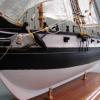
This is how the traveler ring looks after rigging it. The jibsail and foresail rigging is now completed. All that remains to rig are the two yards....once I make them. That will complete the rigging and then its the final stretch with a few additional details....anchors....flag....boarding ropes......and she is officially done.
-
Chuck reacted to PeteB in HM Cutter Cheerful 1806 by Chuck - FINISHED - 1:48 scale - kit prototype
Hi Guys
Stunning Work Chuck Ive loved following the build - as a newbie here I feel like I'm walking where angels fear to tread suggesting this but thought I might share something which is sort of between both your and druxey preferences just a simple way to hold lines till you want to permanently fix them without using glue or marking them.
When I started rigging I found I needed at least three hands until I came across some various sized electrical heat shrink tubing. I used it for taking the strain during shroud seizing and just adjusting and holding any lines fixed or running in position till you were ready to finally tie them off.
Just cut two or three pieces of tube - thread the line or rope thru then around the block or deadeye then back up thru the tube. Move them to a position above or below where you want to place the final seizing. Hit them with a hair-dryer to whatever tension you want - easy or tight slip or no slip and when you've finished the final seizing take a no 11 blade to the rubber and it falls off with no marks or need for clean up.
.
Apologies for the Photo its from my Billings candidate for a Viking burial. Cheers Pete
-
 Chuck got a reaction from PeteB in HM Cutter Cheerful 1806 by Chuck - FINISHED - 1:48 scale - kit prototype
I am about to make the two yards for Cheerful and the center of each is eight sided. So I am going to start with a square stick and then turn it into an Octagon. I will round off the ends and taper them afterwards. I am using the 7/10/7 template to mark the stick so I can create the eight sided shape.
When I was preparing my square stock I thought that everyone would probably benefit from the template I am using and created. It will save you time so you dont have to make one. Attached is a PDF template that is prepared with the correct ratios. I have been using it all along to make the masts and other spars. Its a very handy template to have.
seventenseven.pdf
Chuck