-
Posts
5,200 -
Joined
-
Last visited
-
 michael mott reacted to a post in a topic:
Sail feedback request, Mondfeld method
-
 WalrusGuy reacted to a post in a topic:
Bristol Pilot Cutter by michael mott - 1/8 scale - POF
-
 WalrusGuy reacted to a post in a topic:
Bristol Pilot Cutter by michael mott - 1/8 scale - POF
-
 KeithAug reacted to a post in a topic:
Cangarda 1901 by KeithAug - Scale 1:24 - Steam Yacht
-
 Baker reacted to a post in a topic:
Bristol Pilot Cutter by michael mott - 1/8 scale - POF
-
 michael mott reacted to a post in a topic:
Billy 1938 by Keith Black - FINISHED - 1:120 Scale - Homemade Sternwheeler
-
 michael mott reacted to a post in a topic:
HMCSS Victoria 1855 by BANYAN - 1:72
-
 Keith Black reacted to a post in a topic:
HMCSS Victoria 1855 by BANYAN - 1:72
-

HMCSS Victoria 1855 by BANYAN - 1:72
michael mott replied to BANYAN's topic in - Build logs for subjects built 1851 - 1900
Glad to hear that after a health scare and getting fixed up you are climbing back in the saddle.... er bosun chair. Merry Christmas from snowy Canada! 15 c Luxury we ar, lucky to get to 0c tis - 21c as I fumble with cold digits. Michael- 1,021 replies
-
- gun dispatch vessel
- victoria
-
(and 2 more)
Tagged with:
-
 michael mott reacted to a post in a topic:
HMCSS Victoria 1855 by BANYAN - 1:72
-
 Keith Black reacted to a post in a topic:
Cangarda 1901 by KeithAug - Scale 1:24 - Steam Yacht
-
Congratulations on your 50th anniversary Keith, more superb details, I too like the grills. Even when we know that certain details cannot be seen by us mortals once things get closed up or around corners, there is a deep satisfaction in knowing that the detail is there, plus of course the challenge of making them. Which is much of the fun in this wonderful hobby. Ialways think about all the intricate joints in the assembly of the framing on the ships of the line that then get covered by planking. Merry Christmas to you, Ann and family. Michael
-
 michael mott reacted to a post in a topic:
Cangarda 1901 by KeithAug - Scale 1:24 - Steam Yacht
-
 Mark P reacted to a post in a topic:
HMS ANSON 1781 by albert - 1/48 - 64 guns
-
 Kenneth Powell reacted to a post in a topic:
Bristol Pilot Cutter by michael mott - 1/8 scale - POF
-
Good morning everyone, well it is morning here, thanks for all the kind welcomes. Eyes are settling down, it is strange now having to get used to becoming farsighted after being nearsighted all mi life. my temporary reading glasses from the pharmacy are definitely a help but have to take the off when I look up as things go blurry. only a few more days before I can start working in the workshop . Michael
- 2,215 replies
-
Hello everyone, Wow Hard to believe it has been so long since my last post here. Had to go to the pharmacy yesterday to get some interim reading glasses after the second cataract surgery in the last three weeks, I was trying to see the screen and trying to type with one finger while creating a pinhole with my left hand to bring the letters into focus. Then i had the brilliant Idea to make my pree cataract surgery glasses into pinhole ones!.... well you can all guess how well that worked out. Hence to trip to purchase some reading glasses after trying to type with the Visor magnifying set I use when doing fiddly work, I had to keep lifting the visor to find where the mouse had gone, It seem comical writing about it now but yesterday it was very frustrating. All that said I'm still very busy now with having taken on 3 different secretary/treasurer roles in my masonic groups, still painting and Keep thinking about what to get back at on this cutter. having just finished looking through Keith superb work on the interior of his latest masterpiece, I am inspired to get back on a few bits, I will see how i get on with these reading glasses in a week can't go into any dusty places for a week according to the Ophthalmologist. But I can catch up on some of the great work being done here in Modelshipword. Merry Christmas and happy new year to one and and all. Michael
- 2,215 replies
-
 michael mott reacted to a post in a topic:
1876 Parcel van by michael mott
-
 michael mott reacted to a post in a topic:
HMS Bellona 1760 by SJSoane - Scale 1:64 - English 74-gun - as designed
-
AJohnson started following michael mott
-
 michael mott reacted to a post in a topic:
Cast Metal and Brass
-
 michael mott reacted to a post in a topic:
Atlas craftsman lathe
-
 michael mott reacted to a post in a topic:
Atlas craftsman lathe
-
Mark having just spent the better part of the morning catching up with your work on this amazing model, I fell like going and sitting in the corner and rethinking my approach to all things model related. Your tenacity to solve the methods of construction and details are enviable, I wish I had the patience. Have you found a bit of proper English boxwood yet? if not send me a pm as I have a reasonable amount still and depending on the size of what you need I could send you some. I have really enjoyed catching up on your build, love all the ways you use your tools and organize them as well. Michael
-

1876 Parcel van by michael mott
michael mott replied to michael mott's topic in Non-ship/categorised builds
Tom I spent a lot of time contemplating the purchase of the hex plate, it certainly was not cheap but has 20 different hex sizes and for me it has enable me to create both nuts and bolts of many scale sizes out of a few diameters of rod. The scale threads are a hole different matter and are a limiting issue. Michael -

1876 Parcel van by michael mott
michael mott replied to michael mott's topic in Non-ship/categorised builds
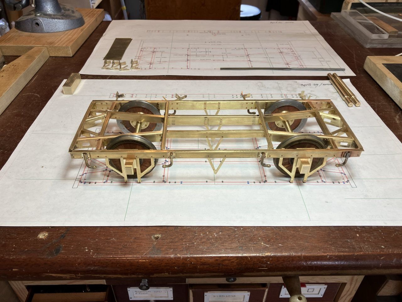
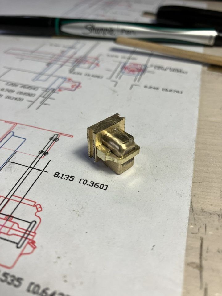
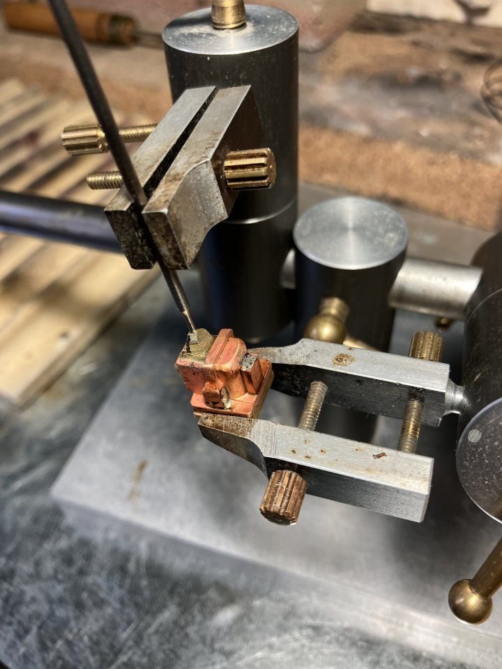
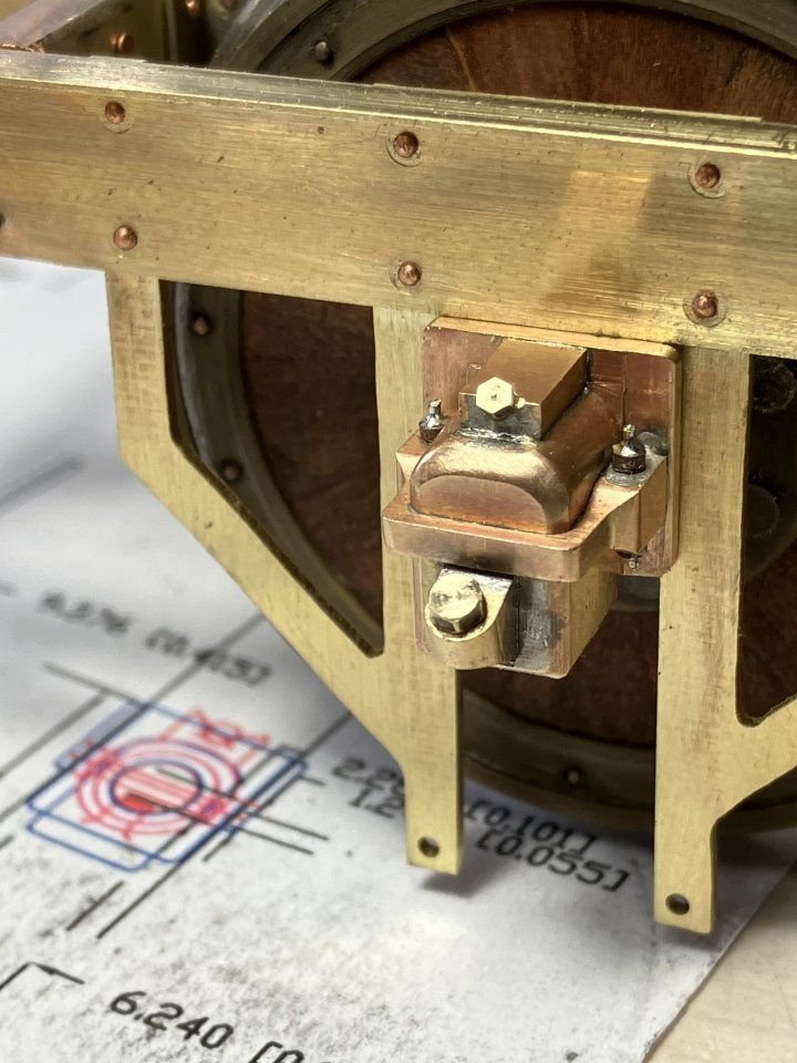
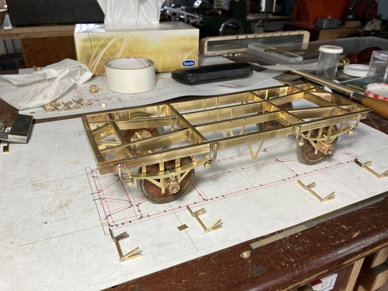
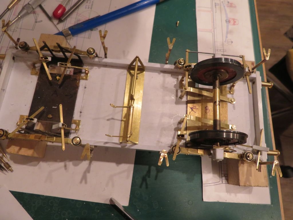
Not a lot more progress to report on this project which has been challenging I feel that it will not be worked on much over the next few months as a couple of commitments that need to be completed by the new year take precedence. A few more pictures of the work done over the last year. After the springs were completed the next work involved preparing the wheel bearings These are basically a solid block of brass with some additions added to dress it up. the first picture shows the basic block with the initial shaping and fitting to ensure a good slide fit into the "W" irons. The prototype is manufactured out of two castings bolted together and to replicate this I slotted a piece of brass into the block with the thicker area that would hold the bolts. The insert and a top block were soldered together using some high temperature soft solder, my third hand has been very handy during this entire project so far. Once the soldering was done and cleaned up holes were drilled for the various bolts and oil caps, these were formed from a few different diameters of brass rod annealed and pulled through my Hex draw plate. the bolts are glued in place with AC glue. Now with the springs and bearings the under-frame is beginning to look like the contemporary frames of the period. The frame has a decent amount of springiness. to be continued Michael -

1876 Parcel van by michael mott
michael mott replied to michael mott's topic in Non-ship/categorised builds
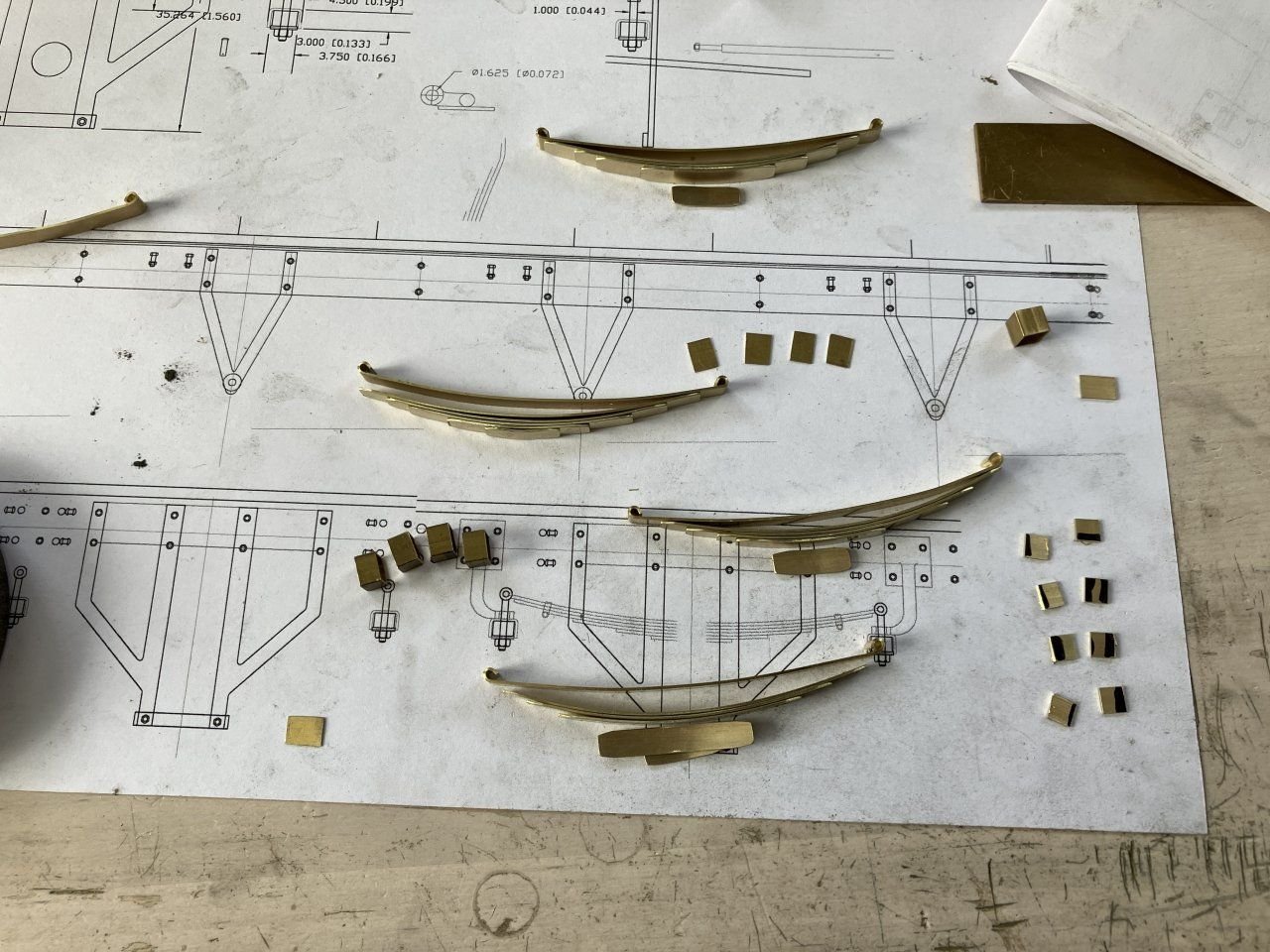
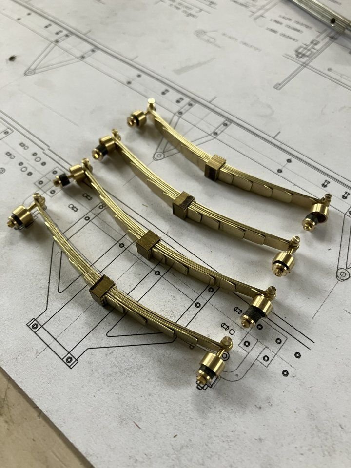
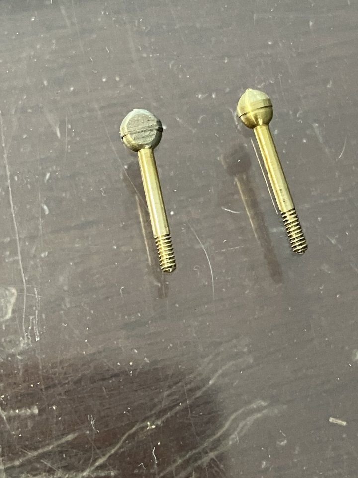
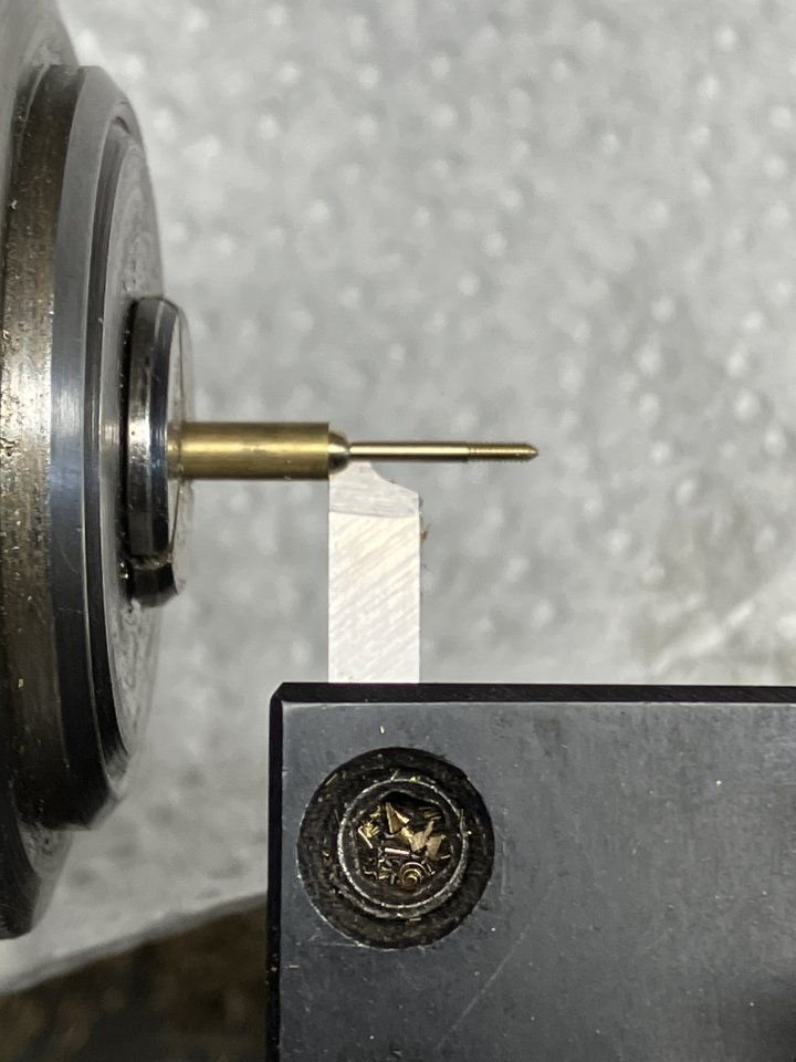
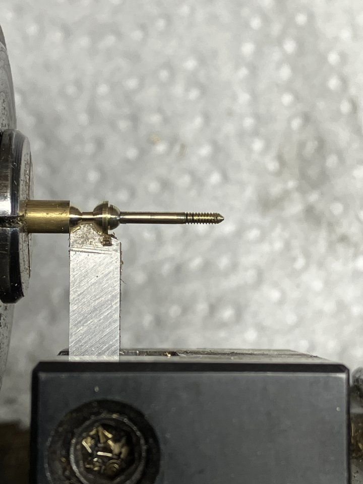
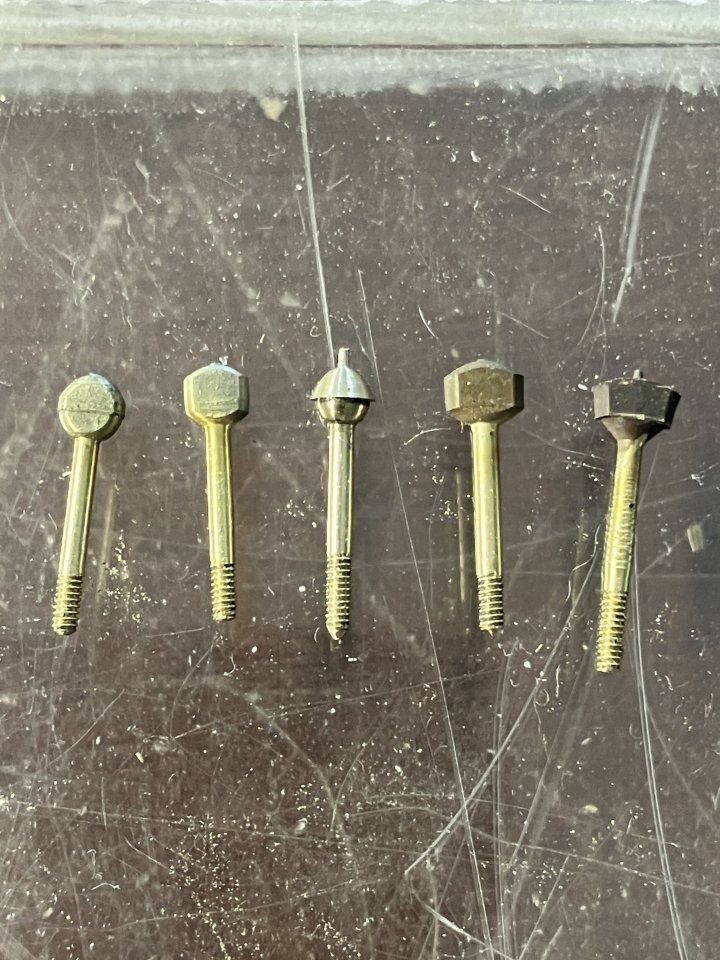
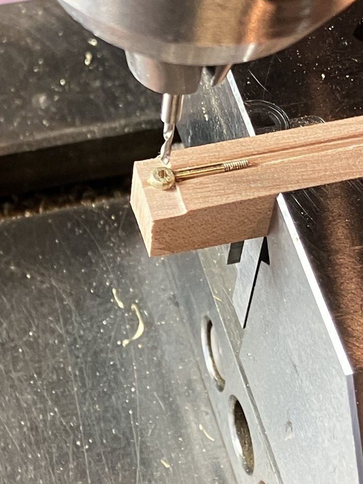
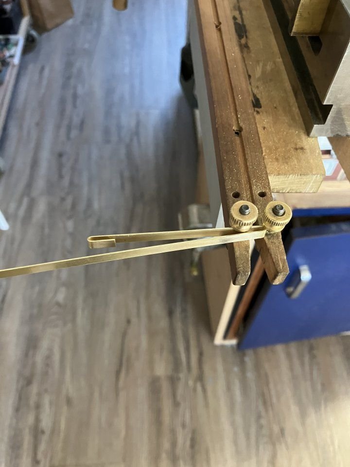
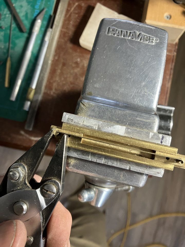
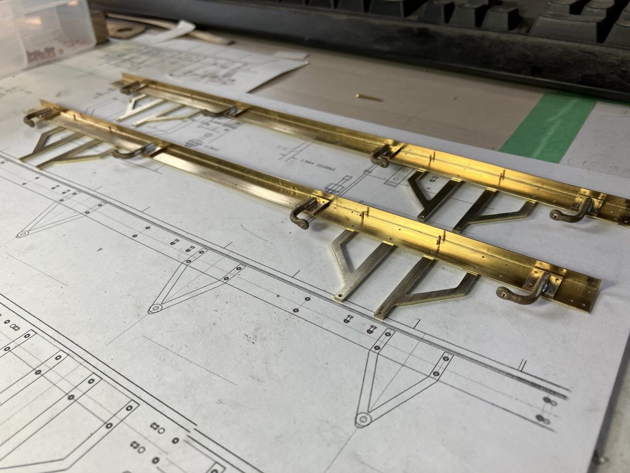
A few more pictures of the progress of the van. The next area to tackle was the springs, I thought about this for a while, and decided that because this van would not get a lot of use in a real sense that I prefer building to running the models, that Hard brass sheet would be sufficient for the springs. The top leaf is the most complicate I had to make a small jig to ensure that the loops at the ends were consistent, but rather that a fixed jig I opted for an adjustable one. first yo bend the strip to length and then using the jewelers saw to cut the excess off then to close the loops with some parallel jaw pliers The rest of the leafs were straight forward , to get the correct curve was a trial and error wood jig reducing the diameter of the curve until the correct bend was achieved then it was just a matter of cutting to length and drilling the hole in the centre after bending. The reason for bending the curveafter was to avoid the kink in the middle that was caused by there being less material and so it bend more easily at that point. Next were the spring hanger bolts, I used the similar method to the one I used to make the shackles for the Cutter only I also needed a thread and only one forged end. Beginning with 1/8th hard brass rod I used a single form tool in one pass to reduce the diameter and form one end of the bulb that would get flattened, and in order to thread the end 00x90. Then after indexing the tool forward ised it to form the other end and part off in one motion, a little crude but it worked. A picture showing the evolution of the method arrived at above. a simple wooden holder to drill the holes before they were added to the top leaf. The rest of the hanger bolts was a simple inverted cup to hold the 3/16 section of "O" ring with an .047 inch hole drilled through it to represent the rubber dampening part a flat washer and nut completed the assembly. a bit of square tube was used to form the central keeper and a pin through to keep it all aligned. to be continued Michael -

1876 Parcel van by michael mott
michael mott replied to michael mott's topic in Non-ship/categorised builds
I am still working out how to obtain miniature creosote barrels in order to treat them😉 Druxey I am honored to be thought of in the same vein as Gerald Wingrove , I have been an avid admirer of his incredible work for over 50 years, thank you. Michael -

1876 Parcel van by michael mott
michael mott replied to michael mott's topic in Non-ship/categorised builds
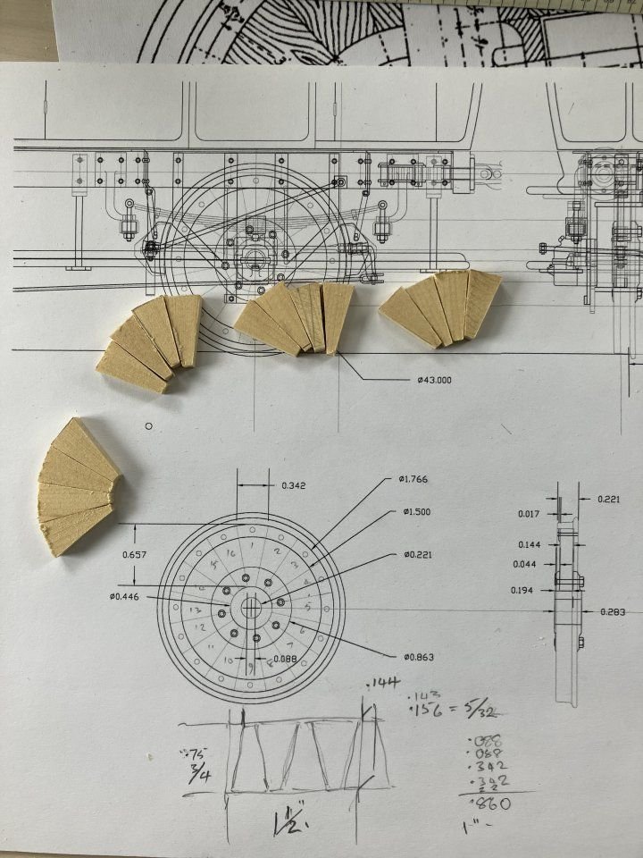
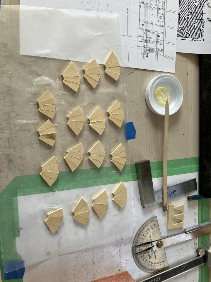
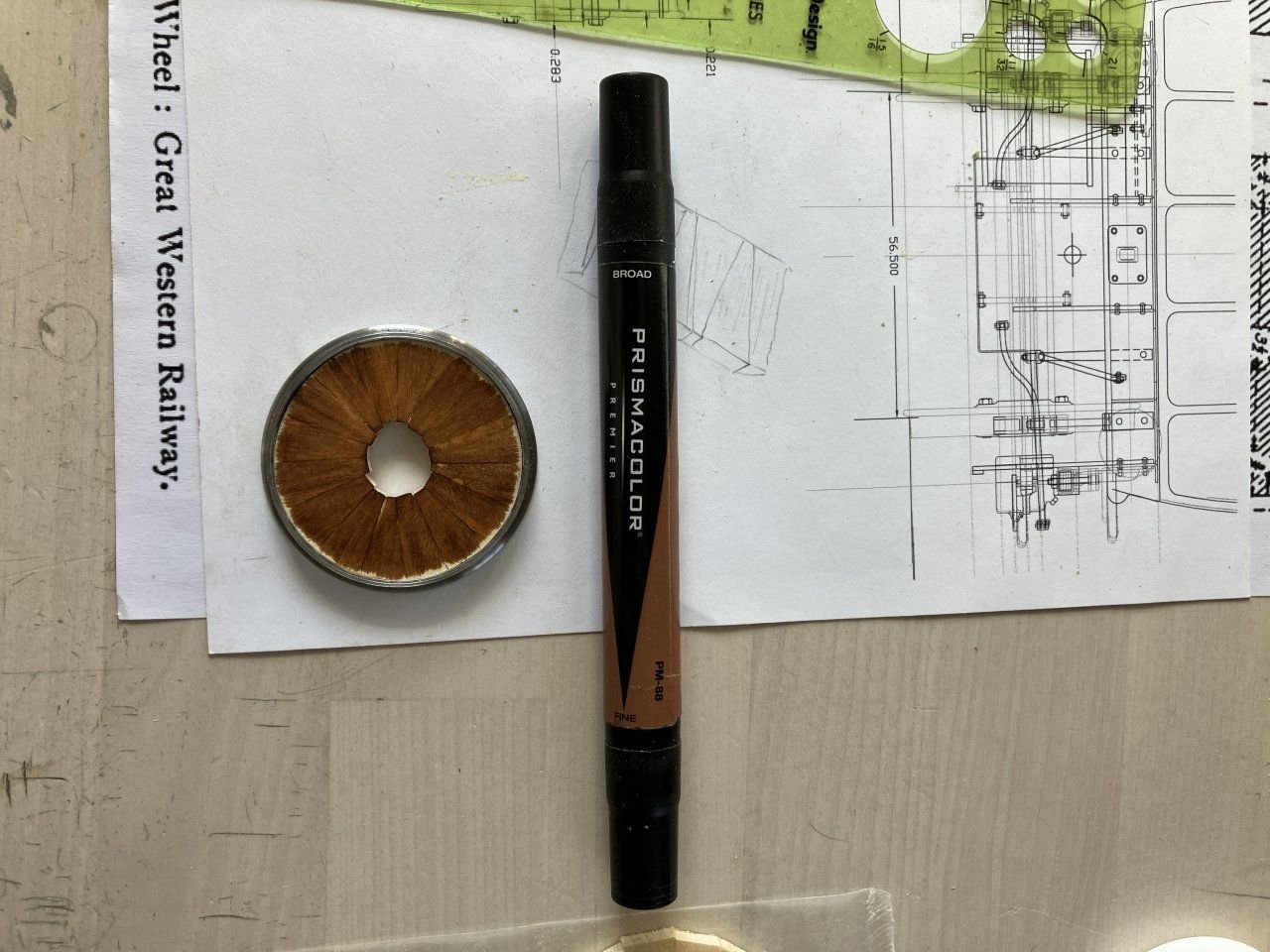
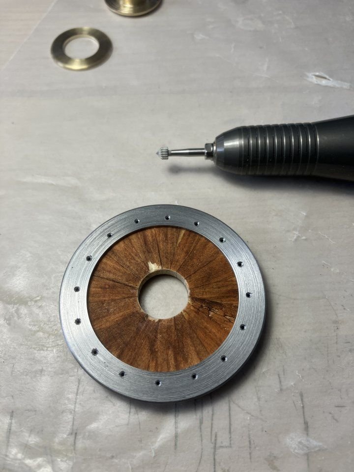
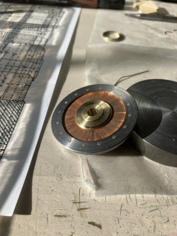
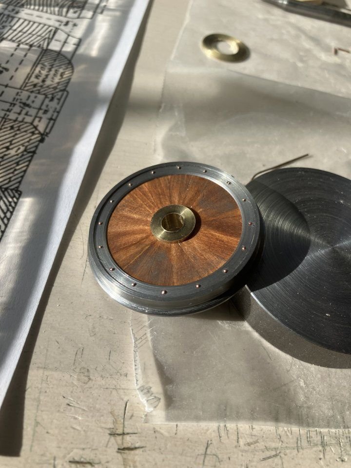
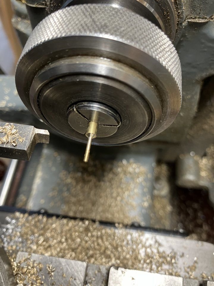
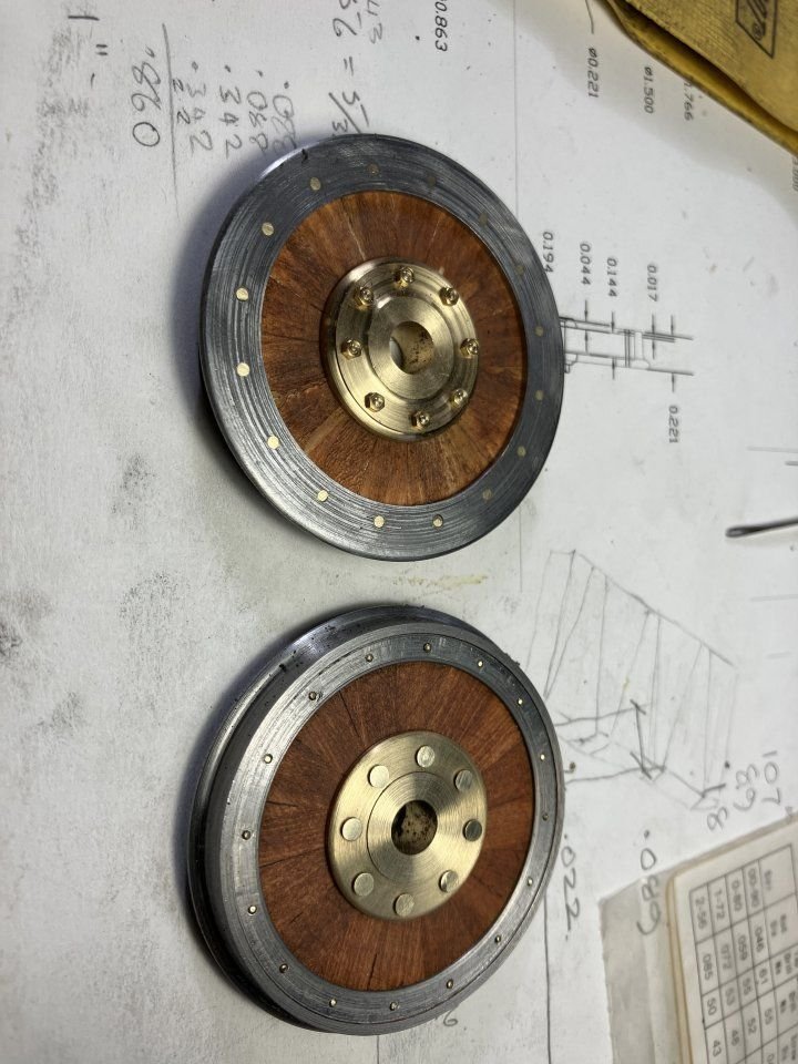
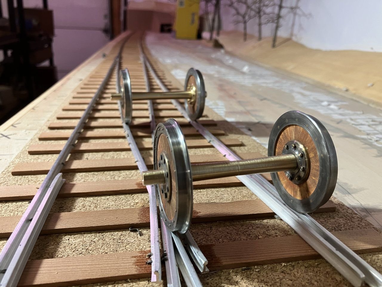
Continuing on then here is a bit more of the progress much of this work has been done over the last year. The wheels are a combination of wood and steel the wheels used on passenger vans etc were Maunsell wheels the idea that by insulating the steel tyres from the hubs with hardwood would eliminate the noise generated by steel on steel over the joints etc. after choosing some yellow ceder for texture and ease of working I cut four sets of 16 oversize in length wedges and began gluing them together in pairs. after a while the set of pairs became sets of four, and so on until I had two halves that were easy to get flat to match and then glued those together, these were then trimmed on the outsdide diameted with a jewelers saw and slowly sanded with sanding sticks until they slipped snugly into the tyres, then colored with the pentel pen. After the wood had been glued to the tyre I was able to bore the centre hole for the hubs, the wheel was then set up on the rotary table to bore the holes through the steel ring on the front face through the wood and the tyre for the 1/32 copper rivets. ( eventually had to make them from brass because I did not have enough of the right length so they were turned and annealed ) the backside was countersunk with the small hand held tool. the first wheel with some copper rivets from the back and then flipped over to show the front side with the retaining ring Using the same method a the sets of turned brass rivets I machined up some flat-head brass 00x90 bolts to assemble the hubs. then bolted them together. and finally set loosely on the axles. to be continued. Michael I chose brass because I had the right diameter to do the work. -

1876 Parcel van by michael mott
michael mott replied to michael mott's topic in Non-ship/categorised builds
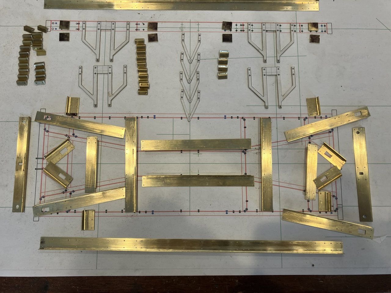
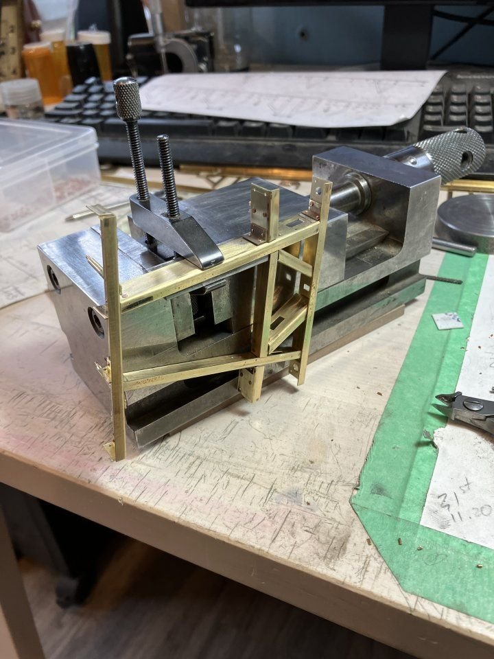
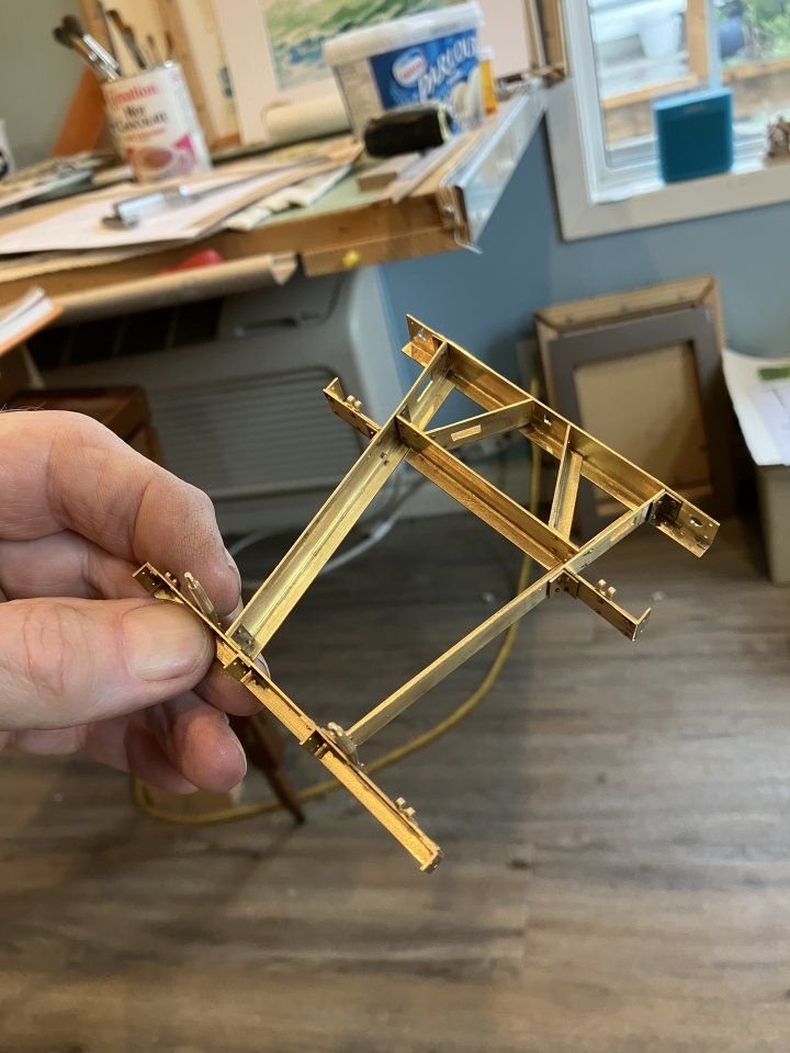
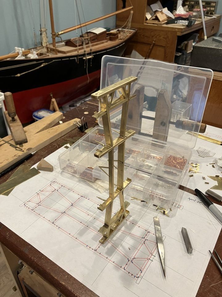
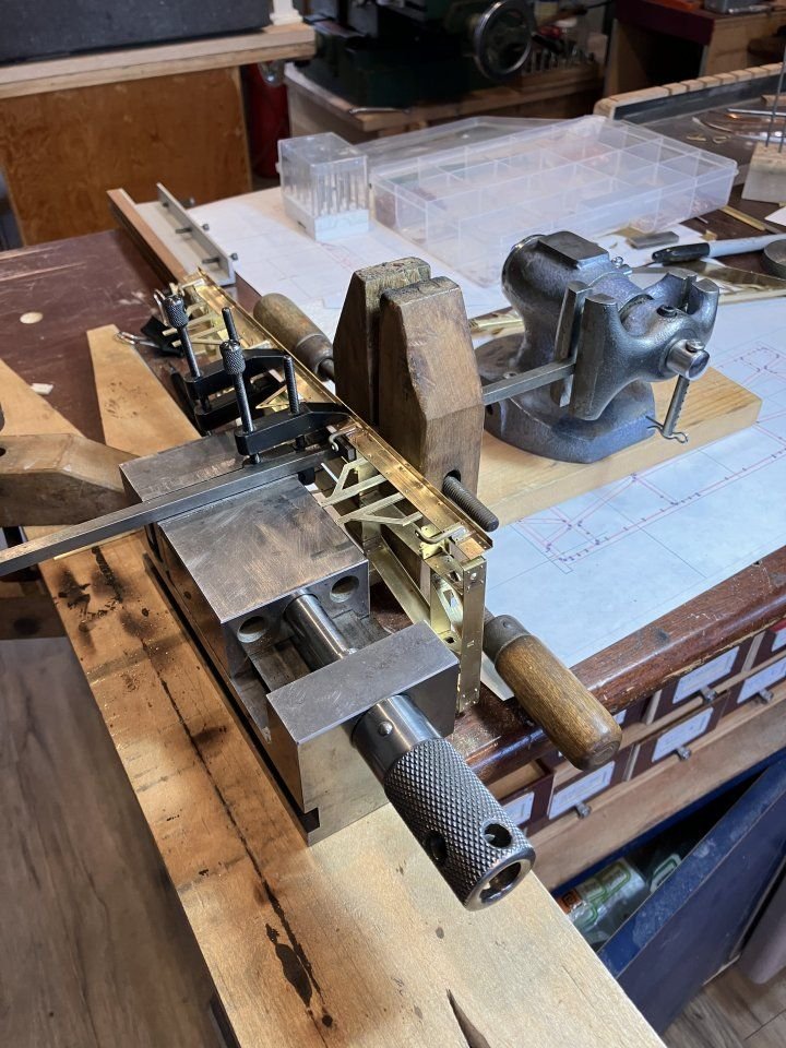
Thank you all for your kindness and welcomes. Here are a few more pictures of the restart as Druxey so aptly called it. After bending up the angles I then used a vice and a little work with a chunk of mild steel flat bar and suitable hammer to tighten up the corner. Next a set up on the mill to cut each leg of the Angle to the scale 3 inch x 9 inch accurately this was a slow process and a couple of hiccups before all the needed section was produced. The individual parts were marked out and cut to length with the inevitable mistakes because of the right and left handing of angles and holes. I now have a number of extra parts for some other purpose down the road so to speak. A few test samples were made of the riveting of corners a couple of which were very challenging but I wasn't giving up. ( More trinkets in the spares bin.) One of the reasons for some of the changes was my changing the layout of the frame as there is no extant drawing of this particular under-fame and during the late 1800's the Great Western Railway was undergoing all sorts of developments with the design of their rolling stock and Locomotives, as were all the other companies. Once I was happy with my conjectural configuration based on the best practices and closest other frames of the same era I began riveting the frame together with 1/32 copper rivets.(very challenging indeed) I ended up with all sorts of oddball configurations of vices clamps and bars in order to sequentially put it all together in all it took a few weeks and even then a couple of time I had to chisel off a connection because I had boxed myself in or the holes did not quite line up. The sole bars were the last parts to add to complete the main structure and again I ended up taking a long time thinking about how to get these parts together. Another oddball combination of vices and clamps allowed me to get the job done. (where are those nano robots when you need them?) we are getting there...... to be continued Michael -
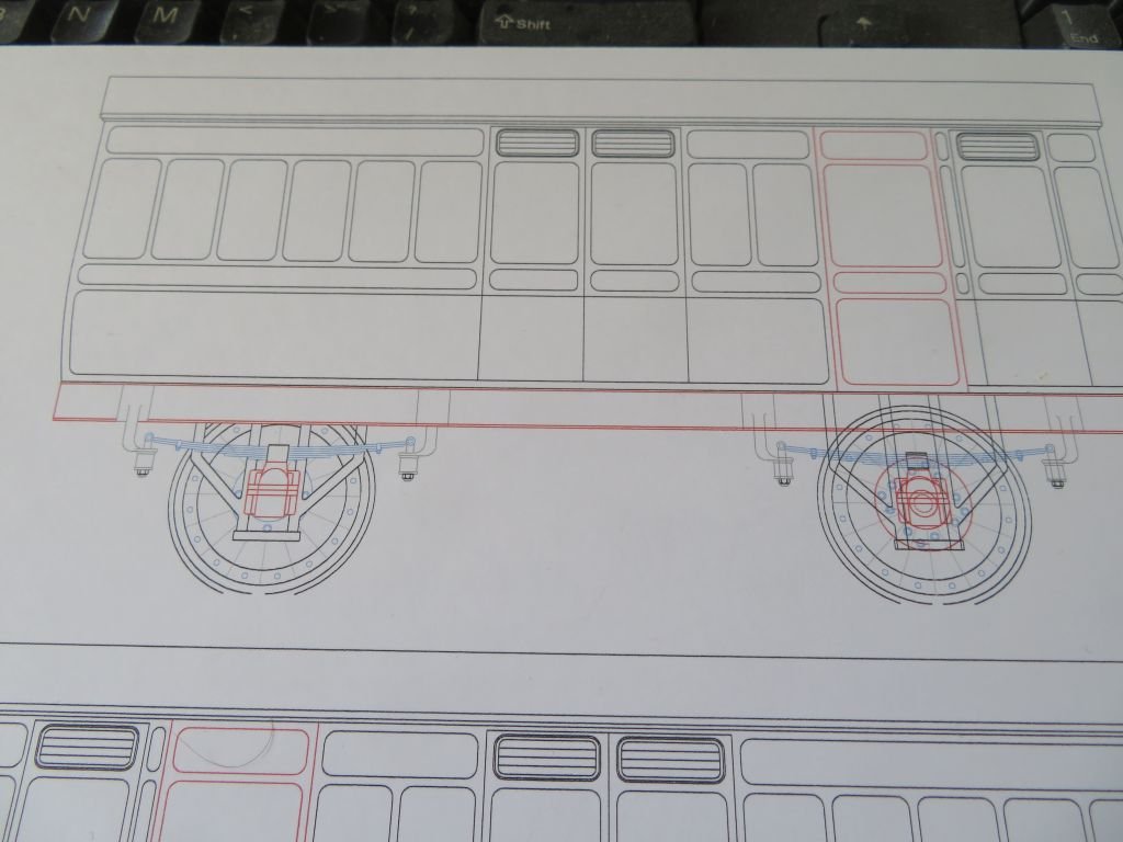
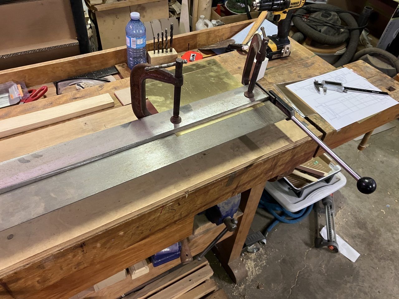
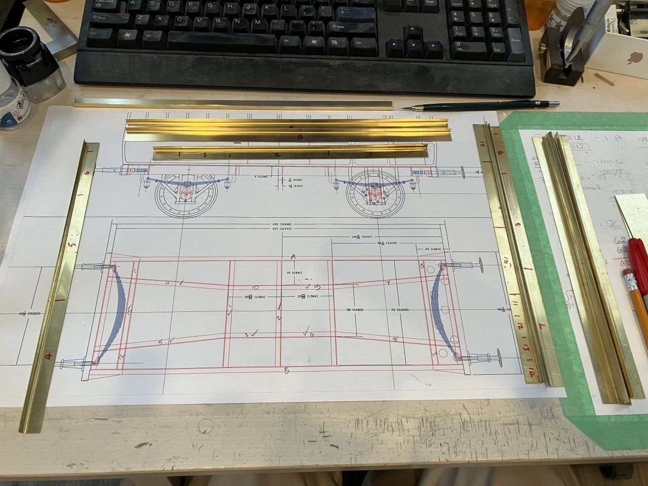
OK, here is what has been occupying my muse recently. It is a parcel van that is for Gauge 3 (63mm or 2.5 inch between rails) I challenged myself to attempt to build it using the same processes as the original with obvious substitutions regarding some of the materials for ease of building in some areas and for economical reasons, using what I had on hand rather than purchasing more materials. I did start building this model at the Gauge 1 scale (45mm or 1.75inch between rails) but changed after getting bogged down with wanting to make the undercarriage fully working including brakes. This is as far as the first model went, as many will already know I have no problem starting things over or changing up elements. Next was to make the metal structural parts for the frame this meant making a bunch of scale 3 inch by 9 inch angle, I cut strips of .020" brass and folded them on the brake. The angle needed more work to get it a bit more sharp in the corner. to be continued. Michael
-
Good morning everyone, I have not stopped building models just have been busy with my masonic duties I am again the Master of my lodgeand have other duties in some concordant bodies. What little time I spend in the workshop these days requires walking past the cutter which sits waiting patiently for my energy to return to it. I have been doing little work on my model railway endeavors particularly an 1876 great western parcel van which has been particularly challenging. I could post a picture or two if anyone is interested. Michael
- 2,215 replies
About us
Modelshipworld - Advancing Ship Modeling through Research
SSL Secured
Your security is important for us so this Website is SSL-Secured
NRG Mailing Address
Nautical Research Guild
237 South Lincoln Street
Westmont IL, 60559-1917
Model Ship World ® and the MSW logo are Registered Trademarks, and belong to the Nautical Research Guild (United States Patent and Trademark Office: No. 6,929,264 & No. 6,929,274, registered Dec. 20, 2022)
Helpful Links
About the NRG
If you enjoy building ship models that are historically accurate as well as beautiful, then The Nautical Research Guild (NRG) is just right for you.
The Guild is a non-profit educational organization whose mission is to “Advance Ship Modeling Through Research”. We provide support to our members in their efforts to raise the quality of their model ships.
The Nautical Research Guild has published our world-renowned quarterly magazine, The Nautical Research Journal, since 1955. The pages of the Journal are full of articles by accomplished ship modelers who show you how they create those exquisite details on their models, and by maritime historians who show you the correct details to build. The Journal is available in both print and digital editions. Go to the NRG web site (www.thenrg.org) to download a complimentary digital copy of the Journal. The NRG also publishes plan sets, books and compilations of back issues of the Journal and the former Ships in Scale and Model Ship Builder magazines.




.thumb.jpeg.fc5d633a7b34428fcf19419a73d56d55.jpeg)


.thumb.jpg.62d1d69fed1f32364417cb1f9cdeb009.jpg)


