michael mott
-
Posts
5,200 -
Joined
-
Last visited
Content Type
Profiles
Forums
Gallery
Events
Everything posted by michael mott
-
 This is my hope. I have learned so much from all of the work that has been posted here by others. This site is more than a gold mine in my view. Carl I think that this will meet with your approval, thanks for the thought. I picked up my brass wire today and am doing some tests with it. Michael
- 749 replies
-
- 13
-

-
- albertic
- ocean liner
- (and 2 more)
-
Mike one of the things that I liked about watching the video of the operation of the tool was the fine control that comes with the ease with which the carriage moved and the simplicity of gripping the part being cut. What is the finest blades that work well with this tool relative to the fine jeweler's saw blades? I like to use a # 3/0 for thin wood and # 7/0 for thin brass. Michael
-
Thanks Joe, sometimes I wonder if I am being a little too detailed. My hope is that there are nuggets of info that will be useful. Michael
- 749 replies
-
- 5
-
-
- albertic
- ocean liner
- (and 2 more)
-
Hi Nils, they are made of brass, I cannot see yet if they are lost wax (which I doubt) or are a composite of rods tubes and forged elements the tall open type are a combination of tube and turned parts. The shorter large scoop type appear to be assembled as well. All of the chipped paint on them have exposed a brass color. Michael
- 749 replies
-
- 4
-
-
- albertic
- ocean liner
- (and 2 more)
-
Jan, me too, and I have to deal with them. The fall would have been a smooth arc it was the chair in the way and the glass case being shattered then the sudden stop at the end that did all the damage. Good point Carl. I shall rework it. Michael
- 749 replies
-
- 3
-
-
- albertic
- ocean liner
- (and 2 more)
-
Mike I had to follow up on your 'Chevalet de Marquetry' What a neat tool it could also be used for frames. your shop looks great. Michael
-
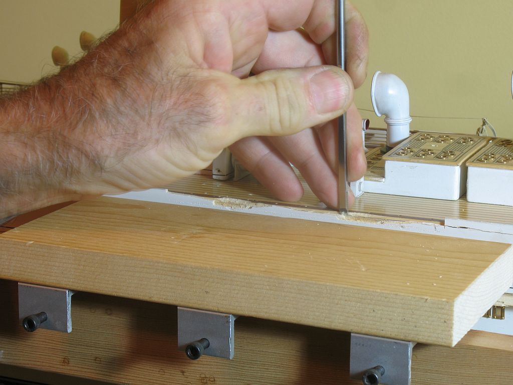
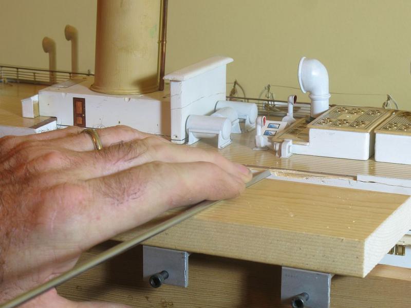
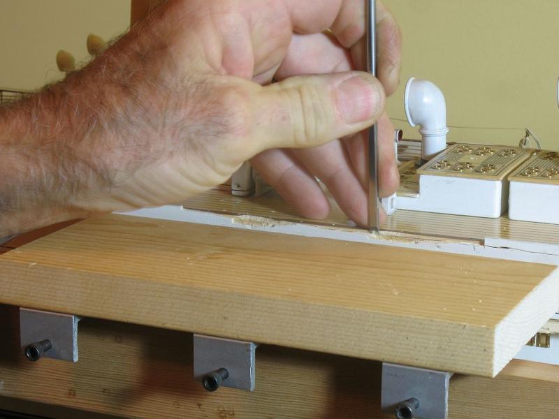
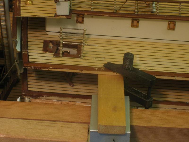
Thanks for your thoughts on this area Druxey and Carl. Before I glue on the lifeboat deck I still needed to fix the top part of the lifeboat deck structure. I set up a flat plate that I could use as a guide for the pairing chisel. Once the damaged area was removed I fitted a new piece of maple this will get painted on the top inside edge before it gets glued in place. A lot of little steps it seems. Michael

- 749 replies
-
- 19
-
-
- albertic
- ocean liner
- (and 2 more)
-
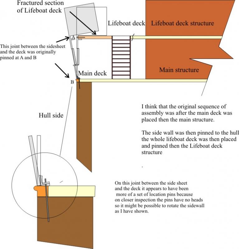
No scrap that Idea, that they were locators only. The headless pins are for the lifeboats. The side sheet ones are small headed pins, it will still work though, I pushed a couple of pins in partially and the side wall will lean out. So the deck will be glued first. Michael
- 749 replies
-
- 6
-
-
- albertic
- ocean liner
- (and 2 more)
-
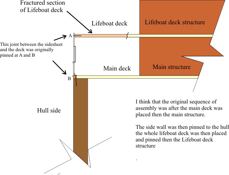
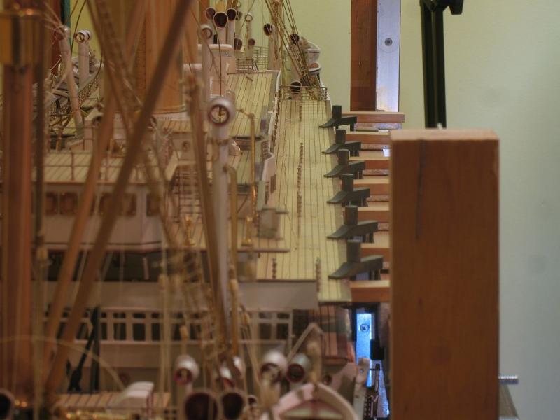
Druxey and Carl thinking more about this after your comments and having a closer look at the pins I think that it will be possible do something very similar the difficulty is mostly at the bow end as the next illustration shows. This come closer to what you have suggested Carl Michael
- 749 replies
-
- 6
-
-
- albertic
- ocean liner
- (and 2 more)
-
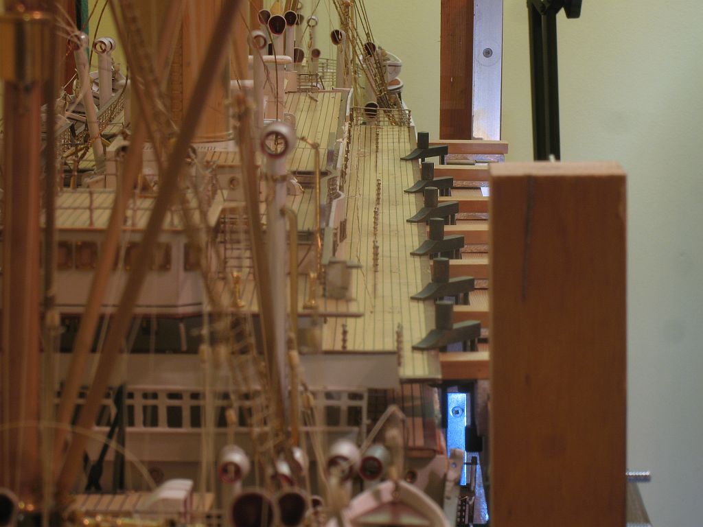
John thanks for the compliment. I am wondering what the members think of my next issue. the following picture shows a partial cross section of the hull and side wall. What I am concerned about is the sequence of gluing the fractured part of the deck back on before I put the side on. If I do that it will be difficult to put the pins in at B the pins at at A are not a problem If I put the side back on first it become quite difficult to slip the lifeboat deck part back into place especially at the bow end. I am thinking that Possibly I could use a clear silicone glue at the base of the side wall and slide it in after the lifeboat deck is glued and set. Thoughts? Michael
- 749 replies
-
- 5
-
-
- albertic
- ocean liner
- (and 2 more)
-
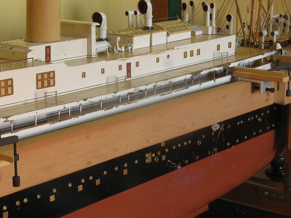
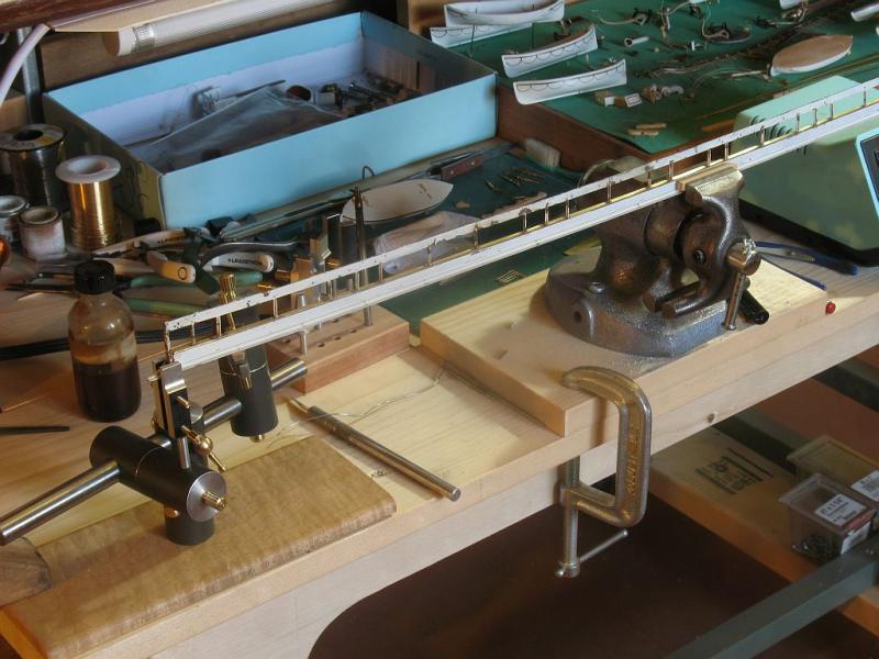
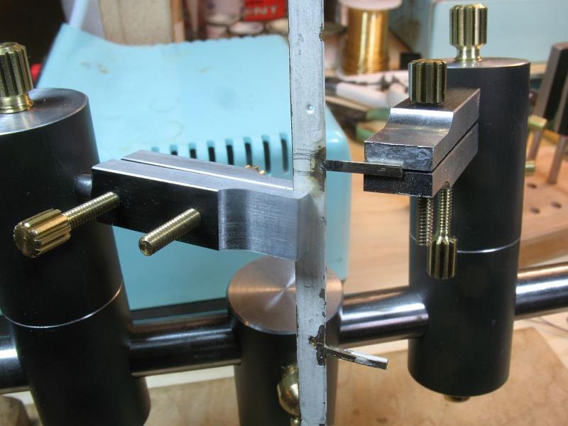
Thanks for the supportive comments. Druxey.... yes its probably going to work out to 5c per hour. But I'm not really counting. Bob they appear to be a white plastic almost bone-like in color. Today I soldered the side back together. This picture shows it just resting in place, I am pleased with the fit. My third hand became a fourth this morning. I am really happy I took the time to make this tool, the control is beyond what I expected. Now for the clean up and sorting out how to reassemble back onto the deck, it was originally fitted with small pins, likely pushed in with some sort of miniature pin pusher....... why do I sense another tool needing to be made? Michael
- 749 replies
-
- 14
-
-
- albertic
- ocean liner
- (and 2 more)
-
Hi Keith yes I am using soft solder, it is what Bassett Lowke used. I get the stitches out on Thursday. Michael
- 749 replies
-
- 8
-
-
- albertic
- ocean liner
- (and 2 more)
-
Now that is a great attention to detail! some of us might have taken the easy route and built them at right angles to the slope. Michael
-
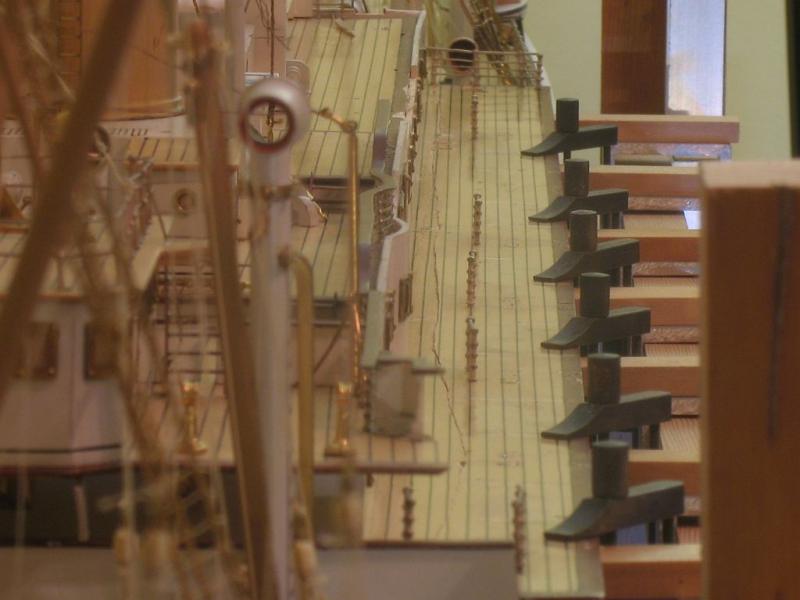
Bob the tool will serve a number of functions, I used it today to clamp on the strip of wood that is under the metal side piece first. There was a fair chunk gouged out of the piece so I spliced in a bit of wood first, and shaped it. The I spent at least an hour walking back and forth from the shop to the clean room getting the large section of the metal side back to conforming to the side sheer of the main deck. All the clamps are set as stops to position the side the important thing was to be able to place it and have it seat properly without any pressure. once the lower section was set then I used a card template to put the proper curve back into the upper piece using the same method that I used to get all the twists out of it in the first place. Next on the list was to replace the missing posts on the upper part. On close inspection the section that was used looked a lot like some very small nickle silver "N" gauge rail so I cut up some code 70 rail filed off the head of the rail which left a t section of nickle silver basically the same size as the original posts. I used the new clamp fixture to do the soldering. Michael


- 749 replies
-
- 21
-
-
- albertic
- ocean liner
- (and 2 more)
-
A Lorch Micro-Mill that never was ...
michael mott replied to wefalck's topic in Modeling tools and Workshop Equipment
Lovely work on the restoration Wefalck. Michael -
Jeff have you tried Jellutong? it carves like butter with no discernible grain. we used it a lot in England for patterns and architectural models. sands very well too. I can give you some next time I'm in Edmonton. Michael
-
Beautiful work on the mast Chuck, what paint are you using for the black? Michael
- 1,051 replies
-
- 3
-
-
- cheerful
- Syren Ship Model Company
- (and 1 more)
-
Looks great Dave. The small details just keep accumulating, bringing more and more depth to the overall look. Michael
- 962 replies
-
- 3
-
-
- sovereign of the seas
- ship of the line
- (and 1 more)
-
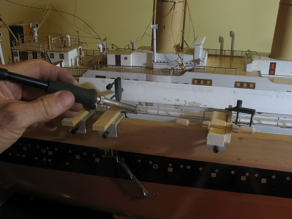
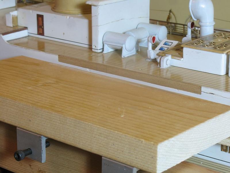
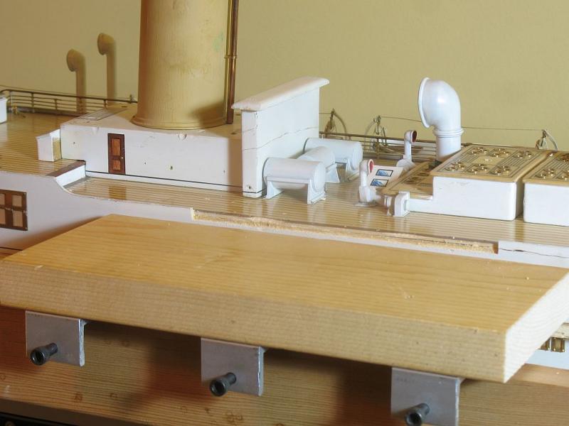
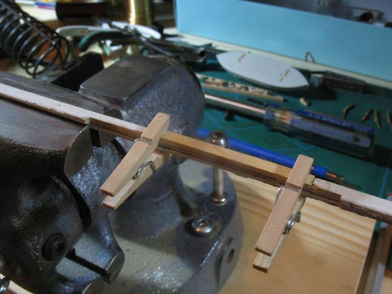
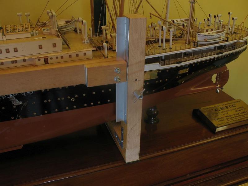
Thank you to all the visitors. I spent the rest of the afternoon making the top units, they were sliced off some 1 1/2 x 3/4x 1/8th thick scrap channel from the scrap box. The screws are 8x32 and the top wood is 1/4 x 1/2 x 3" Jellutong. The fracture line is visible at the moment on the dry run assembly, when it is finally tweaked ready for glue the line will hardly be visible. Have started to do some mix testing for the bottom paint color, it is also a simple way to fill the slight indents with paint Michael

- 749 replies
-
- 22
-
-
- albertic
- ocean liner
- (and 2 more)
-
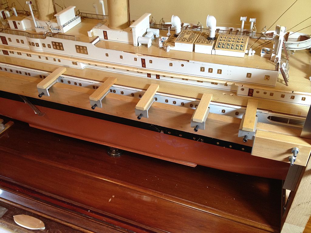
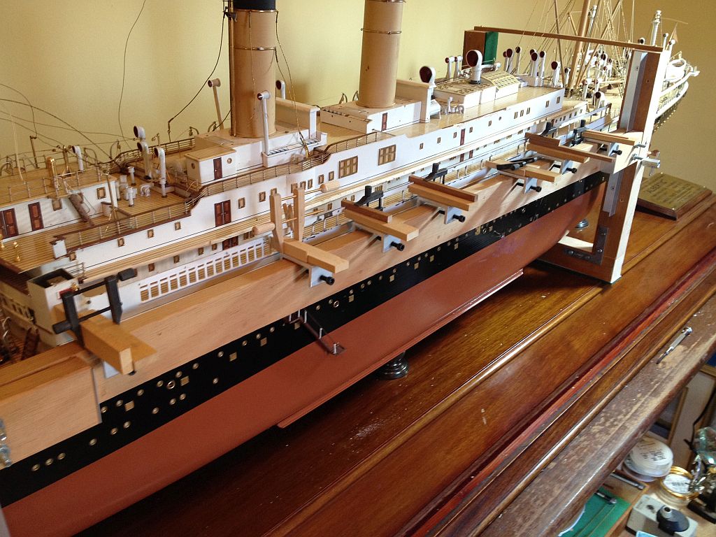
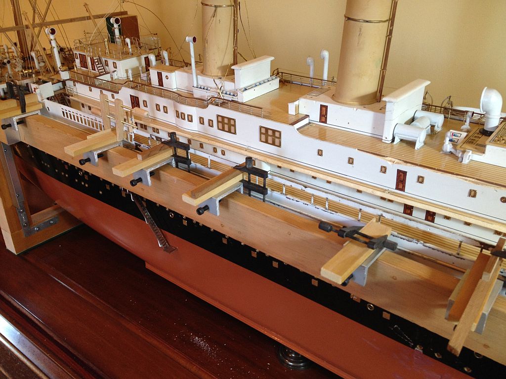
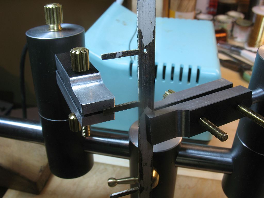
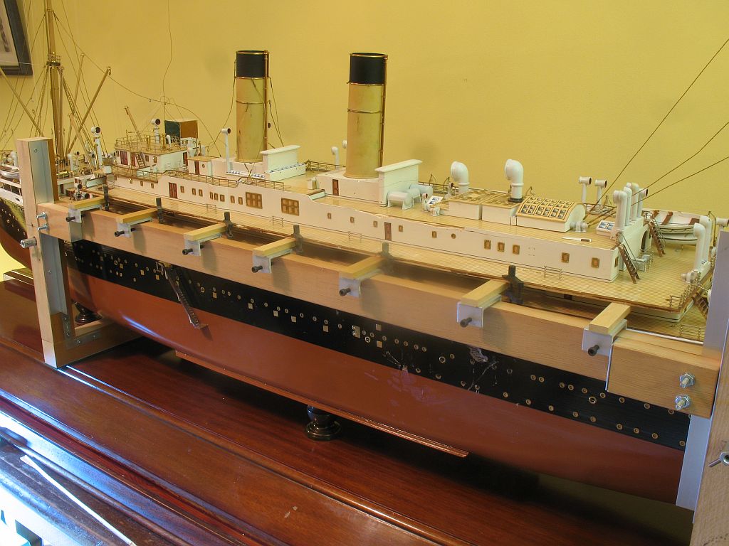
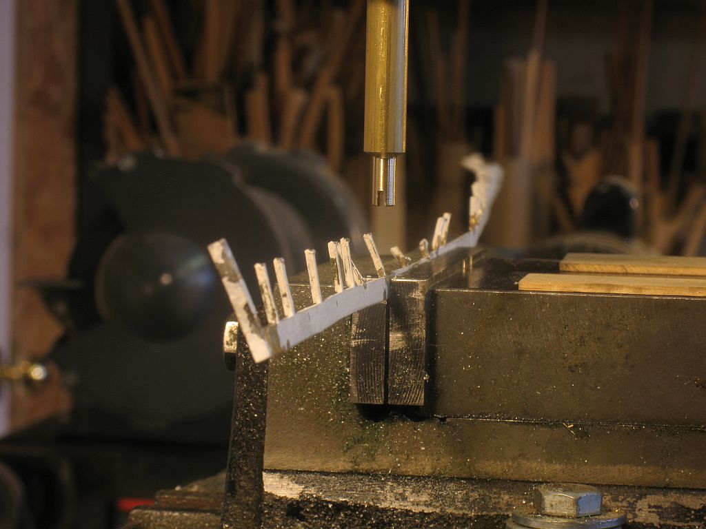
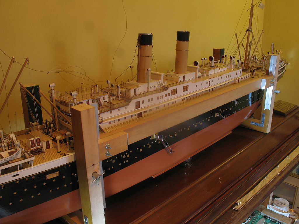
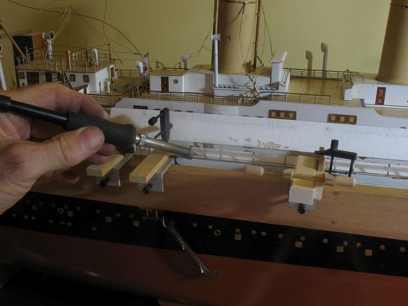
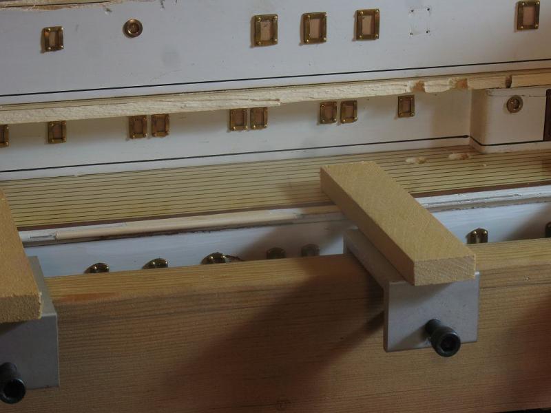
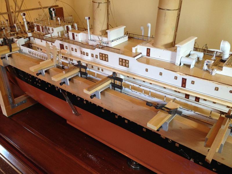
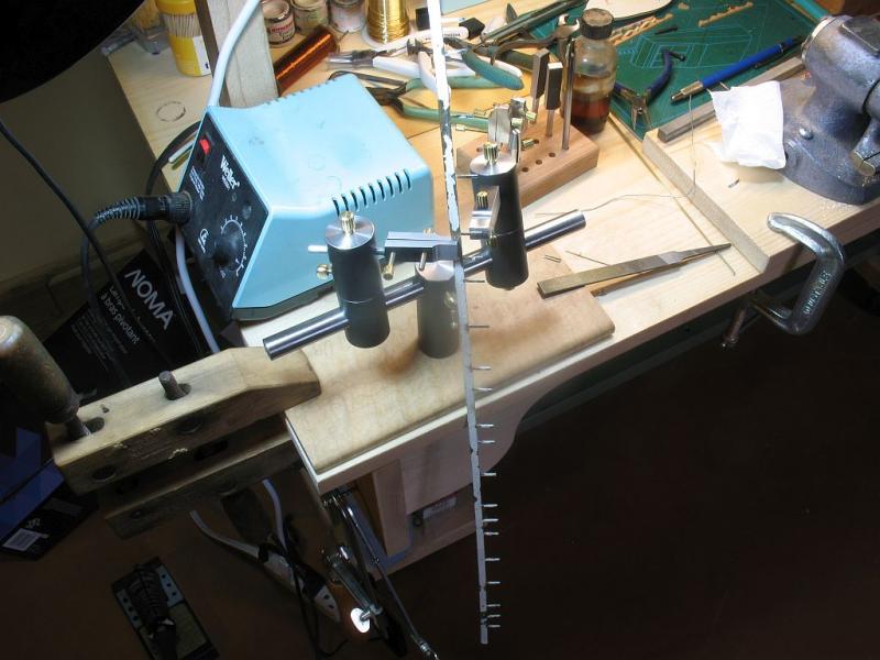
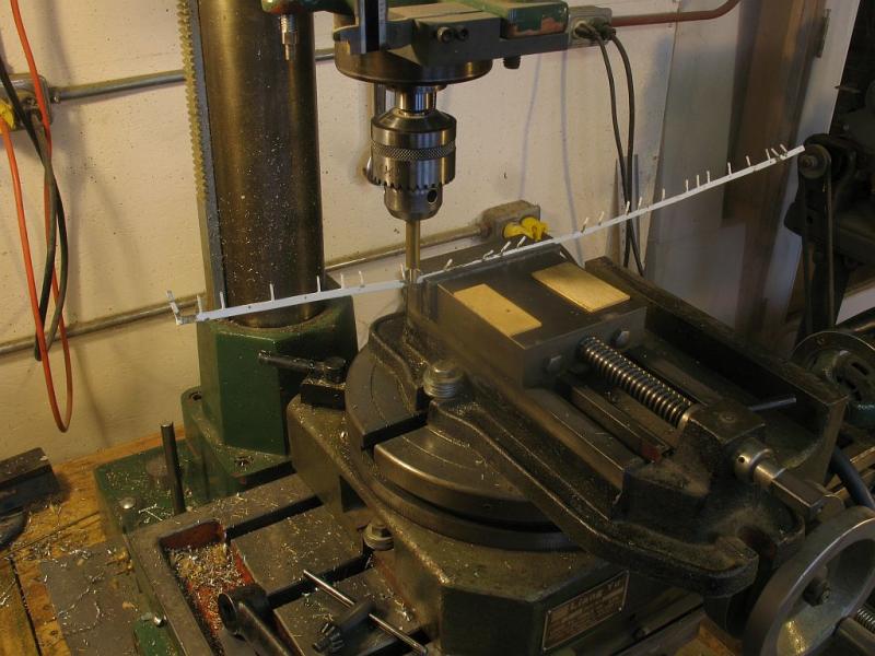
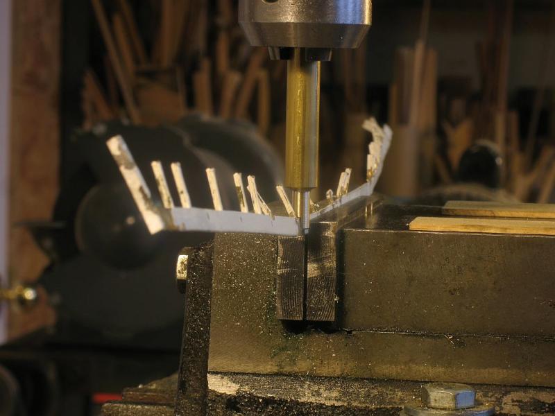
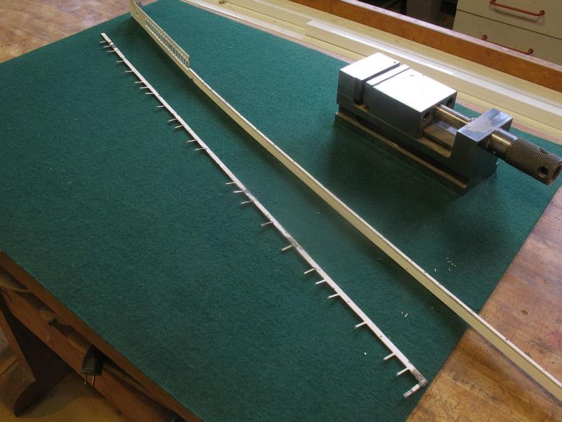
Thanks Nils today I spent some time straightening out the twisted port side sheet metalwork immediately below the boat deck. I used a combination of finger pressure and used the mill drill as an arbor press. I made a small brass yoke for the job. By using the wide mill vice I was able to flatten most of the rotated twist Then using the yoke I was able to take out the kinks that were in the vertical direction. I am going to clean it up I noticed that the paint flaked off easily as if there was no primer on the raw metal. The next task was to make some special clamps so that the boat deck can be re-glued to the ship. The deck is curved following the lines of the hull so the infrastructure will need to accommodate this aspect. The first part was to make a clamp fixture that attached to the hull, these are large U shaped wood pieces that are covered with 1/8th felt on the bottom and the starboard side to give a large contact on the base and starboard sides. These U shaped clamps have a 3/4 x 3/4 angle attached so that a horizontal bar can be adjusted to match the elevation needed for the boat deck. The horizontal bar will get some additional elements that will form a series of supports under the boat deck. I am still working out the best way to accomplish this The bar is locked with some 10x24 screws Michael


- 749 replies
-
- 18
-
-
- albertic
- ocean liner
- (and 2 more)
-
Igor you are insane What an amazing way to capture a sense of drama. The boat passing the lighthouse rocks nearby a shift in the wind all was ok. Wonderful piece of modelwork.
- 22 replies
-
- 2
-
-
- jolie brise
- diorama
- (and 2 more)