gak1965
-
Posts
727 -
Joined
-
Last visited
Content Type
Profiles
Forums
Gallery
Events
Everything posted by gak1965
-
 Well, at a minimum you can say that chipped paint would have been realistic for the ship in life . I had vaguely thought about getting this as a 'simple' project to have going once I start the Discovery, I'm a lot less certain of that now. Keep it up, I know you'll get there. George K
- 113 replies
-
- 5
-

-
- Cairo
- BlueJacket Shipcrafters
- (and 1 more)
-
I believe @MrBlueJacket called it "hours of fun"
- 602 replies
-
- 3
-

-
- Flying Fish
- Model Shipways
- (and 2 more)
-
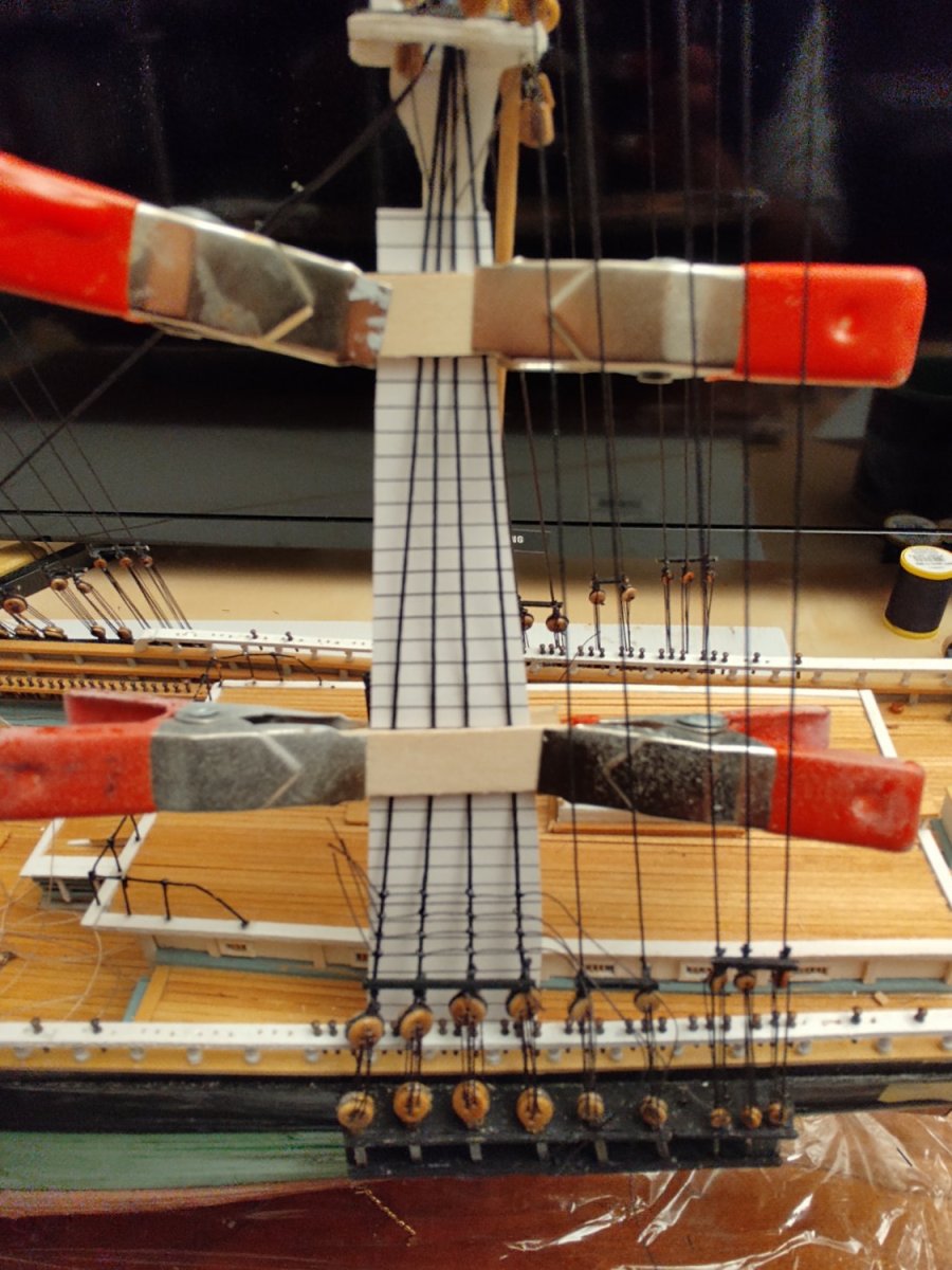
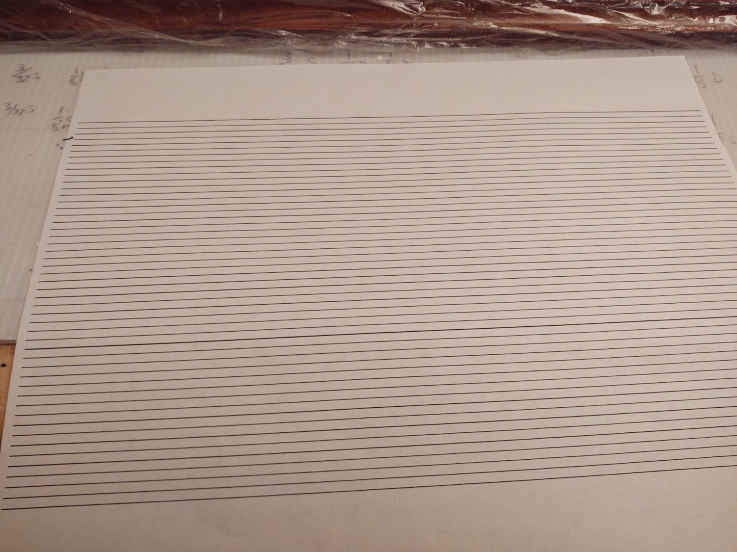
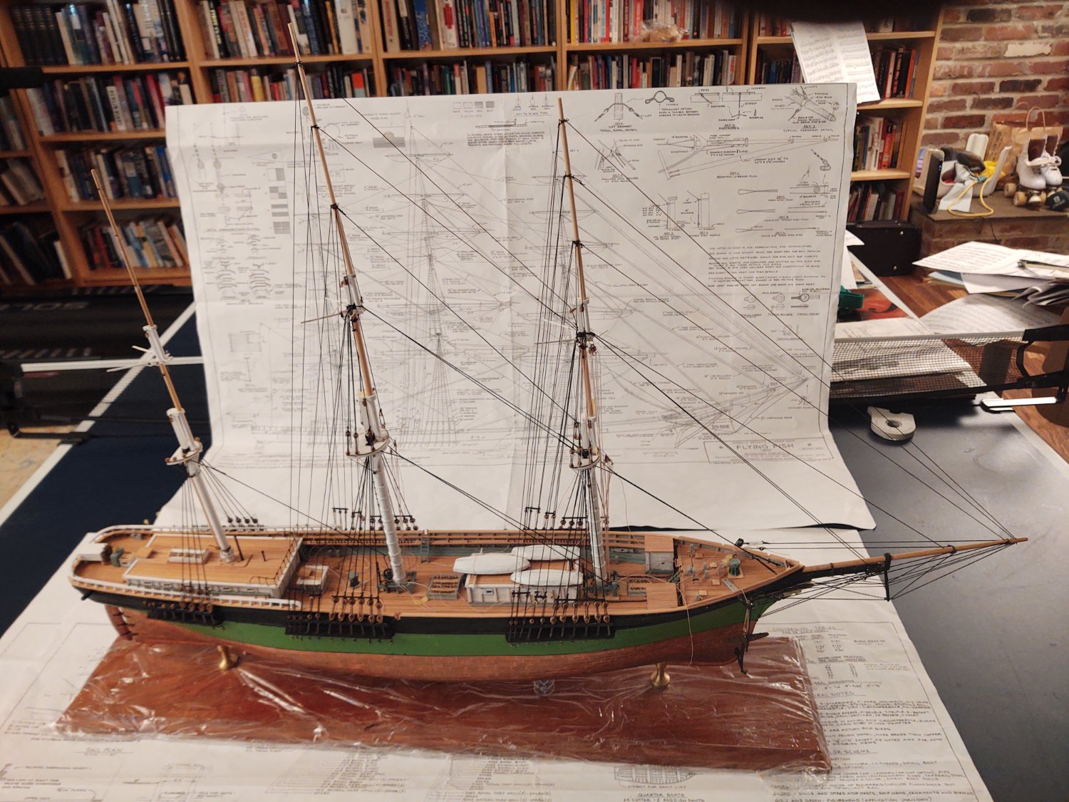
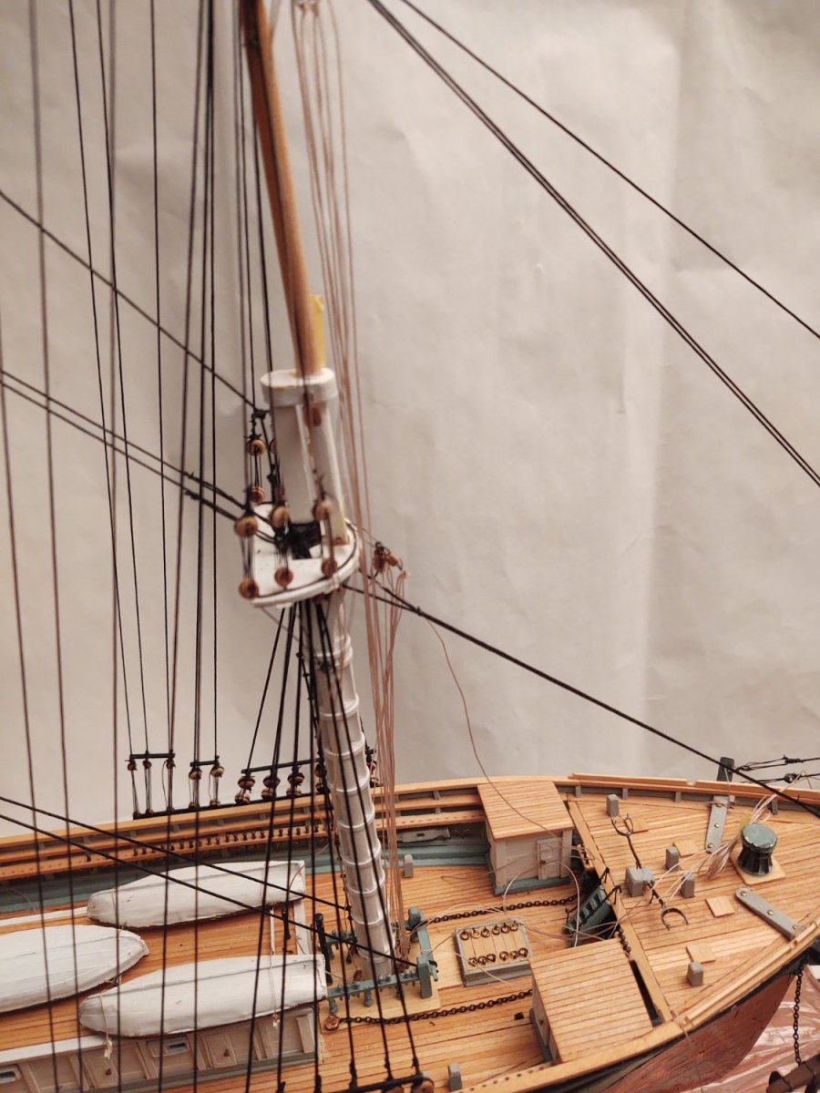
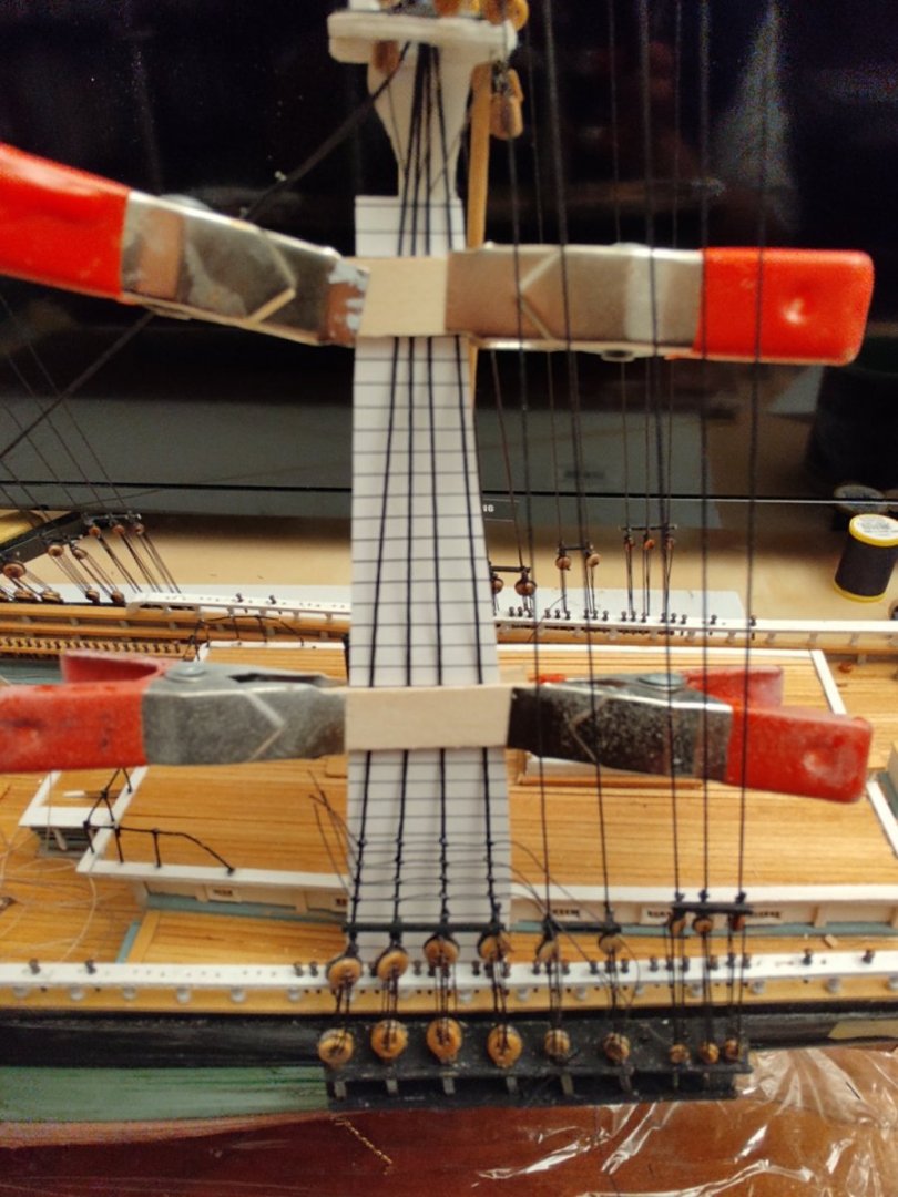
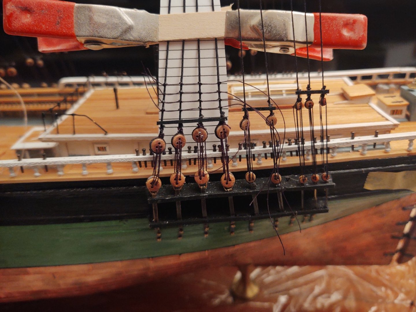
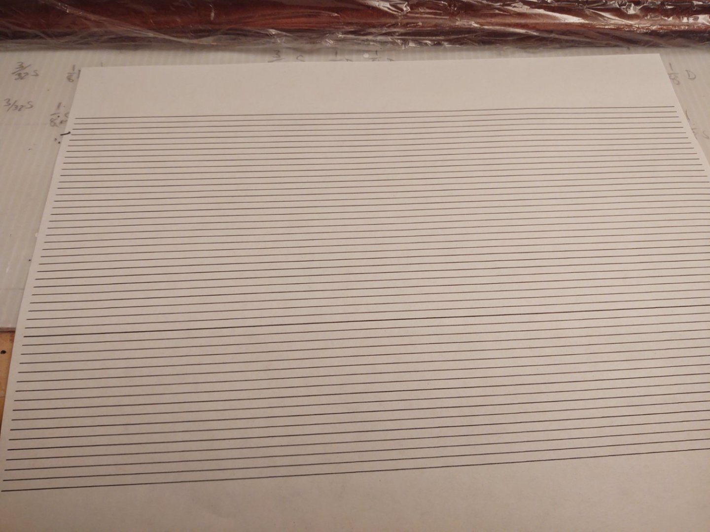
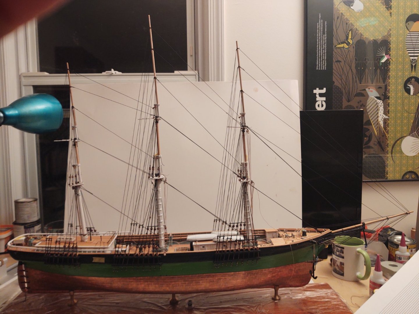
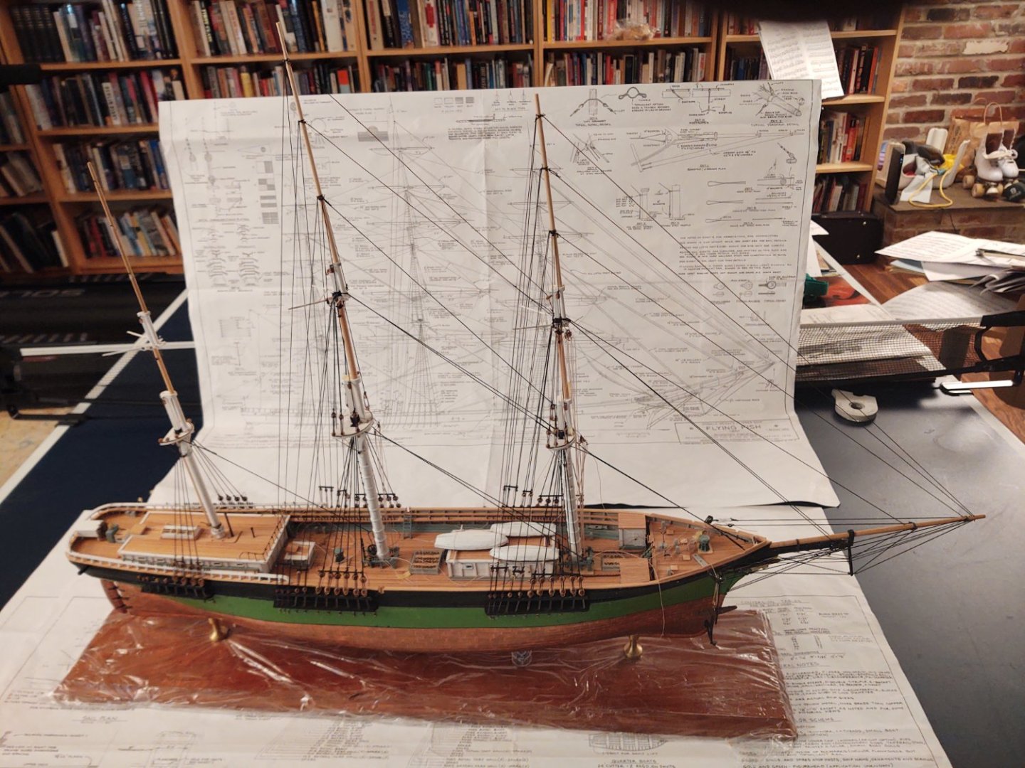
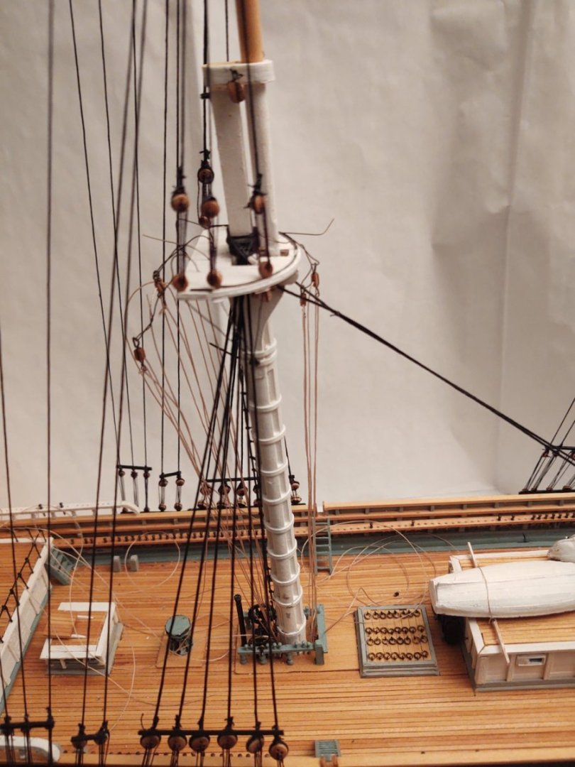
Well, "one week" of effort appears to have been more like 17 days, but the mizzen is mounted and rigged. This is the end of the standing rigging (except the ratlines), and actually, there are 12 clew tackles installed, so I guess the running rigging has been started. The mizzen is relatively clear since there are no fife rails, and rather than have the lines in place cluttering things, I haven't installed them there yet. Now for the ratlines. I intend to make the yards and supporting hardware (e.g. trucks, gin blocks) while tying the ratlines. That way if I do 5-10 lines (20 - 50 knots) per day, I should be done with them in a month or so. At 1:96, 15" is 5/32 inch, so I made a sheet of lines with that spacing in PowerPoint and printed it out to use as a guide: I attach that at the top (I'm working on the lower port mizzen shrouds, now) using clamps and two pieces of scrap wood. The similar feature toward the deadeyes is to try to keep the shrouds from compressing in - I'll move up as I move up the shroud. The above photo makes it look like they aren't very straight, but as can be seen below they aren't bad at all, if I do say so myself. The knots are simple overhand, stabilized with a bit of glue. I find that anything larger (a) starts to get very big and out of scale, (b) puts more strain on the outer shrouds, contributing to the squeezing in, and (c) is radically more difficult to set up with the proper distance between the knots. Anyway, I hope everyone is having a good year, and thanks for looking in. George K

- 602 replies
-
- 7
-
-
- Flying Fish
- Model Shipways
- (and 2 more)
-
Just my $0.02 here, but if you overcut the bottom, is it really that much of a problem? Mount the "armor", fill in any bottom gaps with putty, then glue the whole thing on the deck. Looking good and I'm sure you'll find something that works. George K
- 113 replies
-
- 5
-
-
- Cairo
- BlueJacket Shipcrafters
- (and 1 more)
-
Just found your log and it's looking great. Two quick observations from someone who has built the Niagara kit. First, buy a lot more of the small eyebolts. I don't know what they were thinking; I wound up ordering 240 additional eyebolts in order to finish. Maybe they didn't include the bolts needed for the jackstays, or perhaps I missed something, but I went through those things like there was no tomorrow. The other observation is that all Model Shipways kits (I'm on my third) don't ship all of the line diameters indicated on the plans; this is also true with regard to deadeyes, bullseyes, wire, etc. The plans are frequently of the ship, rather than the model, and then the kit has a subset of the needed sizes. Not looking to beat up on Model Shipways - I like the fact that they are "semi-scratch", you really get to build skills - but I always wind up with a pile of leftover wood and having to order a bunch of things that fall into the 'fittings' bucket. Good luck going forward, George K
-
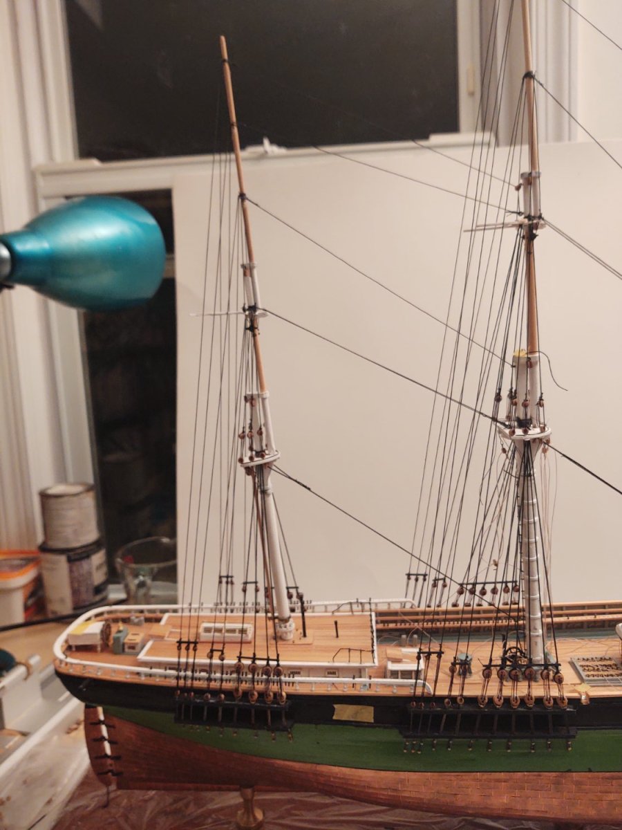
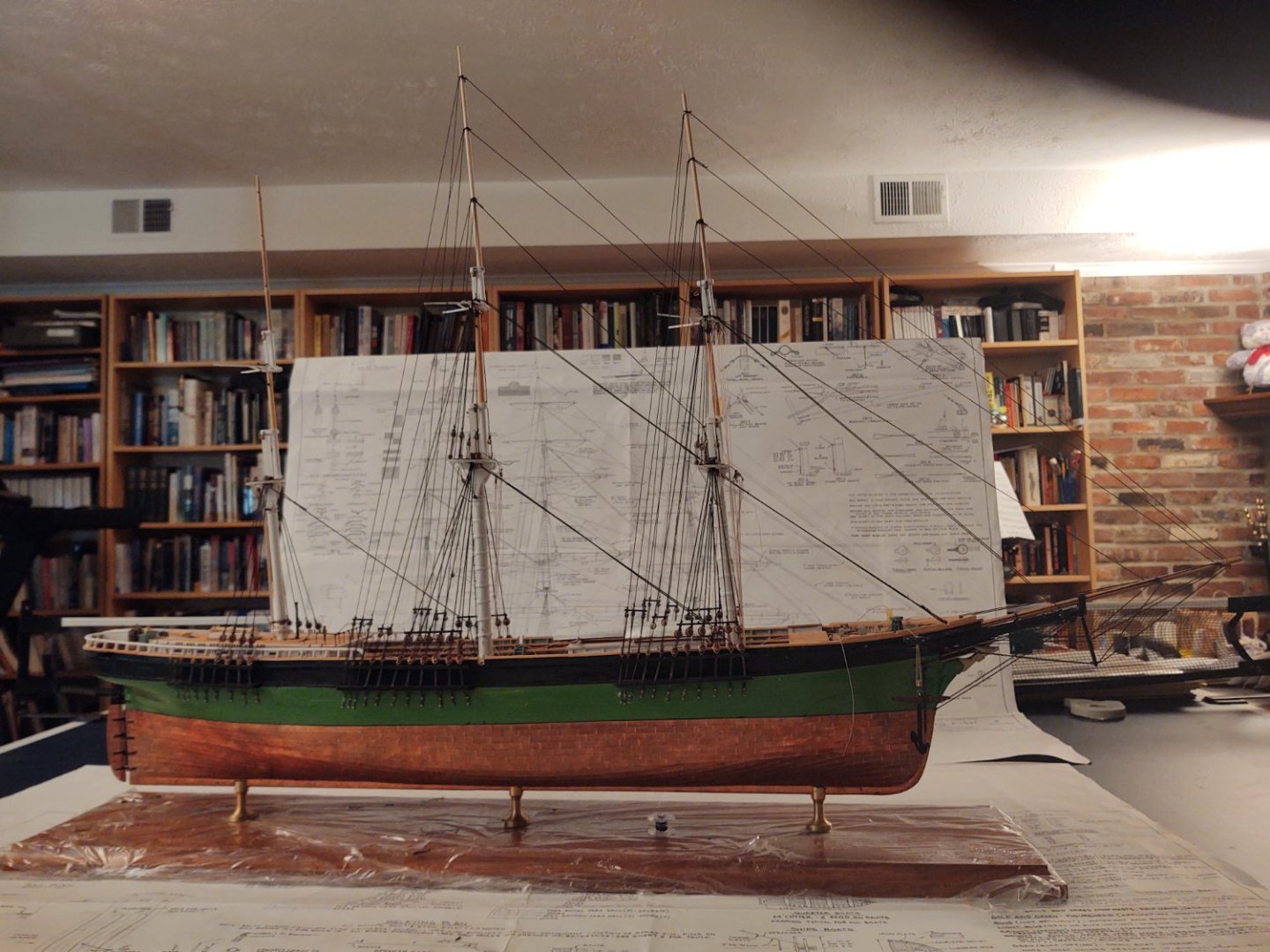
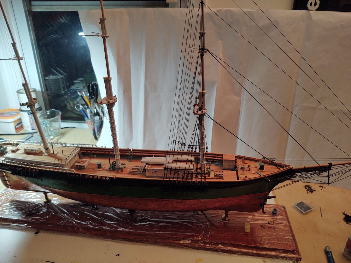
Well, it's the end of the year, so here is the Fish as of the end of 2022. The mizzen is mounted, and the lower mast rigging (shrouds and forestay) are in place. I need to make two more gin blocks before fitting the topmast and topgallant shrouds and stays, but shouldn't take more than a week to get to the point where the standing rigging is done except for ratlines, at which point I'll start making the yards while getting them done. Have a safe and happy New Year. George K

- 602 replies
-
- 6
-
-

-
- Flying Fish
- Model Shipways
- (and 2 more)
-
@Snug Harbor Johnny good luck on the Thermopylae. Hopefully the Revell directions (particularly the rigging instructions) will be as good as those they ship with Connie even if getting into the spaces was challenging. George K
- 602 replies
-
- 1
-
-
- Flying Fish
- Model Shipways
- (and 2 more)
-
Thank you. I saw that you had finished the Egyptian boat. Are you thinking a clipper next?
-
Thanks. Mike R was the man with the notion of starting at the mizzen (which is not what the instructions suggest). My last build was the Niagara at 1:64 and the combination of two masts and the extra space meant it wasn't a big deal to start forward, but boy does it matter her.
-
Thanks Rick. Re. the Butterworth painting, barring new data it's going to be impossible to ever really know. I think there are 5 active Fish builds now (yours, KeithBrad80's, Jared's and my Model Shipways kits) and Rick310's 1:64 scratch model from the same set of plans. It would be interesting to set them up side by side some day and see the specific interpretation differences. For instance, I included the cutwater and naval hoods that aren't on either the plans or the Butterworth painting (but which Clipperfan has convinced me must be there), but I left off the mast hoops on the mizzen and kept the cabins pretty much as per Ben Lankford's plans (well, and I painted it green per a note in Stephen Ujifusa's book Barons of the Sea that McKay wanted to paint her that color). Like I say, it would be cool to do a side by side. Maybe once we are all finished, we can do a series of 'standard' photos and create a small gallery called 'Varieties of Fish' or some such. Hope you had a great Christmas/Hanukkah, and have a safe and happy New Year George K
-
Really nice looking deck house. I love the interior rooms
-
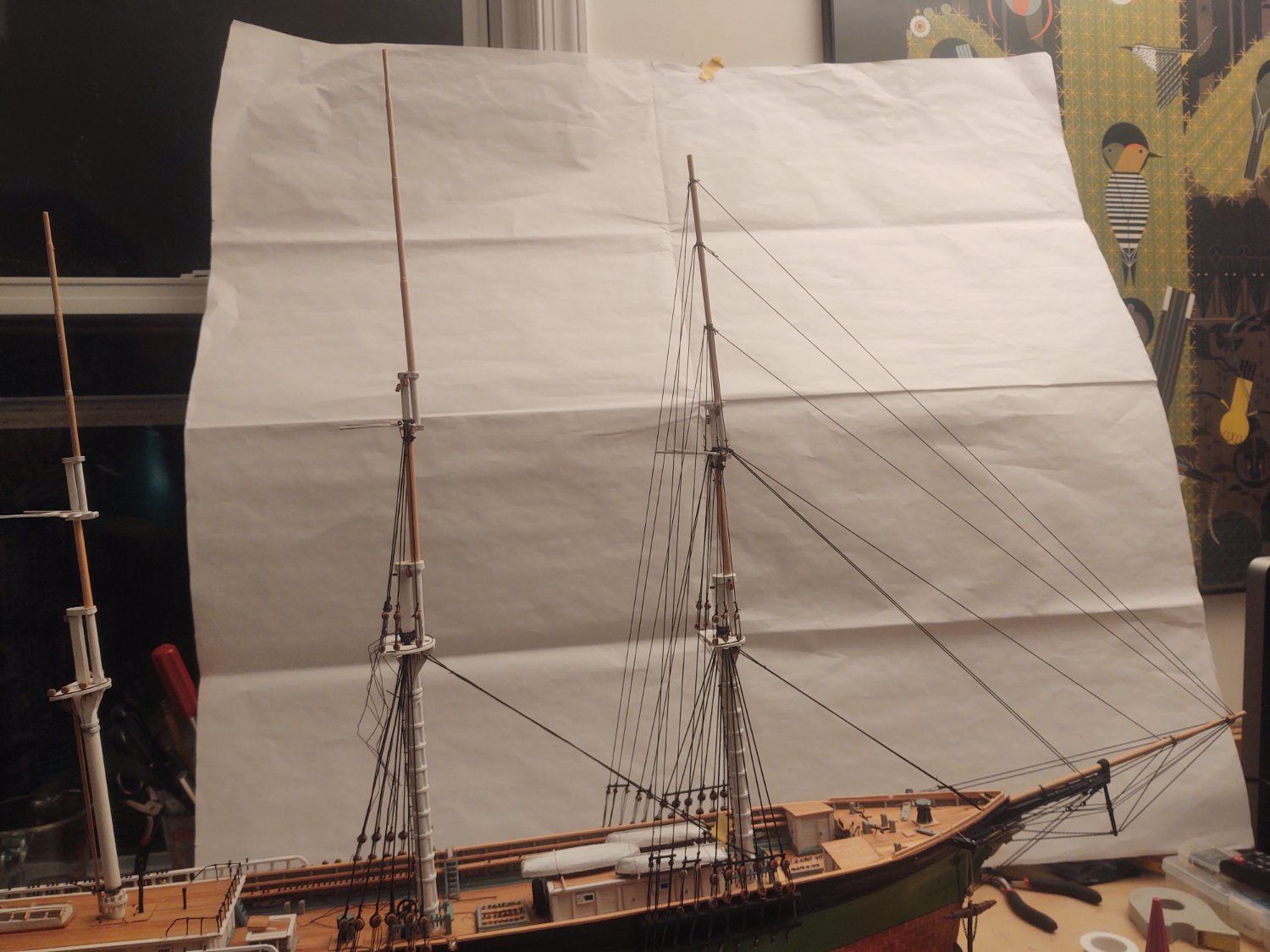
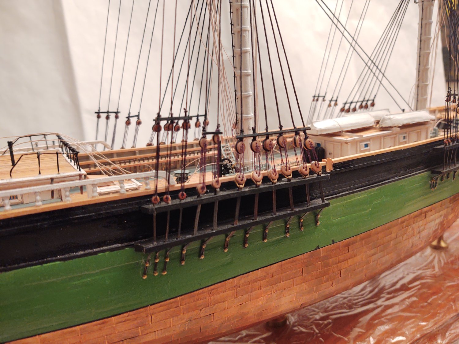
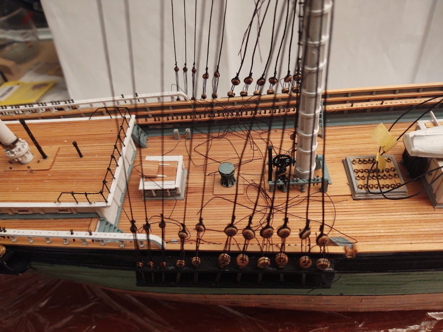
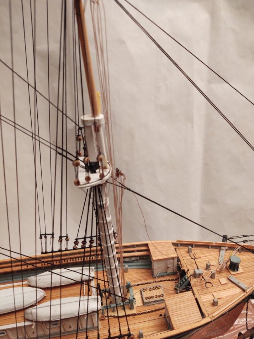
Well, almost a month since my last update, but the standing rigging on the main mast is done (well except for those pesky ratlines, but who counts those). Thanksgiving, visiting my younger daughter in Boston, a multi-day all hands at work, Christmas|Hannukah shopping, lights, and catching some sort of nasty cold|flu (but not COVID) definitely slowed the pace of progress. I used the same strategy as before, getting everything in place but not anchored, and then tightening from the top down. As before, the only lines that I did not do that on were the topgallant shrouds - and in that case because they really weren't impacting how the mast moved in three dimensions. The first couple of pics just show the mast and the lines going up: And all the lines that were starting to become quite the mess on the deck: And here are a couple of photos of the mast with all the lines in place. One of the sheer poles on the port side looks a little odd in the photos, but it's a trick of the angle thing - looks fine on the port side itself, and looking at the pictures, I think that the folds of the paper I have to provide some contrast are making the skystay look a bit weird too. And a close up near the bulwarks: You may have noticed a bunch of tan lines in the photo. As I indicated I would, I mounted the clew tackles for both the main and fore masts because they are attached to the deck via eyebolts that are inside the fife rails. It was a pain in the posterior now, it would be worse once the ratlines and/or other running rigging (or yards for that matter) were in place. A couple of pics of them with the attachment points to the clew chains hanging out of the way: Well, on to the mizzen. One thing that I have found is that if I was starting over from scratch I would follow @MikeR's method and rig from the mizzen forward. Having the shrouds and backstays in place makes it 20 times harder to lash the stays in place, and his method keeps all of that clear until after the stays are in place. As always, thanks for looking in, and if I don't post again until after the holidays (gonna try to get one more in 2022, but you never know) have a happy holiday season, however you celebrate and a good 2023. George K


- 602 replies
-
- 3
-
-
- Flying Fish
- Model Shipways
- (and 2 more)
-
One thing I've learned as I've been working on my fish is to do it your way, mizzen to fore. Access to the anchor points for the forestays looks like it will be much easier that way. Your ship is looking fabulous and I can't wait to see it progress.
-
Wow. You can take a dry dock tour of the Texas. Pretty awesome. https://battleshiptexas.org/drydock/
-
Gonna use this method on the Fish, especially starting with the triangle rather than trying to carve from a solid piece of wood
-
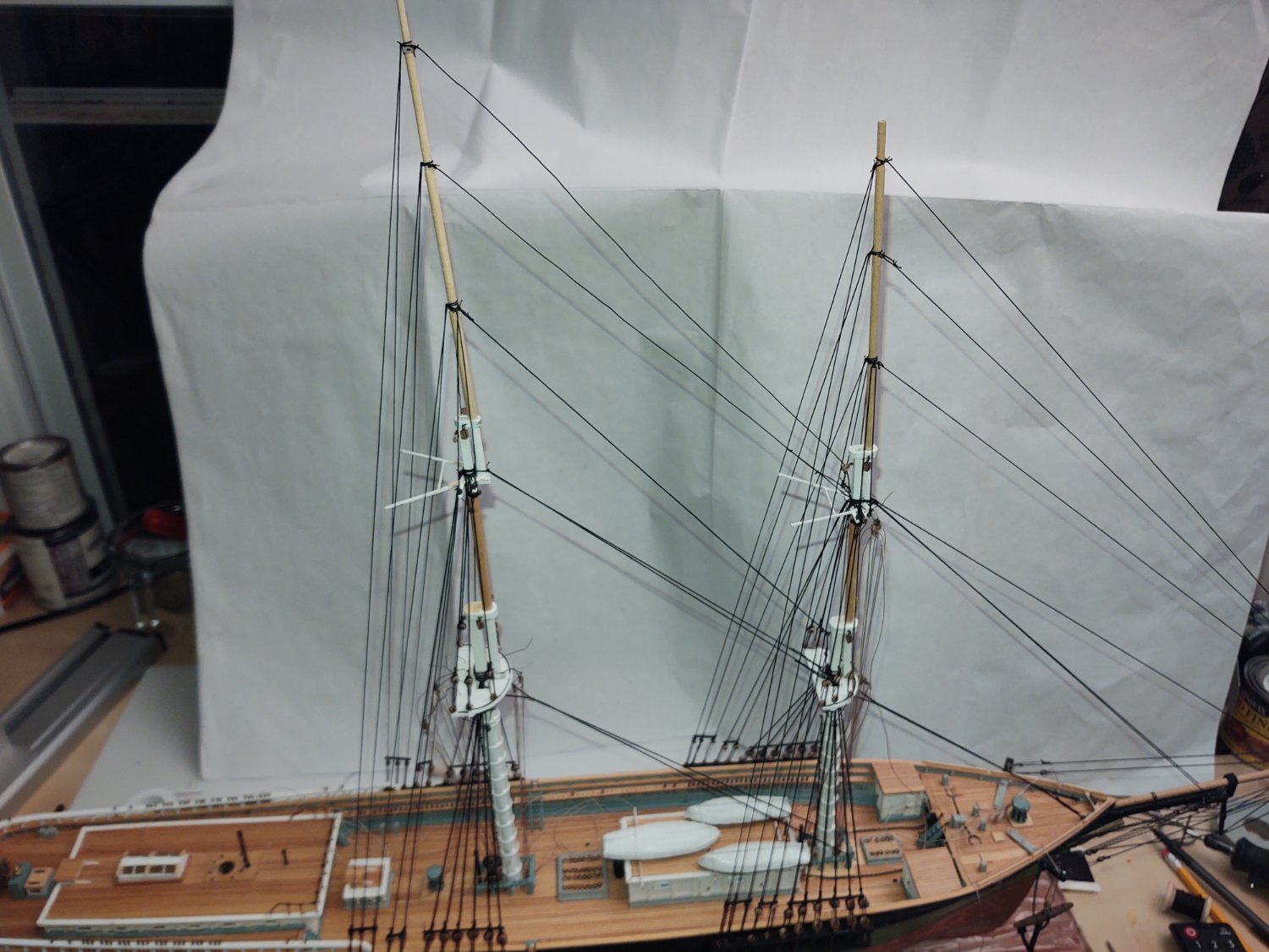
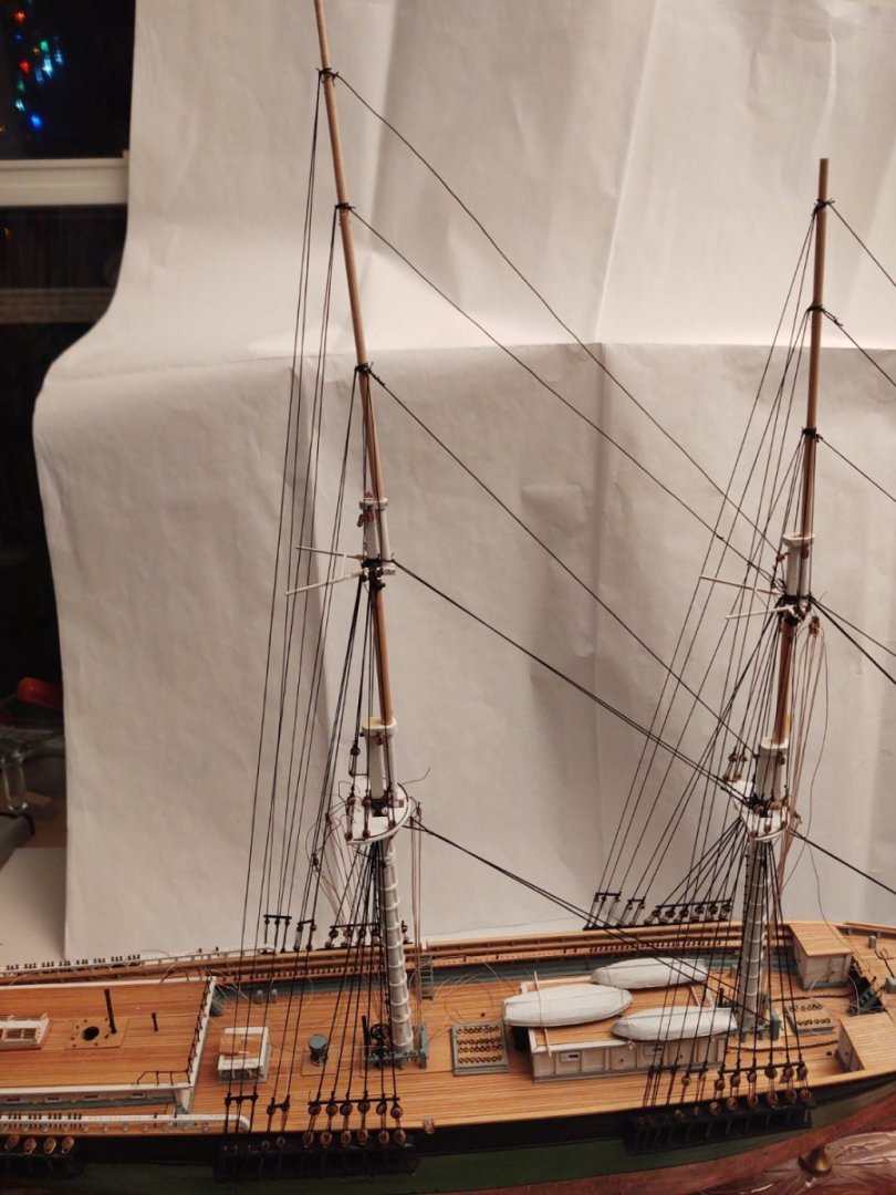
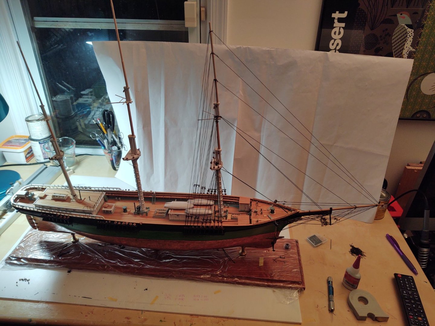
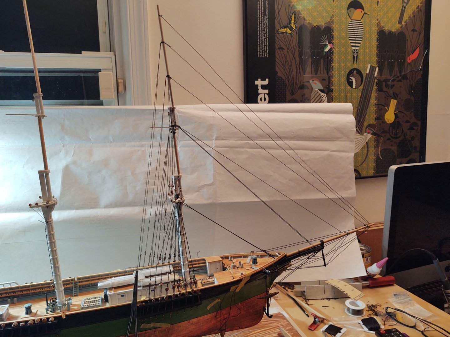
Well, it's been 12 days since my last update. I wished I could say that I have made massive progress, but I think I will have to settle for some progress. At this point, all of the mainmast futtock shrouds are in place, and I've rigged (but not anchored the lanyards) of the lower and topmast shrouds and the main forestay (which terminates on the foremast fife rail). As with the fore, I'm going to get all the lines in place and then tighten/anchor from the skysail down. Here are two pics of the main and foremast as things are moving along. One thing I am thinking about doing before starting the 'fun' of the ratlines is attaching the tackles (I think mostly halyards) that terminate on deck around each of the masts. The six tackles on the mizzen should still be relatively clear since there isn't a fife rail blocking access, but I'm guessing it's not going to get easier to access after the ratlines are in place. Thanks again for looking in and have a Happy Thanksgiving! George K.

- 602 replies
-
- 4
-
-
- Flying Fish
- Model Shipways
- (and 2 more)
-
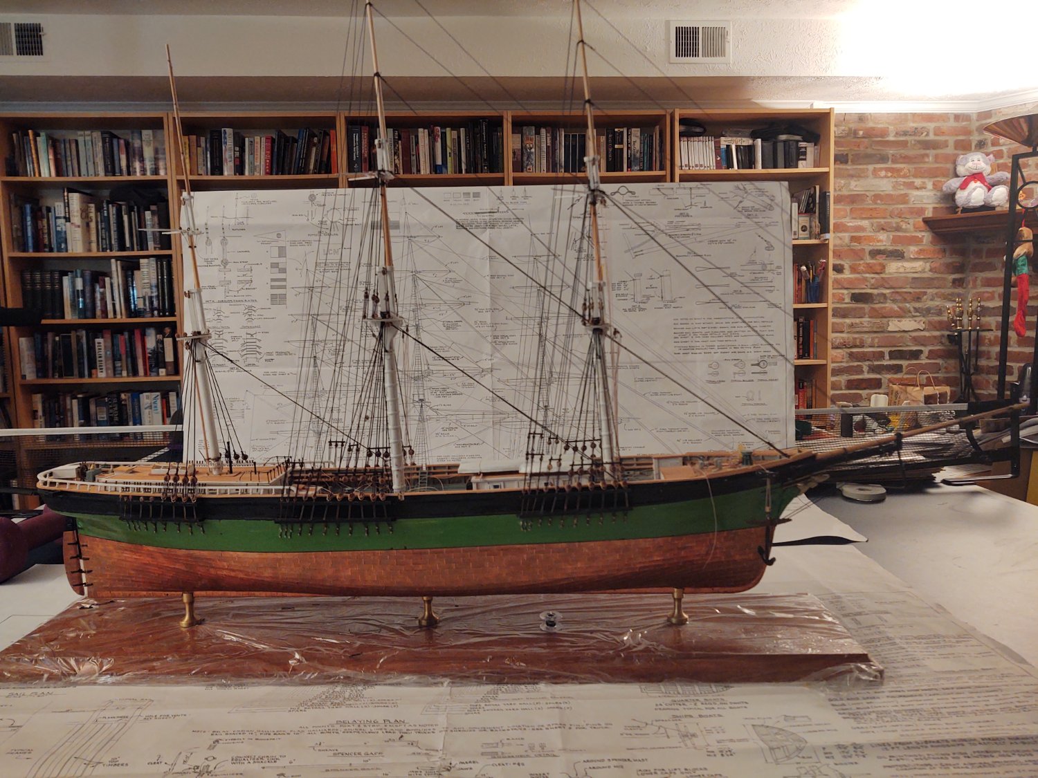
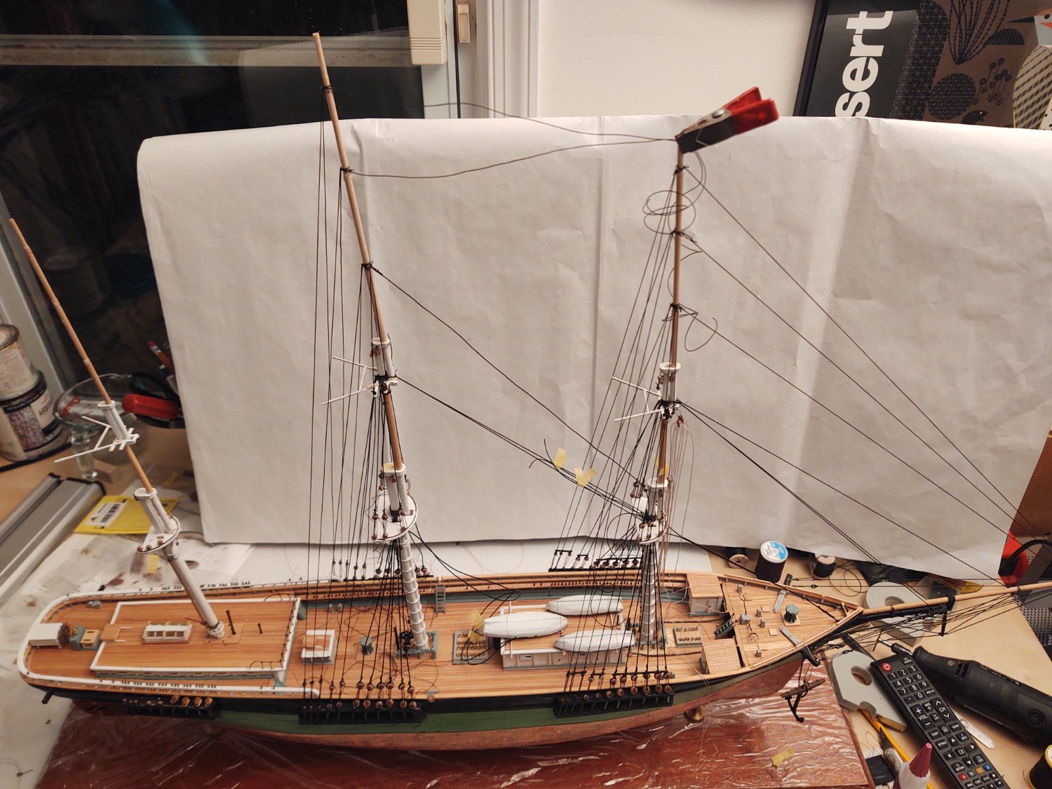
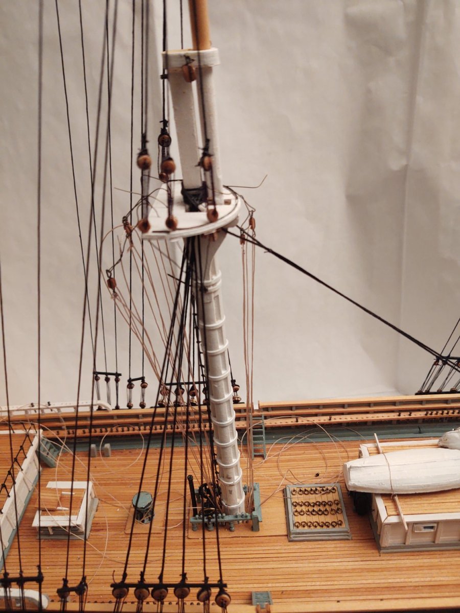
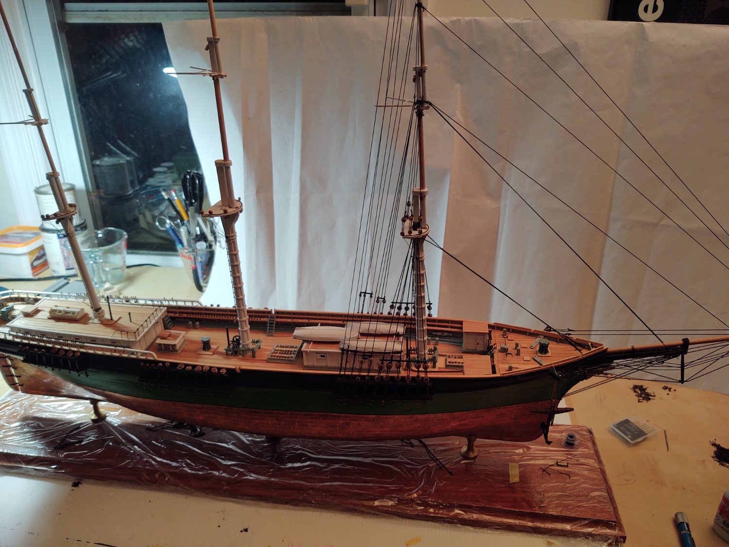
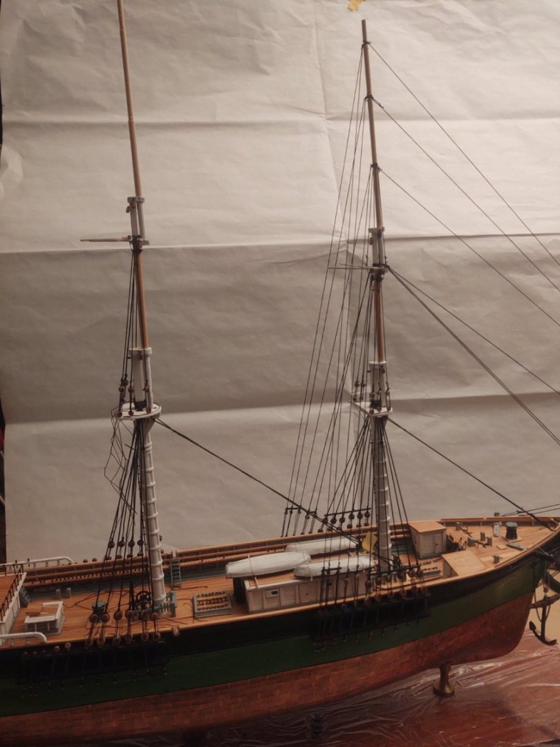
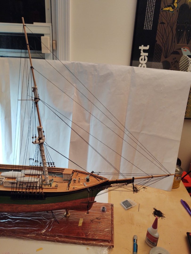
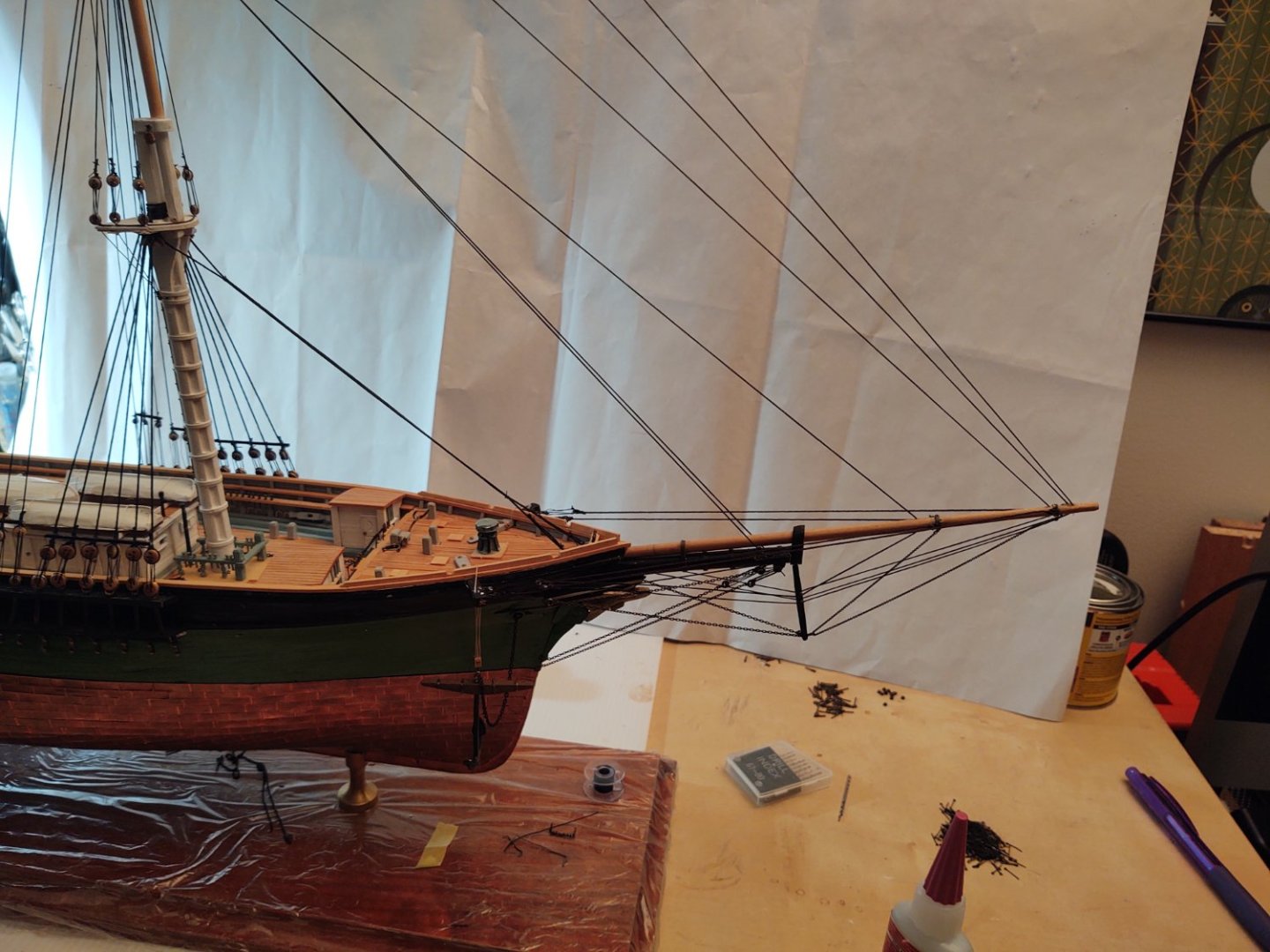
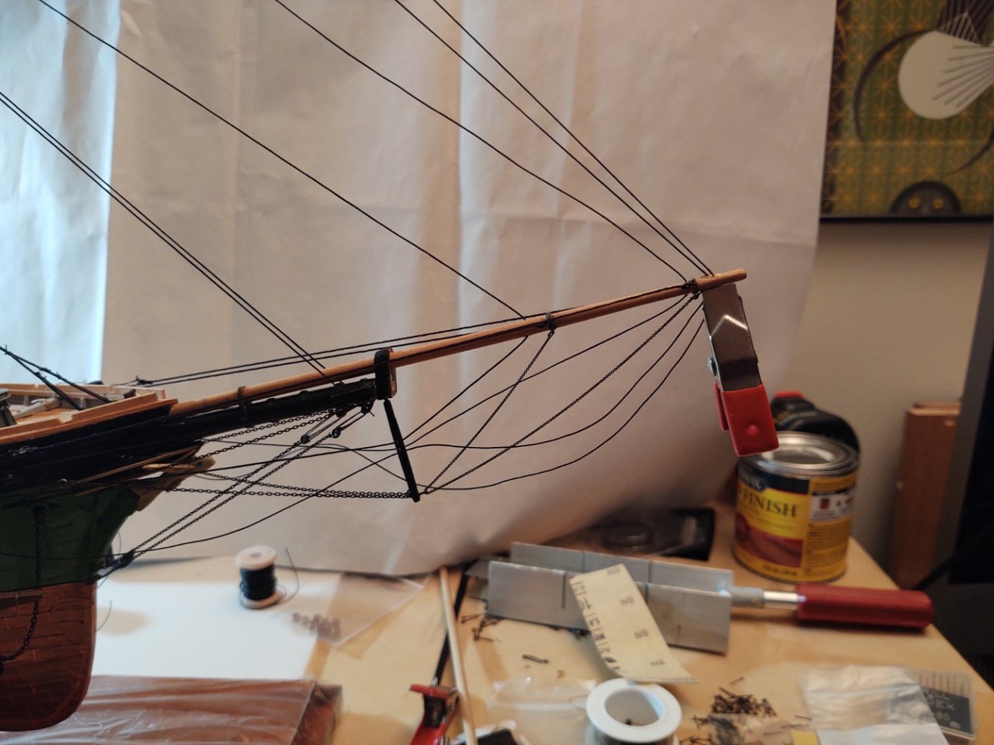
Hello all! First of all thank you for the encouragement, it is much appreciated. I really enjoy looking at so many of your builds on MSW, without which I suspect several builds would have gone into long term storage rather than move forward. Well, the standing rigging (minus those pesky ratlines) is now complete for the foremast. Nothing earth shattering here from a technical perspective, basically just lots of tightened lanyards and anchored lines (and a 6 sheer poles). As per a couple of posts back, I did anchor the hull ends of the topgallant-, royal-, and skystays into a hole in the bulwarks after also gluing down their paths in the jibboom and on the dolphin striker. It may be a problem in 50 years (dunno how long these adhesives really last), but I'll be long gone at that point, so... One other thing, which we don't talk about as much as we should I suppose; in the process I (a) broke off one of the figureheads wings, (b) disconnected the bulwark end of both of the bowsprit shrouds (the chains) and (c) caught the tip of the mainmast in my watch band, requiring a minor repair to the base of the mast. <SIGH>. Anyway, nothing that couldn't be fixed with a little CA glue. Completely par for the course. Anyway, here a couple of photos of the ship as it currently stands, some closer views of the foremast and all the bowprit rigging. As always, thanks for looking in! George K Sorry my photos are often not perfect - I tend to work at night so the light can get weird. I have started putting one of the plans over the TV set I have on my worktable so that you can see the lines better.
- 602 replies
-
- 6
-
-
- Flying Fish
- Model Shipways
- (and 2 more)
-
It is, although I find it interesting that the Yamato is only 12 meters longer overall (5% ish) and 2 meters beamier (5.5%) but yields a full load displacement 36% larger (even higher if you go standard).
-
Um, I noticed that the work is awesome 😎! What else is there to see.
- 399 replies
-
- 2
-
-
- cutty sark
- revell
- (and 2 more)
-
Thanks all. I should probably just take the above and say 'of course', but the reality is much more mundane. I wasn't thinking about strain from the main stays, but rather about forcing the fore topgallant/royal to be at the same angle as the main. So, more fixing a defect in my mast manufacturing than thinking ahead. Not that this would be out of line at all for a real ship, but it's a bug, not a feature.
-
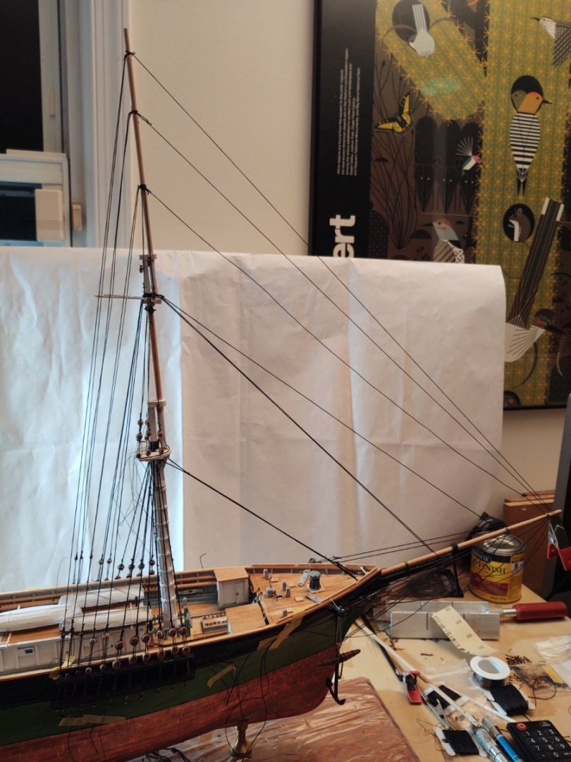
Progress on rigging the foremast. This photo shows the lines going up the foremast according to the plan order (generally lift pendant, shrouds, forestay, backstays). As I mentioned last time, the only place anything is anchored is on the mast, the lanyards and the line ends are all basically held in place with Tamiya tape (or in some cases, just the tension in the deadeyes. In the next photo, I've started to anchor lines, beginning at the fore skystay. The logic here is that I want to pull the top of the foremast forward about 3-5 mm so that it will align properly with the main. To do that I started by clamping the skystay under the jibboom after pulling the mast top forward appropriately. I then put a drop of CA glue into the hole with the stay and let it set. This stabilizes the line where I need it to be, and I can tighten and anchor the fore sky backstays so that the mast is properly centered and we have a reasonable amount of tension on the skystay so everything stays neat, as below: Next start moving down the mast. so the royal stay has been tightened and a bit of glue to hold it in place. Once it sets, I'll do the royal backstays, do the topgallants. When I get to the topgallants, the order is going to be stay, backstay, shrouds, and the last items to be tightened will be the lower shrouds. At that point, I'm hopeful the the lower forestay won't be sagging, but if it is, I'll just tighten it down. One thing that I have concluded is that I should actually be able to anchor the forestays into holes in the bulwarks, as per the plans. I was worried that the amount of strain would wind up making that a problematic means of anchoring, and thought I might anchor into an eyebolt instead, but it appears that a drop of glue on the jibboom/bowsprit, one on the dolphin striker, and a third one in the bulwarks should be just fine. The only case where that might not work are the two stays that go through the bees, but even there, two glue spots (bees and bulwarks) should be just fine. As always, thanks for looking in! Regards, George K
- 602 replies
-
- 10
-
-
-
- Flying Fish
- Model Shipways
- (and 2 more)
-
1/200 Trumpeter IJN YAMATO - issued by MRC/Gallery Models
gak1965 replied to yvesvidal's topic in REVIEWS: Model kits
I'm with Yves here. The difference on a sailing ship between 1:96 (say the Revell Connie) and 1:150 (the Heller Passat) is obvious and that's slightly less significant than the difference between 1:200 and 1:350. I remember wishing the Passat was 1:96 as well when I had to anchor multiple lines in constricted spaces even if it would mean a ship 1.1 meters long! Ultimately, nothing is going to beat the impact or detail of a high quality, large scale model. Compared to 1:350 (or the old "box scale" kits I built as a kid) it gives you a sense of the size of the real things. I suspect that for the largest ships we've hit the limits of how big you can go on the commercial market, but I could be wrong. My grandfather's Nichimo Yamato was displayed (back in the 60's to the 80's) in a long window we had in our rec room and first time visitors always gravitated to it, I expect the same will be true for you. All four will ships will be a challenge, but I'm sure you'll find a place. I have a similar problem as I have to figure out what to do with the Flying Fish I'm working on now. I gave my parents my Connie, the Passat is in my wife's home office, Pride of Baltimore in the sun room, and I have the Niagara in mine. Not a lot of room and these sailing craft take up a lot more vertical space, so I don't think I'll be able to stack the cases for the Niagara and the Fish. Regards, George K- 104 replies
-
- 2
-
-
- MRC/Gallery
- Yamato
- (and 1 more)
-
Obviously your opt, but I can tell you I've seen well done OoB Nichimo Yamatos and they are still great looking, reasonable representations of what we think the real ship was like (there are questions, the Japanese government destroyed a lot of the info about her and the Musashi at the end of the war). Add the PE, it gets even better. At the end of the day you are edging into a philosophical question about what simplifications and omissions (all models have both) is best, and there may not be an obvious answer. Is some additional level of accuracy around hull lines or armament, or whatever worth replacing the investment you've already made? That's yours to make and to heck with what anyone else thinks! Enjoy either way, it's the journey that makes the whole thing rewarding. George K