gak1965
-
Posts
608 -
Joined
-
Last visited
Content Type
Profiles
Forums
Gallery
Events
Everything posted by gak1965
-
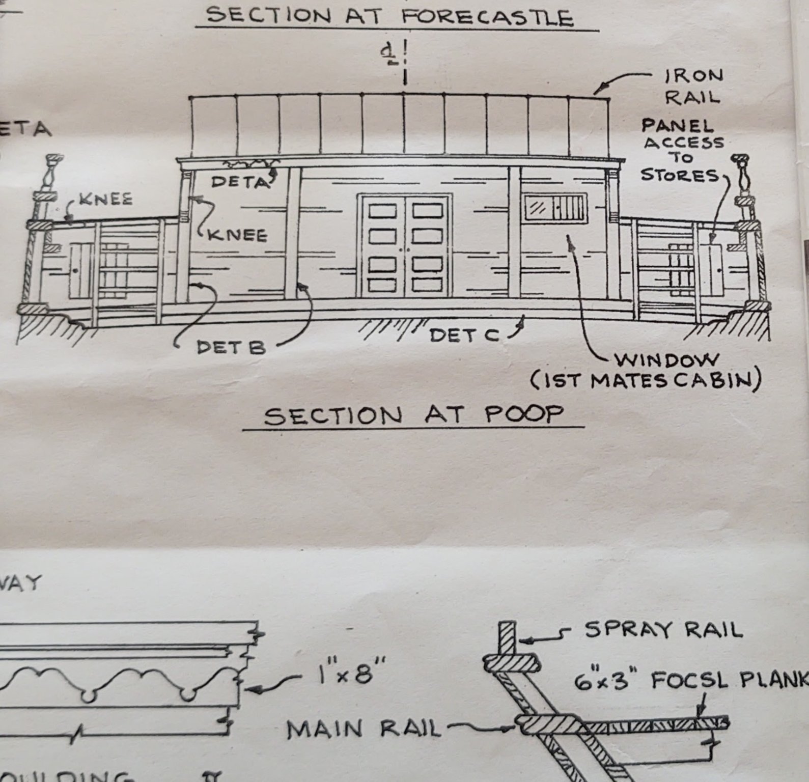
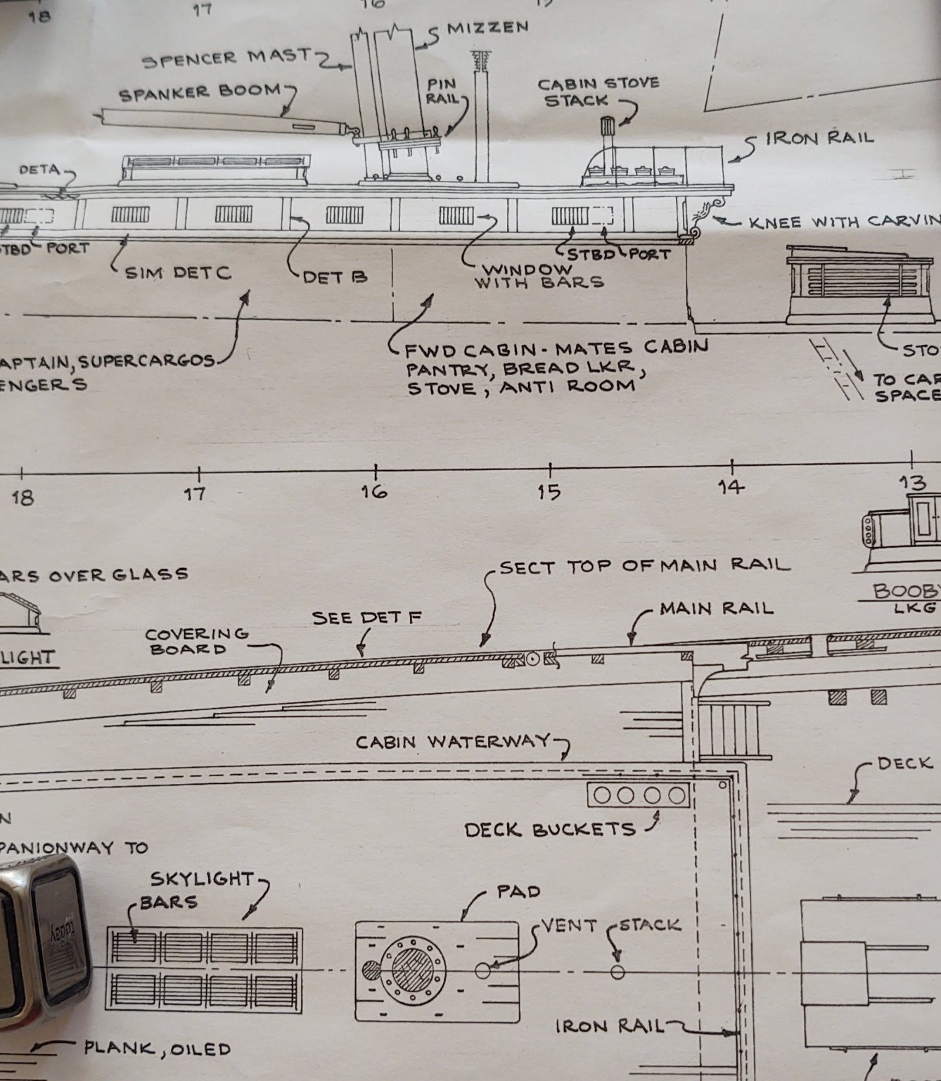
 So - a quick question to all you experts on McKay clippers, seeing as I am really having a bit of trouble converting the plans into a constructed structure on the poop. Below are two segments of the Fish's plans. The first shows the poop looking aft, the second shows side and above views of the transition from the poop to the main deck. Okay - so what I do know - the overhead of the poop cabin extends over the main deck, where it has some decorative elements including an elaborate knee. So far so good. Where I am confused is this. If you look at the aft facing view, you can split the area into three segments, two half height sections toward the bulwarks and a center section that is full height. If I read the set of diagrams, it would indicate that the half height segments are built up from the coaming to the edge plank on the poop, with the edge plank overhanging the bulkheads that make up those half height sections (i.e. from aft to forward, you have the forward side of the bulkhead and then the forward side of the poop edge plank. The center, full height section appears to sit completely forward of the edge plank on the poop, which suggests that it is pushed out slightly compared to two half height sections. And it may require a wider coaming at the center than at the edges (need to see exactly where the coaming sits when I install it). Is that correct? That seems to be the configuration that is on Rob's @rwiederrich Glory of the Seas, and it seems to be a McKay feature, but thought I would put the question out to anyone that has build the Fish or done research on McKay clippers (e.g. @ClipperFan or @Vladimir_Wairoa). Thanks in advance, George K.

- 600 replies
-
- 1
-

-
- Flying Fish
- Model Shipways
- (and 2 more)
-
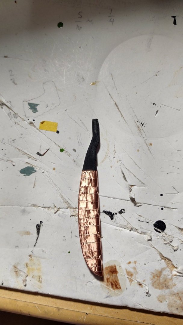
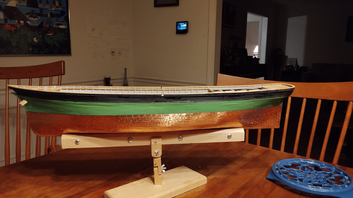
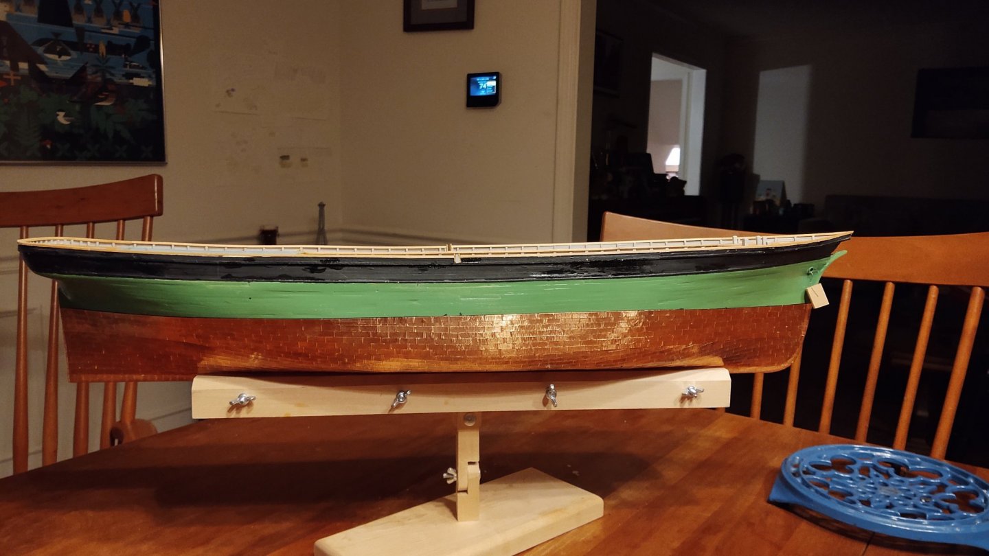
Just a brief update (it's been a crazy couple of weeks without much time to build). Rudder removed, shaped, sanded and coppered: 5 hinges made and rudder attached to hull: The gap between the rudder and the hull is a bit more than I would prefer, but it was a tradeoff between having some detail in the hinges and having the rudder closer (I can't seem to make hinges that are much less thick). So, yes on the detail, let the chips fall where they may. Thanks for looking in! Regards, George K

- 600 replies
-
- 4
-
-
- Flying Fish
- Model Shipways
- (and 2 more)
-
Thank you. And definitely going to let it patina. Not the least of which because it will disguise the obvious fact that it isn't the color of Muntz metal. I thought about the spray paint option, but chickened out.
- 600 replies
-
- 1
-
-
- Flying Fish
- Model Shipways
- (and 2 more)
-
Thank you and I appreciate the insight into the original version! If you are ever in Portland, it's worth stopping at Powell's books, as they frequently have wonderful used editions of books on sailing ships. Last time I was there (my younger daughter was in college in Portland until she transferred last year) I came this close to buying a copy of a three volume history of clippers published around 1920. Still not sure why I didn't, but water under the bridge as it were. FWIW, I am the antithesis of an artist, which is why I enjoy looking at so many of the builds on this site. I remain in awe of the people that can create such beautiful effects with paint or other drawing material, and I find it a useful inspiration, something to swing for, even if I don't reach those standards. At least they focus me to strive for my best. Warm regards, George K
- 600 replies
-
- 1
-
-
- Flying Fish
- Model Shipways
- (and 2 more)
-
The Dover edition that I picked up at Mystic (which is listed as an unabridged version of the 1928 text) is renamed for reasons that I don't understand. It has the diagrams and paintings, but at significantly reduced size and resolution, and only 4 of the illustrations are reproduced in color (2 each on the inside front and back covers). It's a nice start and has a lot of useful descriptive information. George K
-
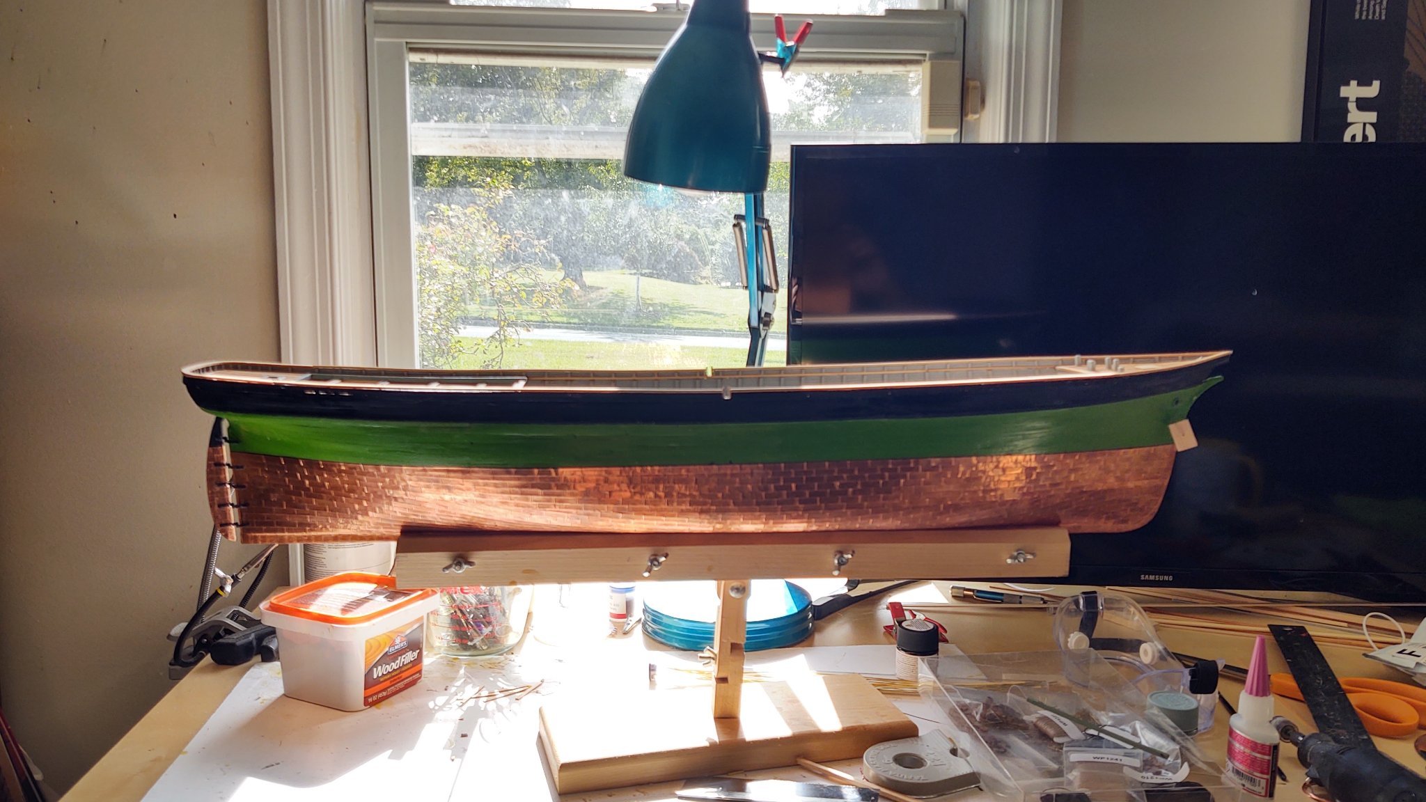
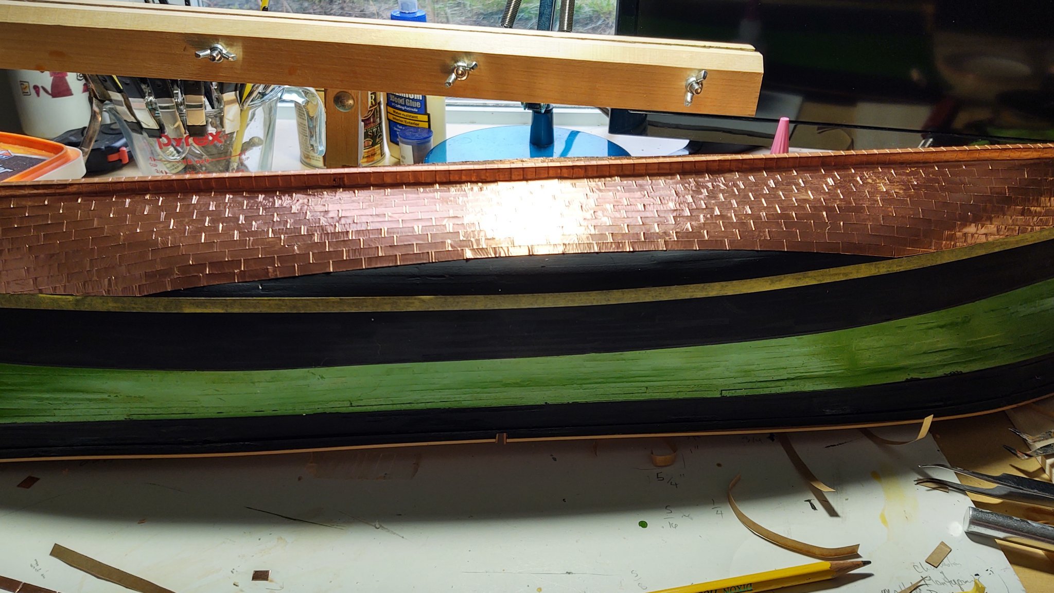
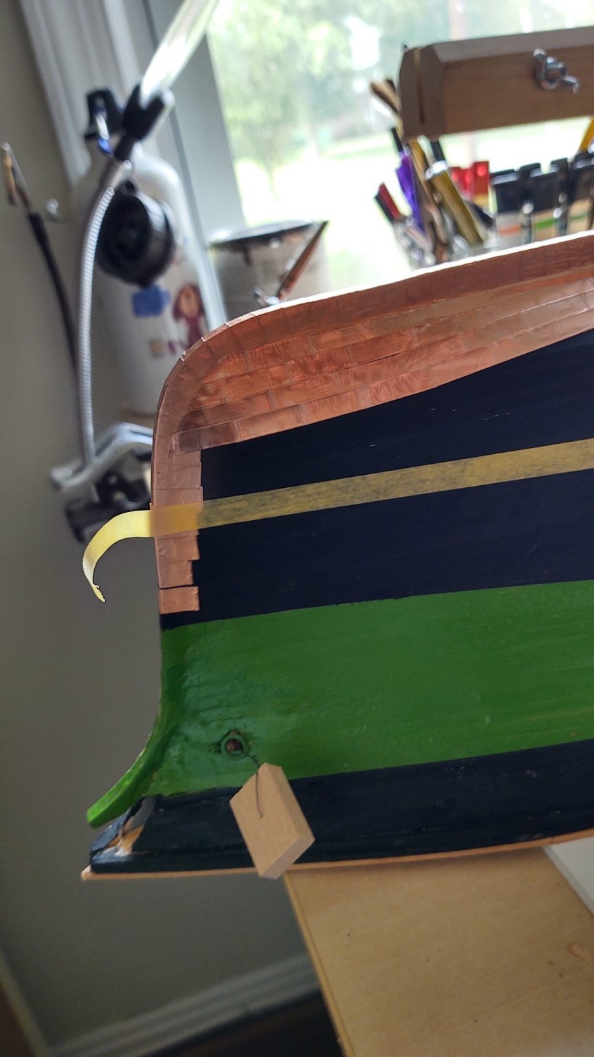
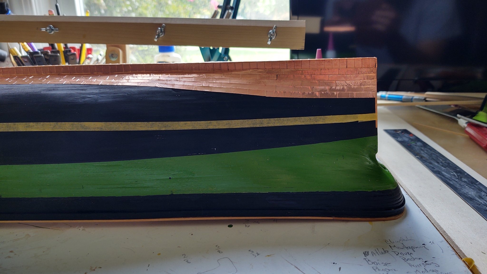
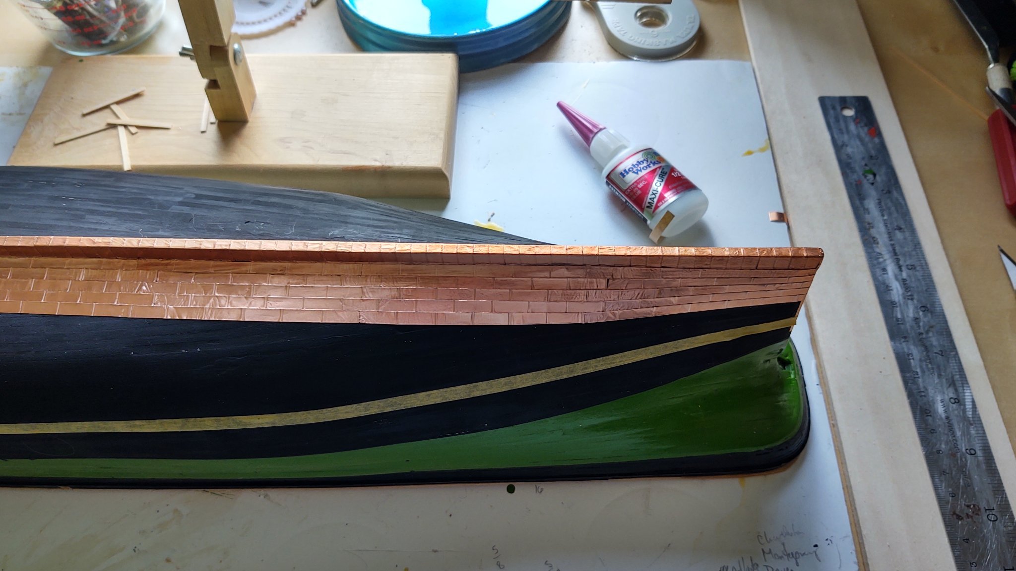
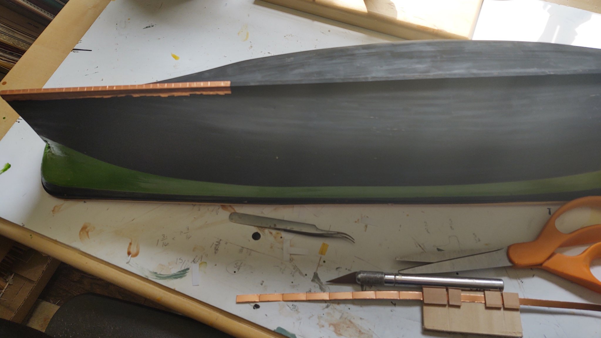
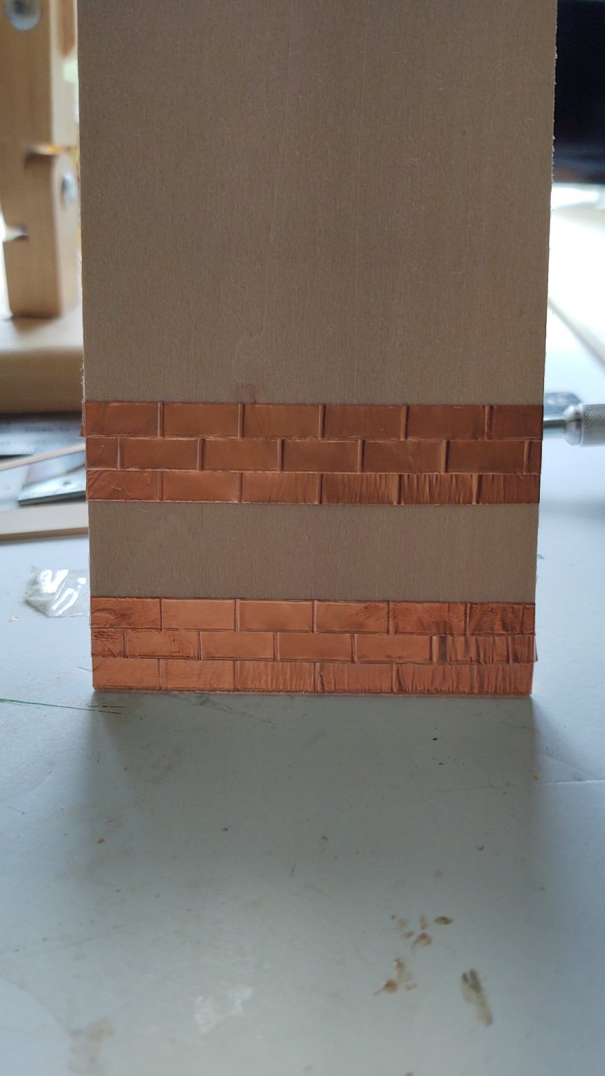
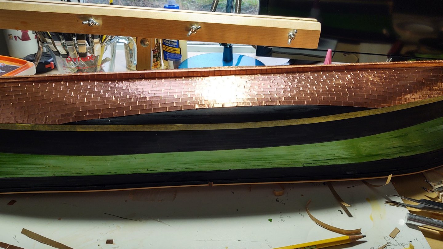
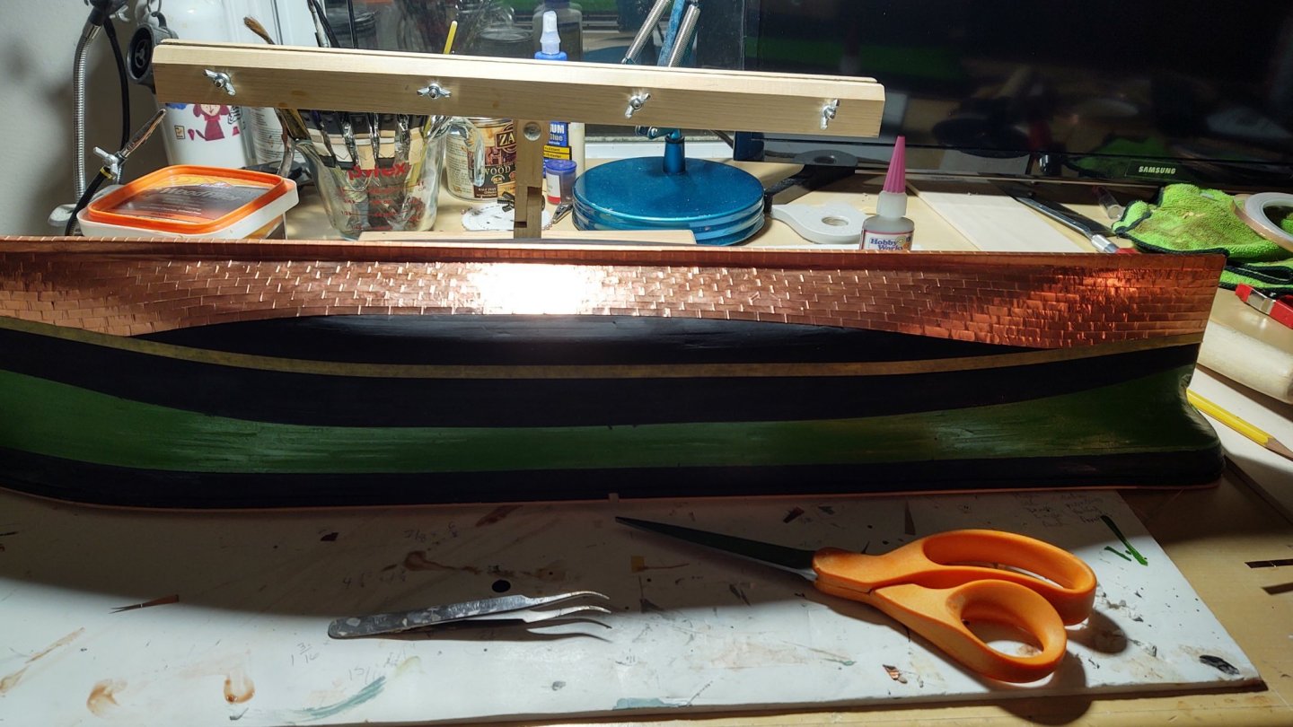
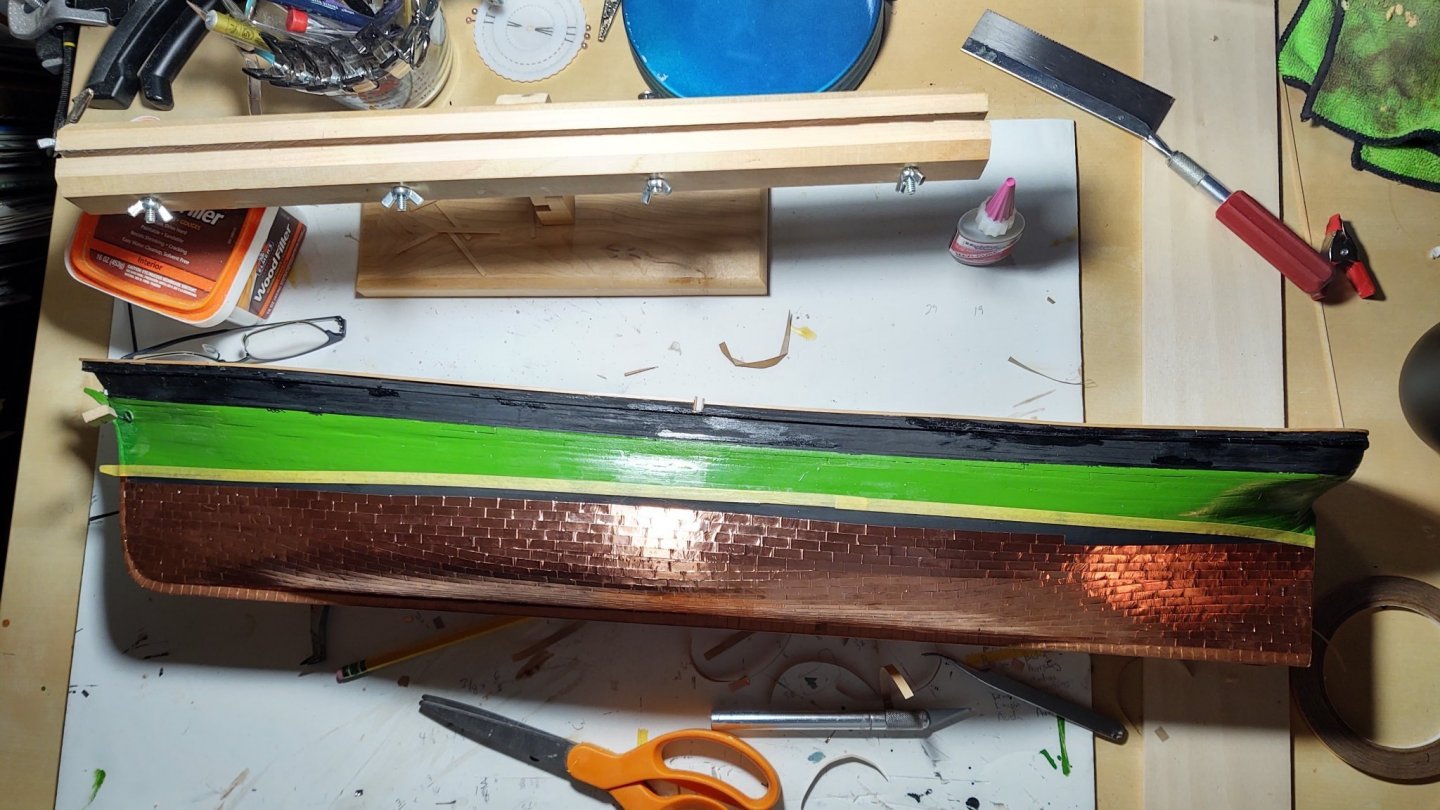
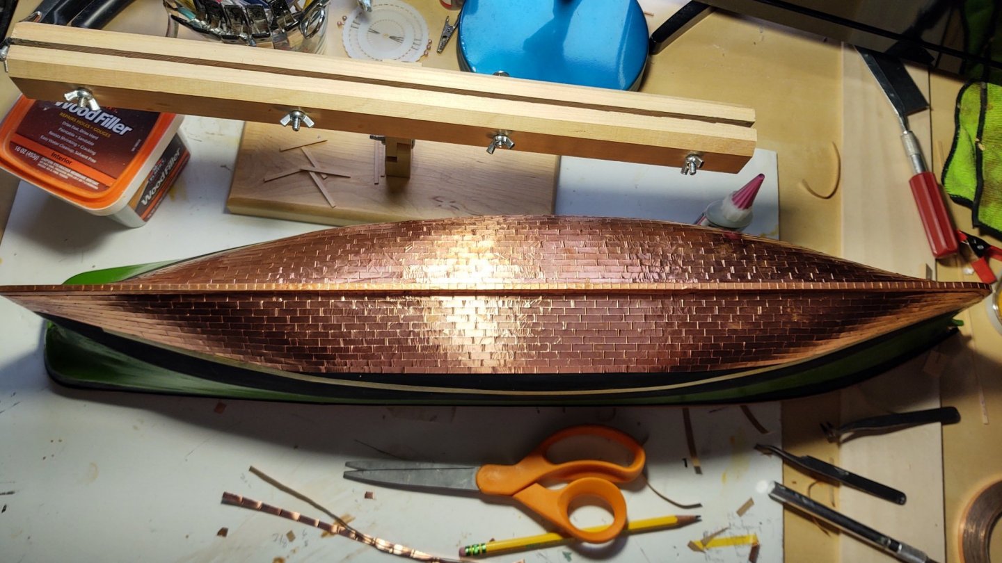
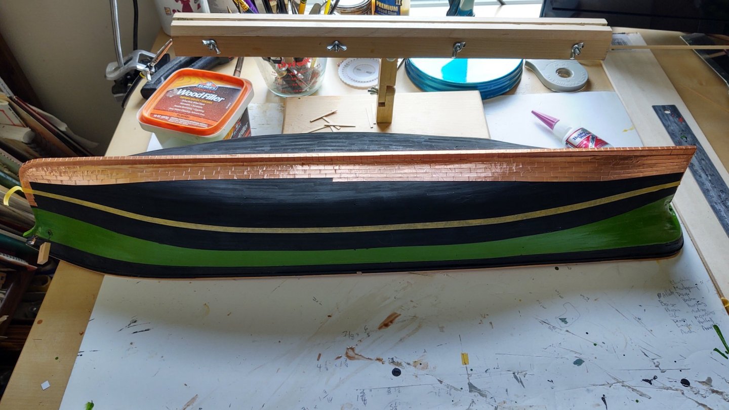
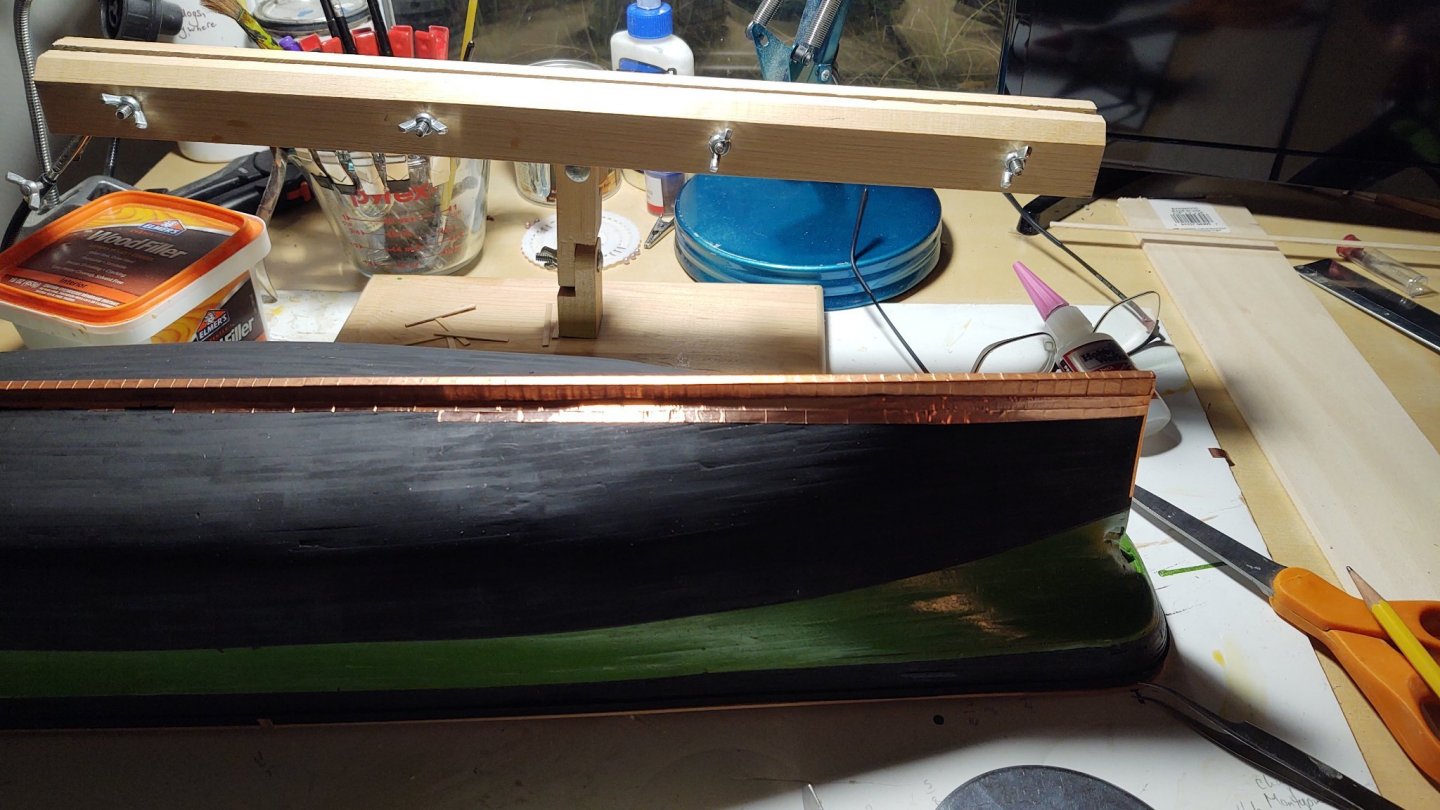
Coppering is complete. These first two photos show how I used the tape on the gore line to define the point where to stop the copper so that the next row above the gore line will sit neatly. And here is a view from above showing the starboard side mostly completed and the port side approaching the gore line. Once the second band of plates was begun, I put another line of tape on the ship with the tape centered over the load water line. It was there so I could copper up to the tape, have decent overlap, and still have a small amount of the black paint showing when I put the cap row into place. Finally, two views of the coppered hull, port and starboard. I used the kit supplied tape to cover the keel, figuring that the extra width wasn't a major issue, and used narrower (3/16"), black backed Venture tape that I got from a stained glass supply store for everything else as it was much closer to scale. The Venture tape is much better tape than the kit supplied tape. If I do another MSW kit, I'm throwing out the kit supplied tape as soon as I open it up. Next steps will be the rudder (so I can be done with copper), and the coamings that support the after deck house on the main deck (the only ones that I didn't install prior to planking). As always, thanks for looking in and the likes! Special thanks to Rob for his method which I adjusted to fit my needs. George K.
- 600 replies
-
- 8
-

-
-
- Flying Fish
- Model Shipways
- (and 2 more)
-
Good to get the right name. The term I used came off the Model Shipways plans for the Constitution
-
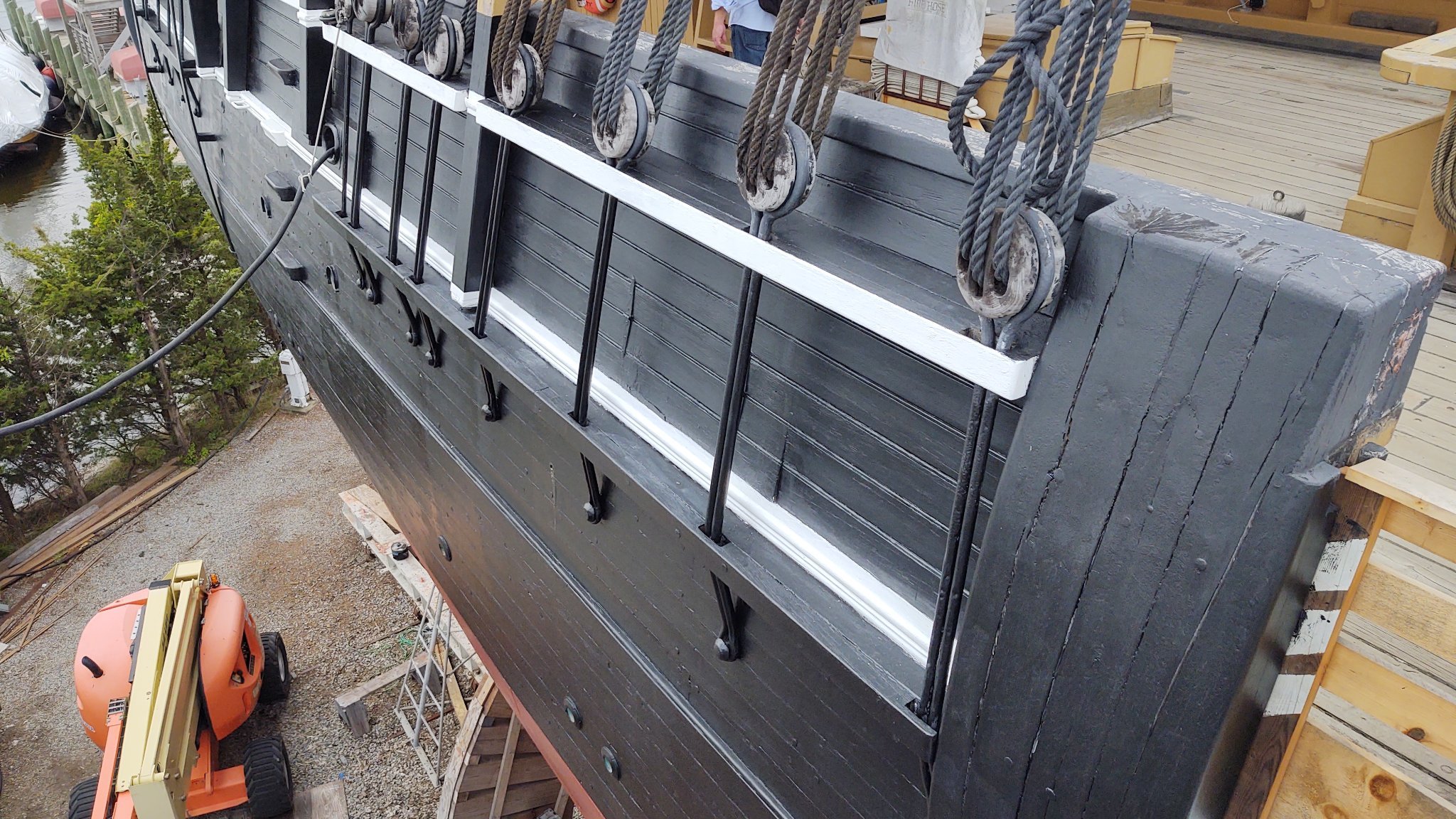
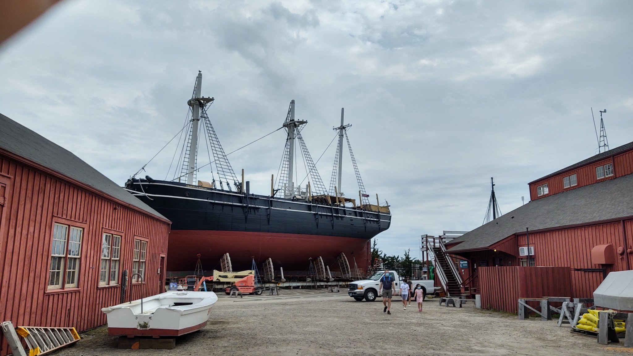
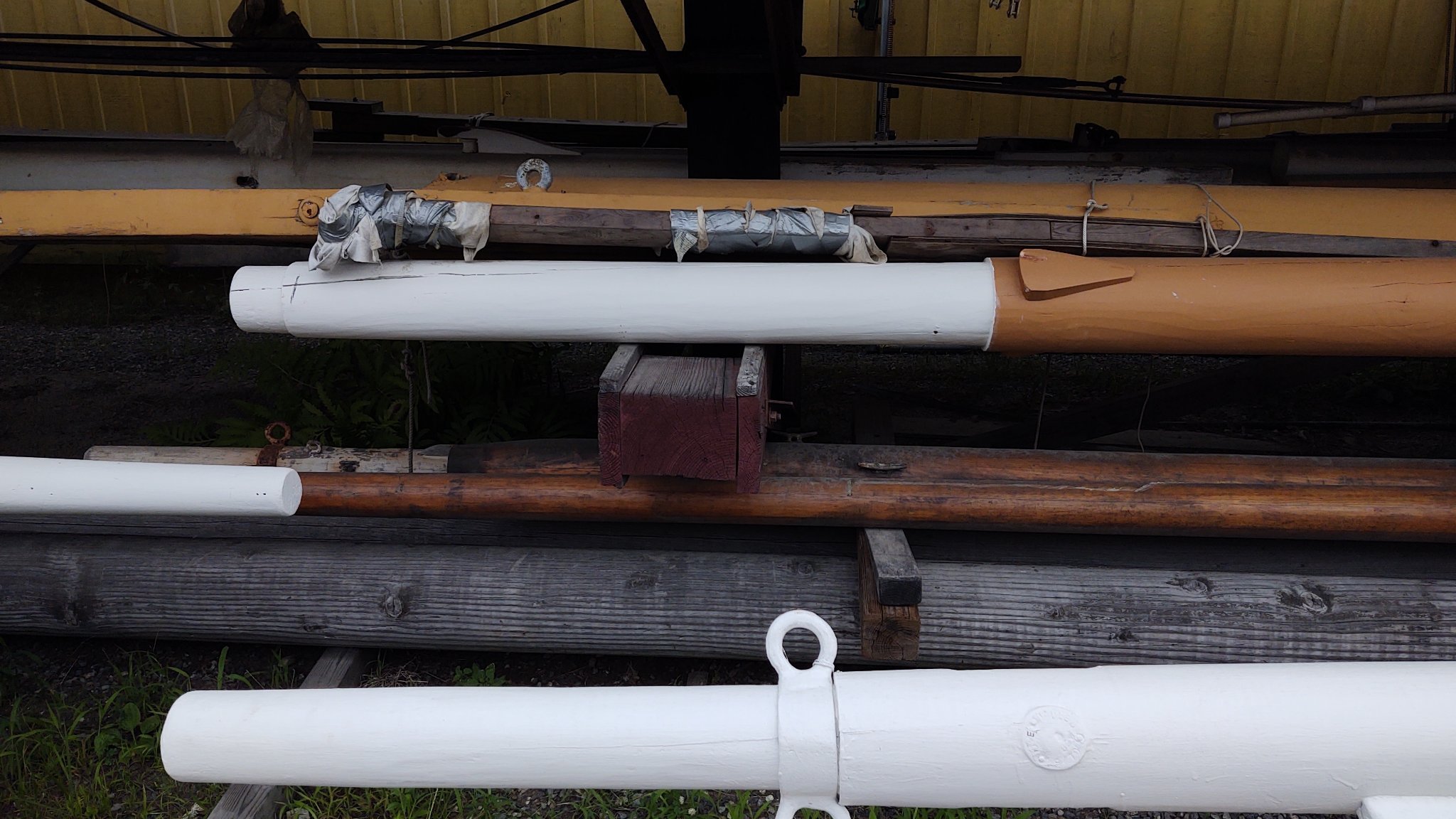
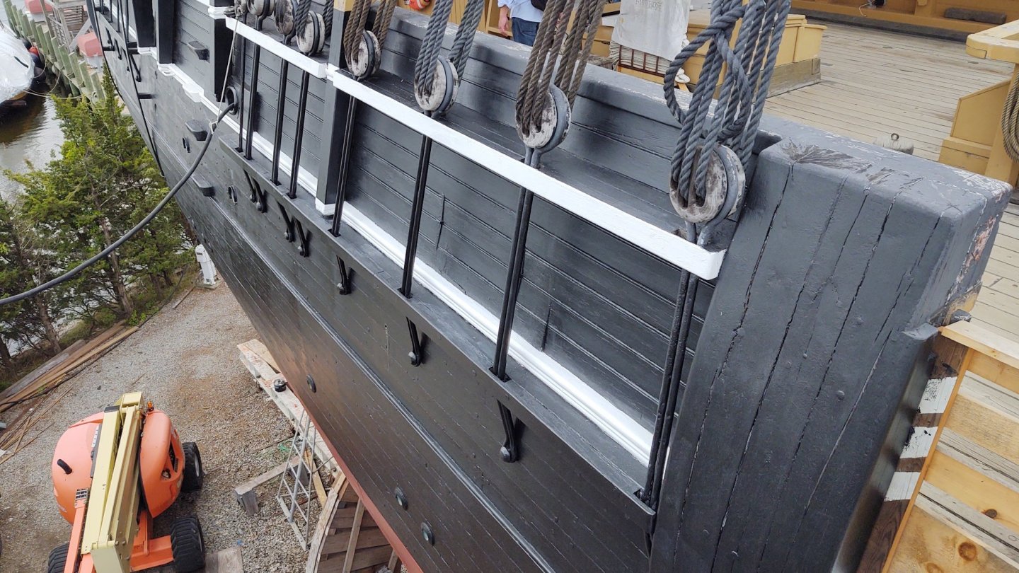
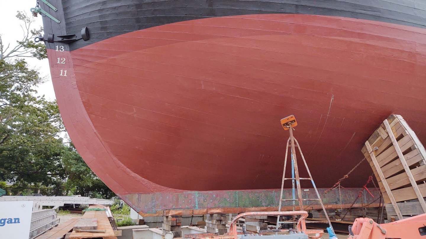
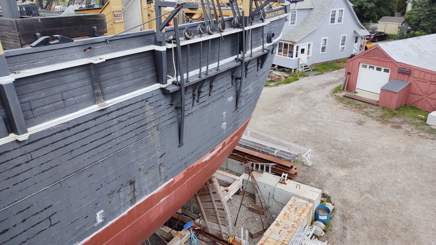
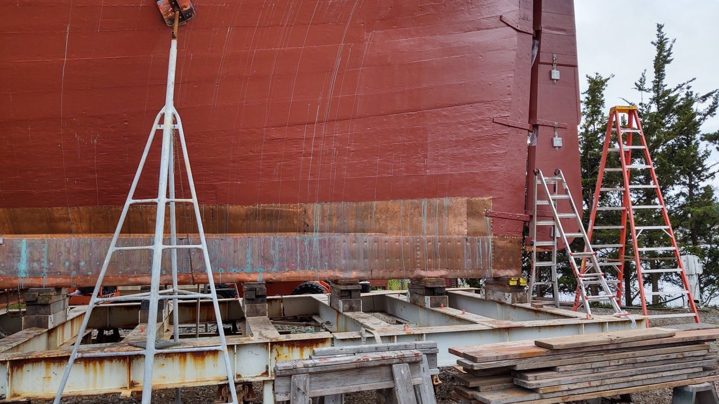
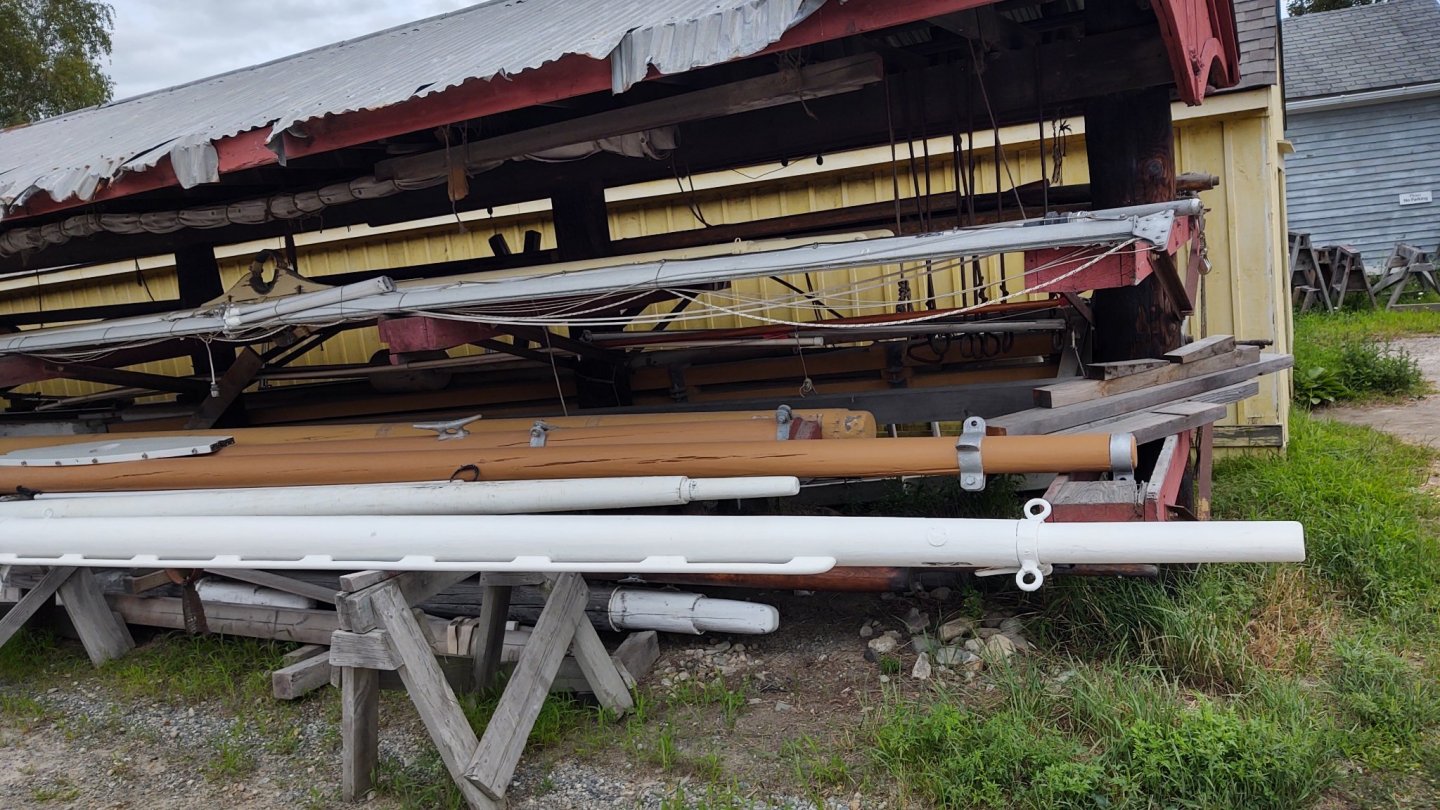
Well, a brief note. We were at Mystic Seaport and the Charles W. Morgan was out of the water on blocks getting some restoration work, including, it appears, its copper. Here are a couple of pictures of the ship on blocks and her copper. First, the whole ship. Her copper, fore and aft. I note that in contrast to the way it was described in the Fish instructions, the lower layers seem to overlay the upper belts. I also note that the copper is cut around the gudgeon, rather than being mounted on top of the copper. This makes sense, but I hadn't thought about it looking at models. Other observations. The foremast chain plates have backing links, the main and mizzenmast do not. The mizzen is smaller, so that makes sense, but why is the fore different? Extra strain from the jibs? The man at the museum didn't know. If you want to look at the Morgan's spars, now us the time. They are out for all to examine in forensic detail. And, I got a copy of this book! George K


- 600 replies
-
- 7
-
-
- Flying Fish
- Model Shipways
- (and 2 more)
-
The plans had the gore line marked, which I assume was Ben Lankford's (probably excellent) assessment of where to put it. Transferring it from the side views to the three dimensional object would be a pain, so I located the line on the stem and stern and laid the tape out so that it would flow naturally, thinking that such a flow was the whole point of the change of direction. It looks consistent with the plans, but since they are just guesses anyway, it seemed good enough for me.
-
What Rob said. I'm going to cut the ends of the plates at the gore line so that it will leave an uncoppered section that follows the tape, and then the Tamiya tape line will become the first line of plates in the next row with a changed direction
-
Hello! There are a few others working on this kit, although I think we are all mostly behind you at the moment. @Keithbrad80 has a log, as do I. Welcome to the forum!
-
Just a brief update, as we are about to go on vacation and then I need to return one of my children to college, so no updates for a couple of weeks. Coppering is proceeding apace, but even at 6 tiles per segment, I still have a way to go. The yellow Tamiya tape represents the first line of plates in the second belt (i.e. the bottom of the tape - or rather the top of the tape in these pictures) represents the gore line. Stay safe out there, and thanks for looking in and the well wishes. George K


- 600 replies
-
- 7
-
-
- Flying Fish
- Model Shipways
- (and 2 more)
-
Good to know. It seems to be working so far...
-
Wow. I would have expected the wheel to be inside somewhere (like the Monitor) rather than out in the open. I imagine that it would be an, ah, uncomfortable place during combat.
- 45 replies
-
- 6
-
-

-
- Tijger
- Paper Shipwright
- (and 2 more)
-
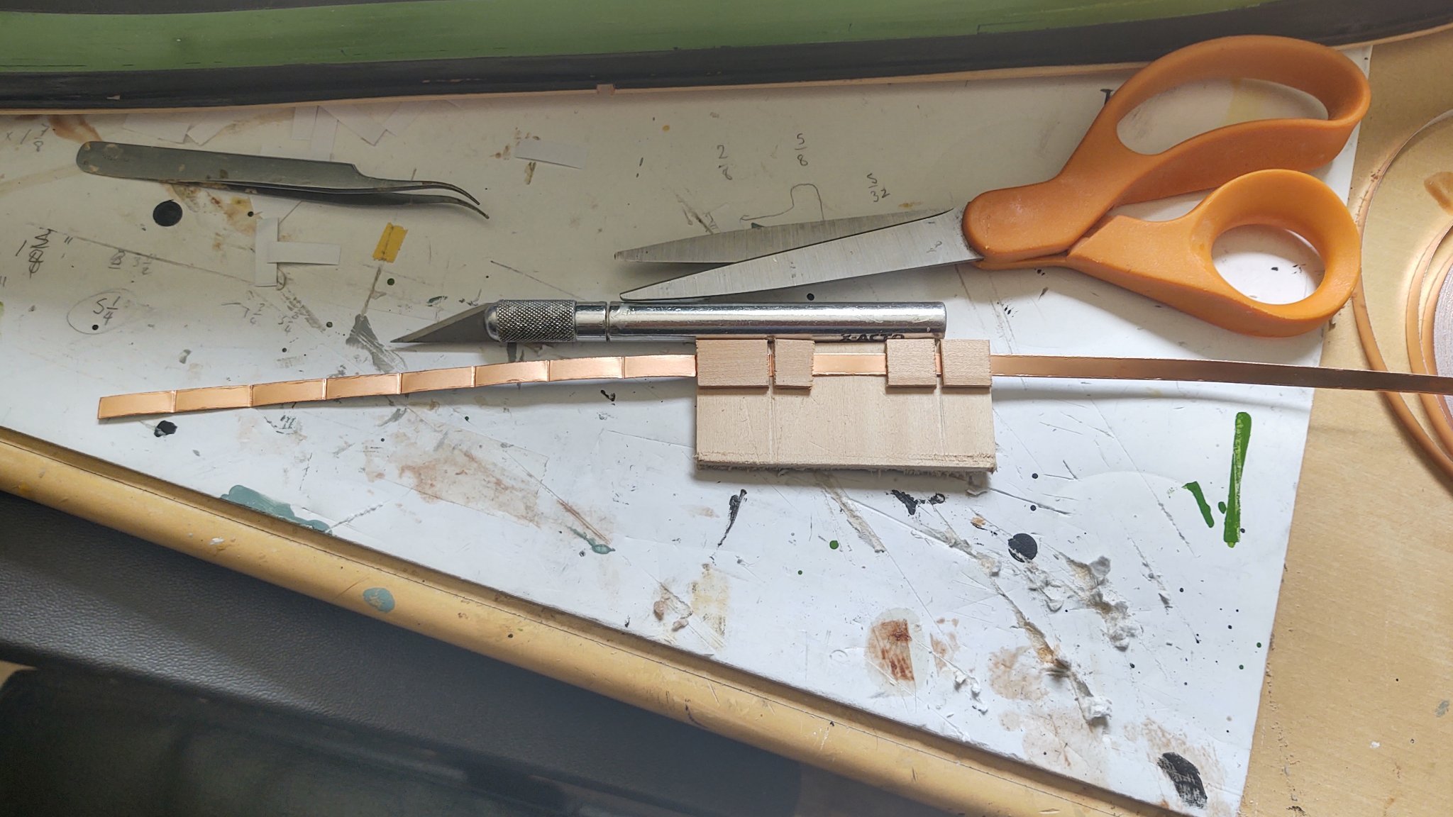
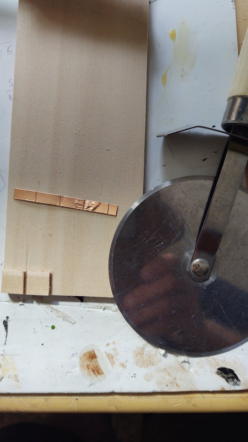
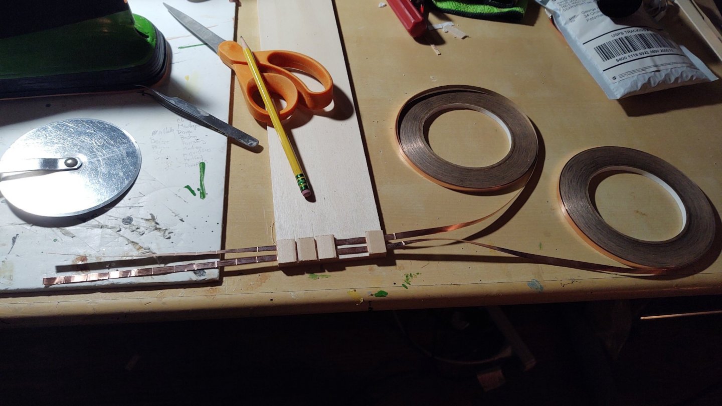
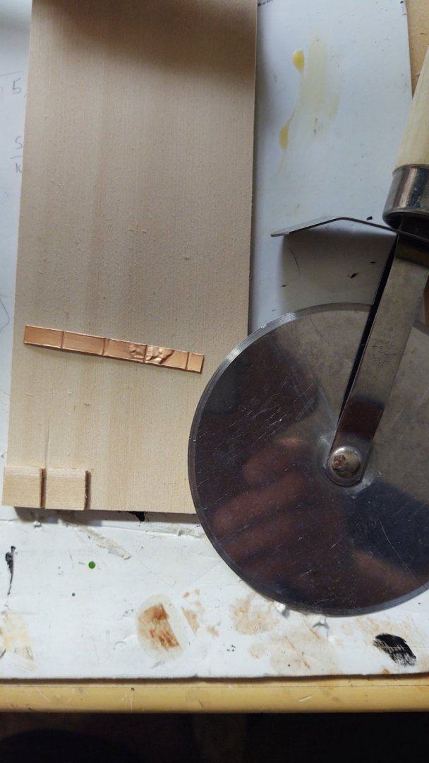
Very brief progress update. I decided to use the 1/4 inch copper tape to cover the keel. The picture below shows the jig I made to mark the plates for cutting. The individual plates are 9/32 long, are scored with a pizza cutter. The individual plates were cut out and applied in 1/4 inch segments to the keel as below. I allowed the plates to flow onto the hull since they would be covered up by the regular plates later. Once that was complete, I made another jig that feeds two 3/16 rolls of copper tape and has two guides for the pizza cutter so that I can make 4 plates at a time, pull it through, make two more plates, etc. as seen below. The 'plates' are 3/16 by 1/2, or at 1:96 they are 18 by 48 inches. That makes them a little taller than the 14 by 48 inch plates that are called for in the plans, but I question my ability to manipulate anything smaller. Finally I cut 6 plate segments and start laying out the regular plate segments, starting at the stern and aligning against the keel. The picture below shows two incomplete rows on the starboard side, but you get the basic idea. I am using the self-adhesive, rather than using Rob's method of gluing the paper backed tape. It seems to be working okay, although I definitely get more 'scrunching' than Rob's method produces. Once I get a little further, I'll mark the gore line with Tamiya tape so that I know where to stop. I expect that this is going to take a while, but it's more about perseverance at this point - kinda like making ratlines. As you can see, I've gone for the simple look, with the plate divisions marked by using the pizza cutter on the visible, rather than the paper backing side. This produces plate separators that are lowered rather than raised, and is a bit less obvious, but still definitely there. I am also going to suggest that the imperfections in the plate laying are giving it the surface interest that is usually formed as a result of the nailing. In any case, that is my story and I'm sticking with it. Thanks for looking in! George K


- 600 replies
-
- 6
-
-
- Flying Fish
- Model Shipways
- (and 2 more)
-
Looking great. None of the three MSW kits I've done or am working on provide many castings. I think the boundary condition for providing a casting is "can't be readily made with hand tools". That's fine with me, and it seems to be a distinction with some other manufacturers. George K
-
Did you make the capstan or is it a commercial product?
-
Looks great. I was wondering how to eventually replicate the pre cut planksheer that MS makes when I start Discovery, and I think that your method is the answer
-
Well, broke down and started working on the copper. Ultimately decided to go with the unadorned look given the scale. These are the tests with some 1/4 inch copper that isn't going onto the ship. The plates were made in my extremely high tech plate making apparatus, made from a bit of wood scrap and a pizza cutter. I used that to score the tape, which is then cut out into 6 plate sections. A sample section from a bit of damaged tape also shown. These plates at scale are 24" by 48", correct length, incorrect height. As you will see, the tape itself seems to have a bit of a raised edge, which I think can usefully serve as approximating a line of nails which would be about 0.4 mm wide at scale. I put together a couple of experiments below, the top rows were scored on the back, yielding a raised edge between the plates, and the bottom set were scored on the top of the plate. Both produce a pleasing effect, but I think that I will go with the variant with embossed from above as the plates seem more "separate" to me. I started from the bottom, and got better at applying the six plate segments as I progressed, so the top set is a lot cleaner looking (and the top row of the lower sections is better looking than the bottom two rows). The key is to hold the end of the strip down and peel off the paper backing without letting it curl up. Although I am going to use 3/16 tape on the ship, I may use some of the 1/4 to copper the keel, as it will fully cover it and allow cleaner overlaps than the 3/16 segments will (and it will allow me to get some value from the kit tape). As always, thanks for looking in. George K.

- 600 replies
-
- 5
-
-
- Flying Fish
- Model Shipways
- (and 2 more)
-
Thanks for the vote of confidence! It's been years since I've been out to Hyannis but next time I do, I'll have to stop by. In a similar vein, you may be aware of Chesapeake Mill in England (https://en.m.wikipedia.org/wiki/Chesapeake_Mill) that was partially constructed with timbers from HMS Chesapeake, formerly USS Chesapeake.
- 600 replies
-
- 1
-
-
- Flying Fish
- Model Shipways
- (and 2 more)
-
At the risk of getting philosophical, I tend to subscribe to the latter view. I personally lack the skill to weather effectively, and suspect I may not be alone. I also suspect that there is an axis of artist vs. engineer. I lean engineer and love the look of just commissioned/fitted out. But I'm still going to try to change the copper to new Muntz on my Flying Fish. Doing some experiments with different color paints to get the right shade. Regards, George K
- 3,515 replies
-
- 2
-
-
- clipper
- hull model
- (and 2 more)
-
Are you planning on putting in a gore line or just run it continuously?
-
The planking work is very nice. Are you planning to paint or go for a bare wood second planking with some kind of attractive veneer? It will look great either way, just curious. George K