


Bob Fraser
-
Posts
291 -
Joined
-
Last visited
Content Type
Profiles
Forums
Gallery
Events
Posts posted by Bob Fraser
-
-
Waaay back when I was much younger and in college one of our lecturers had a run in with a chuck breaking on a lathe - happened before I was there.
It hit him in the forehead but he was lucky, he was left with no brain injury and piece of skull removed that left a large visible dent.
Fast rotating objects and flapping clothes or other things really don't mix!
-
9 hours ago, Dr PR said:
Mini Iron II (Clover No. 9100) "quilting iron"
Thanks for the recommendation- - I've just added this to my Amazon list. Not just for me though, and hopefully get some Brownie points!😁
Admiral does needle felting, and uses hard beeswax on her models, particularly mushroom tops, to help flatten the fibres. After rubbing it on she then irons them. Also does this on the traditional jointed heirloom teddy bears felted noses to give them a slight shine.
-
4 hours ago, Yabuhebi said:
I saw Robert29's take on creating rings for the fire buckets. I put a toothpick in some scrap wood and pushed a brass barrel on top.
I was able to wrap thin PE sprue around the base and use CA glue to attach.
Scrap PE fret comes in handy. I've used it as hoops on barrels, smokestacks and capstan tops to simulate the iron metalwork.
I've also seen, for thinner strips and iron woolding bands, people use the soft lead tops off sprits bottles. Cuts bends and shapes easier than brass!
-
-
I have a Sculpfun S30 5W 40x40cm laser with air assist and limit switches. Cost is £280 or under $400 US.
I'm also using Lightburn, which has just doubled in price and will no longer update for Linux systems.
I'm using it at the moment to learn Lightburn and to design and cut the deckhouses and mast parts for the Mini Mamoli Cutty Sark that look the part even if not exact because of the very small scale.
The laser can cut a 0.5mm circle, however at small scales you do have to be careful with the width and length of the beam, and the direction of the cut, so an allowance distance between the cut lines needs to be factored in.
- mtaylor and NavyShooter
-
 2
2
-
Figures and paints also sold seperately, although early orders will get the paints for free at the moment.
Are the figures going to be resin or white metal? Will they be sold as a full set as all the figures shown, or different sets - such as the Nelson scene - seperately?
-
Hi LadyG
Do you have the model number 22170 or 22175?
22175 is the new version with the rowboat, and 22170 doesn't have one, so that may be the model you have.
Here's a link to AL Mary Jeanne (old) with photos, instructions and parts list downloadable as pdf files low down on the page. If it's 22175 there is also a link on that page for the model.
Hope this helps!
-
Good day Navyshooter.
I thought the name ship sounded familiar, I've seen this version of her over the years.
You were wondering about lighting -
the town of Blackpool UK has a version of her on display each year for their illuminations. It's a tram you can ride along the prom on.

🤣🤣
- mtaylor, Canute and NavyShooter
-
3
-
Nicely done Bob! I've been watching in the background but not able to comment - a good job well done. (lots of life things and 0 space to do anything until at least after christmas now keeping me otherwise engaged)
Glad the plans helped - I know I used them a lot. If you spot someone else who needs them please pass them forward 😁
All the best
-
Liking the light hull finish.
Can't find my printed instructions, but have found the 1-1 scale drawings. If you would llike them, pm your postal address and I'll mail them across for you.
I found they helped with some of the positioning of posts, ropes, eyes etc, but as each model has its own quirks I found you can't rely on them for exactness of heights.
- Keith Black and Knocklouder
-
1
-
 1
1
-
A nice tidy job.
You'll find the 1/96 a whole different beast that opens up a world of options 🤯 - just do a search and you'll find all the different options and methods that people are using from out of the box to huge kit bashes. As has been suggested, look at the one by Bruma, and the Ferreira build by rwiederrich, but don't limit to just those.
-
Following along! The original had walnut as the hull planking. Major differences are the PE parts and the "engine room" having the choice to motorise the paddle. And looks like no walnut at all!
They do have a set of figures available now too.
Edit -Found the original instructions and picture booklet for 20505.
I think the instructions were A4 size.
20505 Mississippi Instrucciones.pdf 20505 Mississippi color.pdf
- mtaylor, SiriusVoyager and Keith Black
-
3
-
Whilst built for the Confederate states, Alabama was built in the UK by Lairds of Birkenhead. Just a coupleof miles from where i used to live.
So she could have been built to British scantlings for the time period.
There used to be a model of her on display at the outdoor swimming baths at New Brighton that was built by a member of the CSS Alabama Association who wanted to raise her.
- mtaylor, allanyed, Frank Burroughs and 3 others
-
6
-
We have a Cricut Explore 3 - the machine is tied to the software for conectivity because of proprietary drivers, and the Cricut Design Space software is tied to the internet either via PC and USB, or the app version which connects via bluetooth to the machine. You can design in other art / graphics software and then import.
We also have another machine, the Sillhouette Curio. This is very similar to the Cricut in what it does with a couple of plusses. The Silhouette Studio software isn't tied to the internet, and the machine isn't tied to the software, there are several other softwares that can connect to it.
They can both do things the other can't. Both can use a range of non-oem pens and cutters with adaptors.
Cricut will import only SVG and DXF in it's free software, while Silhouette will import DXF, PNG, BMP, JPG, GIF, GSD and TIFF (SVG in a paid version). Both will do more filetypes in the paid versions. In both programs DXF will open with the lines of the design ready to be marked for operations, as will SVG, all other files will need to be traced with the software (needs clearly defined lines) but is relatively easy to do.
The Curio will cut up to 2mm wood, as will the Explore, but both need several passes and higher pressure settings to do so. Corners and curves are well cut.
We have both only because they were going being sold off cheap by people who no longer needed them, and they came with loads of materials and tools. My other half said "I need them for my makes, and you can use them too!"
Having only had these a matter of a few weeks I tried both for some small cutting and drawing I found the Curio the easier of the two to use, but I've a long learning curve.
If buying new neither machine comes with much in the way of tools, and Cricut oem are relatively expensive items.
If you're looking to buy one, check out your needs and match them to a model in the available ranges that can do what you want.
She also said a laser cutter / engraver would come in handy for her projects so now I've got that one to learn as well, with Lightburn being the software of choice - while building an enclosure and extraction duct for smoke and vapours.
-
Got to say, they don't give the best of instructions.
I have the Cutty Sark under way and had to use a lot of filler and shaping to get the lines looking anywhere near right.
(Stopped for now as life got in the way but will continue soon I hope.)
Use the photo of the ship on the box front to see what you may need to do.
Looks like a lot of filling and shaping to get the lines in the photo.
-
Dave asked earlier if the spreadsheet could be re-written to account for the foremast discrepancy.
I've managed to get the spreadsheet so it's unprotected, made it so you can see the rows/columns and sheet tabs. Also frozen some headers so they don't get lost.
The calculations can now be seen and followed, but they seem to go round in circles to me (probably just me not seeing it right).
Would an Excel wizz like to have a go?
Masting and Rigging - Danny Vadas - open.xlsm
Forgot to mention you'll likely get some warnings about active code. These will need to be allowed to run it properly.
- mtaylor, JpR62 and Kris Avonts
-
3
-
Hi Dave.
This is the DV spreadsheet on Windows view of the masting sizes for Diana as per the contract - available at the nmm here Artois Contract
Using Extreme Breadth as 39' and length of lower deck as 146'
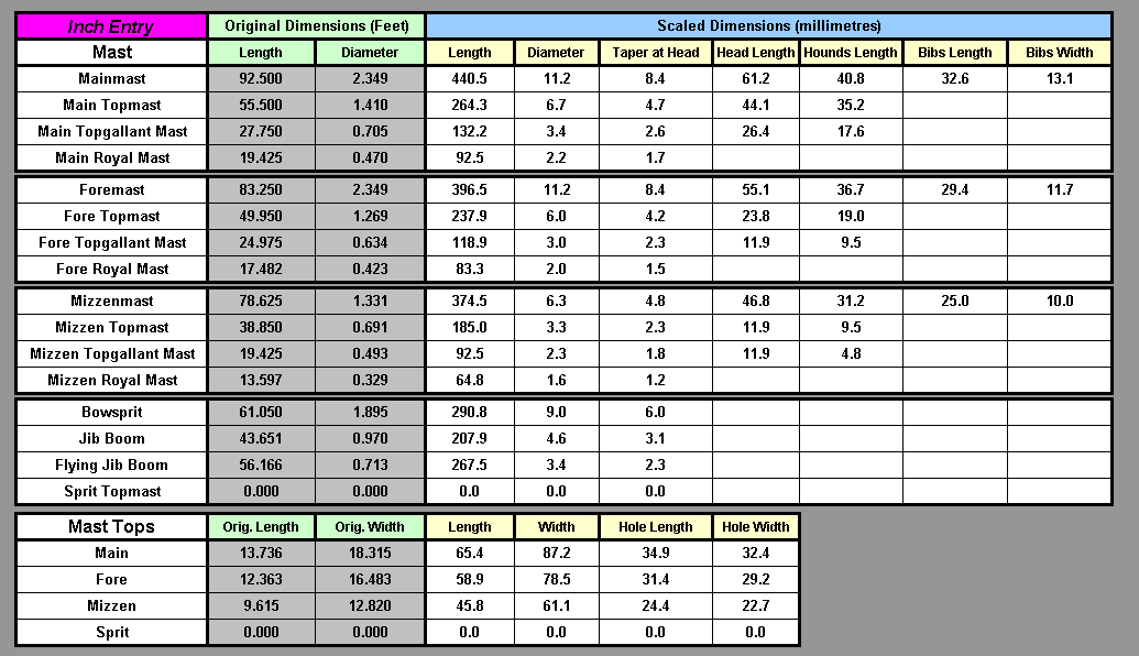
Steel gives the same main mast length as the spreadsheet, 1745 Establishment as 88.92'
There were amendments to the 1745 Establishment for larger ships in the intervening times.
Using Lees the 1/64 diameter comes to 10.80mm
Does the same for my little sloop, too!
You'd need to do the math for the other given sizes of the fore to work out if there are any other differences.
The spreadsheet is protected from editing, and I'm not a genius with spreadsheets.
-
Hi Allan, Dave.
Allan - I'd seen that comment about the dates before, but couldn't remember it fully. Thanks for the reminder.
As you say, a fantastic resource.
I'm no expert or have extensive experience in these calculations, and my use has only been with this one ship.
The ship I based my comment on was a RN sloop built 1756/57 and would most likely have been built to the 1745 Establishment, quick mast drawing measurements taken with a brass caliper.
I would imagine that you are aware of all the different calculations over the 18th Century 🤣 I wasn't at all except for the 1745 Establishment, and was surprised by the variations 🤯
I was hospitalised last year for 10 days with covid and while I was there I did a little research on the sloop to give some working mast dimensions. but only from 1711 to 1794, and came up with the following table of authors.
Purely for my own benefit!
--------------------------
Dimensions for Bonetta 1756 as designed -
Deck 85’10”, Breadth 24’ 4”, Depth in Hold 10’ 10”, Keel 78’ (as per Ollivier)1, 220 40/94 tons (profile plan ZAZ4368 RMG)
Dimensions for Bonetta as built -
Deck 86ft 4in, Breadth 24’ 6”, Depth in Hold 10’ 10”, calculated Keel 78’5”, 22760/94 tons (Winfield, 2007)
RD is Range of Lower Gun Deck or upper deck on a single deck, EB is Extreme Breadth, DIH is Depth in Hold, K is Keel length, BMF is Beam Multiplication Factor.
Calculation Information
Main Mast Length (Ft In)
Beam Multiplication Factor
Date
Name
Formula
As Designed
As Built
As Designed
As Built
Reference
Davis
EB*BMF
2.66
-------------
(Marquardt, 1986)
1711
Establishment
(RD + EB) / 2
(Lees, 1979)
1719
Establishment
No Change to 1711
-------------
-------------
-------------
-------------
(Lees, 1979)
1723
Anderson
EB*BMF
2.25
-------------
(Marquardt, 1986)
1726
William Sutherland**
(((EB + DIH) * 3) / 5)*3
(Marquardt, 1986), (Sutherland, 1726)
1735
James Love
((K + EB) * 2) / 3
(Marquardt, 1986), (Love, 1705)
1737
Blaise Ollivier
EB*BMF
2.33
-------------
(Ollivier, 1737)
1745
Establishment
EB*BMF
55.479
55'7 3/4"
2.28
-------------
(Lees, 1979)
1752
Duhamel Monceau 1
EB*BMF
2.5
-------------
(Marquardt, 1986), (Monceau, 1752)
1752
Duhamel Monceau 2
(EB*2) + DIH
(Marquardt, 1986), (Monceau, 1752)
1756
William Mountaine
(K + EB) / 2
(Marquardt, 1986),(Mountaine, 1767)
1768
Chapman
EB*BMF
2.43
------------
(Marquardt, 1986)
1794
Steel
(RD + EB) / 2
55.083
55'1"
-------------
(Steel, 1794)
** EB+DIH in feet, multiply by 2 and then divide by 5 = length in yards. Multiply by 3 = feet and part.
------------------------
Hoping my calculations above are right, Dannys spreadsheet first entry for a sloop is 1794, and his calculations came out as 55' 7" to 3 decimal places, 55' 6" to 2 decimals for the inches part as input.
Looks like the 1745 Establishment is used up to at least that date in the spreadsheet, as per Lees. Steels dimensions come out smaller.
I have the Lees and Marquardt books, Love, Monceau, Mountaine, Sutherland are available as Google books.
Dave - I think even an XP based laptop with Excel on it will run the spreadsheet.
BTW, a distant cousin of mine captained Diana in 1799!
-
4 hours ago, DaveBaxt said:
but I was unable to use the buttons on the front of the sheet
Hi Dave.
This is because Dannys sheet uses active-x controls to do some of the calculations. Google sheets doesn't alow the use of active-x.
I don't think it will run on a Chromebook, Office 365 on line also doesn't use active-x controls.
You'll need you use Excel on a PC to open the spreadsheet to get it to work as it should.
I just ran a quick check (Dannys) and measured the results against an NMM print I have which came out exact to the drawing.
-
Billings boats direct - Cutty Sark topright of the blurb are links to instructions and riging manual
-
12 hours ago, Cleat said:
I found it difficult to work the rigging while the mast and gangway moved around. Parts of the routing didn’t make sense; I wasn’t sure where some lines ended.
ALs rigging diagram is a bit confusing, took a while using the big picture and the photo manual.
12 hours ago, Cleat said:adjusted the lines to get the gangway to the proper height but between sorting out the spaghetti of lines and taking up slack it had moved.
I opted to be awkward and installed 2 of the things! 1 up and 1 lowered, the height can be a personal choice. whatever looks good to you.
-
Coming together nicely. Neat job on the mast block!
-
Iron on transfer paper might work - use it with an ordinary inkjet. I've used this on t-shirts but not on silkspan.
Sublimation printing works the same way but needs special inks in a dedicated printer on sublimation paper, can work with an iron, but usually a heat press.
-
52 minutes ago, Cathead said:
Or you can use a tiny dab of glue on the end of the line, which you can then shave into a sharp point with a knife.
That's what I used, except I made the glue 1/2 inch to 1 inch long to act as a needle to hold, rather than holding a flexible line when threading the block.
Much easier when you've got fat fingers like me! 🤣
The needle threader doubled the line thickness and I couldn't pull it through most of the supplied blocks as the holes were too small. Even with the glue method some holes had to be widened with a micro drill just a little.
Planking Tutorials PDFs
in Planking Downloads and Tutorials and Videos
Posted
You could try from the NRG resources page at the top of thsite header NRG Articles
This works in both Chrome and Browser for me.
Just in case, plankingfan.pdfLining Off your hull for planking.pdfhere's the article refered to, with the seperate planking fan.