
HOLIDAY DONATION DRIVE - SUPPORT MSW - DO YOUR PART TO KEEP THIS GREAT FORUM GOING! (Only 20 donations so far - C'mon guys!)
×


mbp521
-
Posts
1,002 -
Joined
-
Last visited
Content Type
Profiles
Forums
Gallery
Events
Everything posted by mbp521
-
 Keith, Its not the Tennessee, but I thought it was pretty ironic. I was perusing through Facebook when I ran across this post from the NRG showing the hoisting of the stuns’l on the Pride of Baltimore II. While it’s not identical, it kind of shows something similar to your drawing above. https://m.facebook.com/prideII/videos/897213800806335/?refsrc=https%3A%2F%2Fm.facebook.com%2F127406460658253%2Fposts%2F3889303477801847&_rdr -Brian
 -
Simply beautiful Johann. -Brian
-
Vlad, glad to see another build from you. Looking forward to following along on another beautiful ship. -Brian
-
Dan, I was going back through my build log looking for something I had previously posted when I ran across this post. I know that it has been a while since you posted it, but I believe the info that you are referencing about the modifications to the armor plating was noted in the "Hardluck Ironclad: The Sinking and Salvage of the Cairo" by Edwin C. Bearss. I read this book a couple of months ago and I remembered that he writes about the testing of the plating at the Cairo, IL shipyard where the test fired cannon balls into the plating from across the river. Bearss also discusses where Lieutenant Bryant of the Cairo had the addition of another course of Oak planks and plating on the forward three surfaces of the pilot house for extra protection after Flag Officer Foote was injured when the Louisville and St. Louis pilothouses were damaged during battle at Fort Donelson. This is the reason for its odd shape. Originally designed as octagonal, the additional forward plating change its look. It was also at this time where the viewport flaps were added to the protect the pilots from sniper fire. As for the railroad iron being added to the forward casemates, this came about from the Cincinnati being rammed by the Confederate gunboat General Bragg by her starboard paddlewheel during action off Plumb Point. The General Braggs paddlewheel had sideswiped the Cincinnati and climbed the casemate ripping timbers above and below the waterline near her bow. This prompted the Federals to make serious adjustments to protect the boats during frontal assaults. Scrap and captured railroad irons were fashioned to the casemates just forward of the front port and starboard guns for this added protection. Bearss does not say whether all of the City Class boats received this upgrade, but does state that the Cincinnati received it during her repairs after she was raised, and the Cairo definitely had them since they were attached during her salvage. I am still not able to find any documentation on whether or not the aft casemate was armored. The designs called for it but there are no resources that say that it was installed. None of the pictures of any of the boats show this and there is no evidence of the Cairo having it either since this section of the boat was lost during the recovery efforts. So without having any info on it, I m not going to armor plated the aft casemate. -Brian
-
...and away we go! Great start. By the way, not sure if you previously mentioned it or not, but what is the color you are using for the coamings and waterways? I like it! -Brian
-
Eric, Beautiful job on the base. The chatter marks from the sawmill add a nice rustic touch to the whole ensemble. All of the boards on the ship would have been hand hewn so there would be plenty of them on the hull to fall right in line with the base. I think you are selling yourself short and don’t see why you don’t use that base for the permanent display. As for the workspace, I feel your pain. I’ve been dealing with the same issue for over a year now. Since the pandemic, we have been working from home and my shipyard has had to share room with my home office. I have stuff stashed in every corner of the room and since my build is so big, it takes up the majority of my work table. Not a lot of wiggle room. I sometimes have to resort to TV trays as extra work space. Also with the way lumber prices are right now, it may be some time before I get to build my permanent shipyard out in the barn. I guess we make do with what we have and soldier on. -Brian
-
Keith, It’s always worth it when the tedium pays off. Even more fun getting to do the happy dance. Beautiful job on the jack stays. -Brian
-
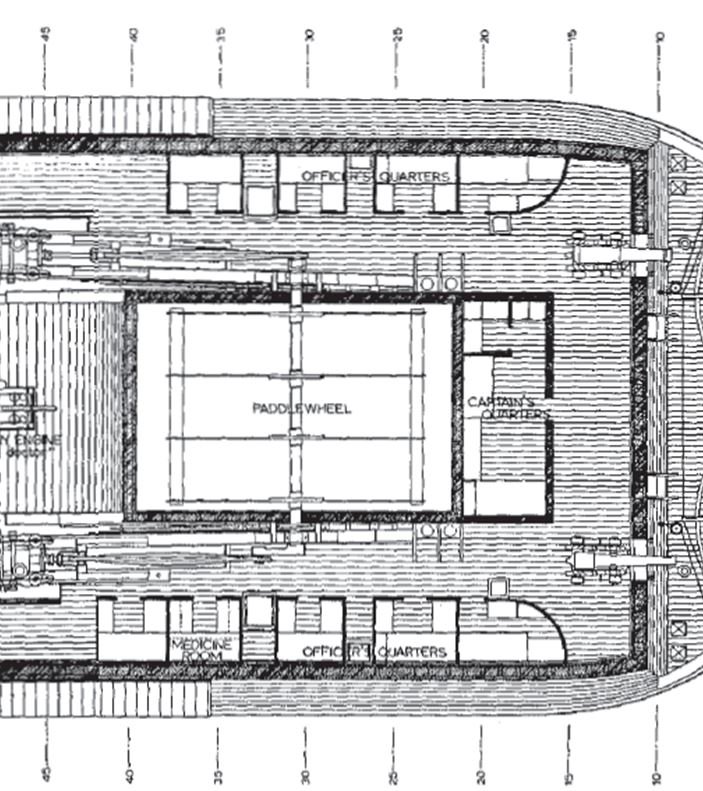
Brett, Thanks for stopping by. Good to see another fellow Texan on here. HSR stands for the Historic Structure Report. This is a document that the National Park Service made available on their website. It contains detailed information on the salvage and reconstruction of the Cairo, her permanent berth structure, and numerous detailed drawings of what she looked like after she was rebuilt. These drawings are what I am mostly basing this build off of. If you wan to take a look at them, the PDF can be downloaded from the NPS website: https://www.nps.gov/archeology/sites/subcul1.htm just scroll down to Mississippi and select the USS Cairo Historic Structure Report. -Brian
-
George, you’re a braver man than me. I always put the planking down then come back with the coamings because I don’t think I could ever get the planks to line up correctly if I didn’t. I’d have gaps all over the place. However it is a better method if you are painting them. It gives a cleaner look without the worry of getting (and cleaning) paint from the deck. Can’t wait to see what they look like installed. -Brian
- 602 replies
-
- 1
-

-
- Flying Fish
- Model Shipways
- (and 2 more)
-
Eric/Ken, I guess it was a poor choice of words. Just to me all the “fiddly bits” of this build don’t substantiate to much until they are actually placed on the boat. But I guess if I look back on it I was a little productive since my last update. I have a whole shelf with the cannon carriages, ammo crates, cannon implements and various other odds-n-ends just waiting to be installed, just getting a bit anxious to see them in place I suppose. -Brian
-
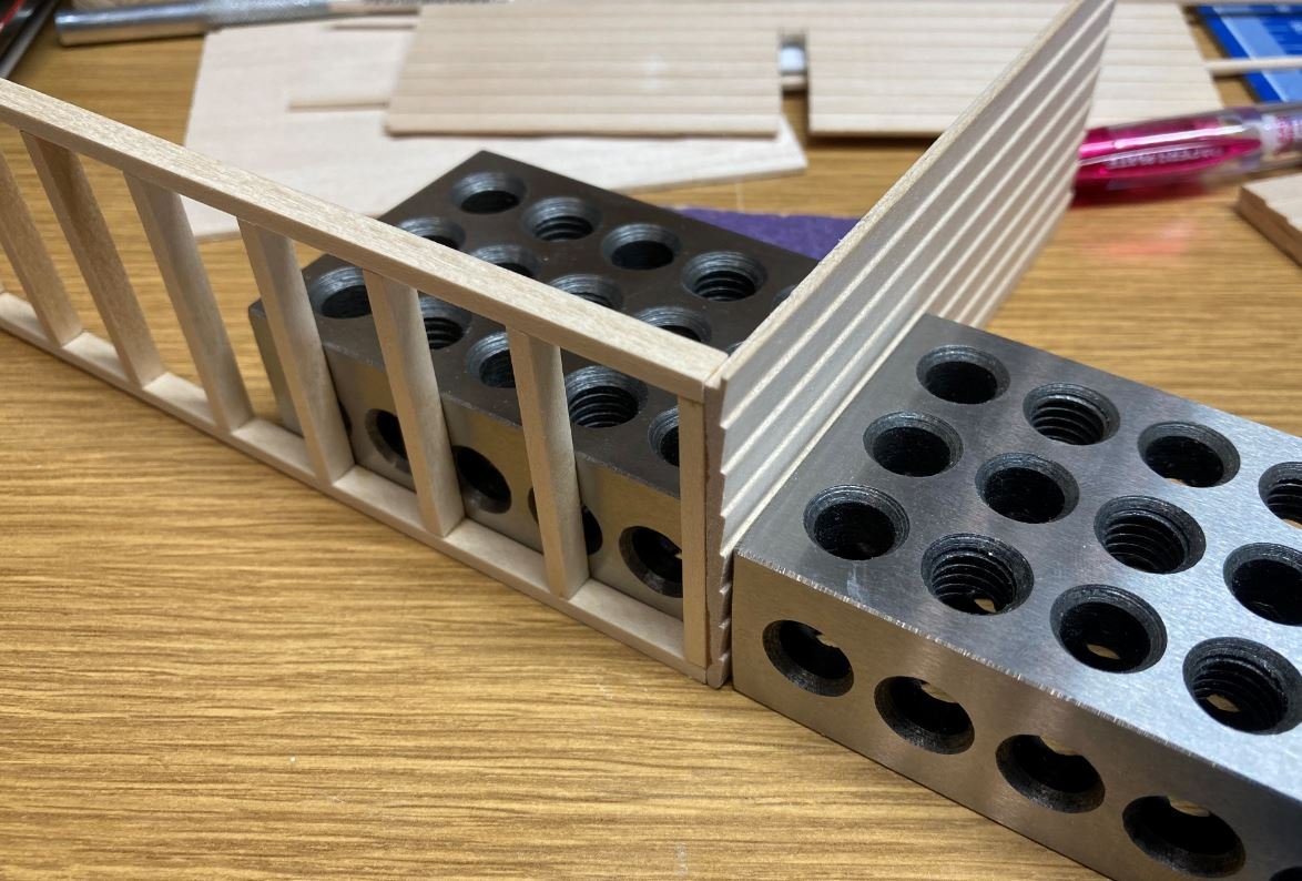
Thank you Gary. I guess that is one of the fun challenges of scratch builds, finding a way to get yourself out of that corner. As for the 1-2-3 blocks, I picked these up a couple of months ago and I can’t figure out how I ever got along without them. They are indeed handy tools to have around. -Brian
-
Thank you Keith. All the little bits add up after a while. It’s going to be nice when they are all in place and not scattered about my work bench. -Brian
-
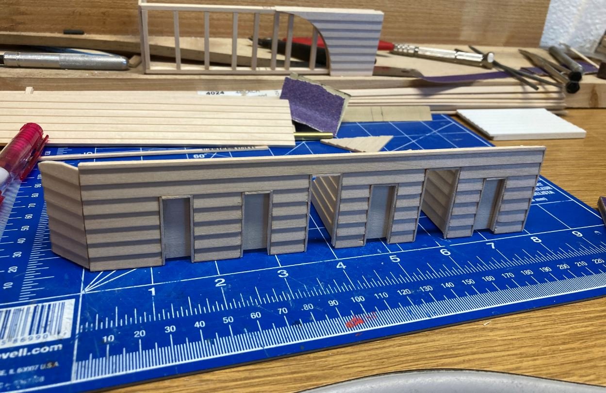
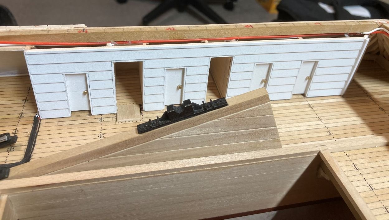
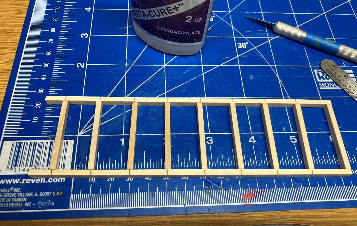
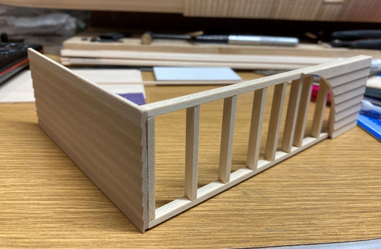
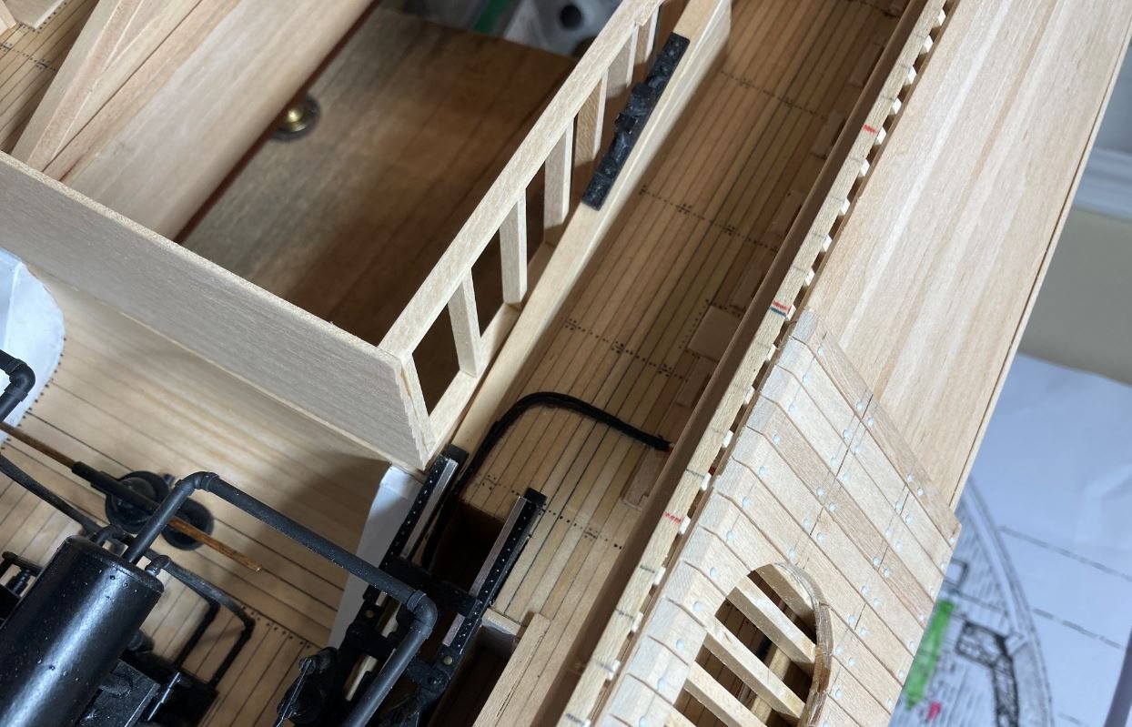
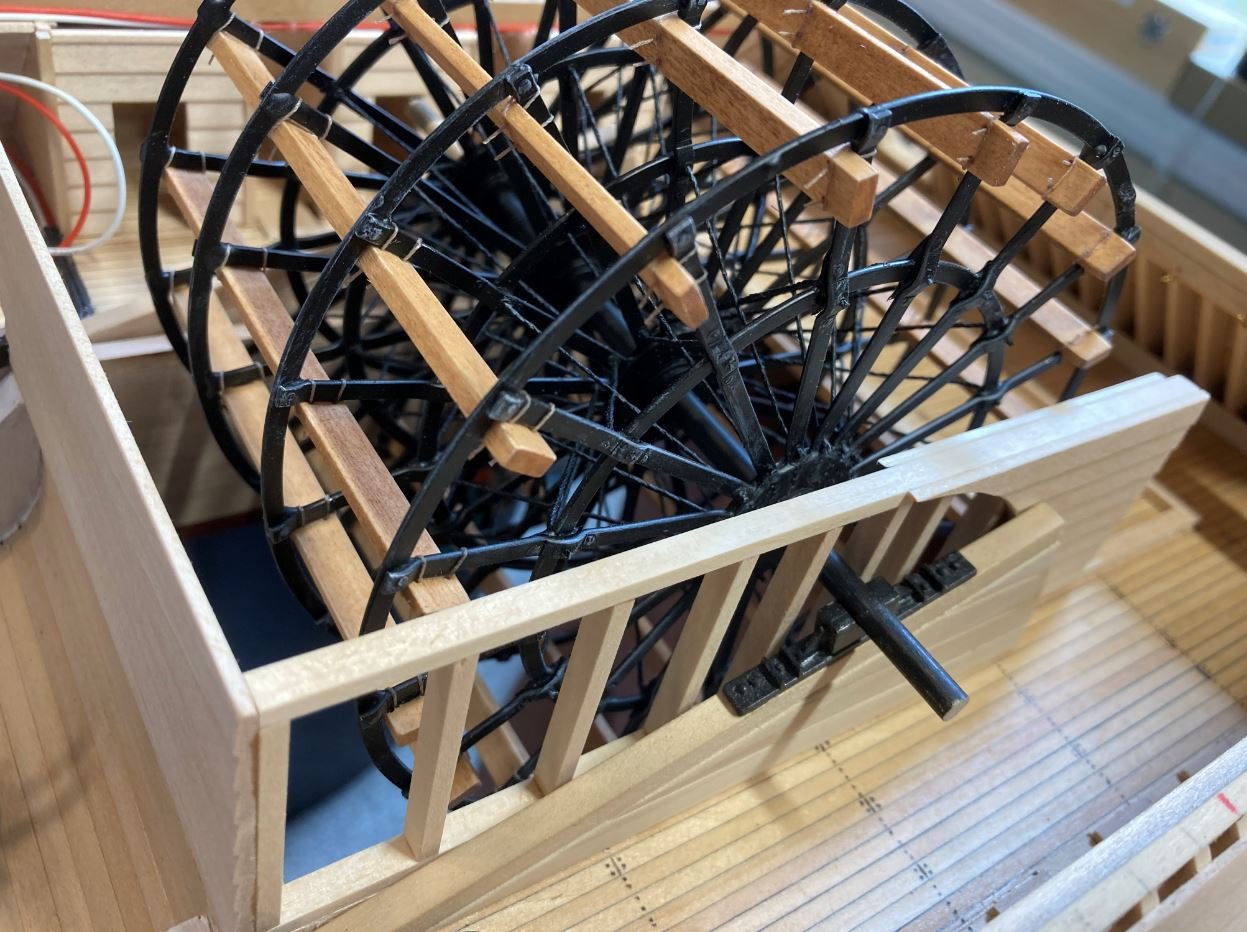
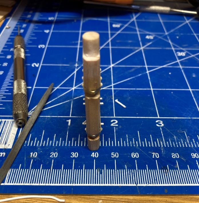
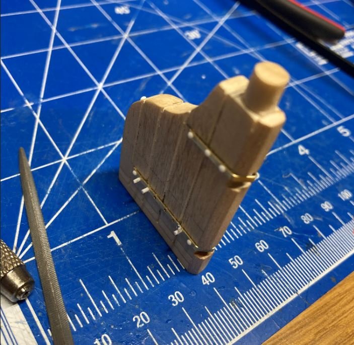
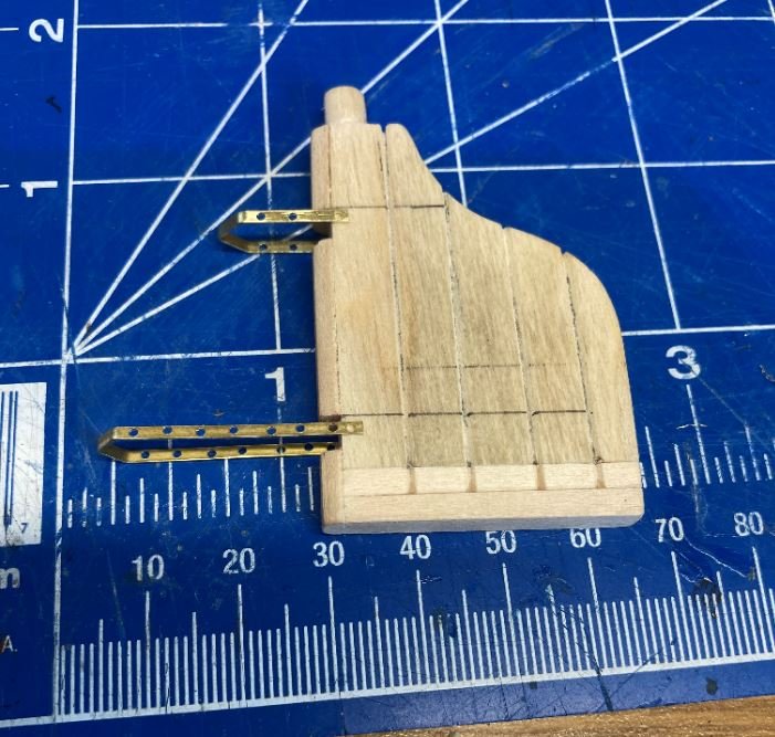
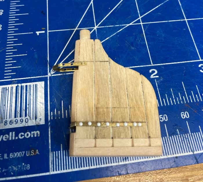
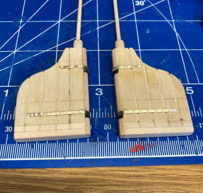
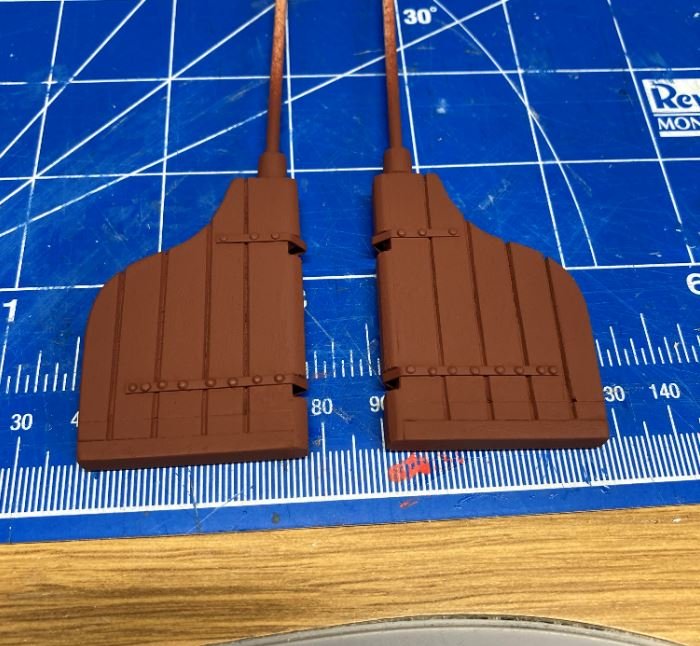
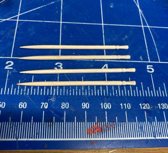
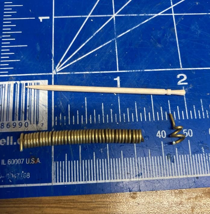
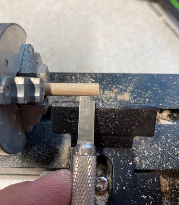
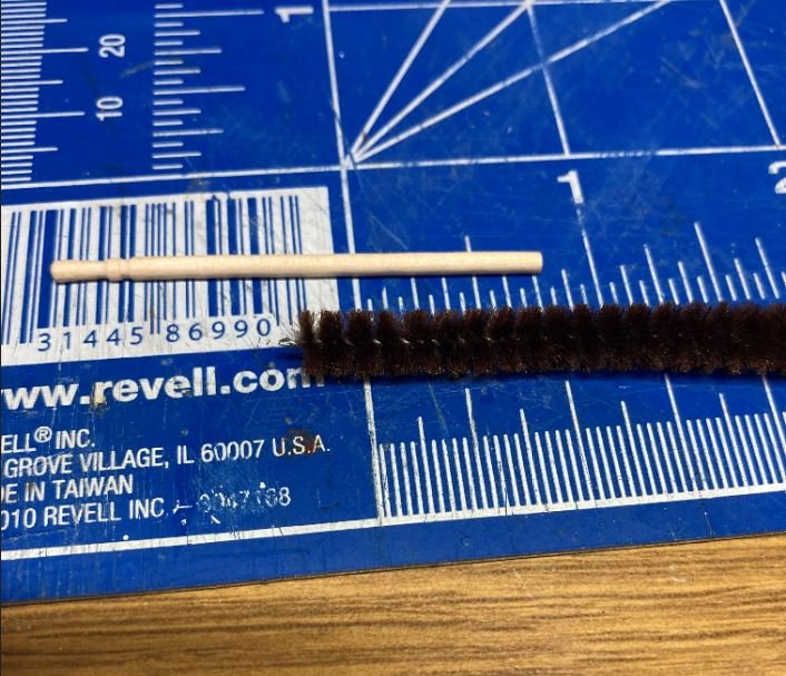
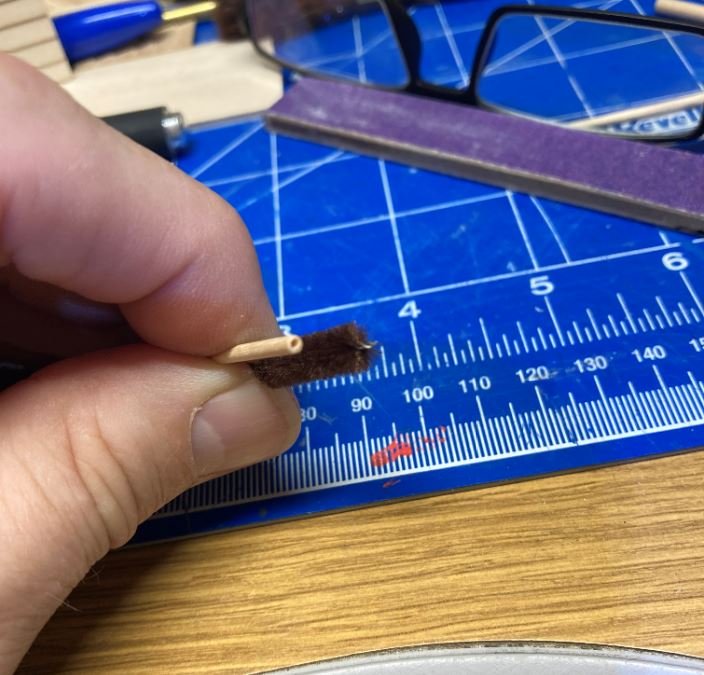
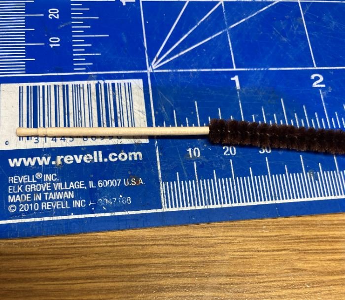
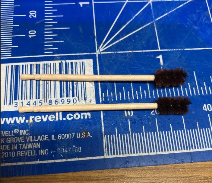
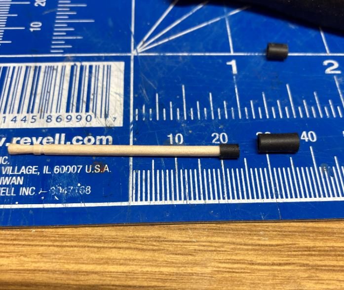
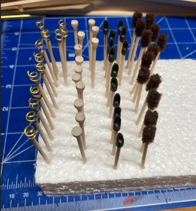
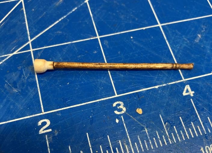
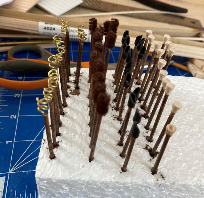
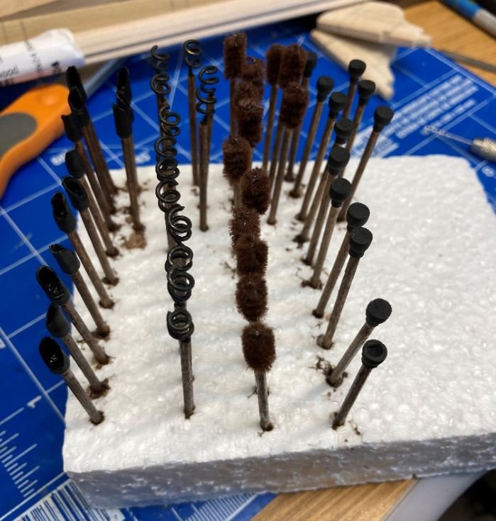
Hello again Everyone, Once again slow going, but I figured I'd go ahead and throw out there what I completed this time around. Forward armor plating of the casemates and hawse pipes were completed. The armor plating similar to the port and starboard sides. This side was a little trickier as the rivets weren't all in line so it made it a little more complex to get them all placed correctly. Next up were the junior officer quarters. Again more research was done to determine how these rooms were constructed, and again my research turned up nothing. I consulted with the group building the St. Louis and their research was inconclusive as well. They did say that the area was possibly set up as a soft walled, "tent like" construction that could be easily taken down and stowed when needed, but there was still no hard evidence that this was the case. So once again I took my builders liberties and used the HSR drawings as my basis for their construction. The HSR show the outline of toe boards where the walls were made with wood construction. I did however deviate from the plans a bit. The drawings show four rooms on the starboard side and five on the port side. Since I didn't thoroughly think this out before putting the cutaway on the port side the extra room on the port side would block the view of the paddlewheel from the inside. So I decided to leave that room out to give a somewhat clearer view of the wheel. Very little of these rooms will be seen, but I wanted to add them just for the added detail. Here is the construction of the rooms before being installed. And here they are painted and installed. Next were some more of the interior walls. This particular one was for the port side of the paddlewheel house. I left it open, exposing the timbers so that it will be possible to see the paddlewheel through the viewport. Wall temp installed. Wall with the paddlewheel in place. The way these are constructed there is no way to put the wheel axle in from the sides, so I am going to have to build all four walls and install them and the paddlewheel in one assembly. Another part I didn't quite think through. It's all good though, I think I can manage. Up next was the construction of the cannon implements. This was just a standard set of Naval cannon tools used on most Navy vessels during the 19th century. So I built up 13 sets of ramrods, bore worms, barrel swabs and powder cups. For all of these, I made the handles from decorative toothpicks. The worms were made from brass wire coiled and cut. A small hole was drilled into the end of the toothpick and the wire inserted and glued into place. The ramrods were created using a filed down Xacto blade and turned on my lathe. These pieces were then glued to the toothpick. The barrel swabs were made from a brown pipe cleaner. Part of the fuzzy material was removed to expose the center wire. Again a small hole was drilled in then end of the toothpick and the pipe cleaner glued and inserted. Finally up were the powder cups. These were made from heat shrink material cut and shaped to form the cup. The complete set of implements. Next I stained all of the handles then painted each of the ends. All done. A while back I had started work on the rudders, but never finished them. So it was time to get them completed. I am glad that I waited for this step, since making my discovery on how to simulate the rivets. I used this method to simulate the rivets on the pintles or the gudgeons (I always get confused as to which one is which). Gudgeons/Pintles drilled. I drilled the holes completely through the rudders so that I could use the styrene rod to hold the brass straps in place. All rivets completed on both rudders. Finally a little red oxide paint and we are done. That is all for this update. Hopefully next time I will have more. I did get an email yesterday that my cannons should be ready sometime next week, so hopefully I can get those in and start rigging them to the carriages. Once those are done and the captains quarters and heads are built I will be getting pretty close to closing things up on the gun deck. Not trying to rush things, just getting excited about moving on to the next deck. Until then, thank you all very much for the kind words and likes as well as stopping by to visit my build. -Brian
- 739 replies
-
- 16
-
-

-
Eric, For what it’s worth, I think you made the right choice going with the sail unfurled instead of stowed. The extra weathering added a nice touch to it. With the sails set and all oars locked in place, she’s going to be a beautiful display. As for your poor mans lathe, I still turn all my yards that way, or any piece that requires a taper. I feel that I have more control with the sandpaper than when it’s in my actual lathe. -Brian
-
Daniel, it just amazes me as to how much detail you can put into each and every little segment of the this build. Truly fascinating. It’s a joy to watch you work. -Brian
-
Keith, I wouldn’t call it impatience, I would call it a photo of you test fitting the spars to make sure they look authentic and fit correctly. 😜 Good thing the model police weren’t watching, I’ve been guilty on numerous occasions of jumping ahead and “dry fitting” parts before they are ready to be installed. It’s part of the fun. The photos show that she is really starting to look complete and how beautiful she’s going to be. Keep them coming. -Brian
-
Keith, Beautiful job. She’s really starting to come together. Almost to one of my favorite parts of the build, the rigging. It definitely looks like there is a ship emerging from the shadows. -Brian
-
Sails look great Eric! So for your reinforcement lines did you use paper as well or a different material? I’ve never used pastels before in modeling, only a looong time ago in high school art class, but I do remember thought that it was a pretty messy medium. I’m curious as to how you keep the colors from smearing while handling the sails without a protective coating sprayed on them. I’d have my reds, yellows and browns smeared all over the place. Probably even on models I’m not even working on yet. -Brian
-
Wefalck, This is just beautiful precision work you have going on here. I have been eyeballing a mini milling machine for several years now to try my hand at metalwork, but I just can’t seem to fit it in the budget. For now my mini wood lathe will have to do. ...but one day. -Brian
-
Johann, Simply amazing and precise work. A true pleasure to watch your work. -Brian
-
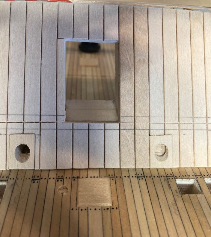
George, Always glad to help out. I used a pin vise when I drilled these out. It’s a little tedious, time consuming and tends to cramp the hand after a while, but given its close proximity to the gunwales I didn’t want to risk getting the drill misaligned and drill through the planking. I did forget to mention that I did all this after the comings and decking were in place. It was one of those “aww crap” moments I had not long after the top rail was glued down. -Brian
- 602 replies
-
- 1
-
-
- Flying Fish
- Model Shipways
- (and 2 more)
-
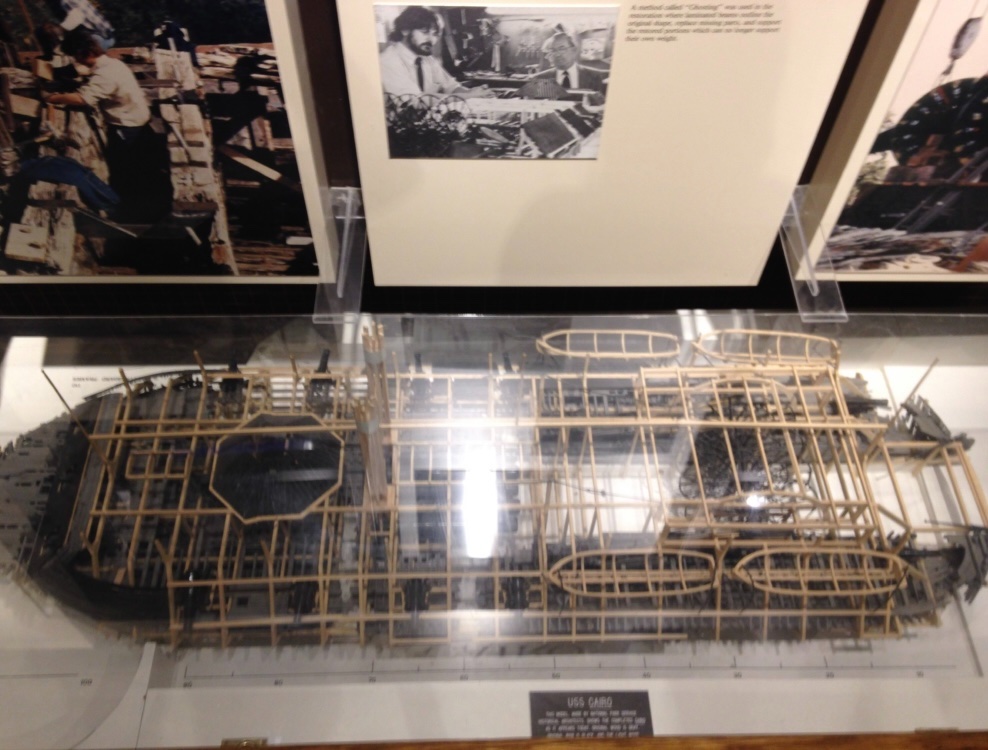
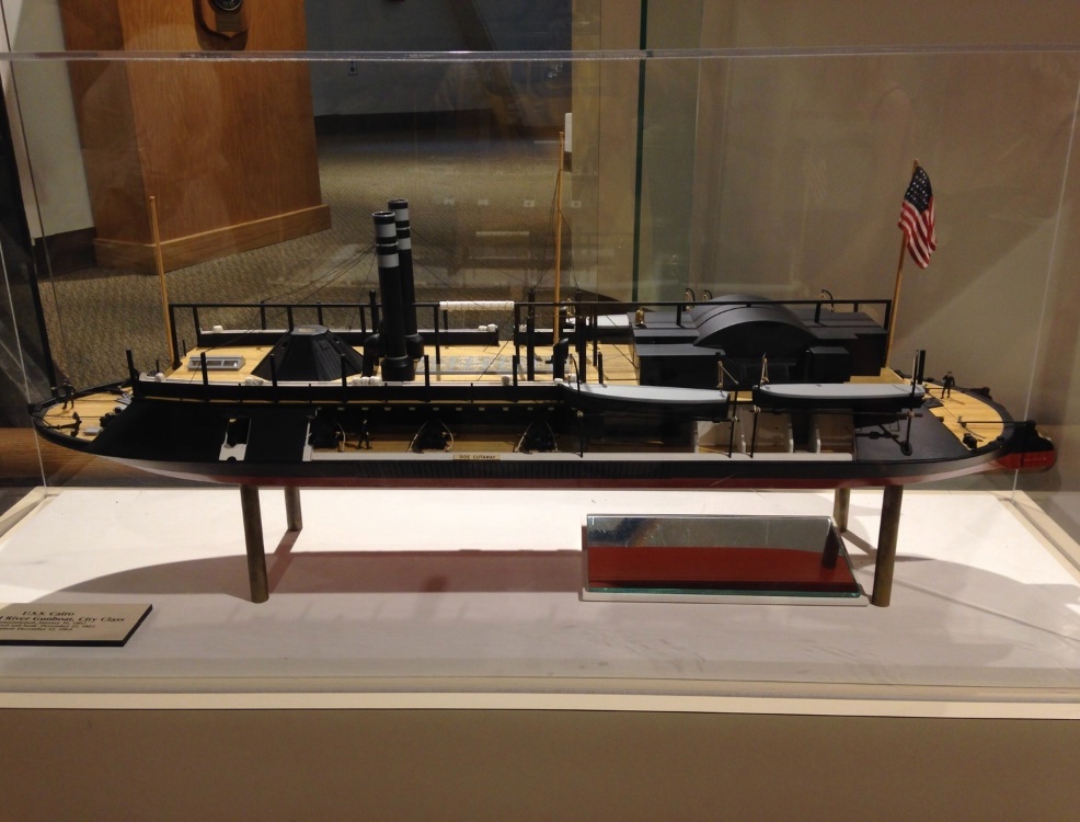
Thank you for the kind words George, this one will be for my own personal viewing. Not quite sure it would be up to museum standards. Not to mention the Cairo museum already has a couple of scale models on display. One is a model of how she sits in her permanent full size display and the other is a cutaway version. Both beautiful models. -Brian
- 739 replies
-
- 14
-
-
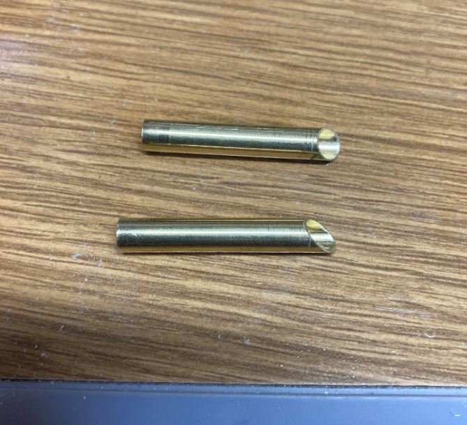
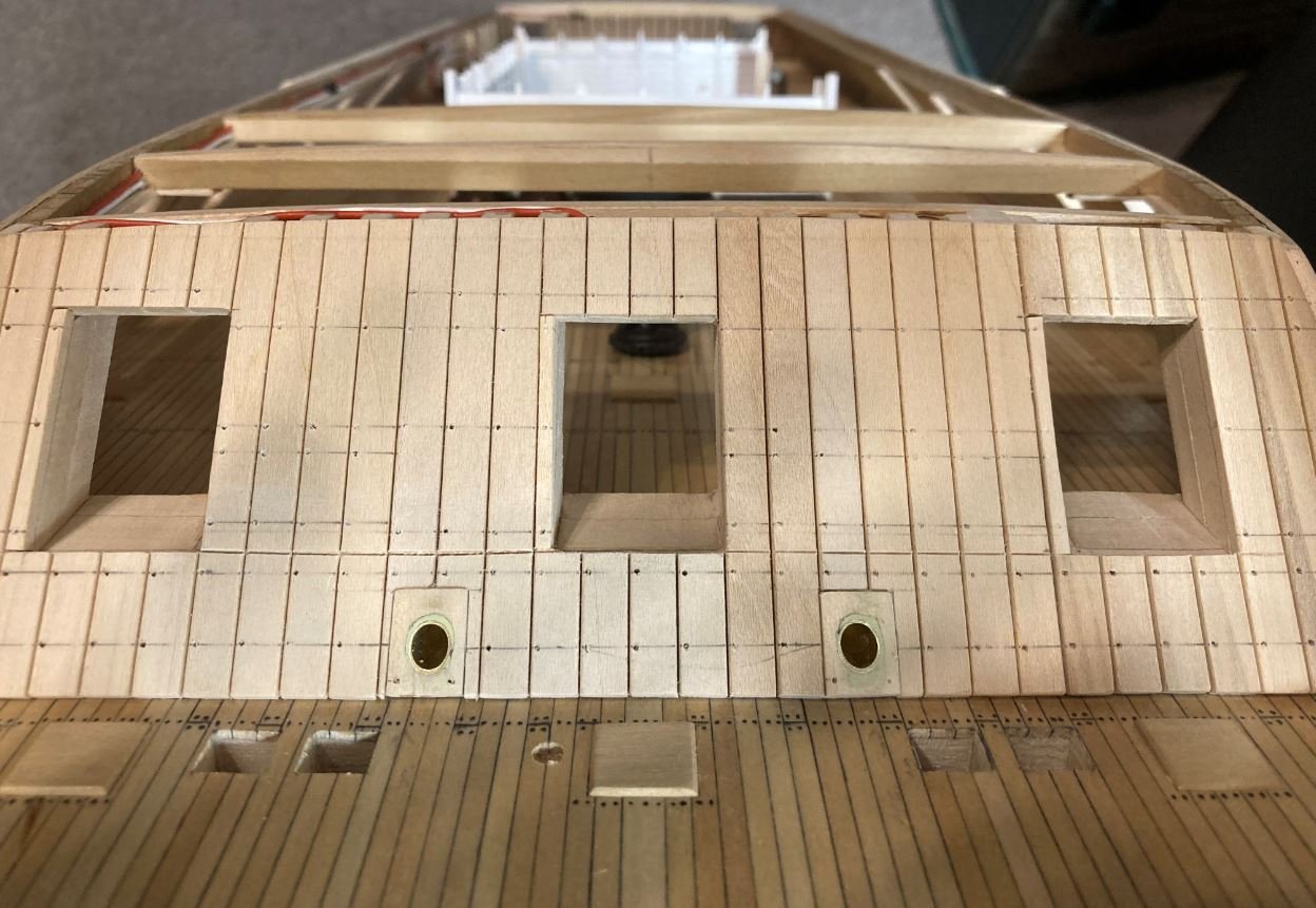
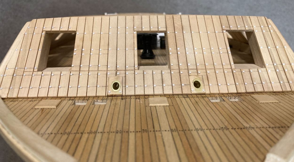
George, Love the green scheme. I went with the traditional black with white trim on my build, but I like the way the green stands out. It adds a nice touch of uniqueness to her. I want throw this out there. It’s been a while since I was at this stage on my build, and I don’t recall what the instructions dictate, but if you are planning to install the hold vent tubes, now is the time to do it. I remember struggling to drill the holes and setting the tubes because I had installed the top rail first. I can’t remember if I got ahead of myself and put the rail on first or if that was the way the instructions call out the assembly, but they are much easier to place while you still have everything open. Just a thought. -Brian
- 602 replies
-
- 2
-
-
- Flying Fish
- Model Shipways
- (and 2 more)
-
Eric, IMO I’m with Steven on this one. I would think that the shields would tend to get in the way if they were stored in the benches. However, if they were mounted on the gunwales it looks as though they may get in the way of the oar ports. Not sure if this is just the camera angle deceiving my view. On the other hand, you could do a mixture of both, but I did like the idea of placing some of them along the cradle. -Brian
-
Keith, the warmer weather does tend to put a slowdown on the building. As much fun as it is, we still need to shed that winter coat and enjoy the springtime and work on the other yards. Yards (ship wise) are looking great though. We are a patient bunch, so enjoy the outdoors. -Brian