Ian_Grant
-
Posts
2,156 -
Joined
-
Last visited
Content Type
Profiles
Forums
Gallery
Events
Everything posted by Ian_Grant
-
 Bill, better check on gunport lid tackles - not sure if 17th century French ships had two lanyards or just one. Someone here will know better than I do.
 -
Nice. I would cover it in a high gloss finish to protect the shading, then apply a dark wash to fill in the caulking lines. After all is dry, cover again in satin or matt clear.
-
I must confess that I simply tied the 2mm blocks to eyebolts on the gun carriage and bulwark, omitting hooks. That way there is a space between the blocks. At 1/100 nobody lacking a magnifier will ever see the difference especially on the "visible" guns on the main deck under the gangways.
-
Bill, the best sized source for the cannon tackle blocks is 2mm singles and doubles from Syren......... oops, I checked and they don't seem to make them now........never mind.........
-
Yes, it was annoying but they probably had elderly stroke victims arriving by ambulance. It may be amusing to hear of the ER process I encountered; if not you can just skip this post. On walking through the door I encountered a check-in desk of sorts. She asked what is the issue and I told her I'd cut my finger and needed stitches. "Do you have your health card with you?" (I pass it over). "Are you still on xxxxxx Crescent?" (I reply in the affirmative). "Still at 613-xxx-xxxx?" (Yes, that is my number). "Thank you. Have a seat until your name is called". An indeterminate amount of time later I hear my name and approach an open door where another nurse awaits. She leads me to her workspace and hooks up a blood pressure sleeve and a finger tip oxygenation sensor. After taking my temperature, she asks: "Do you have your health card with you?" (I pass it over). "Are you still on xxxxxx Crescent?" (I reply in the affirmative). "Still at 613-xxx-xxxx?" (Yes, that is my number). She then unwraps my wife's guaze handiwork and quickly moves her garbage can under my dripping finger to catch the blood. She confirms stitches are needed and rewraps it. She then sends me off with "They'll probably want to see this soon to stop the bleeding. Have a seat outside 'til they call your name. An indeterminate amount of time later I hear my name and approach intake desk #4 where a third nurse greets me: "Do you have your health card with you?" (I pass it over). "Are you still on xxxxxx Crescent?" (I reply in the affirmative). "Still at 613-xxx-xxxx?" (Yes, that is my number). "All right. They'll be with you shortly; just have a seat until you hear your name." An indeterminate amount of time later I hear my name called along with three others. We all approach a large door and are ushered into the actual ER. "FInally" I think. It's been more than 5.5 hours since I arrived. "Ian, you're in exam room #10. The doctor will be with you shortly". Another hour passes. I stroll out and ask the ER nurse if she knows where I am in the line. She says "Fourth right now". I return to room #10 and my Sudoku book. After another half hour I ask again. She glances at a screen and says "Fourth right now". I return to room #10 and throw my crossword and sudoku books in the garbage bin - I've been through them and through them and done all that I can without looking at the answers. I doze off sitting and leaning back on the wall. Half an hour later a doctor enters and startles me awake. "Hello Ian, I'm Dr. xxxxxxx". "Do you have your health card with you?" (just kidding; she didn't ask about any of that). Finally treatment is provided. It's been more than 7.5 hours since I arrived. ================================================= Our family doctor is about our age and so is near retirement. When she goes, we'll be without an MD just as we enter our senior years. Not a pleasant prospect given the tens-of-hours wait-time horror stories recently in the news. One poor fellow waited in a stretcher in a hallway for more than a DAY to get a broken leg attended to!!!! According to a recent CBC news report, they took the time to comb through the list of family doctors in Ottawa and found exactly three out of more than 1200 that were taking new patients. Everything in Canada seems to be falling apart at once. https://www.cbc.ca/news/canada/ottawa/ottawa-family-doctors-new-patients-shortage-1.6643412
- 536 replies
-
- 2
-

-

-
- Quadrireme
- radio
- (and 1 more)
-
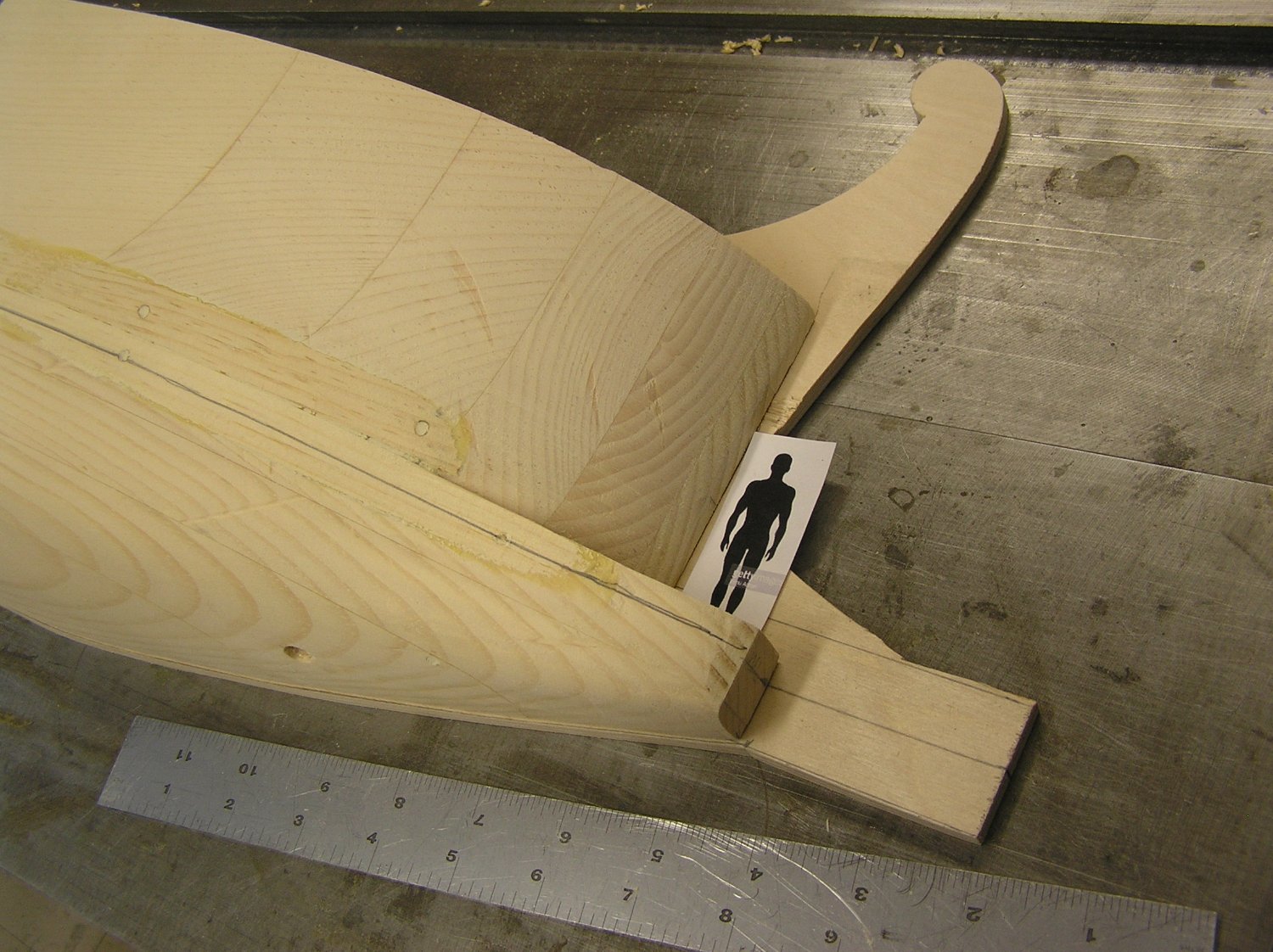
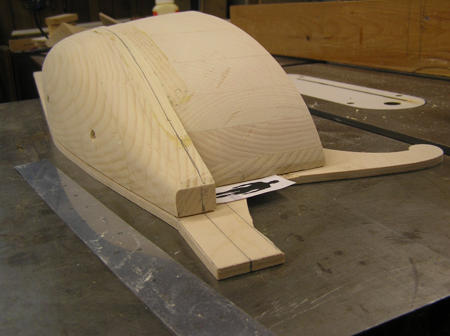
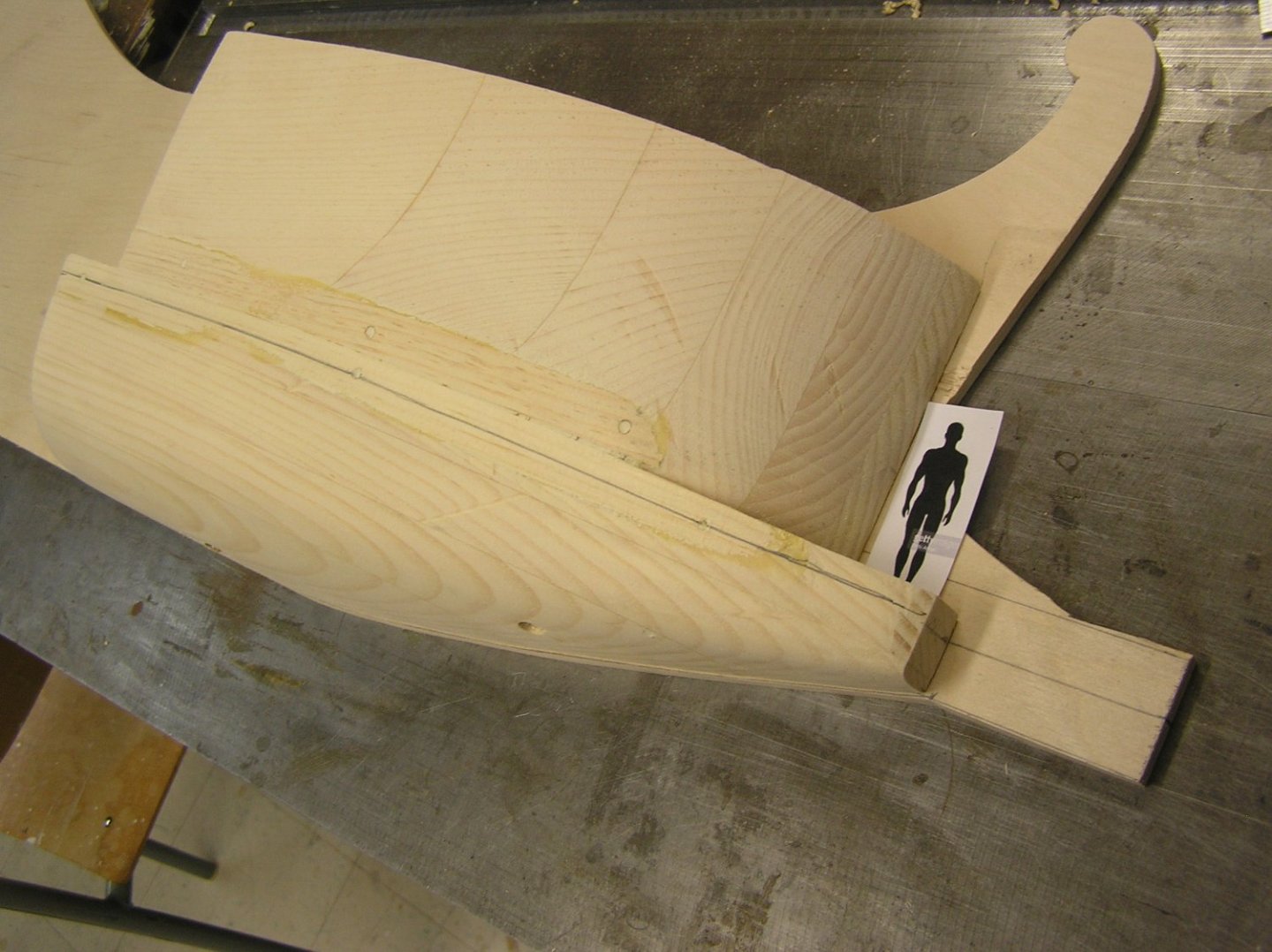
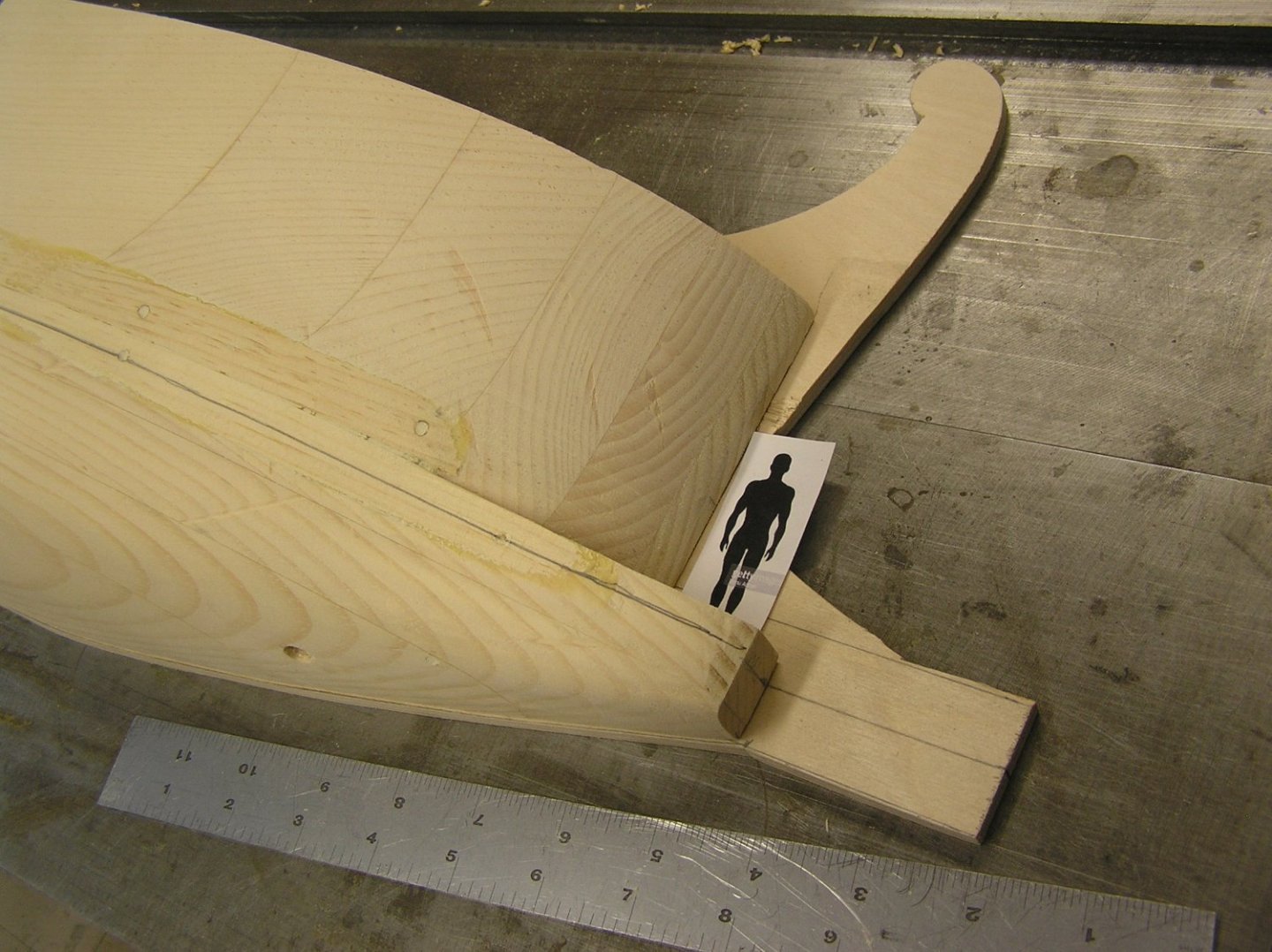
I have a half-hull model for the business end. I did it in two parts, the u/w and above-water hull but when I wedded the two they did not meet so perfectly fair-curve wise. I had to glue on a couple of 1/8" thick strips along the join to plane down to suit. Anyway here are pics. "Julius" is a 1/32 scale human outline. I have been searching for crew figures but it seems they will not be easy to come by. I've never done resin casting but apparently that is what people do - buy a couple then cast copies, perhaps with separate legs and arms to glue on for variety in the poses. Yikes! The pencil line is the waterline, at the midpoint of the ram. Where Julius is standing there will need be to be a "fairing" angling up to the stem; plan is to skin the hull u/w and above then fill in this fairing with solid. Hoping to skin in 1/32" ply to avoid planking and fiberglassing. After all this is for R/C not scale display. 😏 The upward sweep of the bulwark at the stem is not represented here but of course will be built. If ever I do this again, and I hope not to, I will glue up the blanks with thinner layers - I just slapped together standard 3/4" pine. While sanding I noticed that the joints between the layers give an indication of your buttock or waterline contours (depending on which way you glued up the layers) which could be used for fairing. Now to the stern....... ps - don't know why the extra blow-up image, can't seem to delete it.

- 536 replies
-
- 4
-

-
-
- Quadrireme
- radio
- (and 1 more)
-
Kevin, that's a brace for the trussed LT yard - see Underhill pg 80 Plate 18 middle sketch. Also Plate 15 pg 72.
-
Neither is correct. As far as I know no ship had capstans paired across the centreline. Dafi had a post about this Hellerism too, advocating correcting to two capstans on the centreline. But they will never be seen, or even used if you follow the usual practice of looping an anchor cable in one hawse hole and out the other. Don't waste any worry on them.
- 1,508 replies
-
- 2
-
-
- Le Soleil Royal
- Heller
- (and 1 more)
-
That's an enviable record. I've had stitches twice now, in 40 years.
- 536 replies
-
- 2
-
-
- Quadrireme
- radio
- (and 1 more)
-
Thanks, gentlemen. The doctor asked how it happened. Went away and came back with the freezing stuff; asked if I'd had stitches before. When I said yes, she replied, "Yes, everyone that works with saws has had stitches" Haha.
- 536 replies
-
- 3
-

-
- Quadrireme
- radio
- (and 1 more)
-
Yes, it's weird that only the main mast extends to the keel while the others stop on decks. Not like their Victory. Bill, your stand is beautiful. And the hull painting looks great. Looks like SR may eclipse even "Victory". 😄
- 1,508 replies
-
- 2
-
-
- Le Soleil Royal
- Heller
- (and 1 more)
-
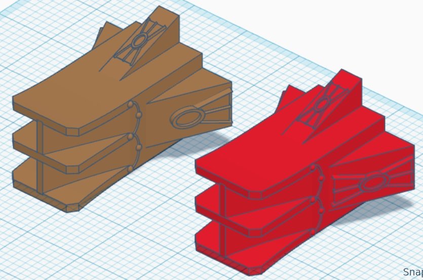
Well I have discovered that my best effort cannot produce a fair hull on a drafting table. I thought if I had actual size profile, top, and cross section views all properly aligned on the sheet I could do it, but I can't. If for example I draw fair looking curves in say the top view, they might look ok but translated to the cross section they are not fair. I did a lot of erasing then decided I do not know what I am doing. At least I got actual size bow and stern profiles and waterlines out of it. I traced the bow and stern profiles onto some true 1/4" ply I had around. I will just cut these by hand instead of having to do the keel in 24" sections for the laser cutter. The bulkheads will be lasered for accuracy & consistency. I reverted to the plan of carving half-hulls at the bow and stern which I will simply slice up and use to trace the bulkhead contours. I did the u/w bow first and quickly discovered that my waterline and u/w profile which looked ok on paper were way too bulbous; the effect of carrying on from the bulky midship section. I reduced it to what I think looks pretty good. Then I glued up a blank for the above water hull at the bow. While hogging off the waste with my bandsaw I stupidly cut my index finger pretty good - the classic "following a curve then having the hand slip". I went to the ER last night and finally had five stitches this morning at 6am. I did not want to go there, knew it would be bad, but the bleeding just was not stopping. Let me tell you, I was pretty sick of sudoku and crossword puzzles after seven hours of waiting! 🙄 Rather than stress my stitches by using a hand plane today I thought I would sit quietly and have a crack at drawing a ram in TinkerCAD. Here are a couple of results. I added some decorations as found rams had some but TinkerCAD doesn't have such things as acanthus leaves sadly. I used the limited shapes available; not sure which I like better. The upper and lower horizontal vanes curve apart slightly. The front is about 1.25" on a side. The angles on the sides are where the main wales come in, while the upper angle is for the stem. Don't know if the decorations would actually print, other than in resin. Oh well.
- 536 replies
-
- 3
-
-
- Quadrireme
- radio
- (and 1 more)
-
Never heard of Belbin before. Judging by the summaries, I'm more of a specialist/finisher. Good traits for engineering. And model building. 😃
-
Looks good Bob. I again recommend that you add a brace across the rudder tubes, like the one you have on the prop shafts. Looking forward to your RC test, in particular to hear if there is any hum/tone audible when motors/ESC run.... I did exchange emails with "Big Rich" about rejuvenating my old boat. Looks like new brushed ESCs with my old Decaperm motors is the way to go, providing that those old motors are ok. Plan to lube them and try them out.
-
Actually the fairleads align with the sheet block. They're on the bottom of the yard.
-
Kevin, the cheek blocks should be at the back of the yard not the front. From here, the sheets run through fairleads at the bottom of the yard to your lovely sheet block. Once you have the cheek block at the back this makes perfect sense. You're getting to be quite the 3D resin guy! I'm impressed you were able to drill through the yard axis for such a length! This model is going to be rock solid. When will you be marketing your tru-to-life rendition of Cutty Sark? 😀 ps I think you are are referring to the studding sail booms (stuns'l booms) as "yardarms".
-
Bob, just noticed your boat has twin rudders. I recommend you glue in a brace across the hull near the top of those two plastic rudder tubes, to reinforce them. Digression: in the 70's I made a Class M RC yacht (50" LOA) and the instructions said to epoxy in a block of wood inside the fiberglass hull through which to drill the hole for the rudder tube. Can't imagine why now but I used balsa wood. I sailed that boat for about a decade. A few years ago I thought it might be fun to fix her up and sail her at the cottage. She was running well directly away from me on a reach when I realized I could see the top of the deck, somehow. How could this be?? ........ She was sinking by the stern because the balsa had let go from the bottom of the hull and water poured in. The lead keel bulb took care of the rest. Luckily we are in a fairly shallow bay (20ft at deepest) so I snorkeled out and managed to find her on the lake bottom. Amazingly the RC stuff was fine after being packed in rice, but the battery was wrecked. Fond memories.
-
Bob, thanks for the reference. I will check out the web site. You're definitely going with a brushed setup, so you don't need to worry about KV or T which only applies to brushed motors. 4S, 6S etc refers to the number of cells in a lithium or nickel hydride battery pack, as an indication of battery voltage. A given voltage requires a different number of cells for these battery types since the chemistry of the basic cells differ and so does their voltage. This is all new to me too as back in the day I used lead acid or latterly gel cell. Looking forward to your build. Is the hull plastic?
-
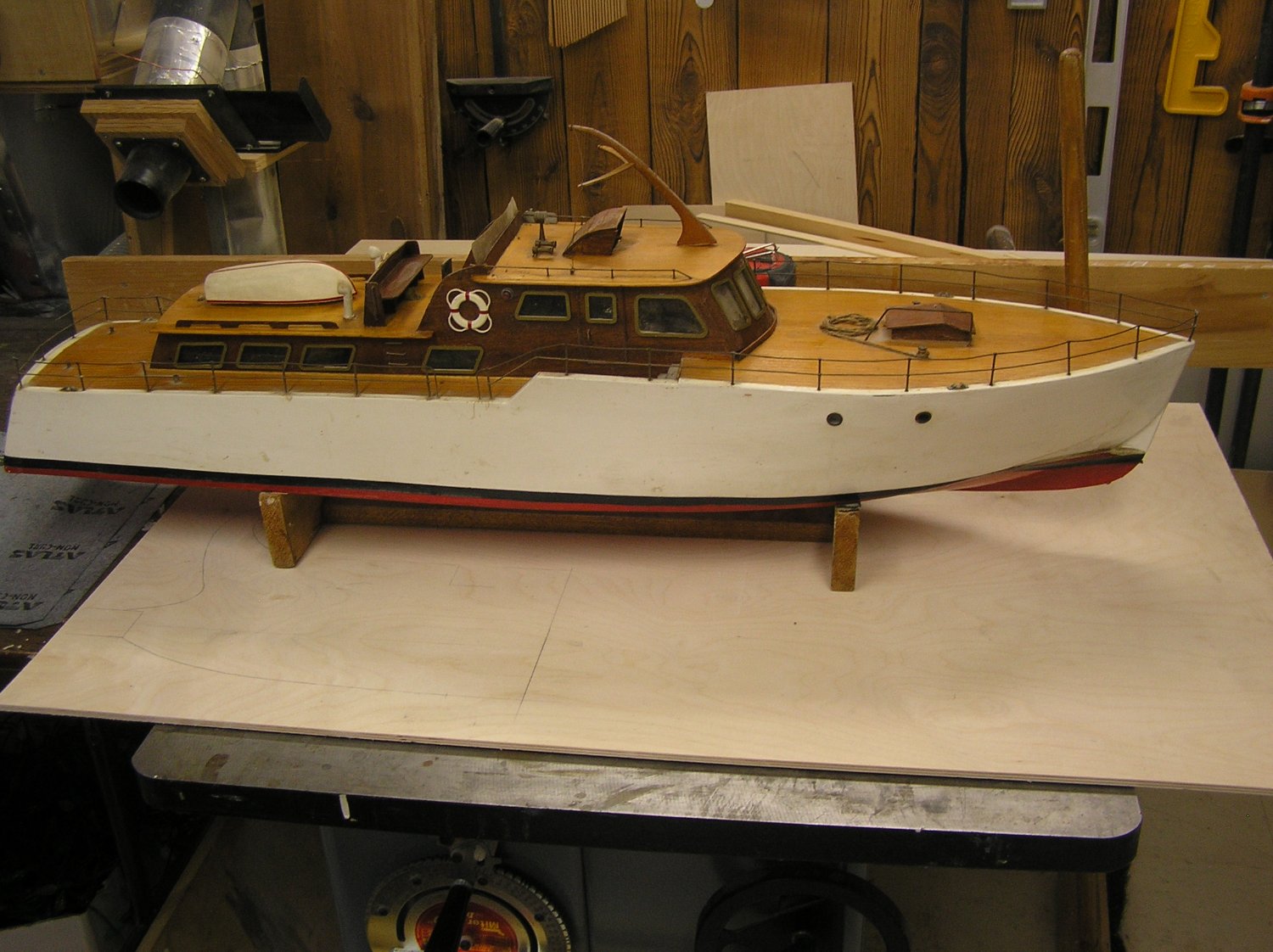
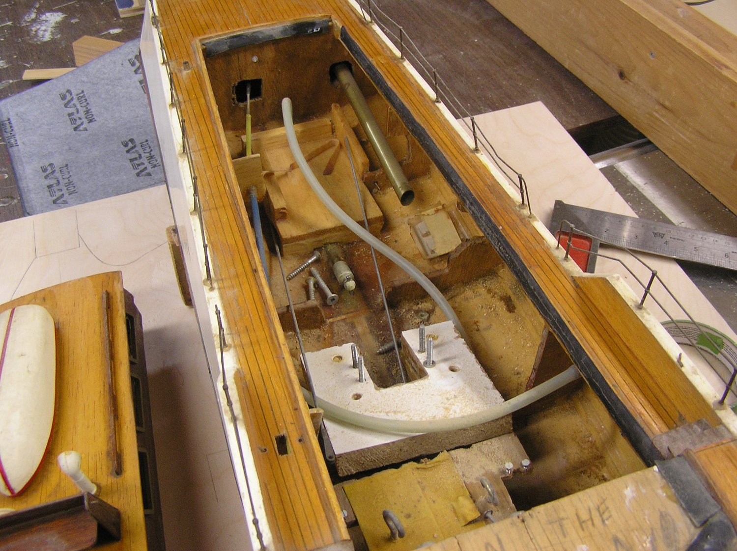
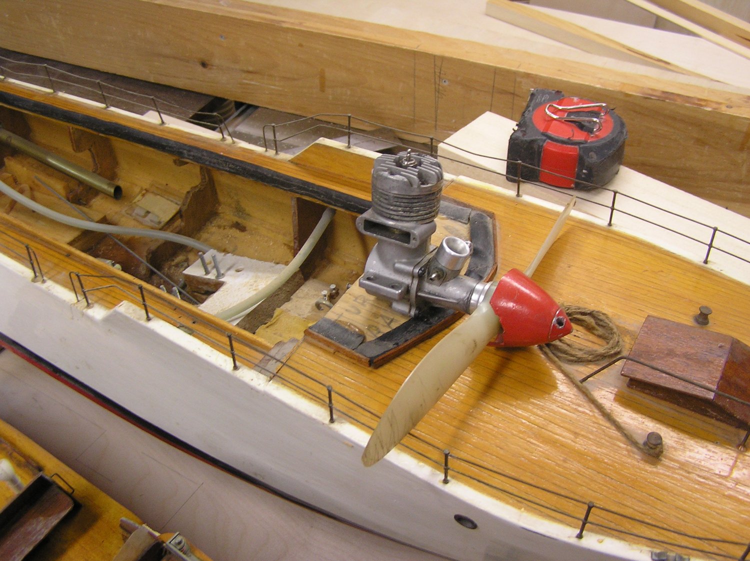
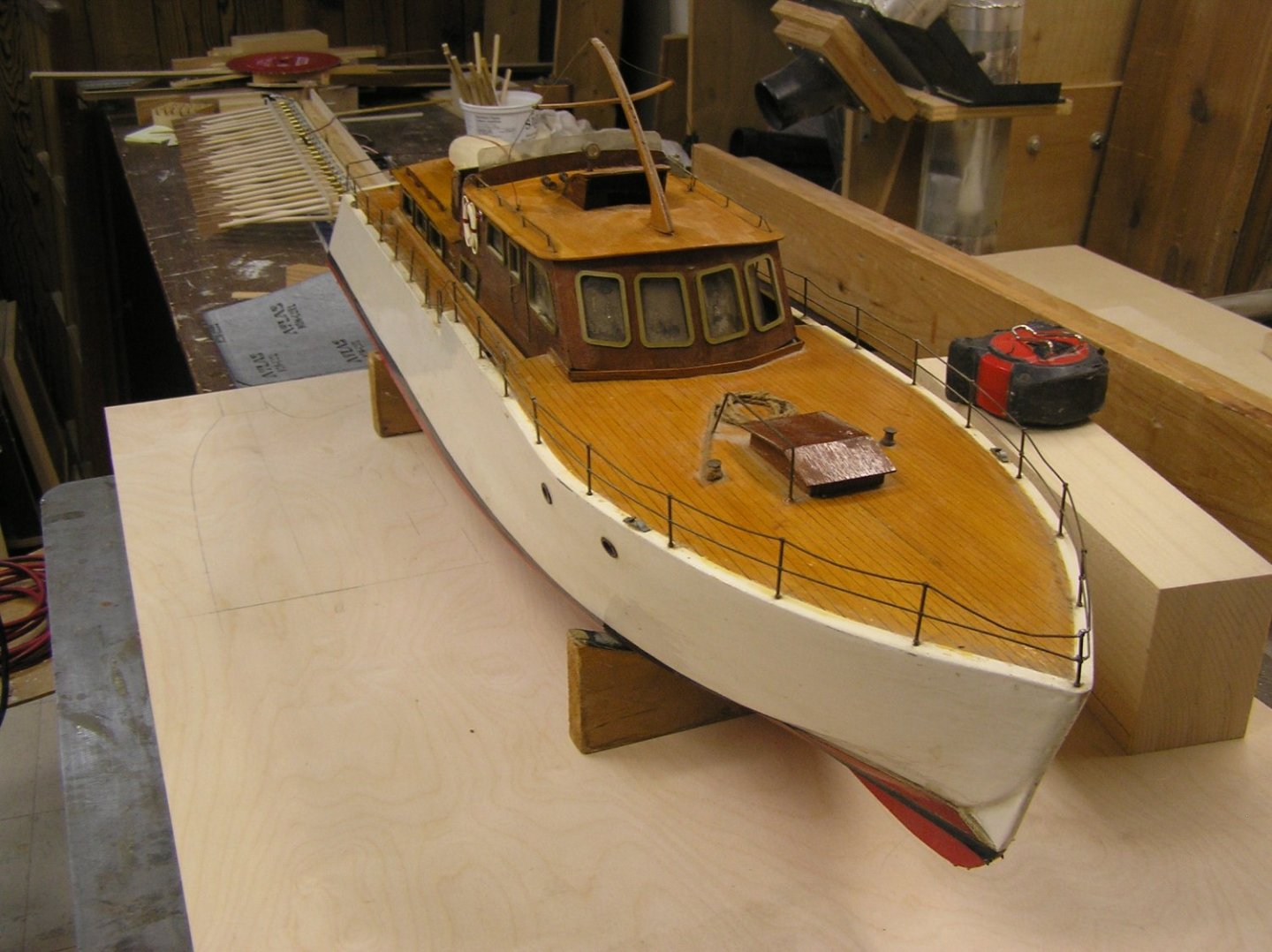
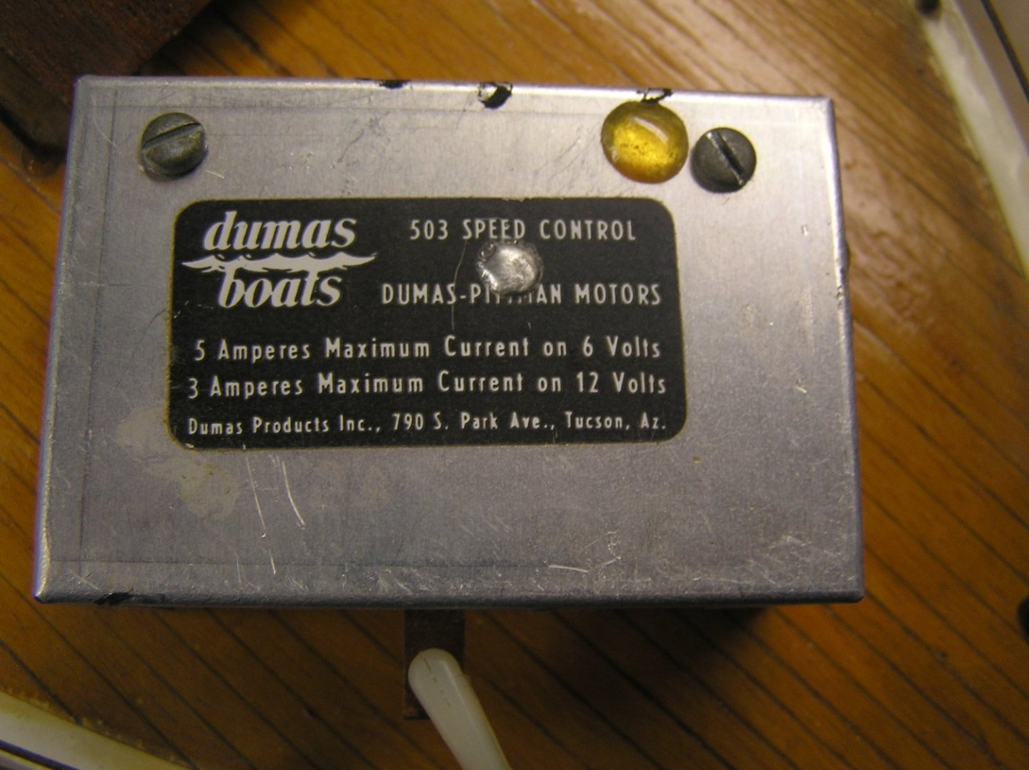
Bob, nice boat, nice project. In high school in the 70's I used to launch a new RC boat every spring. This Constellation is a little like my old Billing Boats "Admiral" cabin cruiser. I'm interested in your new RC gear; are those brushless motors or brushed? If brushless, how did you select the KV and T specs? The modern ESCs are a far cry from the old rheostatic speed controllers I had to use. What a waste of power! After getting back into model ships a few years ago with static builds I decided to try RC again, with a scratch Roman galley in progress. I'm also considering a refit on my scratch WW I battlecruiser (that was my build before grade 13), wondering whether to buy brushed ESCs to use with my old motors or go all brushless. But I find the brushless motor specs very confusing.....KV.....T.....4S-6S...???? I wouldn't know what to select as replacements for my old decaperm motors. All the web seems to talk about are motors for speed electric boats not scale. All my local hobby shop knows is cars.😢 Looking forward to your build. As Chris says there are too few RC boats here. Here are some pics of my "Admiral". She has a hard chine hull so the entire skin is four pieces of thin ply. I just cleaned off most of the dust for the pics. Wish I had painted the black stripe instead of using electrical tape 😬 it was always coming unstuck at the stem. The last pic shows the 0.35 gas engine I mounted in her with water cooling adapters at one point - not with that prop obviously - the keel came out of the water about halfway back from the bow! Had trouble keeping enough air flowing to the engine too; there's a big brass tube under the bench seat as an air inlet. You can see another brass tube inside, which was the exhaust out the transom, after the muffler. Fond memories......


-
Resellers, ... BAH ..(spitting on the ground). There's always a fly man ready to grift a buck.
-
Hi Glen, that's called "tumblehome". Kept higher-up weight nearer the centreline, for stability. You're on the way to another triumph! She looks great!
- 134 replies
-
- 2
-
-
- Captain Kidd
- bottle
- (and 3 more)
-
Awesome! I've been aboard once but never seen her under sail. Amazing to think she still sails at her age. When I took my family there maybe 15 years ago they were talking about a refit to put camber back into the deck, undoing a previous refit which put down a flat deck for some reason. Or did I mishear the story?
- 1,508 replies
-
- 1
-
-
- Le Soleil Royal
- Heller
- (and 1 more)
-
I'm sorry; are we talking about model kits or concert tickets? Look out for them on resale sites.