

bruce d
-
Posts
3,046 -
Joined
-
Last visited
Content Type
Profiles
Forums
Gallery
Events
Everything posted by bruce d
-
 Hello George, What a great subject, well done. I saw an image of something similar on Thassos a few years ago but there was no date. I will watch if you don't mind? Καλή τύχη Bruce
 -
La Real by sotter - 1:150 - from Dusek plans
bruce d replied to sotter's topic in - Build logs for subjects built 1501 - 1750
Looking good, mind if I watch? -
They are invaluable. Also, they are cheap: https://www.proopsbrothers.com/modellers-hobby--craft-kit-plastic-parallel-slide-clamp-130mm-x-50mm-large-3092-p.asp ... and available in smaller sizes... https://www.proopsbrothers.com/modellers-hobby--craft-kit-plastic-parallel-slide-clamp-75mm-x-40mm-small-3095-p.asp Their ebay store has multi-packs of 5 and 10 at discounted prices. I have no connection with Proops other than being a long term satisfied customer. HTH Bruce
-
Hi Thomas, sorry for the delay in answering but it looks like you chose well. Your progress is good and you seem to be doing all the right things. The stern looks better after you thinned it down and the stem (that piece at the bow) looks alright to me (but I haven't seen the plans ). The stem is quite a big part of the distinctive appearance of these craft and I have spent quite a bit of time finagling the stem pieces on my Mediator.
-
Yard height on 18th century Cutter
bruce d replied to michaelpsutton2's topic in Masting, rigging and sails
Hi Michael, Actually, the cutter is English, purchased by the Danes. Since starting this thread ... ... I have narrowed things down a bit more. There are a couple of files which I believe will help once I can return to The National Archives (I don't have the guts at the moment). HTH Bruce -
OK, have a look at this and compare the end grain of your wood with the examples in the video. If your walnut is quartersawn, you should be able to get good slices off the narrow edge. If not, you will have to experiment. Based on my own experience, and I am no expert, you will know pretty quickly if thin planks from the narrow edge are going to be any good. HTH
-
Hi Thomas, looking good so far. Just another unsolicited bit of advice: choose your filler to match the hardness of the wood surface. If one is harder than the other, sanding will be much more difficult because each stroke will remove more of the the softer material (whether it is the wood or the filler) and leave high spots and low spots. On the curved surface of a hull, the effect is even more pronounced. If anything, go for a filler that is softer than the wood. HTH Bruce
-
Yard height on 18th century Cutter
bruce d replied to michaelpsutton2's topic in Masting, rigging and sails
Michael, no straight answer from me but is this any help?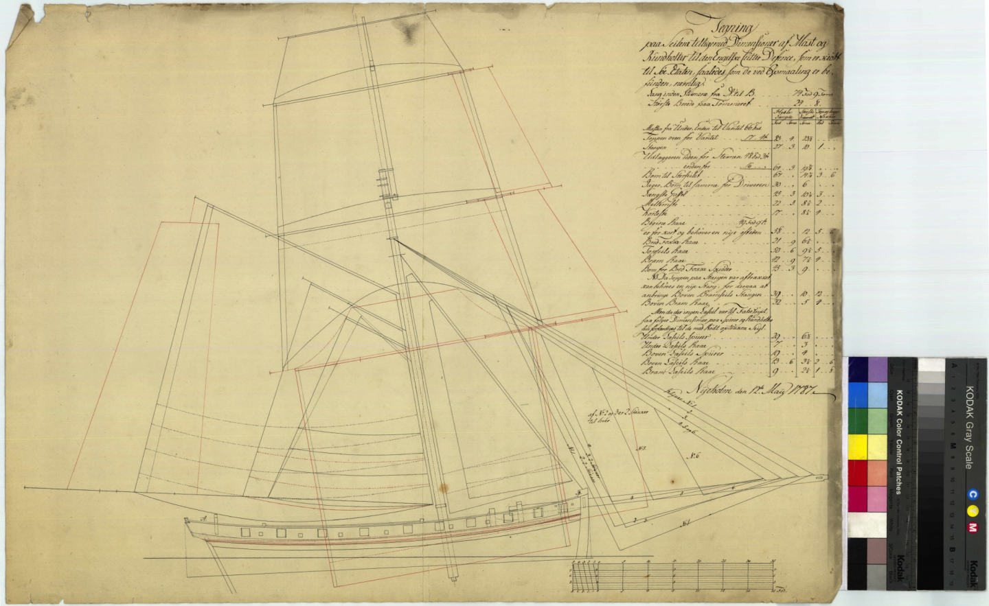
-
Chronos have very good aftersales service.
-
Thanks Mike, keel update soon. If it is of interest, here is the link to the thicknesser used for the tapering: HTH Bruce
- 43 replies
-
- 3
-

-
- mediator
- first build
- (and 1 more)
-
Depends what you want to do with the saw. Chop off saws are good at, well ... chopping off. The Proxxon FET saw ... https://www.chronos.ltd.uk/product/proxxon-fet-table-saw-240v-210576/ ... is pretty good at most small tasks that suit a conventional saw-table. I have one, it is consistent and once you get used to the fence and mitre seems well suited to a modellers typical needs. It also of course can chop off wood using the sliding mitre. You will undoubtedly hear that the best saw on earth is a Byrnes saw: I am sure this is true. Sadly I do not have one so can only say that so far I have been satisfied with the Proxxon. HTH
-
Welcome to MSW
-
Always looking for problems solved by others before I come to them in my build. Good luck and maybe you could ask if the numbers relate to some linen industry standard? That seems to be the case but I'm guessing.
-
Hello Mike, I think this fits the description ... https://www.linladan.com/products/the-flax-flower-hemstitch-yarn?variant=21884453748841 ... for the 874 but no sign of the 870. HTH
-
Hello Slowhand, just looked properly at your log for the first time. A very interesting subject and the way you are keeping your cool while navigating the what-scale-is-it-today game is admirable. I will follow along if you don't mind? BTW, my Scheppach bandsaw only had one weak spot: the tyre wear which never made sense. The UK after-sales support was always first class. I have now upgraded to a Metabo BAS261 simply because I needed to do some bigger stuff.
-
You are my hero.
-
I love MSW. It has yet again made me think. So here is my question. If two pieces of wood are to be glued together, and one of the surfaces has been painted with acrylic paint, which glue gives the best result? Part two of the question: what if one surface has paper glued to it? (big hint: scarf joints, edges of planking)
-
By following this suggestion you will find the results of your wood, your glue and your sanding/scraping materials. All three affect the outcome and you may find that you just don't like carrying out a particular process despite liking the results other builders have produced. I sympathise, and a few experiments with the scrap wood from your kit will tell you a lot.
-
Laying out plans in a smaller workshop
bruce d replied to alde's topic in Modeling tools and Workshop Equipment
I admit when I got the first one I was wary of this but (maybe luck) mine stay put unless given a good wallop. -
Laying out plans in a smaller workshop
bruce d replied to alde's topic in Modeling tools and Workshop Equipment
My workshop has absolutely no floor space left so I couldn't use an easel as intended. The solution was a piece of 1mm steel sheet from the local blacksmith (£5) screwed to the wall above the workbench. It is big enough to take A1 size plans and magnets do all the work. For what it is worth, I have a policy of never putting shelves above a workbench (ask me how I know what can go wrong... ) and am very pleased with this arrangement now that it is in place. The picture below was taken immediately before beggining work on my Mediator and I assure you the bench does not look so clear now but the wall is unaffected by events below. A new trick I discovered: a short steel ruler is now always stuck on the plan with magnets, always there when I look for it. Also, the small LED lights with magnetic bases originally for use on the mill and bandsaw are very handy to attach in any position above the workbench so I am ordering a further one, a bit bigger. HTH, Bruce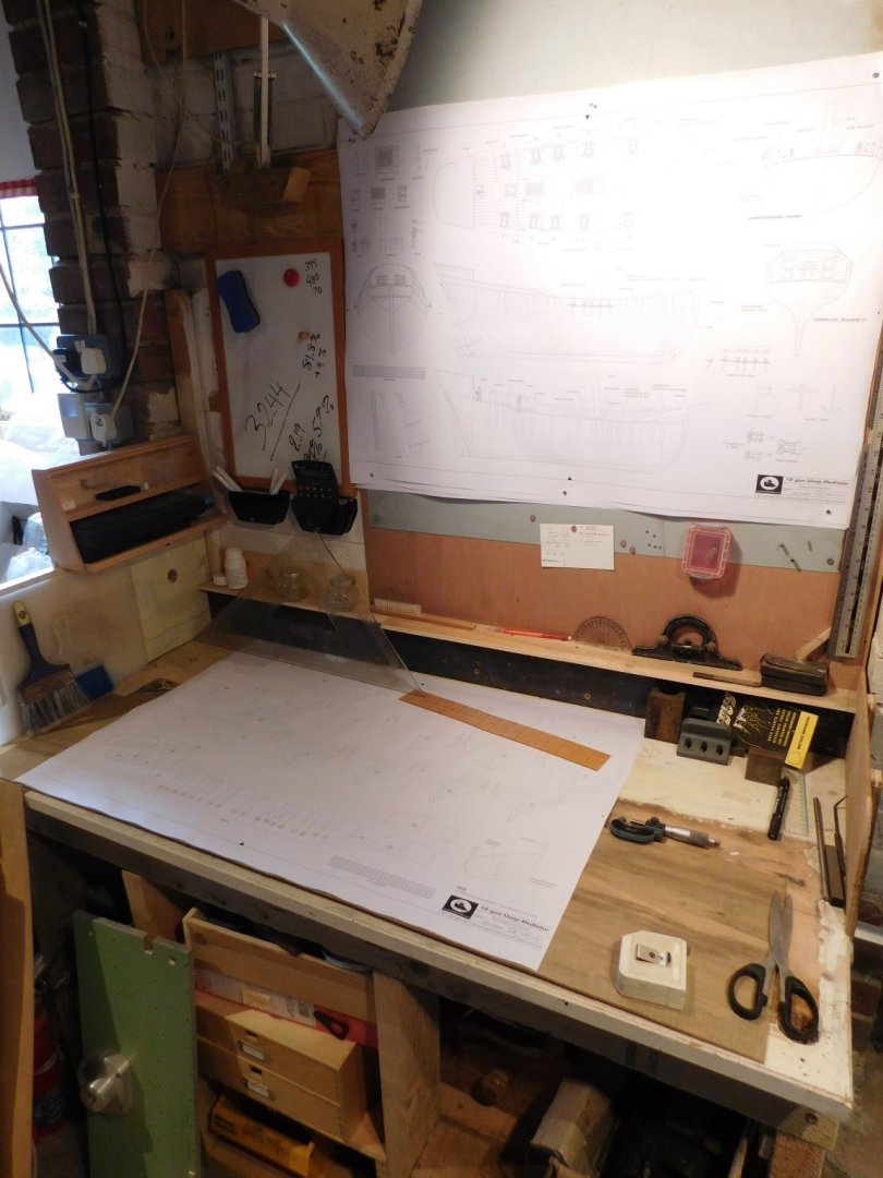
-
Sometimes the obvious needs to be said. Your way makes so much more sense than my 'take-the-paper-to-the-plank' attempts. Thanks, Bruce
-
Allan, I have been fiddling around with paper and so far I am making a mess of it. I really like the results others have achieved with paper and hoped it would pop up in this thread. Is there a description somewhere of how to get it right? Thanks, Bruce
-
Prynhawn da pawb - (Good afternoon all) from Wales!
bruce d replied to SweepHall's topic in New member Introductions
Welcome to MSW, looking forward to the Bounty. -
Welcome to MSW!

