bruce d
-
Posts
3,046 -
Joined
-
Last visited
Content Type
Profiles
Forums
Gallery
Events
Everything posted by bruce d
-
 And the workshop news ain't bad either.
 -
Welcome to MSW. Always room for someone who knows a thing or two about ships!
-
I wish I was as clumsy as you. ;D For no good reason I did not keep up with your log. Now, I have set aside some time this evening to read it from the start and have no doubt it will be time well spent. Well done Tony. Bruce
- 124 replies
-
- 4
-

-
- longboat
- Chaloupe Armee En Guerre
- (and 1 more)
-
Cutter Grace 1763
bruce d replied to tabycz's topic in CAD and 3D Modelling/Drafting Plans with Software
Druxey, can't help with that item other than to say it looks like it may have been the footprint of something else that is now missing. Next up, and hopefully more helpful, is this one: https://collections.rmg.co.uk/collections/objects/66542.html SLR0581 Description Scale: 1:32. A contemporary full hull model of a merchant brig (circa 1795), built plank on solid wooden core in the Georgian style. Model is decked, equipped and fitted with three sliding keels as designed by Captain John Schanck. The model has a number of working parts including windlass, winches, doors, pump, and rudder, all of which aided the publicity of the sliding keels principal when Schank was trying to sell his idea to both the merchant and Royal navies. The idea worked on the principal that when the keels were lowered, it improved the vessels stability and sailing qualities. It also enabled the building of ships with a shallow draught allowing them to undertake passages in shallow waters or for survey work. At this scale, the model depicts a vessel measuring 72 feet along the deck by 19 feet in the beam and a tonnage of 100 burden. The modelmaking is of the highest quality and is though to be by the hand of Allen Hunt, a top quality craftsman whose patrons included the Duke of Northumberland and high ranking naval officers. Date made circa 1795 The small structure enclosing the tiller head addresses the general question and I am pretty sure the structures either side are pens/coops for chickens and whatever critters were carried. Considering the nature of these pens it is perfectly reasonable that they would not appear on plans.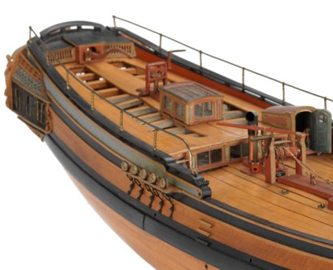
-
Kurt, the Aztek is a lovely airbrush and will make someone happy. I've got one. It is different from many other brushes but is intuitive, easy to clean and a quick way to get good results.
-
Cutter Grace 1763
bruce d replied to tabycz's topic in CAD and 3D Modelling/Drafting Plans with Software
Found this. This is a model in the NMM collections, item # SLR0416. https://collections.rmg.co.uk/collections/objects/66377.html The description says... "Scale: 1:48. Georgian full hull model, with elements of Navy board style, of a sixth rate 12 gun sloop (circa 1720). The open frames have been painted onto a carved pine carcass hull below the waterline. The model is predominantly in the Georgian style in that the decks are partially planked and includes a variety of fittings, such as a brass bell mounted on the raised folksal deck, a brick faced fire hearth below decks with a brass chimney, bilge pumps, capston and ships wheel mounted against the quarter deck bulk head. The hull is fitted ten oar ports between the gun ports and also includes detailed painted decoration on the scroll figurehead, bulwark screens and stern counter The model depicts accommodation and storage below deck as well as carved and painted decoration at the bow and stern. The model is mounted on a pine base on top of an ornate keel block and four turned feet below." It is dated "circa 1720" HTH Bruce -
Me too. Thank you Bob for raising the subject.
- 778 replies
-
- 3
-
-
- cheerful
- Syren Ship Model Company
- (and 1 more)
-
Micro Shapers direct from AL: https://artesanialatina.net/en/micro-tools-for-modeling/1296-micro-shapers-b-wooden-plastic-models-miniatures.html
- 778 replies
-
- 4
-
-
- cheerful
- Syren Ship Model Company
- (and 1 more)
-
Apologies for the thread drift. This is an uncommon name and there is a 'Wederburg Mountain' in Pennsylvania: any link?
-
Count me in. I will never be that good but ....
- 778 replies
-
- 6
-
-
- cheerful
- Syren Ship Model Company
- (and 1 more)
-
Best of luck tomorrow Alan.
-
A DIY thickness sander
bruce d replied to Kris Avonts's topic in Modeling tools and Workshop Equipment
Kris, I am watching closely. For what it is worth, I agree with the the advice on dust collection. I have made a smaller, muuuuch simpler sander that I use frequently and the cloud of fine dust it produces can hang in the air all day. I wear a good quality filtered mask. -
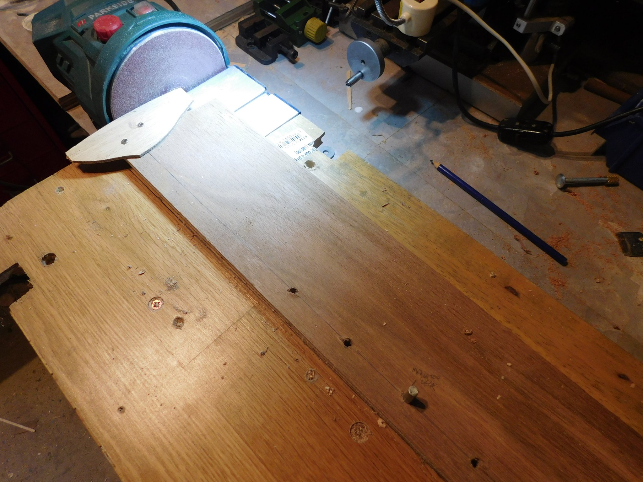
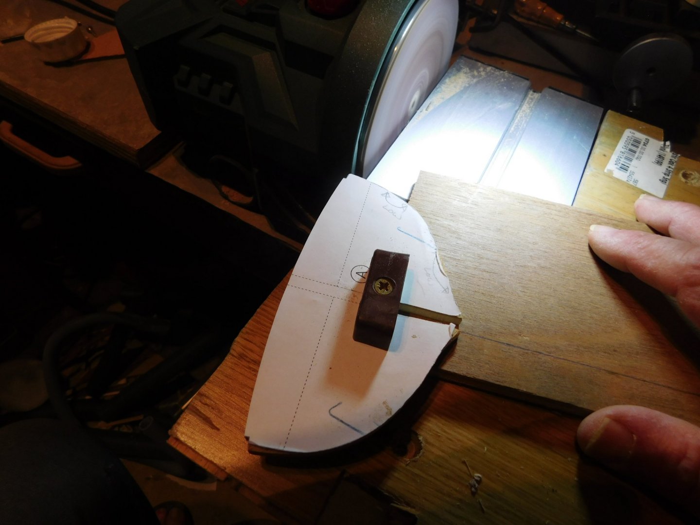
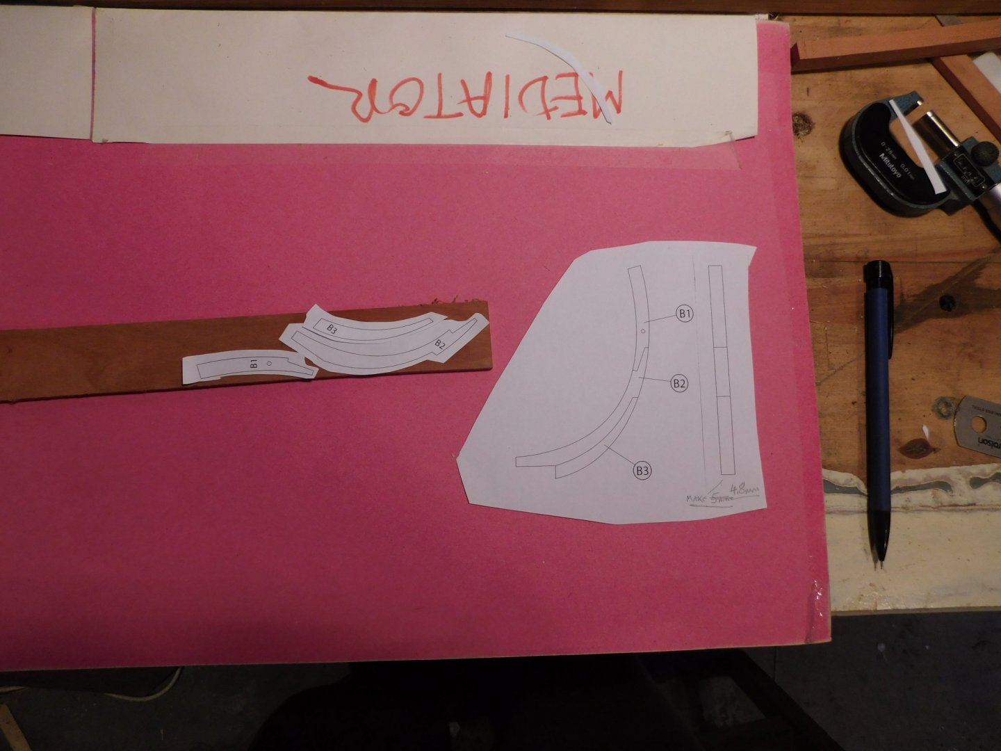
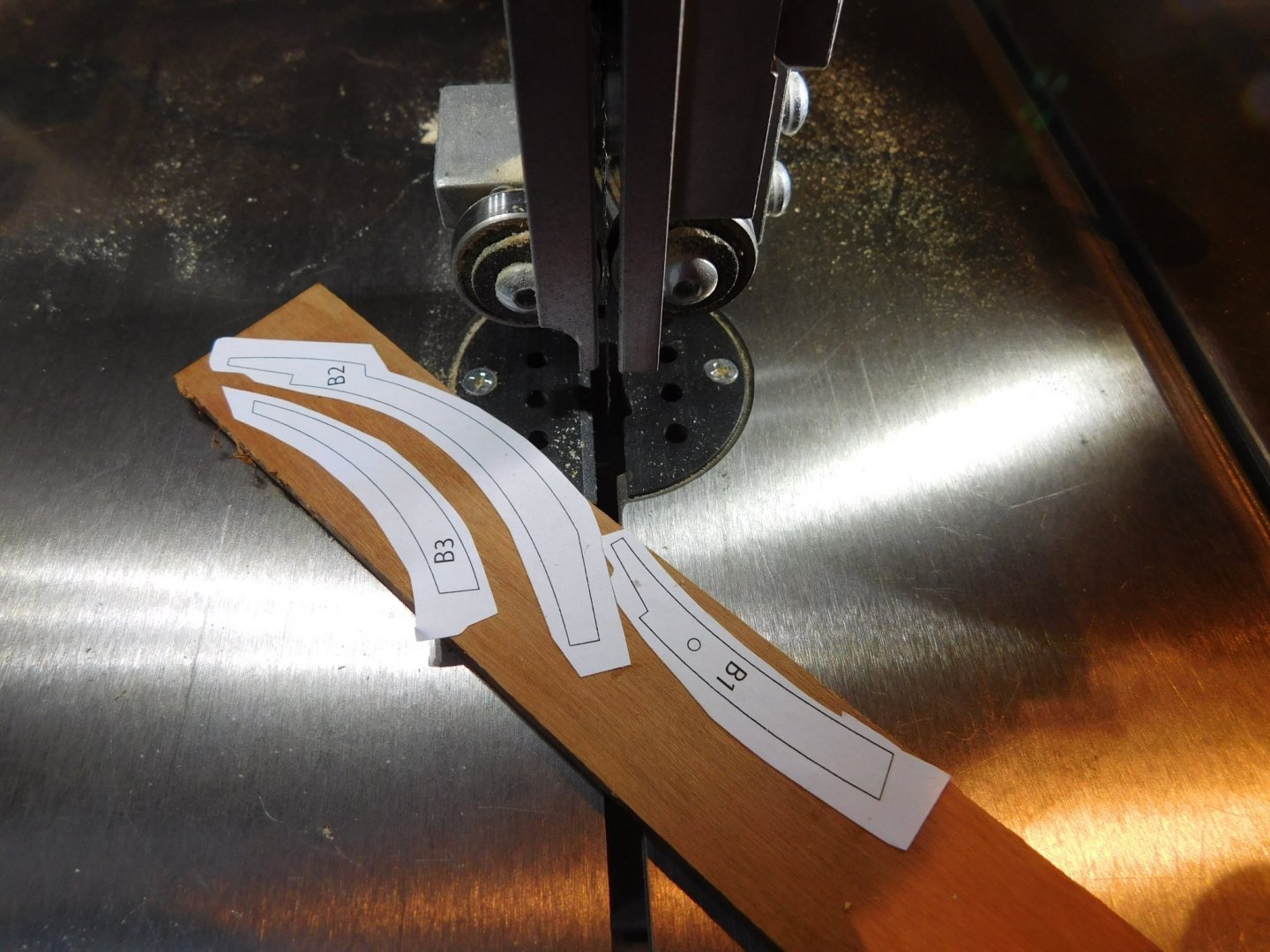
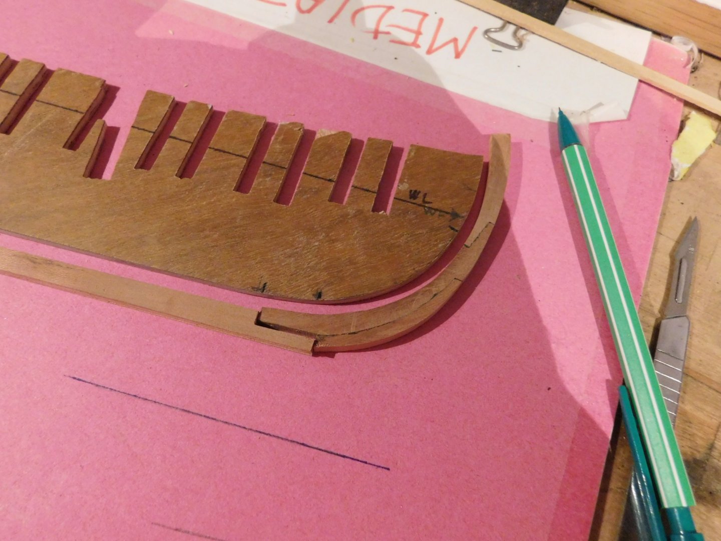
Been working on the bulkheads for Mediator. After getting the outside profile of all the bulkheads correct I turned to their tops, which support the decks. I really did not like the thought of truing up the lines of all 19 individually so I made a jig gizmo to semi-automate the process. I will post details soon in the 'tools' forum. The workpiece is fixed to the arm and then the whole assembly pivots on the pin (lower right). Bulkheads are held by an improvised screw-down clamp. Gives a good finish ... ... and consistent results. I should have the bulkheads assembled soon.


- 43 replies
-
- 7
-
-
- mediator
- first build
- (and 1 more)
-
New member from Scotland, very old krabbencutter
bruce d replied to Paul Carswell's topic in New member Introductions
A belated welcome to MSW. Like the crab boat. -
Welcome to MSW and I look forward to seeing your 'travels with my kit' build log. Just remember to put the tools in the hold luggage! Like you, I enjoy the archive digging as well as the time at the workbench. Bruce
-
Welcome to MSW, I am looking forward to a Chesapeake Bay craft.
-
A DIY thickness sander
bruce d replied to Kris Avonts's topic in Modeling tools and Workshop Equipment
Hello Kris, I look forward to seeing what happens next! Bruce -
new member from Hillsboro Oregon USA
bruce d replied to bruce1946's topic in New member Introductions
Hello Bruce, Well, you clearly can make a model. I would suggest you approach this by deciding which type of steam plant you want/can access and then the list of appropriate boats will snap into place. From experience: making a steam plant can be a massively time-consuming, and frustrating, project. A simple wobbler engine with a simple boiler is not as sexy as a Stuart D10 with lagged and plumbed scale marine boiler. If you want the '10', it may take a year to make the Bo Derek version but a couple of weekends to make the less exciting powerplant. Stuart Models can supply the steam packages in any form from unmachined kit to ready-to-run, including reversing gear, according to budget. I have no link with them other than being a satisfied customer. https://www.stuartmodels.com/ A long time ago plans for a simple "African Queen" were produced by a firm called HOBBYS here in the UK. I saw at least one project started using these blown up to a large scale (around three and a half feet in length) but sadly the builder was not able to complete it. It was scaled to match a Stuart Number 4 and was a good example of making the model match the most demanding component. Whatever you decide, please let us in on the build! Welcome to MSW. Bruce- 11 replies
-
- 1
-
-
- steam powered
- tugs
- (and 1 more)
-
They look superb. Now I'm looking around to see if there is a local version of your hippie-dude.
-
Hello Gerry, You are not the first to scratch your head over this but in fact it is easy when you know the trick. Upload your photos. They will be in a box at the bottom of the page you are writing. Enter your text and then place the cursor where you want the first picture. Godown to the uploaded pics and click on the '+' button within the image you want to insert: it will appear where you left the cursor. Repeat for each image. I find it looks better if you put a couple of lines of space below your text when placing the cursor but try it and see what suits you. HTH Bruce
-
Mini Lathe recommendations?
bruce d replied to jfinan's topic in Modeling tools and Workshop Equipment
I can't explain why there is a difference, but there are Unimat collet chucks frequently sold on Ebay UK for a lot less than that. There is one at the moment for an SL at £155. The aftermarket items usually take ER16 collets, the originals take E16. You can use ER16s in a chuck made for E16s but not the other way around. E16s are no longer in production so only ER16s matter. There is at least one UK seller who makes ER16 collet chucks with the Unimat M12 x 1 thread, usually around £140. Let me know if you want to follow up on this, P&P to the USA shouldn't be bad. HTH Bruce -
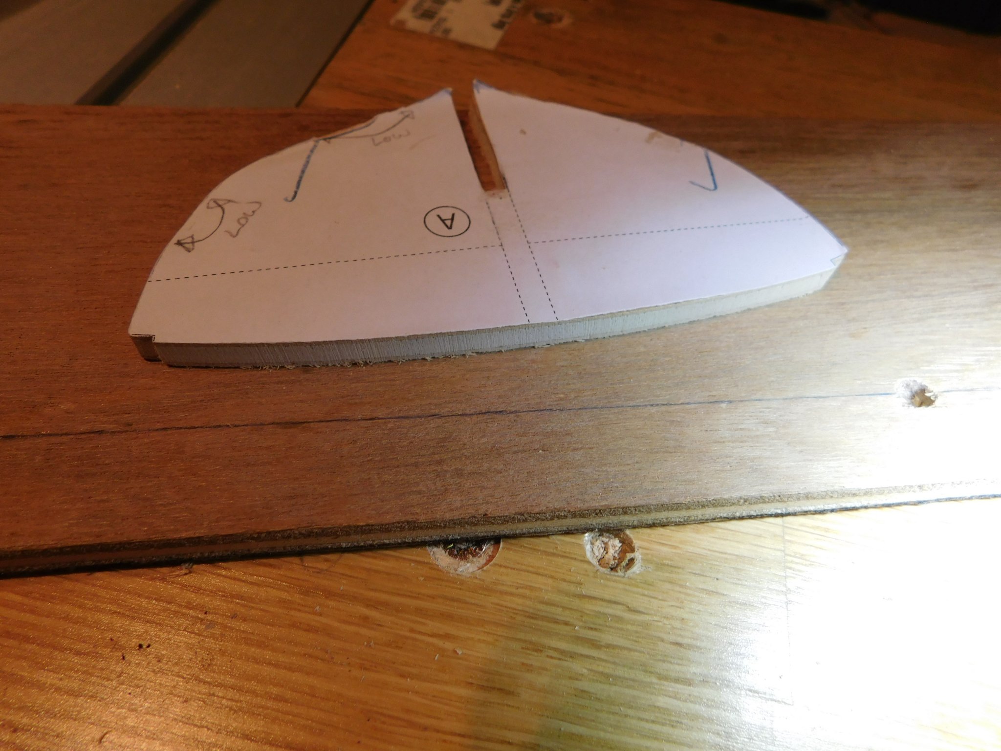
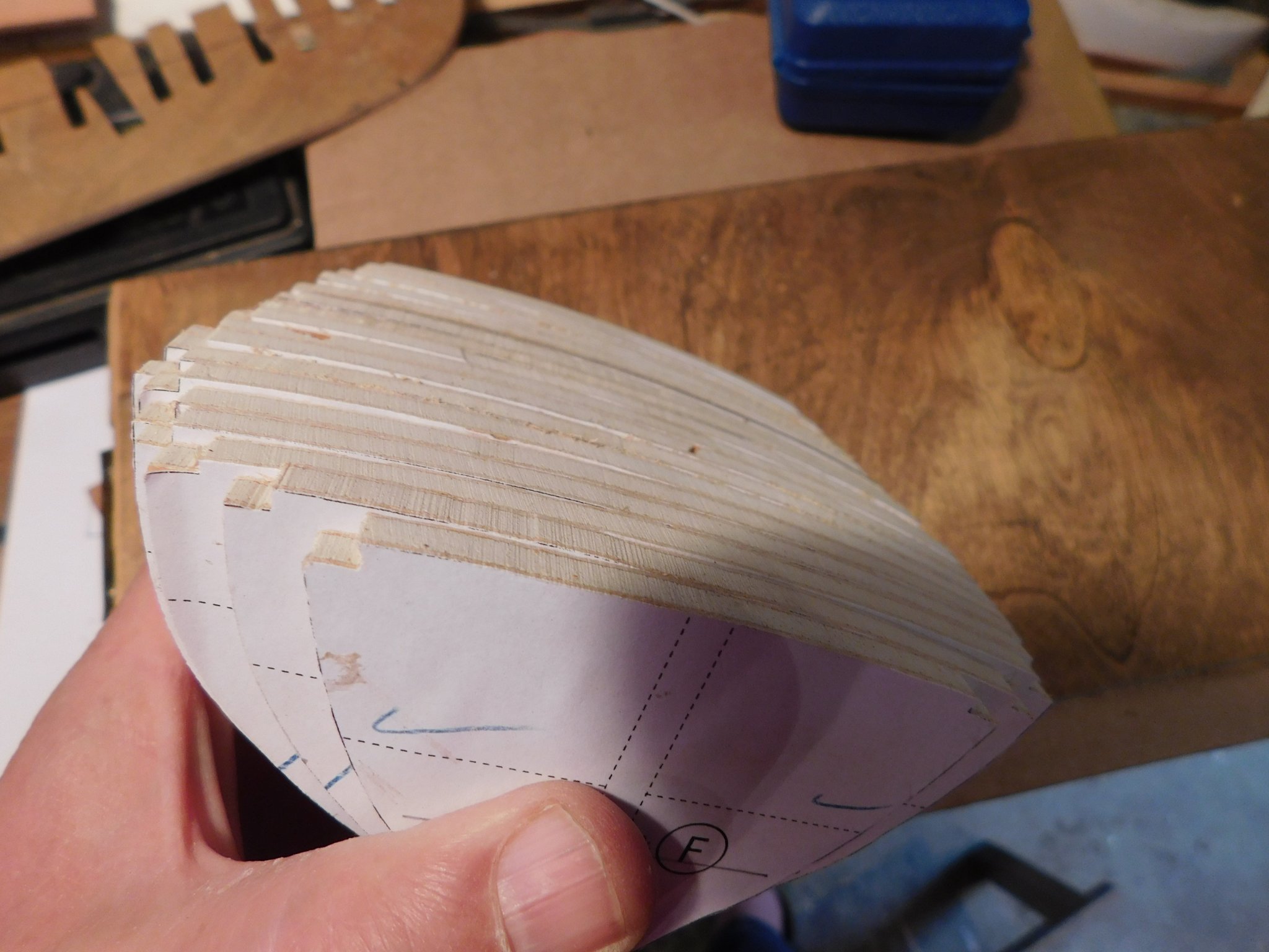
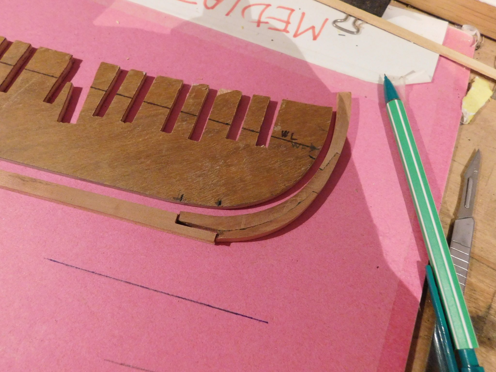
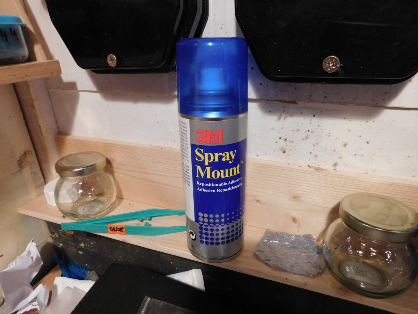
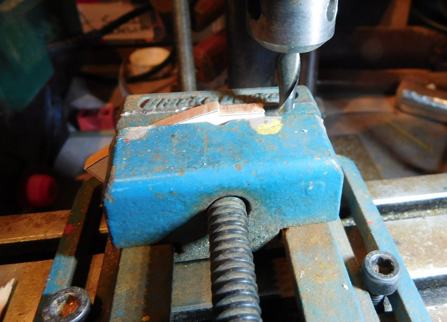
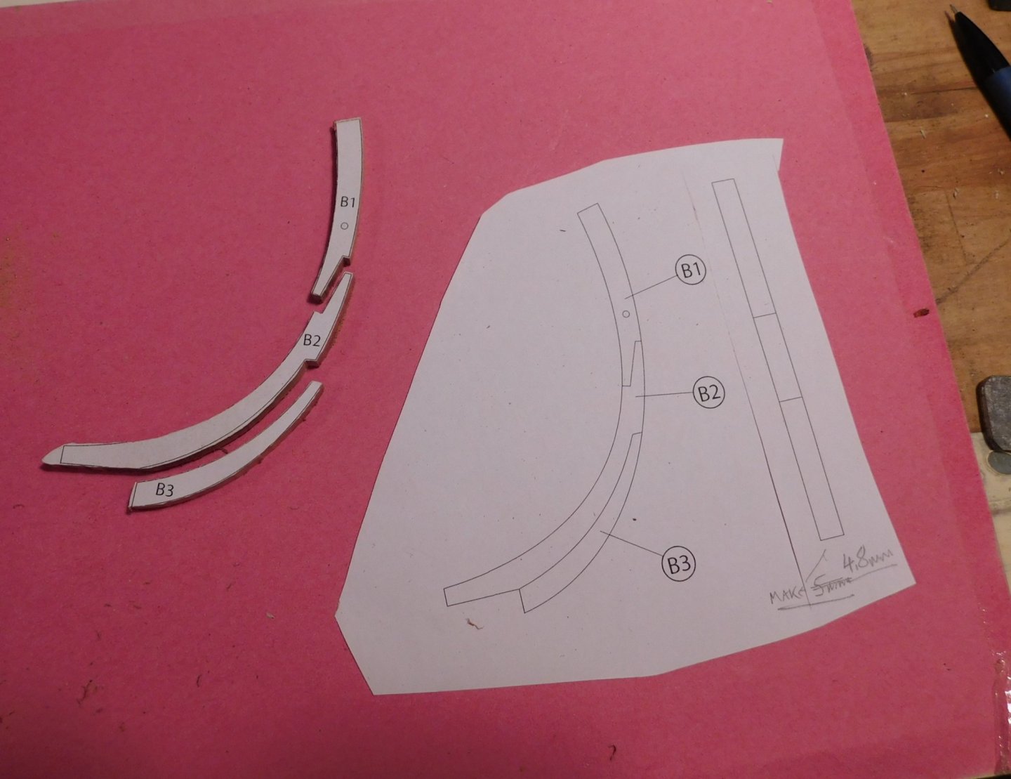
After agonising over the rights and wrongs of the two options, I decided to attach the keel, stem and sternpost after installing the bulkheads. It may be obvious to others but it certainly made me think about how scratchbuilding is deep water. Next up is the stem. The wood in this group is cherry except the false keel and all shaping and fitting had to be done while it was still possible to lay the hull former flat on it’s side. The plans were stuck to the cherry in line with the grain. The earlier experience with an over aggressive spray adhesive is history: this is my new go-to spray adhesive and it works like a charm. It is strong but in one of those mysterious ways that only chemists can explain it is also temporary. For about 24 hours after initial application you can peel away the paper and clean away the residue with a touch of IPA. Once the pieces for the stem were cut out on the bandsaw and tidied a bit, the scarf joints were milled. This worked smoothly but I realised I should have left more waste area around each of the pieces when I cut them out as there was no ‘second chance’ should I have wanted to re-do a cut by even a tiny amount. No problem, but noted for next time. I did not attach the pieces to each other until the individual pieces sat properly in their position against the former. I marked the former where the scarf between the stem and keel should be (the transition from curved stem to straight keel) and worked from that. This allowed me to offer up the lower of the stem pieces and make a mark where the upper scarf would fall and everything else followed from that. Fitting and fettling of the first two pieces done, I glued them together and started to repeat the process for the final bit of stem. This was mostly just a process of offering up and making a lot of small tweaks. It was important to get the curve right on the front edge: the line of the curve will be continued as a straight line giving a taper in elevation to the false keel. Easily done by using a copy of the drawing as work board. The stern post is also ready and I will trim it to join the keel when they are all fitted to the former. Now I can move on to the bulkheads.
- 43 replies
-
- 7
-
-
- mediator
- first build
- (and 1 more)
-
Mini Lathe recommendations?
bruce d replied to jfinan's topic in Modeling tools and Workshop Equipment
Odds are good that the right hand chuck has a set of Unimat soft jaws. Can't say for certain as there were also some very good aftermarket chucks that (I believe) came with jaws of that shape, possibly the Indian 'Soba' brand. Free advice, treat it as such: If you have recently acquired these and don't know their history, I suggest a total strip down (three minutes work), de-grease and a tiny touch of copper-grease before reassembly (another three minutes). The original Unimat chucks were great but many have been in the hands of well meaning users who (a) overtighten them and (b) bung any old grease or oil into their cavaties. I like the saw table. -
I'll say it did. I like what you have done with the laminate. As I am about to make a smaller version out of some veneers laying around it was interesting to come across your description. I've heard people say 'We're going to need a bigger boat'. Well, looks like it's on the way.