tlevine
-
Posts
2,022 -
Joined
-
Last visited
Content Type
Profiles
Forums
Gallery
Events
Everything posted by tlevine
-
 Funny you should say that, Druxey. I started howling yesterday when I opened a cabinet that I had not been in for a while. My husband thought I injured myself but the pathetic truth is that I had just discovered a half-full bottle of isopropanol that I had forgotten about!
 -
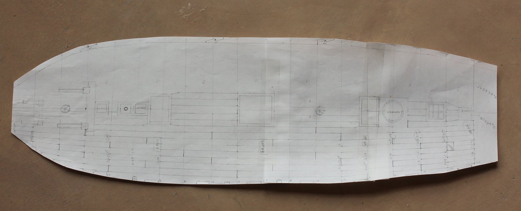
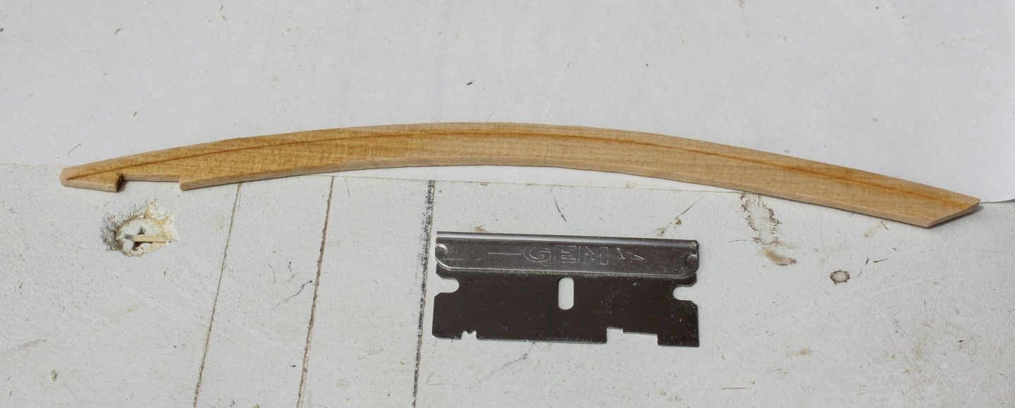
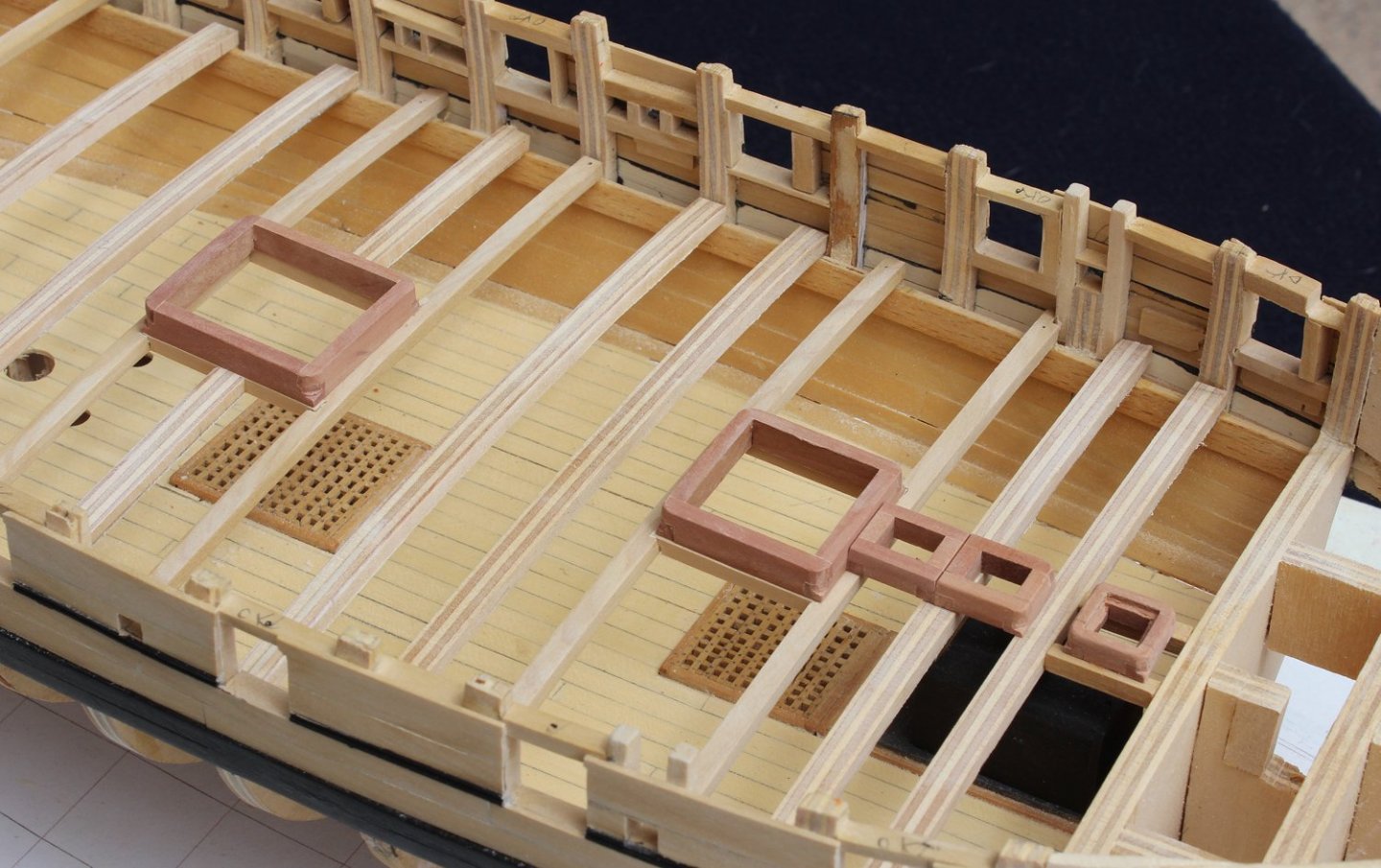
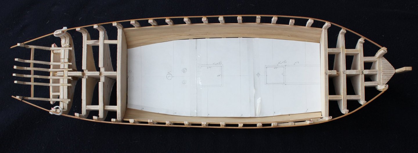
I made of template of the upper deck and drew in the deck openings, furniture, planking and waterway. Although this took a few hours to complete, it will save a lot of time over the next few weeks. On the starboard side one can see the four waterway planks. The deck planks and the locations of the ports are seen on the starboard side. I decided to taper the planks from the bow to the fore hatch and aft of the main mast. Templates were made for the four sections of the waterway. Using the same razor blade that has the upper hull molding pattern, I cut out a pattern for the waterway. The waterway looks like a stair-step; the section that meets the deck planking is 3" thick and the section that meets the inner bulkheads is 4" thick. The waterway is made from castello. The pictures show the foremost sections of the waterway laid onto the deck beams. Only six more sections to go!
- 277 replies
-
- 23
-

-
Well, Druxey, I obviously forgot about applying the molding over the planking. Next time... Actually, this mistake worked out well since I did not have to worry about glue seeping out from underneath the molding. I am trying to stretch my precious half bottle of isopropanol.
-
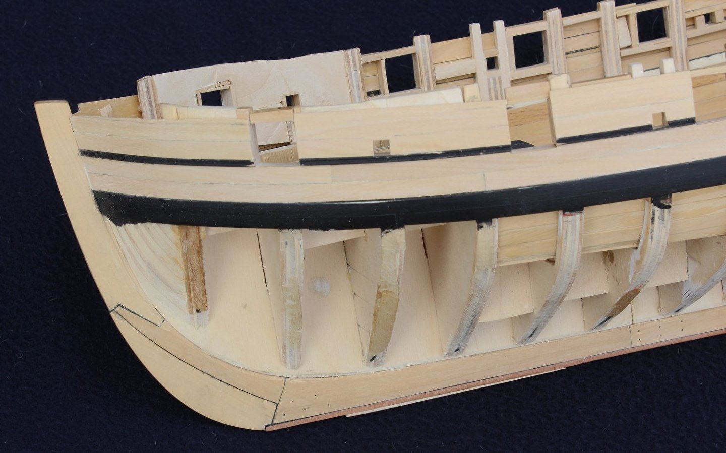
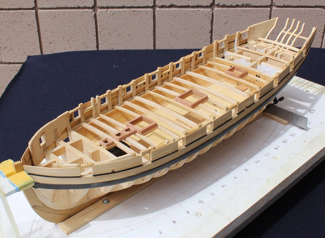
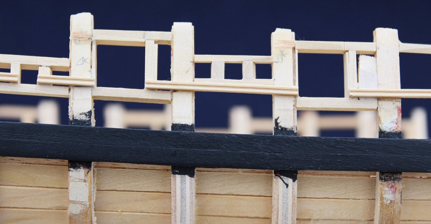
The next step was to plank the upper hull with costello boxwood. This was straight forward and required minimal tapering of planks. At this point I made my final decision regarding the frieze above the gun ports. I decided to model the plan and not the model. The rail will form the top of the gunports but I have not trimmed the excess bulkhead material yet to prevent damage to the planking. After finish sanding the planking, the paint on the wale was touched up. There is still a little more to do but this will wait until after the lower hull is planked. As you can see in the pictures above, the deck beams are now installed. They are a combination of plywood where they will not be seen and boxwood where they support the hatch and ladderway coamings. Carlings were placed between the beams that support the hatches. The stove has been temporarily removed. All of the coamings are made of swiss pear. The large coamings are 4 1/2" wide at the beam and taper to 4" at the top. They are 13" tall. The curve of the deck was sanded into top and bottom of the athwartship faces of the coamings. The small coamings for the stove chimney, steam pipe and light are 3 1/2" wide and 8" tall. The capstan base abuts the ladderway. It is parallel to the waterline. The difference in angle can be seen in the next picture. A skylight will be located behind the capstan. I painted the bulkhead and spine black where it will be installed.


- 277 replies
-
- 17
-
-
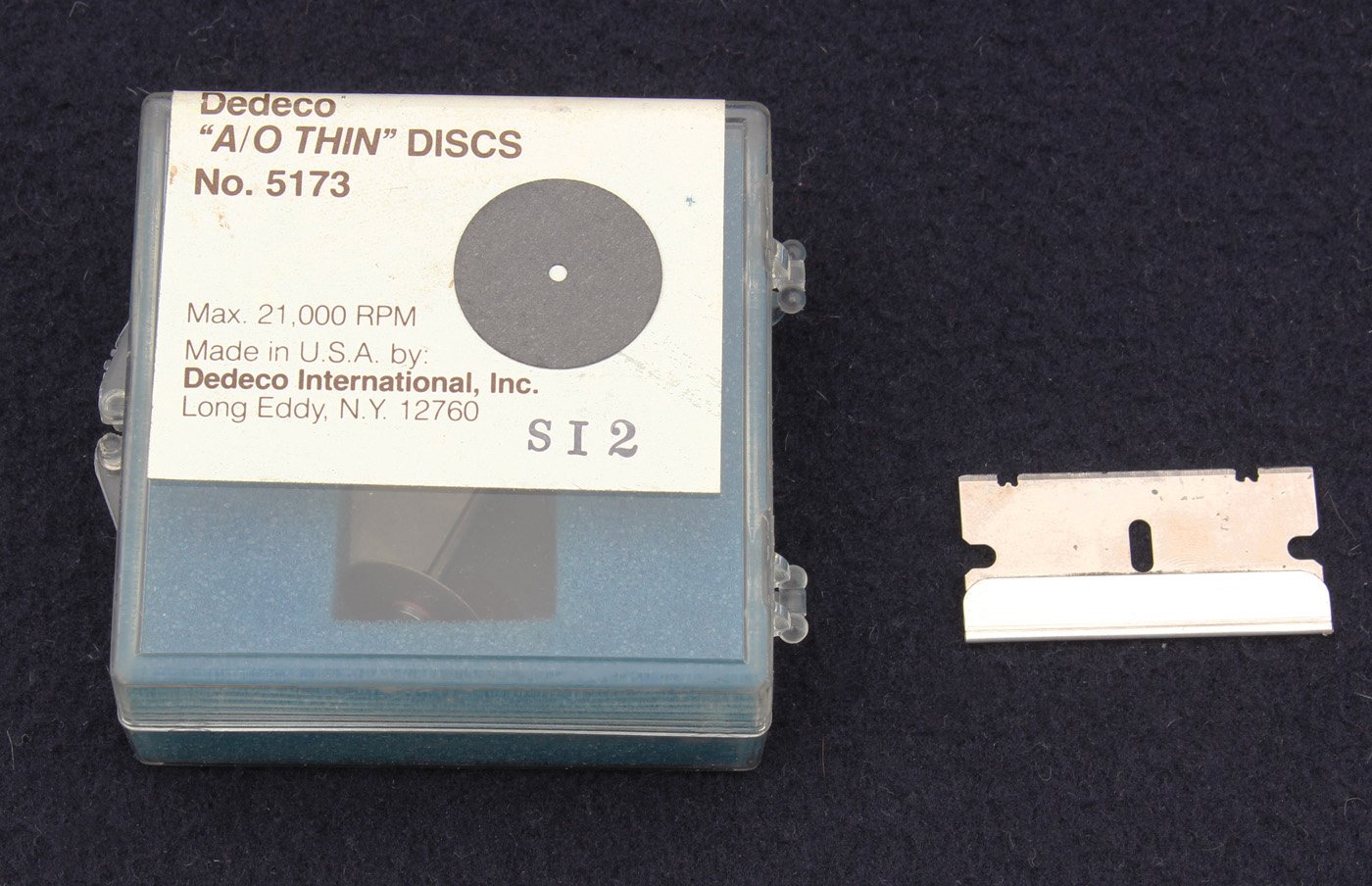
I cannot believe it has been almost six weeks since my last posting. Quite a bit of progress has been made on Swallow; some of it is even visible. Throughout the planning and start of the build I have had a difficult time reconciling the model and the plans. For example, the model has a beautiful frieze between the top of the gunports and the rail. At this point I was still deciding which direction to go...model the plans, model the model or do something in between. The next step is to install the wale. This was made from two thin layers of holly to make it easier to bend the wood at the bow. I ran two strips of chart tape along the hull and marked between them with black marker. This made it easier for me to develop a smooth run of planking. The first layer was installed with two rows of three planks each. This was tapered down at the bow as the final thickness of the wale is the same as the thickness of the rest of the hull planking at the rabbet. The second layer was then installed, laying the plank butts on different bulkheads than the first layer. There is a decorative strip above the wale. On the model this is located halfway up the gun ports but on the plan it is at the base of the port but cuts through the oar ports. I make my moldings using "A/O Thin" discs that I chuck onto the Dremel. These are much thinner than the discs sold by Dremel. A single edged razor works well but is more fragile than cutting the pattern into a thicker sheet of metal. I will usually put four different patterns on each razor blade. The pattern on the right was a little too deep and not perfectly symmetric so I am using the pattern on the left.


- 277 replies
-
- 10
-
-
HMS FLY by cafmodel - 1/48
tlevine replied to cafmodel's topic in - Build logs for subjects built 1751 - 1800
Very nice! -
Thanks for looking in. I have never been completely happy with the display base but I am more concerned about damaging the ship if I change things.
-
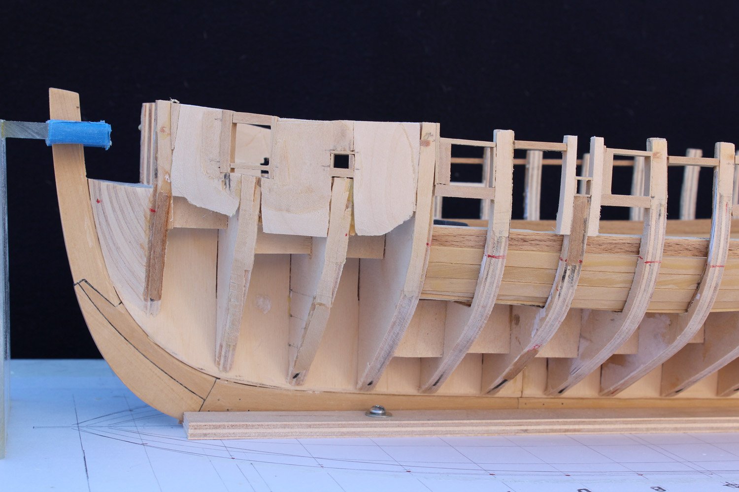
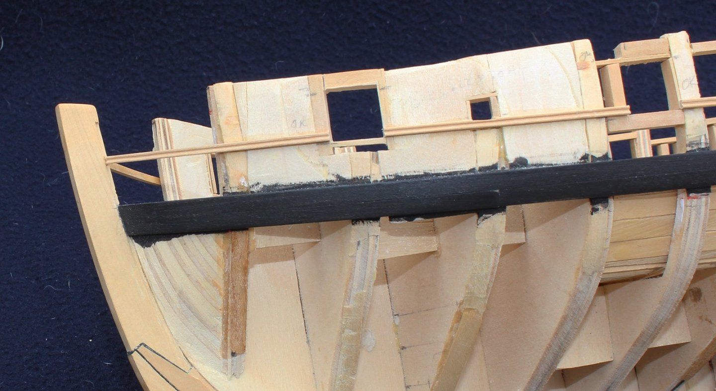
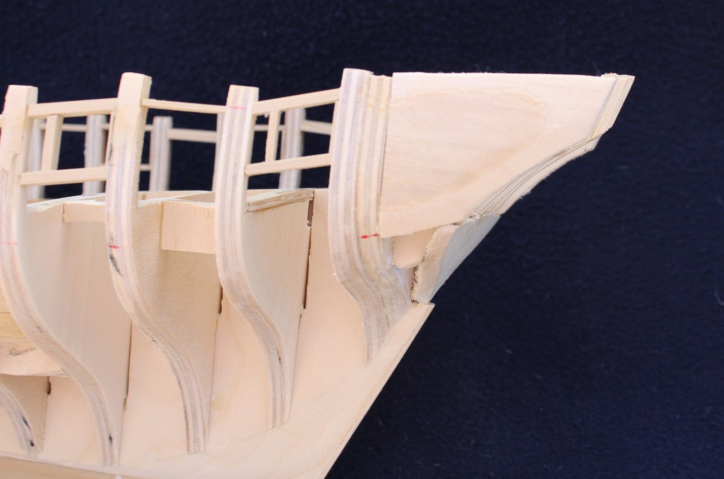
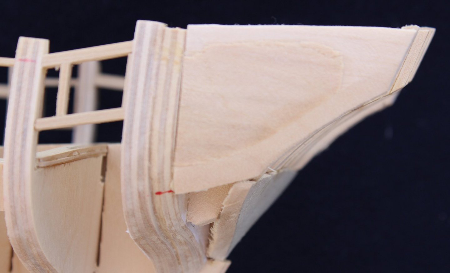
The inner upper deck bulwarks were faired to a thickness of 7" using a combination of a Dremel disc sander on a right angle head and hand sanding. The stern fashion pieces were built next. Quite simply, I used several laminations of basswood sheet to fill in the space between the last bulkhead and the counter timbers. These was sanded to the correct configuration. Using basswood made the sanding process much easier than if I had used hardwood or ply. Openings for the gun ports and the oar ports were framed with castello. The forward-most gun and oar ports are located in line with two bulkheads. This required some creative construction. My approach to the problem was to make a continuous filler piece between the first four bulkheads that could be slid in and out to facilitate shaping the inner surface. This was done using several scraps of basswood. It worked out well but it sure looks ugly! This will also give me a solid surface to glue the upper hull planking as it curves toward the stem rabbet. The next oar port also is located through a bulkhead. I glued strips of basswood on either side of the bulkhead and framed the port between them. The rest of the ports were located between bulkheads and did not cause any other problems. In order to maximize my use of the scrap box, the frames were cut from various thicknesses of castello. Once planked over, this variation will not matter.
- 277 replies
-
- 22
-
-
Echo by davec - FINISHED - cross-section
tlevine replied to davec's topic in - Build logs for subjects built 1751 - 1800
Lovely work. Count me in on the procrastinator's group. My Echo is still waiting for me to finish her. -
Thanks for the hint, Druxey. I realized the problem about 3/4 of the way after I had already redone it once. I promise it will not happen again! Also, thank you to everyone for their likes.
-
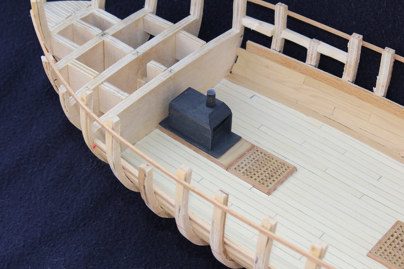
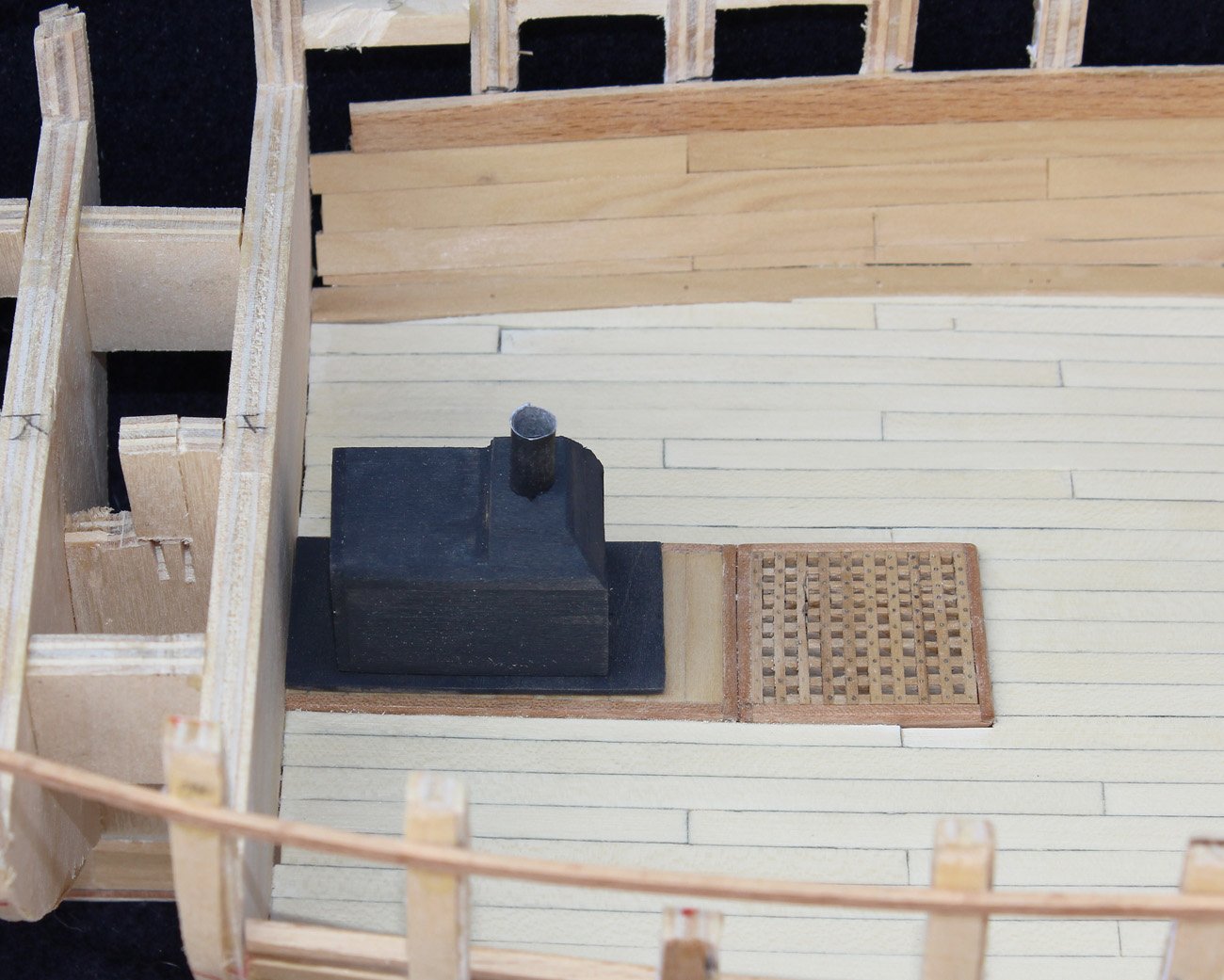
The ship's stove was modeled after the one illustrated in TFFM Vol. 2. Because this area will barely be visible, there is no detail work on the stove. It was made up from basswood sheet and painted with dilute artist acrylics. The metal base is painted paper.
- 277 replies
-
- 21
-
-
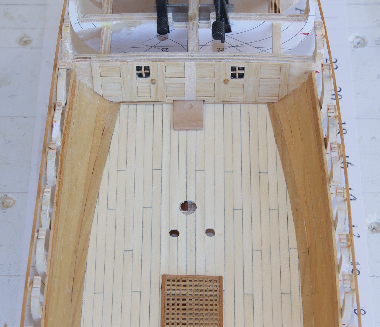
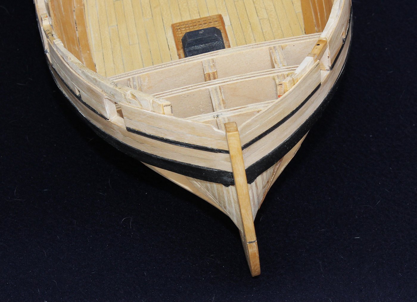
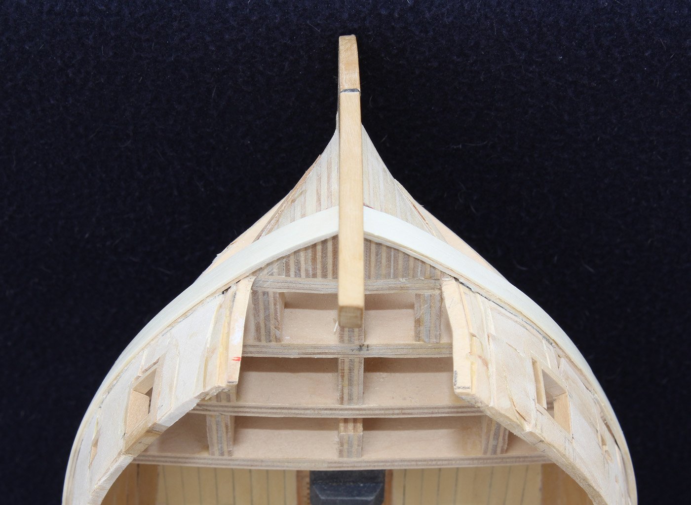
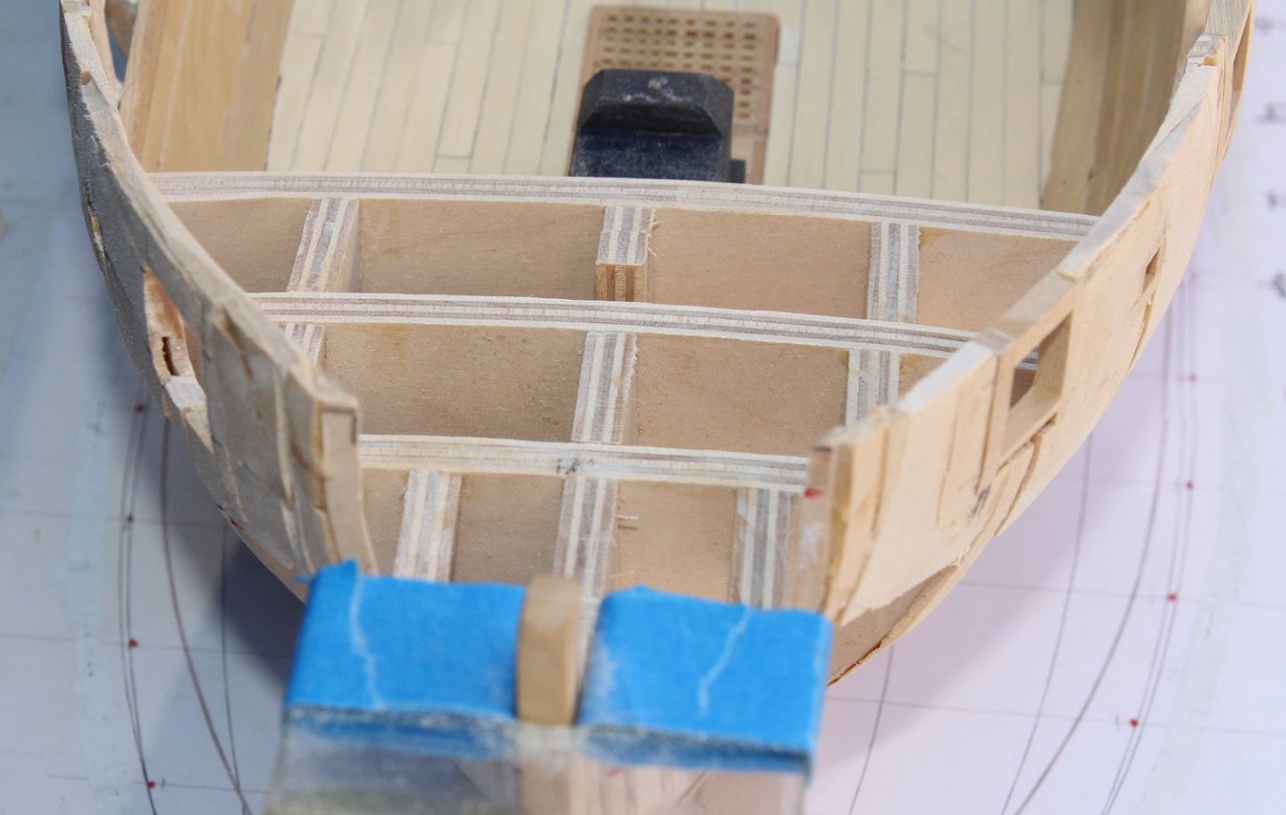
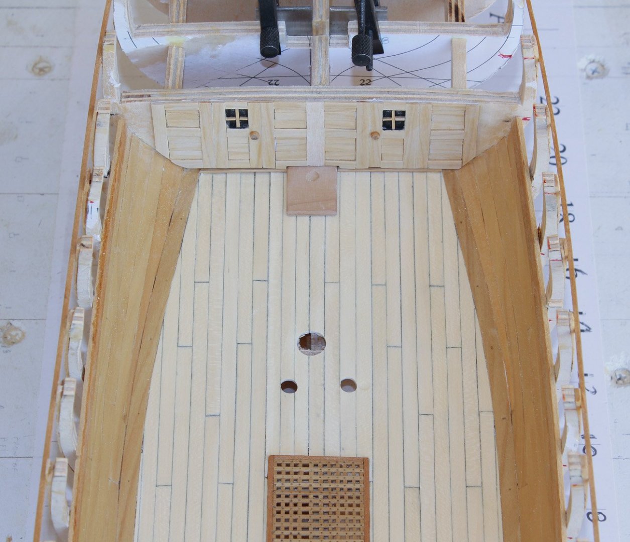
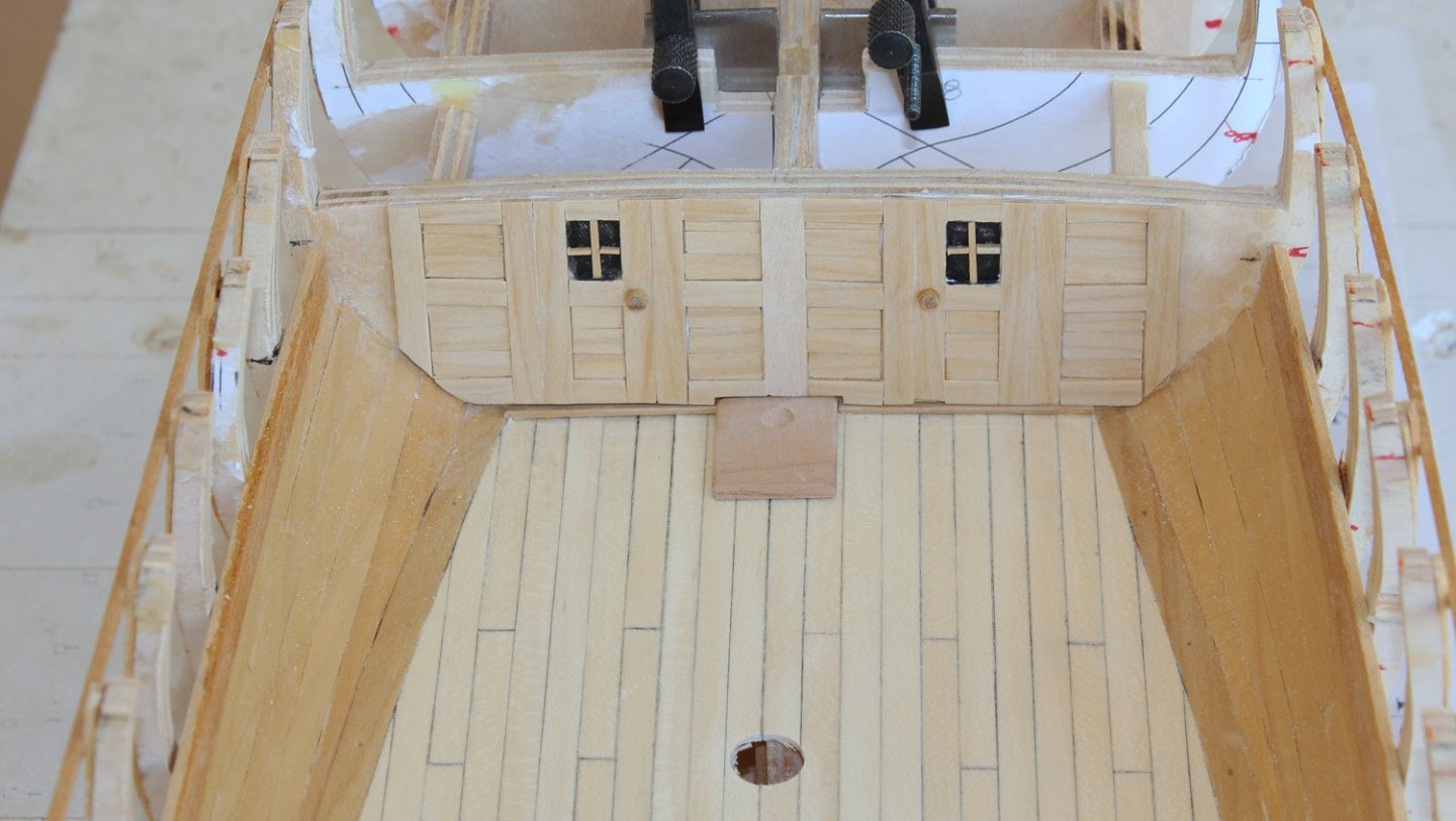
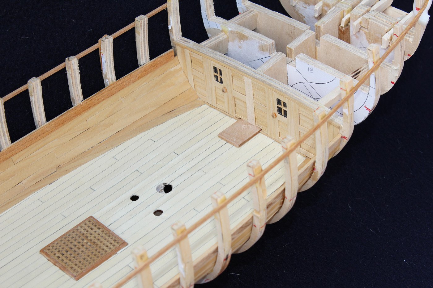
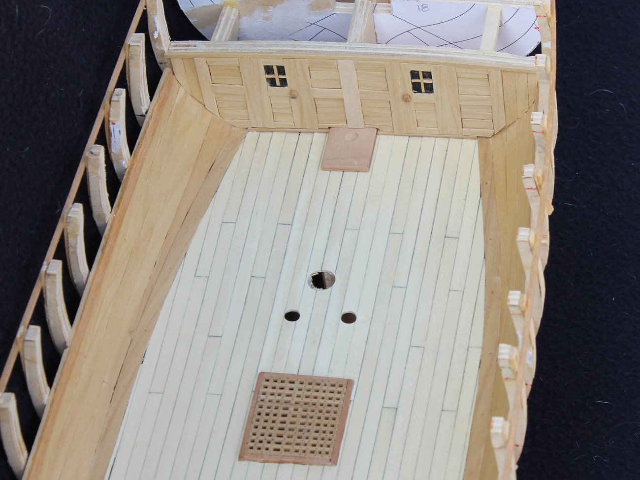
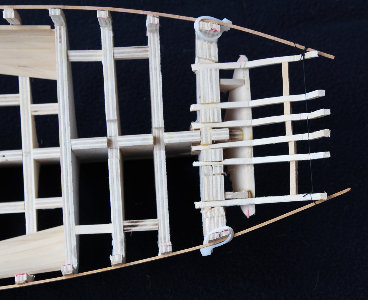
Until this point, I had not decided how much of the lower deck would be visible. My final decision is to have the fore hatch permanently fixed in place and the main hatch cover removed and placed to the side of the hatch. The stairway aft of the main mast will also provide visibility to the lower deck. For this reason, I am building the bulkhead just aft of the capstan spindle. This is the entry to the captain's cabin. The exact configuration is an educated conjecture. A template for the bulkhead was made from paper and the wood strips were glued onto the template. The raised areas are built up with two layers of strips. The windows are painted paper. After I installed the bulkhead, I realized that I did not leave enough room above the doors for them to open without hitting the upper deck beams. So I had to remove the completed bulkhead and remove 4" from the bottom to accommodate that. After reinstalling it, s finishing strip was glued above the assembly. The first two pictures are "before" and the last two are "after" replacing the assembly.
- 277 replies
-
- 21
-
-
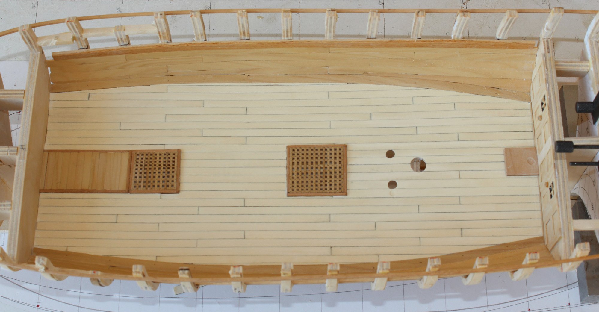
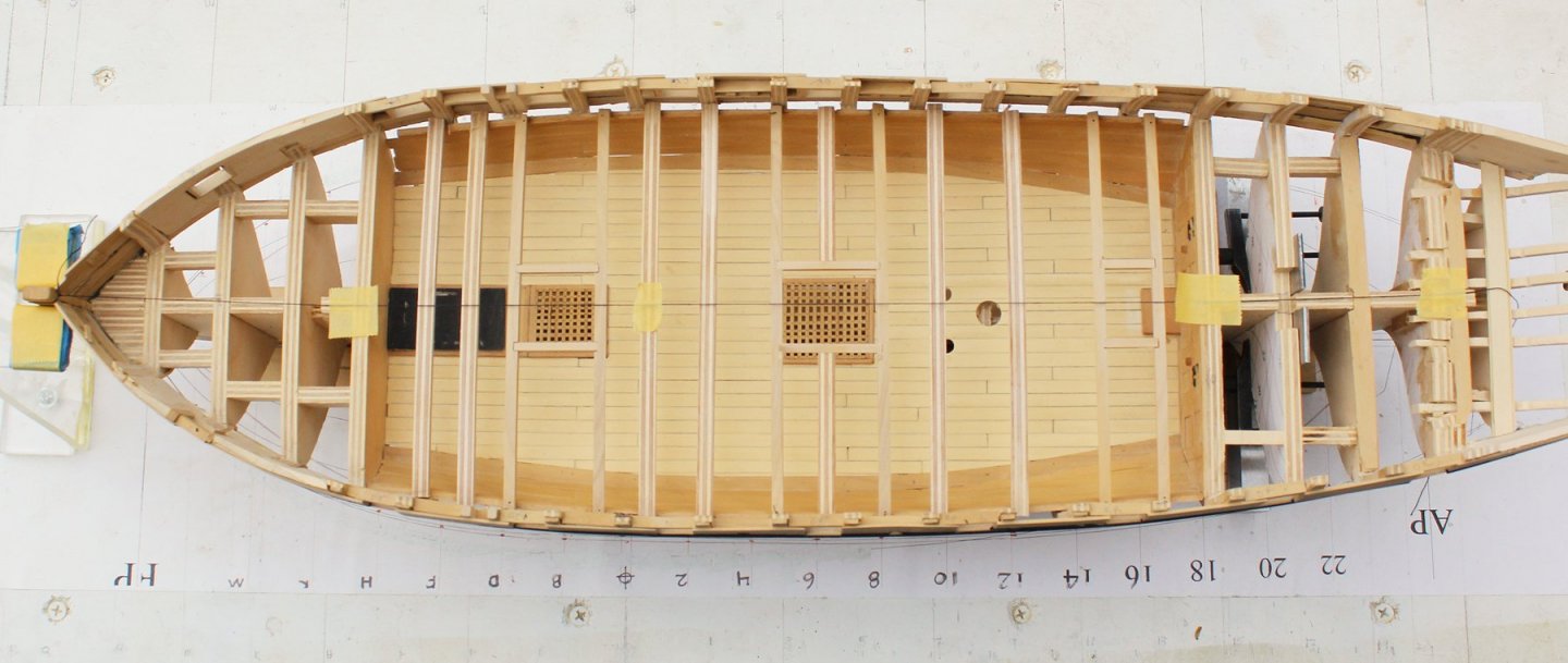
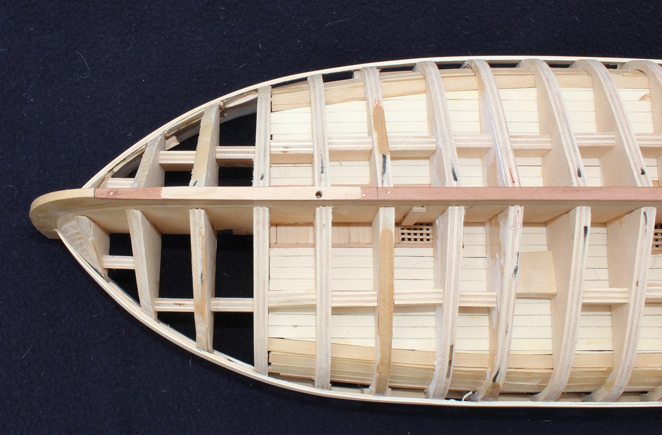
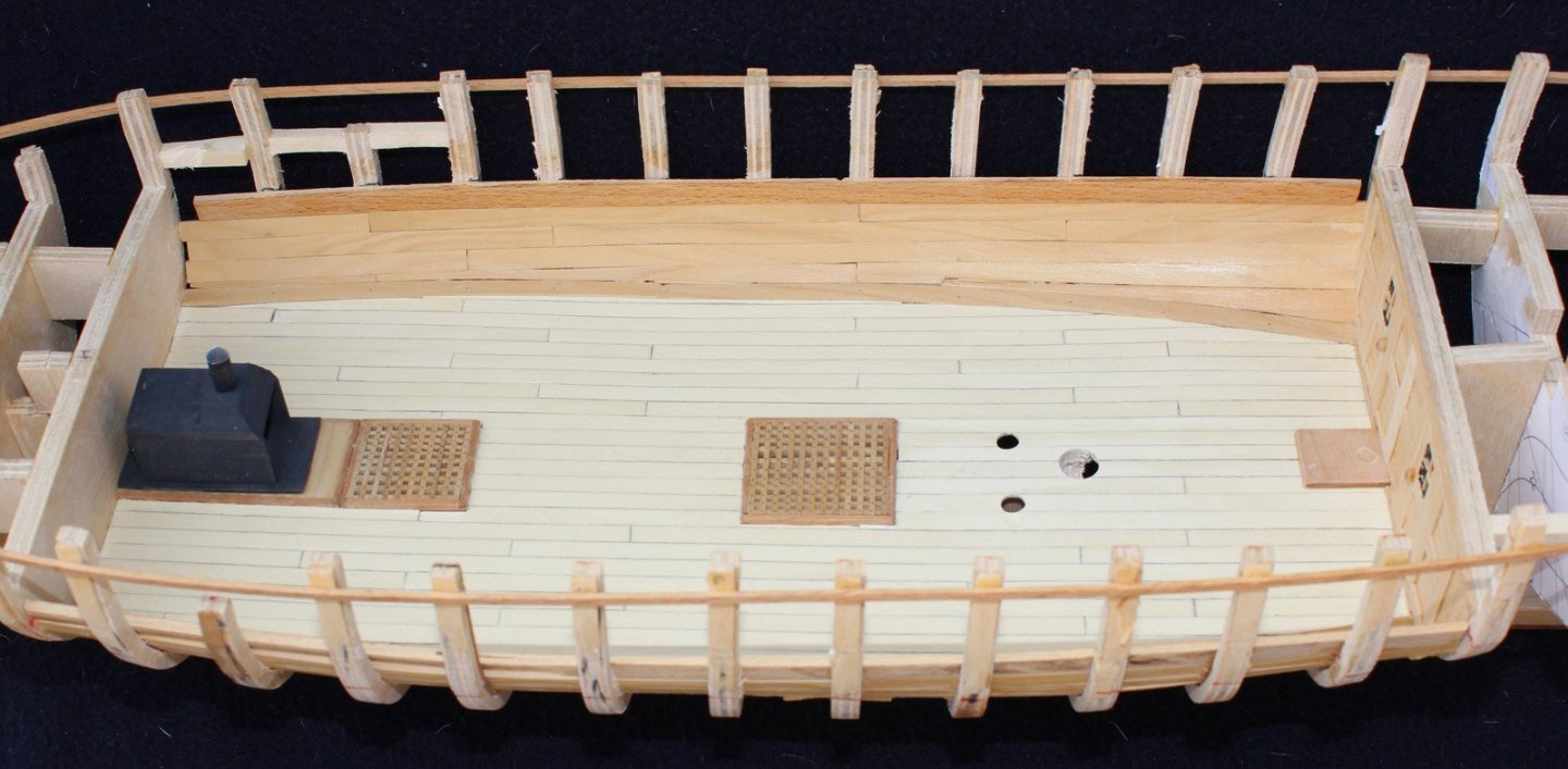
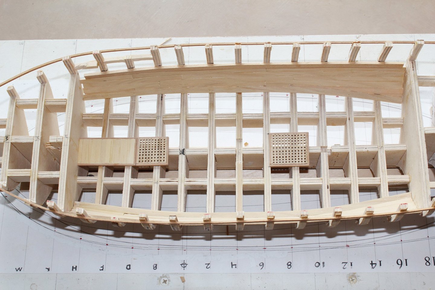
The lower deck planking is 2" x 10" with an average length of 15 feet. I used a four-step butt shift. As this deck will barely be seen, I did not treenail the deck. At this point I had an oh-s*** moment. I inadvertently placed the main hatch too far aft, a distance of one bulkhead. So all of the involved planking and the main hatch were removed. Surprisingly, I did not damage the hatch in the process. The hatch was then installed in its correct location. The hole is the location of the main mast. The holes for the mast and the pumps have been enlarged to their final size and the pad for the base of the capstan is installed in front of the bulkhead leading to the captain's quarters.


- 277 replies
-
- 21
-
-
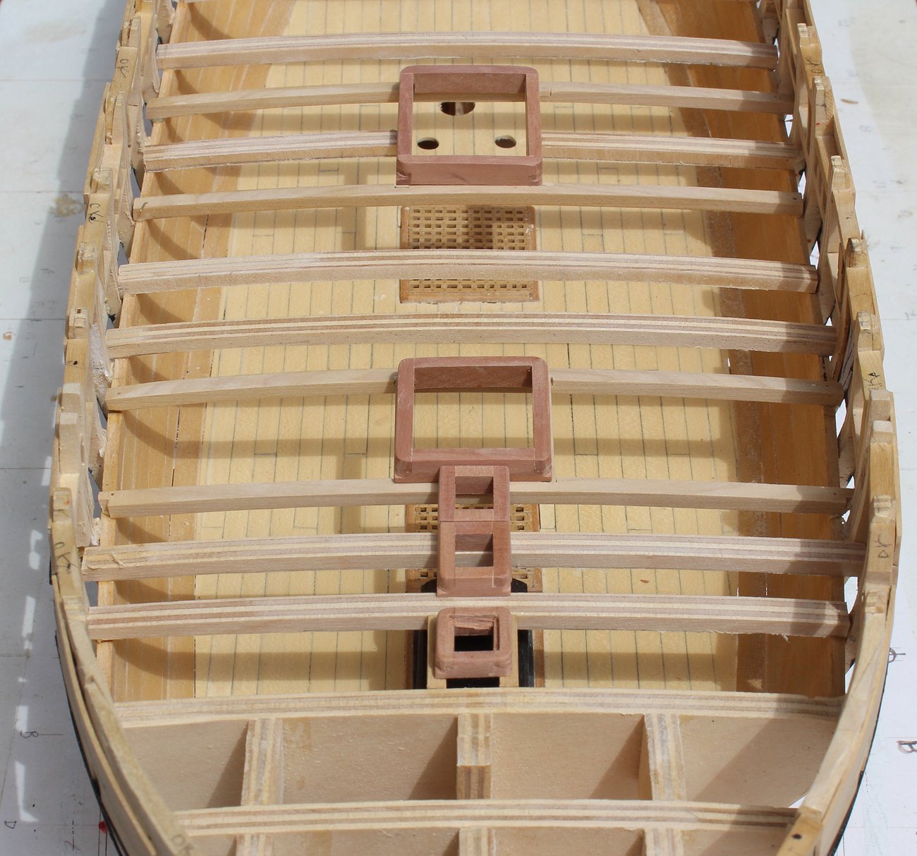
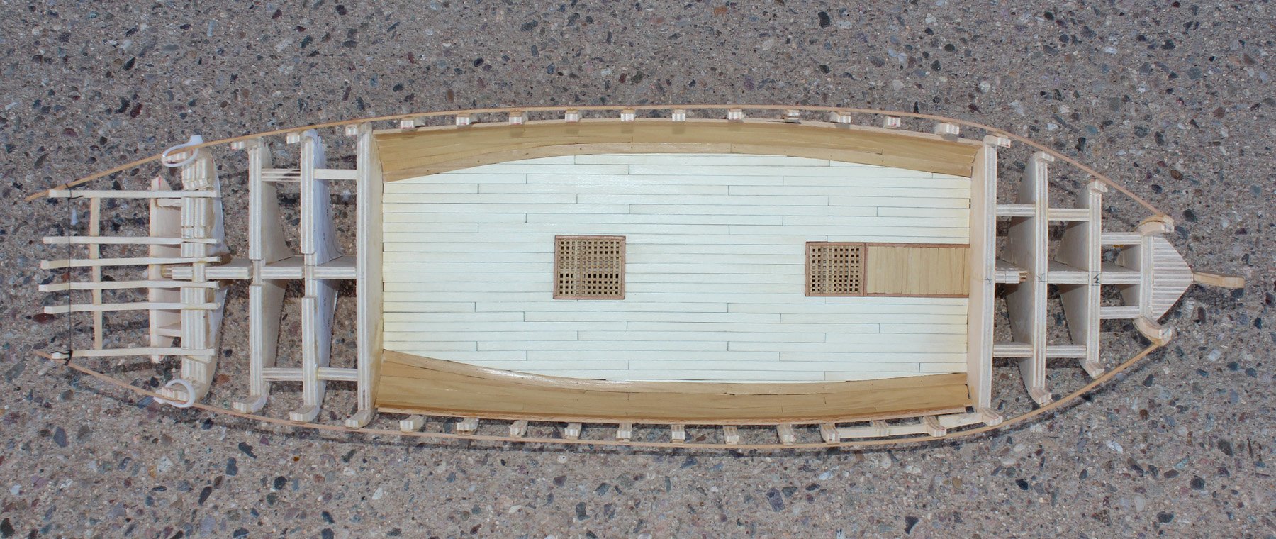
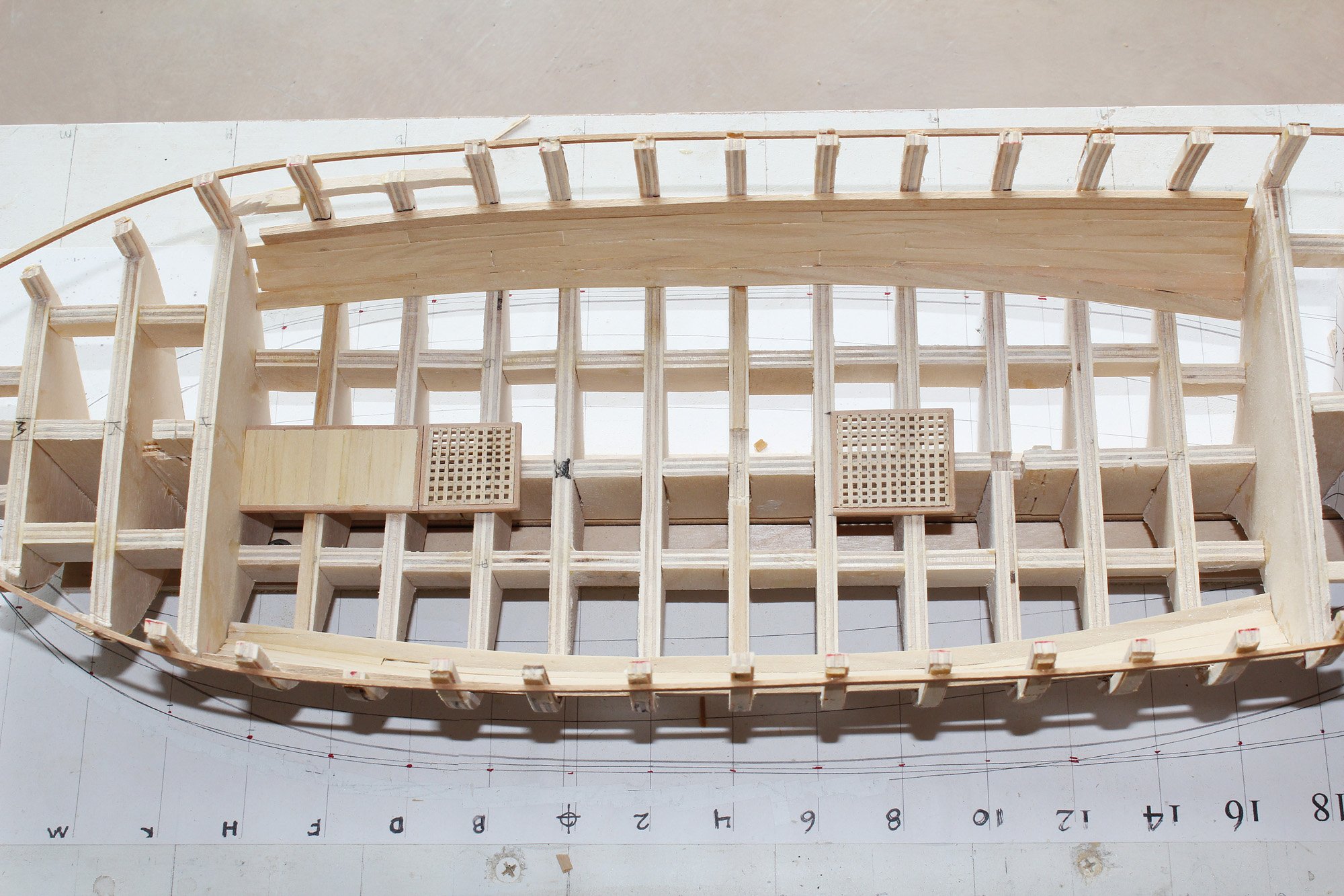
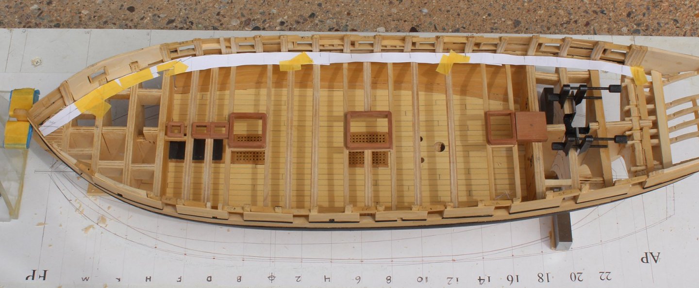
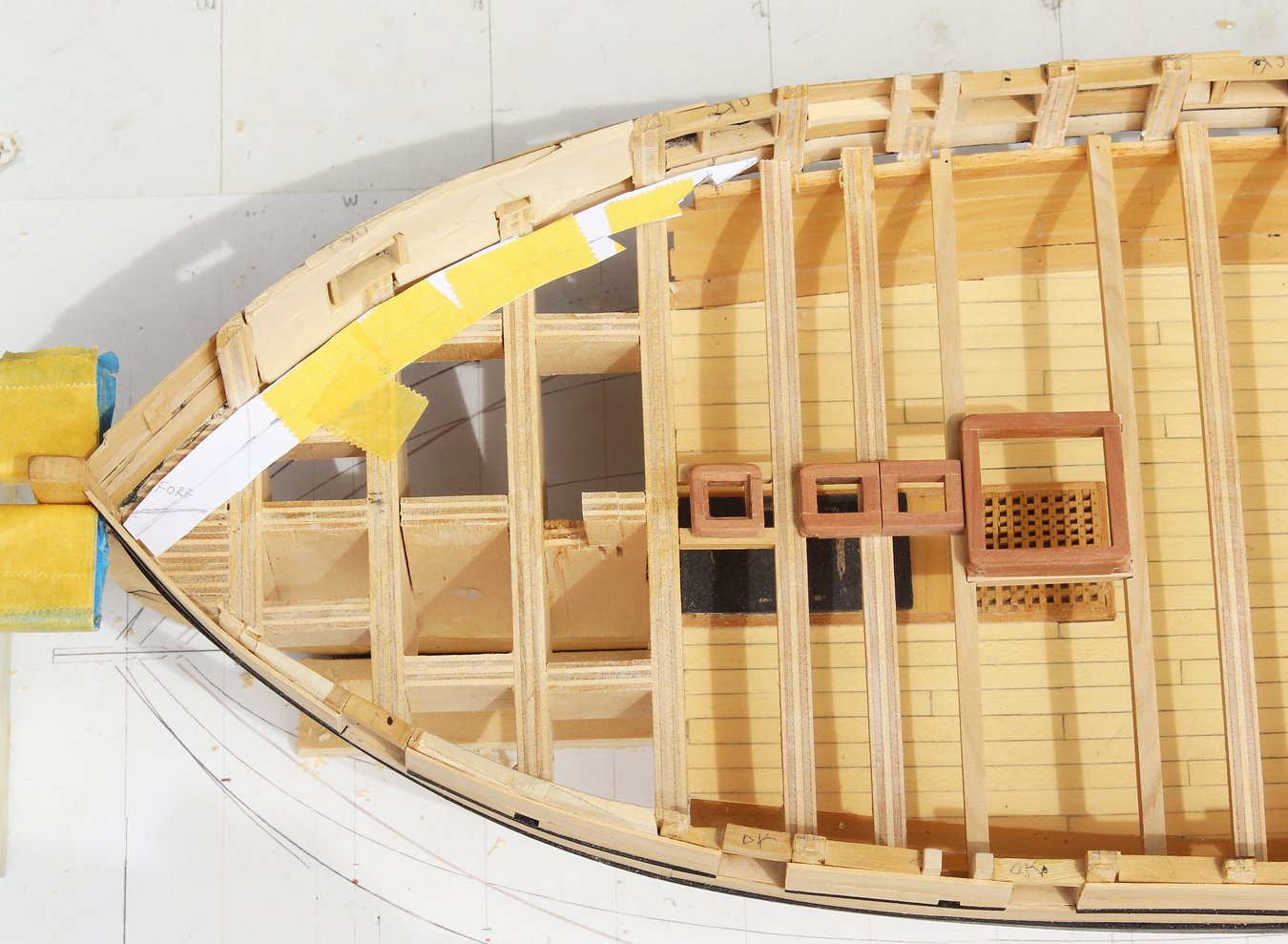
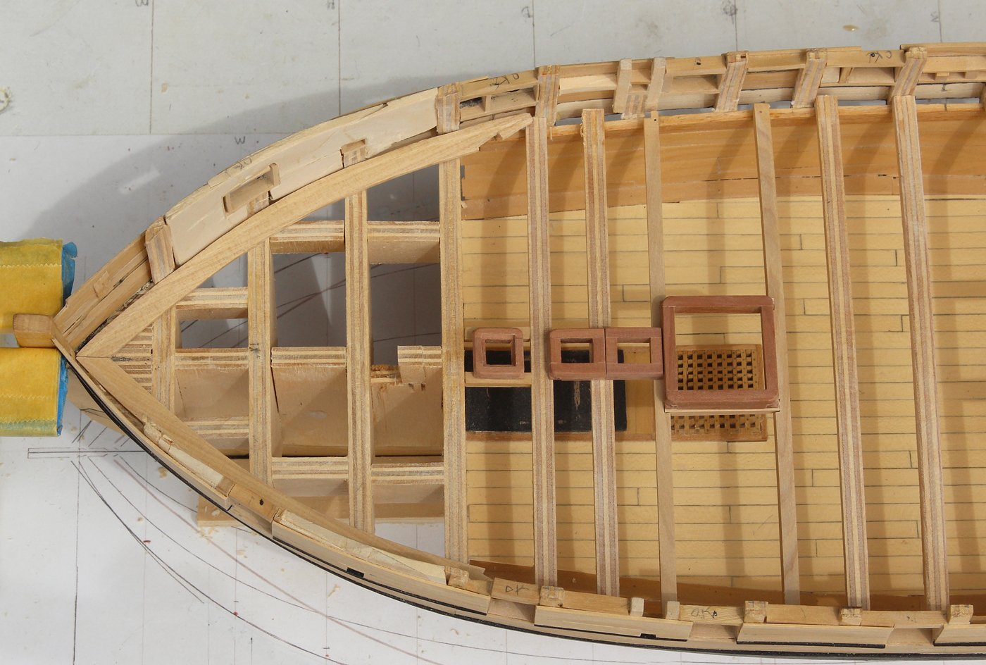
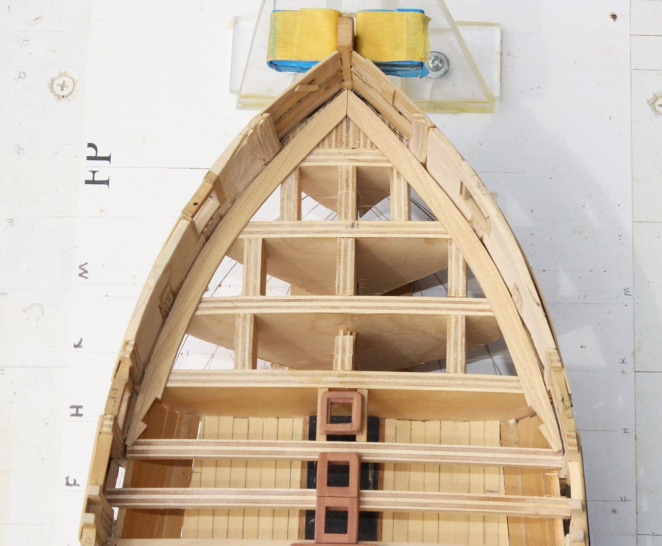
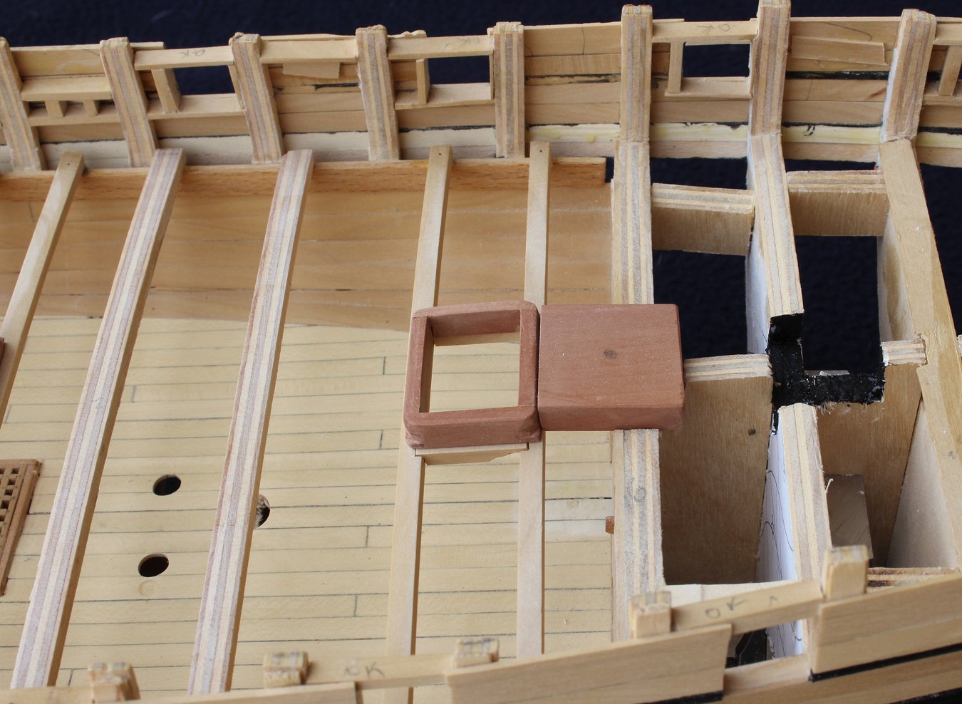
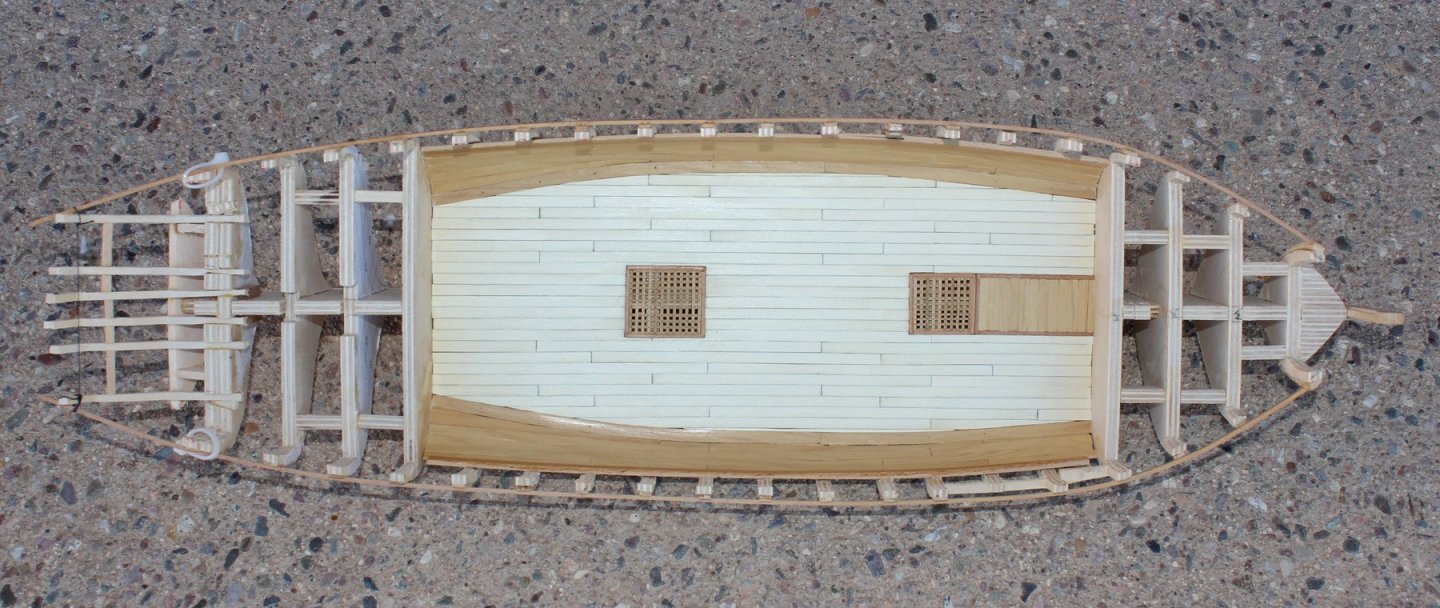
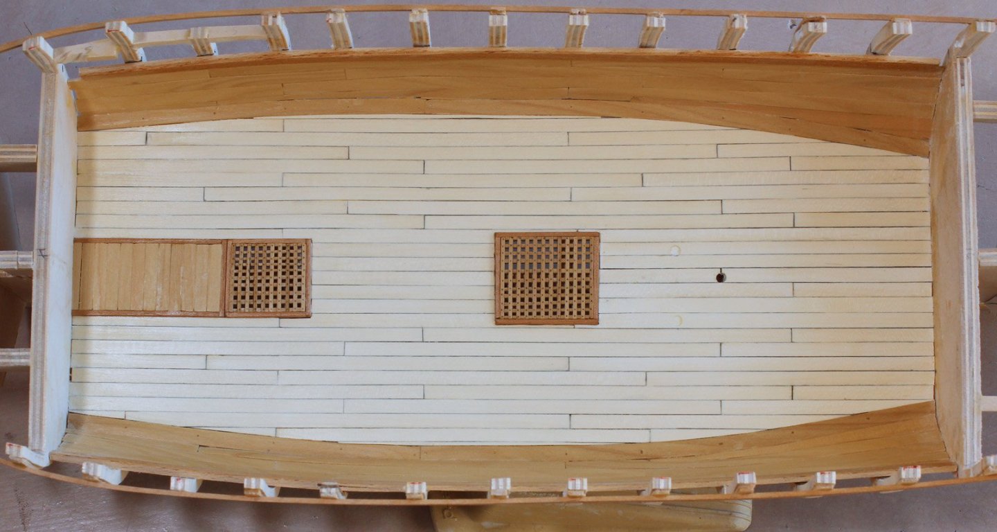
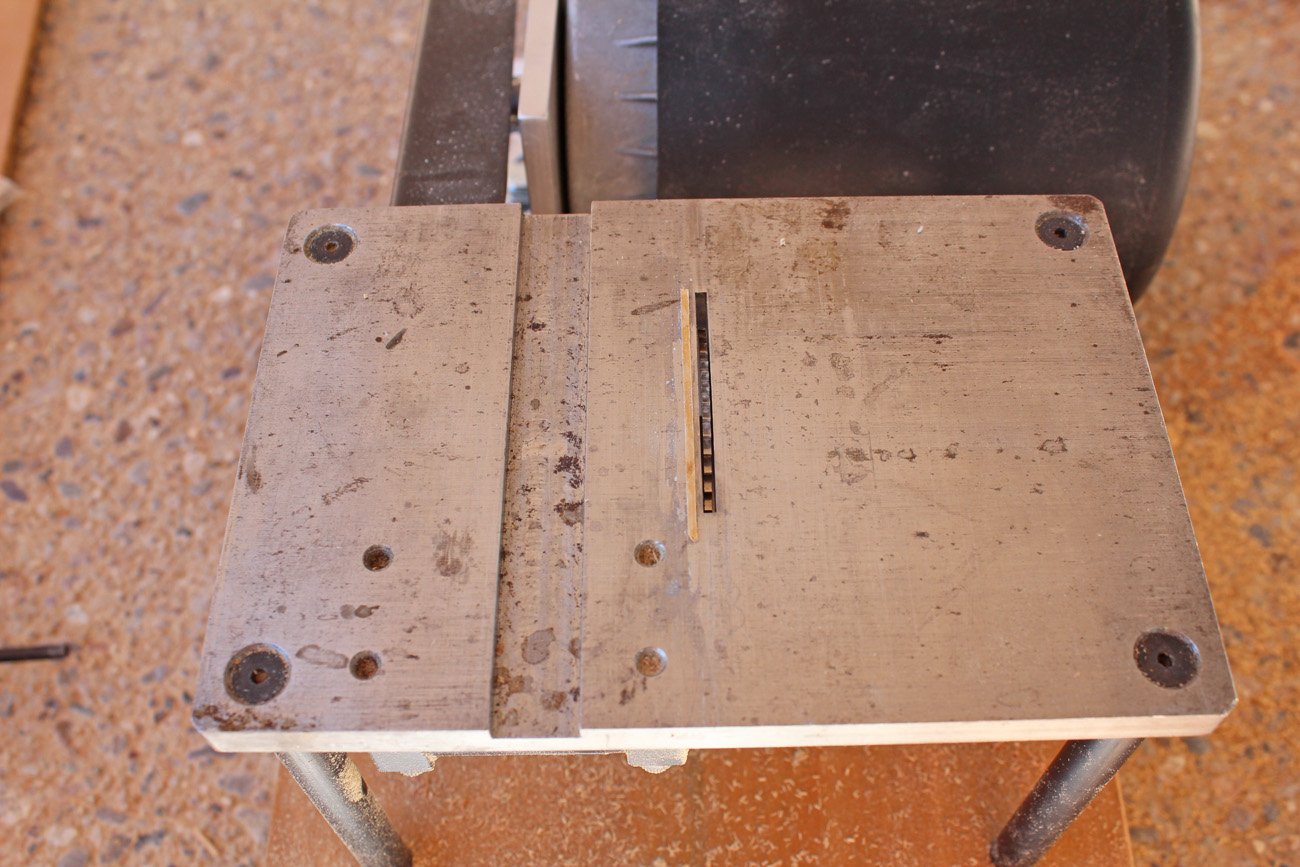
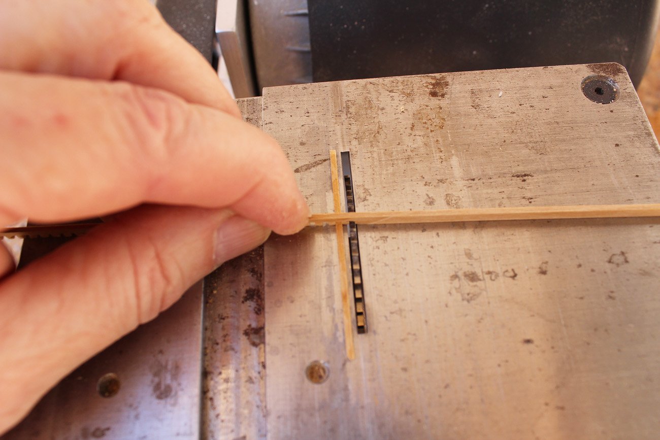
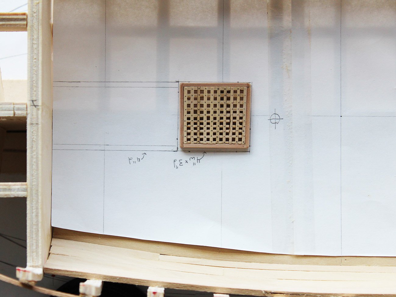
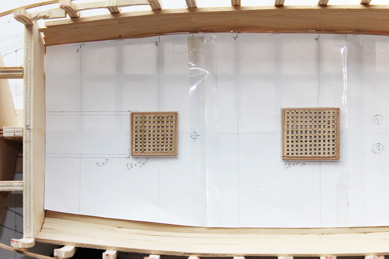
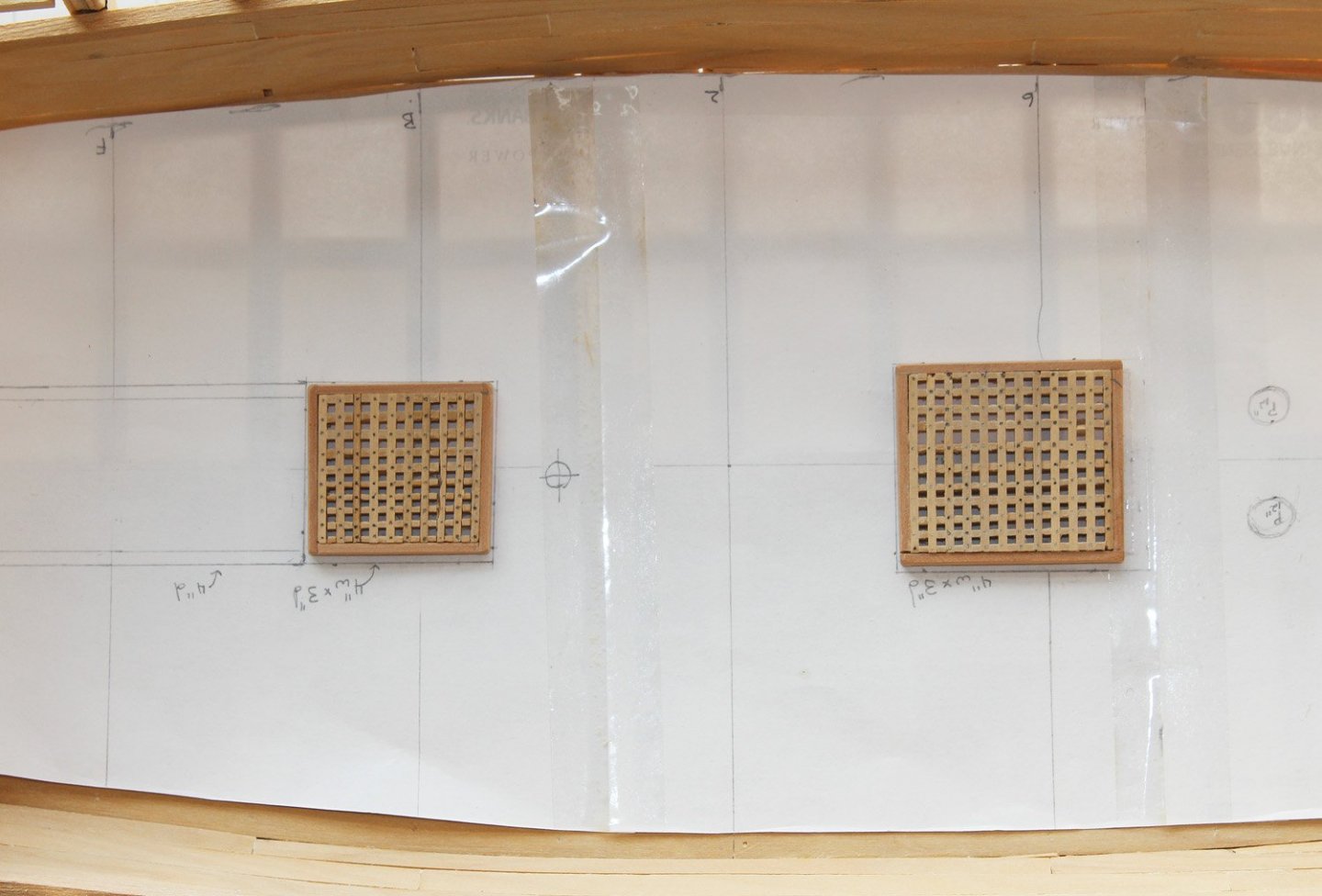
I realize it has been a long time since my last post but I will try to be better going forward. The lower deck has a fore and main hatch, a pad for the stove and a pad for the base of the capstan. I do not see any evidence of mast partners on the plans. There are also openings in front of the main mast for the pumps. The hatches are constructed next. Because this is a POB model, the frame construction is simplified from the prototype. A more complete description of hatch construction is located here: The gratings were made first and the frames made to fit the gratings. On a ship of this size, the ledges (the notched part of the grating) were 3.5" x 1" and the battens (the strips that fit into the notches) were 2.5" x 3/4". In order to maintain an even spacing between the notches, I CA'd a strip of wood the same width as the batten onto my Preac. Then, using a blade the same width as the batten (0.05") it was a simple matter to cut the strips of notched wood. I generally use two hands when cutting the notch but needed one hand to take the photo. The pictures show both hatches in position on the paper template. I simulated the treenails in the hatch grating by making a depression with the point of a compass and putting the tip of a sharp pencil in the depression. The pad for the stove was installed next, just in front of the fore hatch. This will be covered with an "iron" plate later.
- 277 replies
-
- 15
-
-
We all have those moments. We simply try to hide them!
-
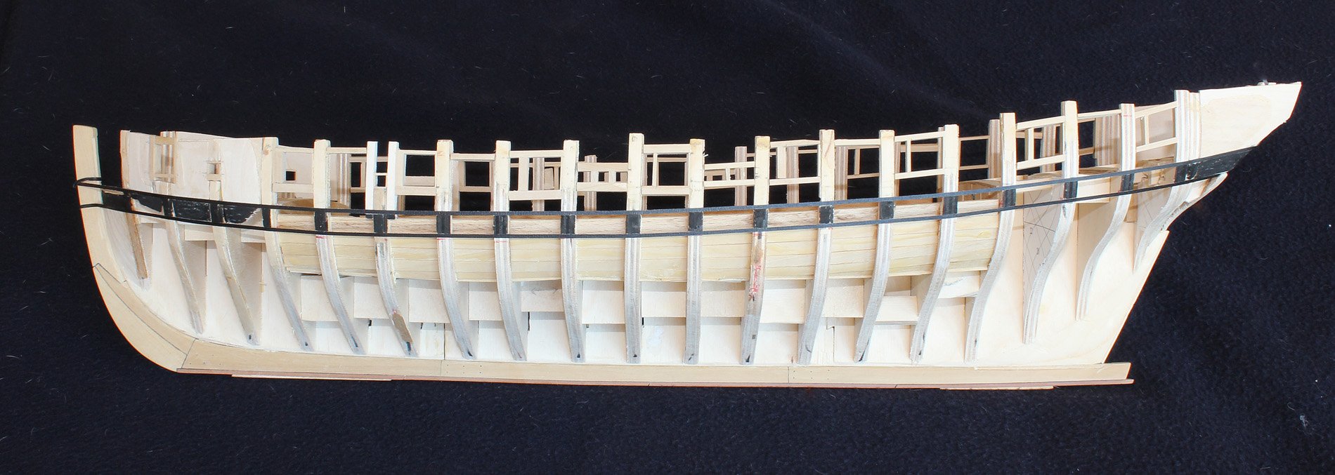
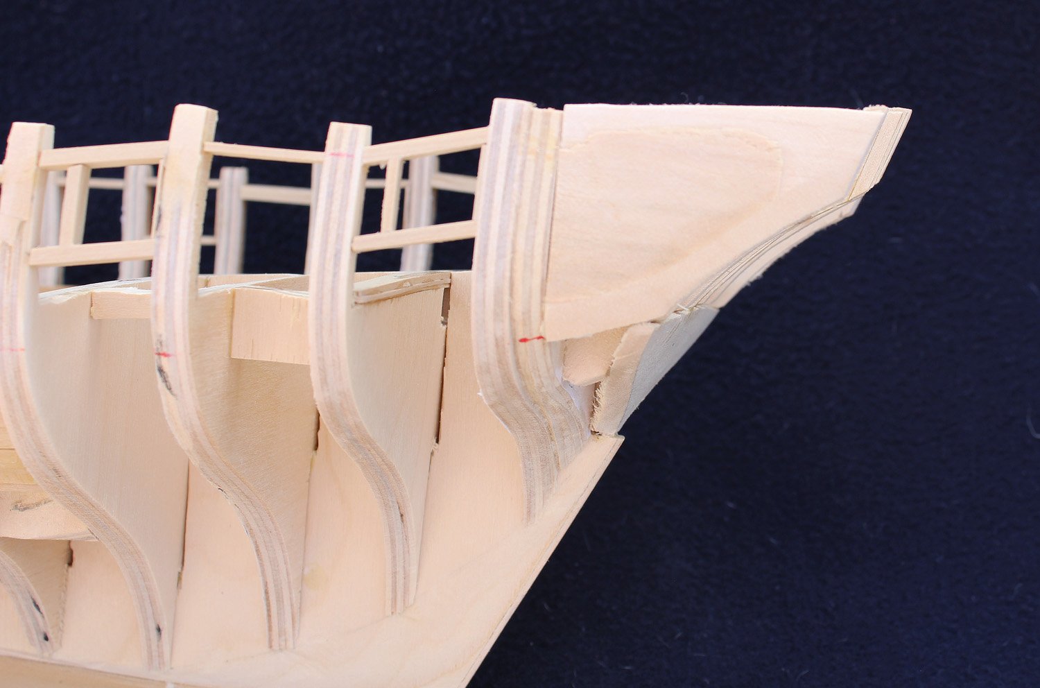
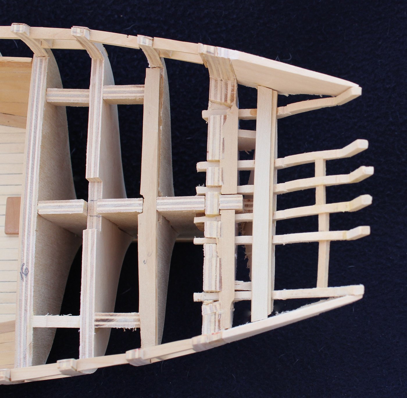
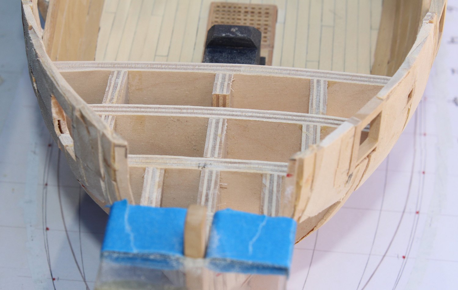
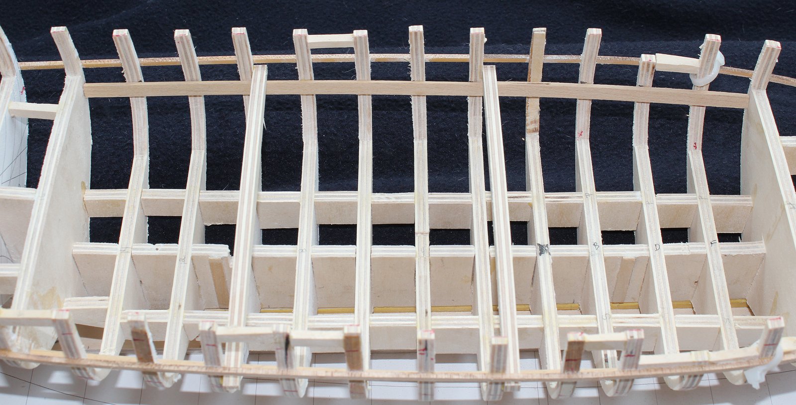
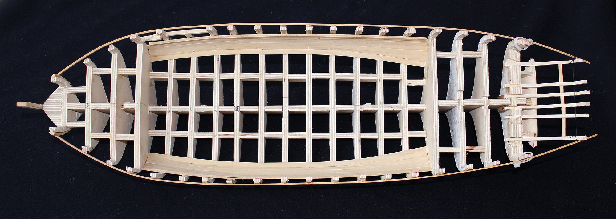
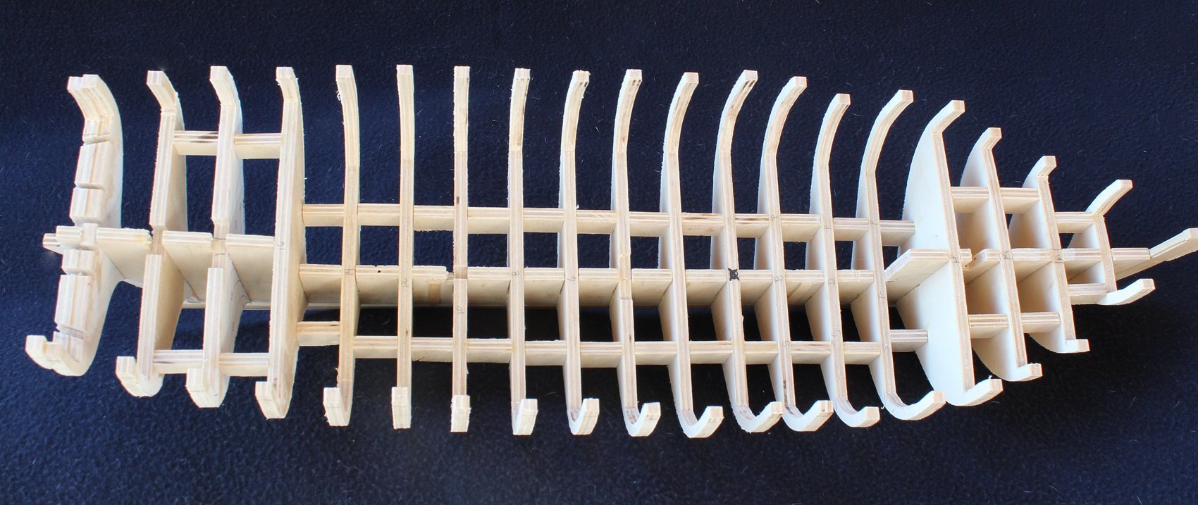
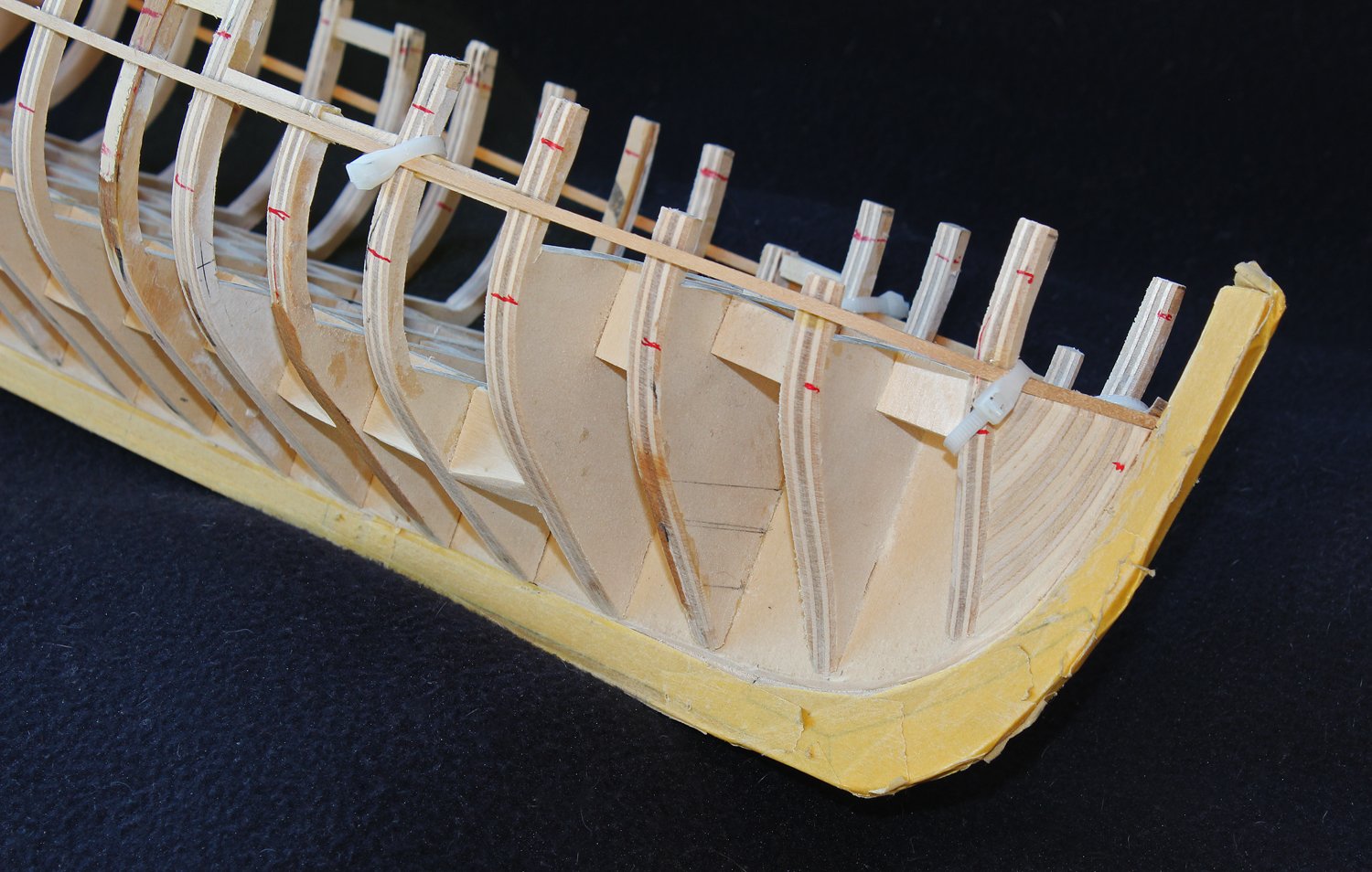
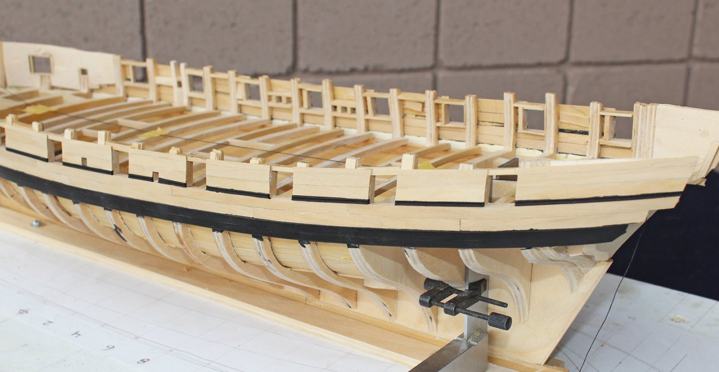
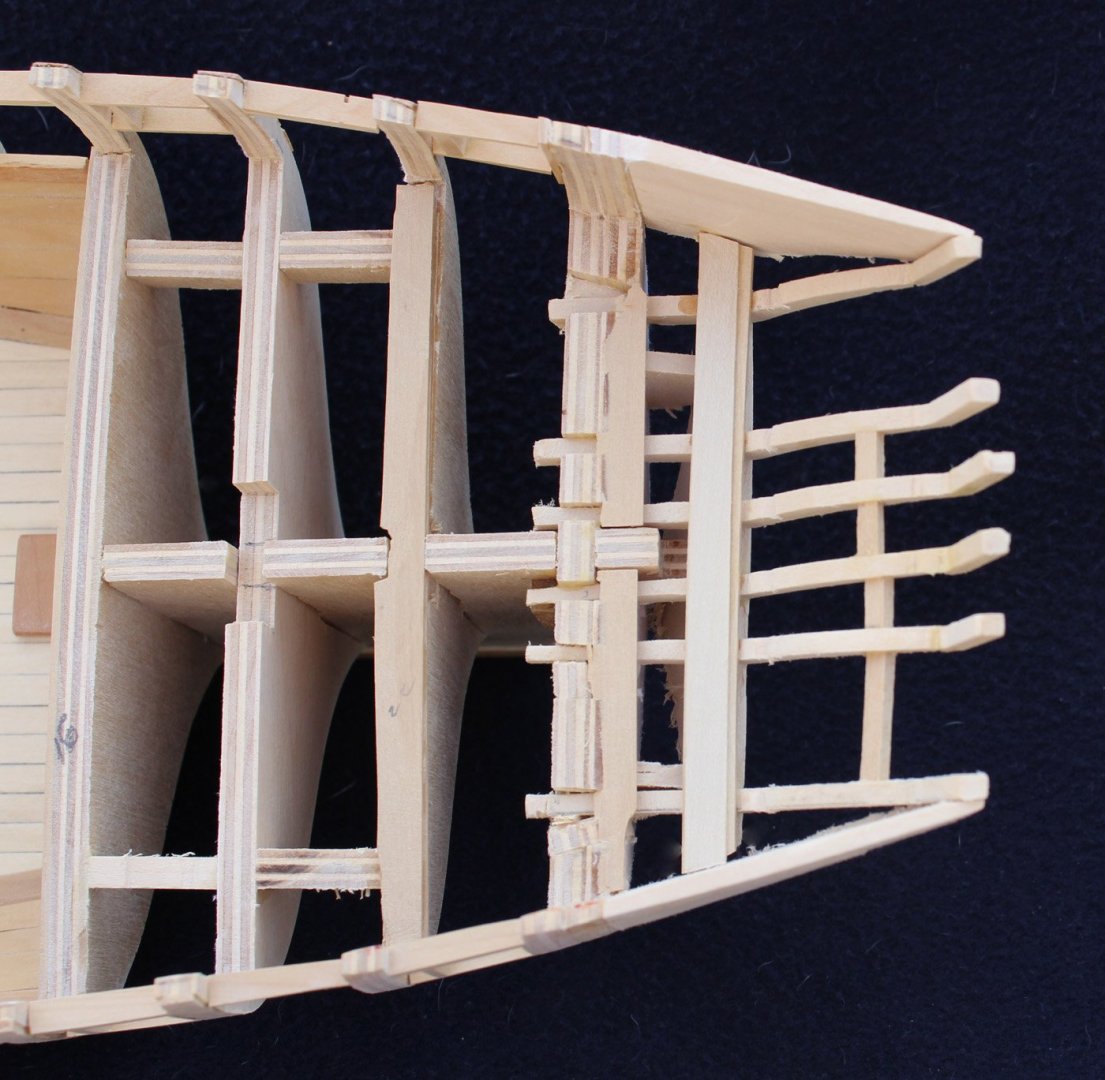
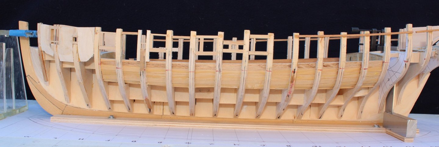
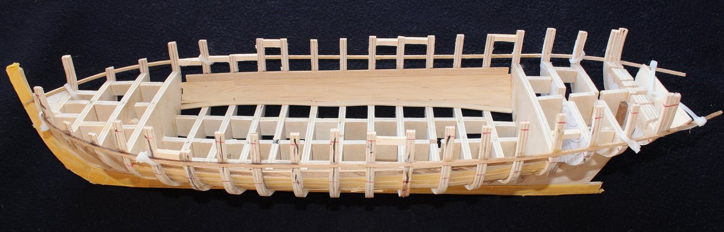
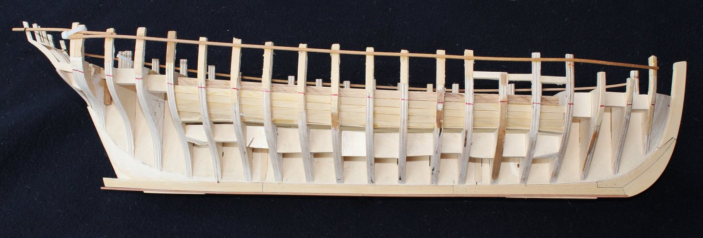
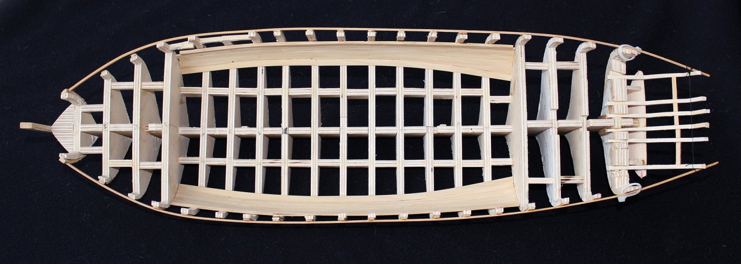
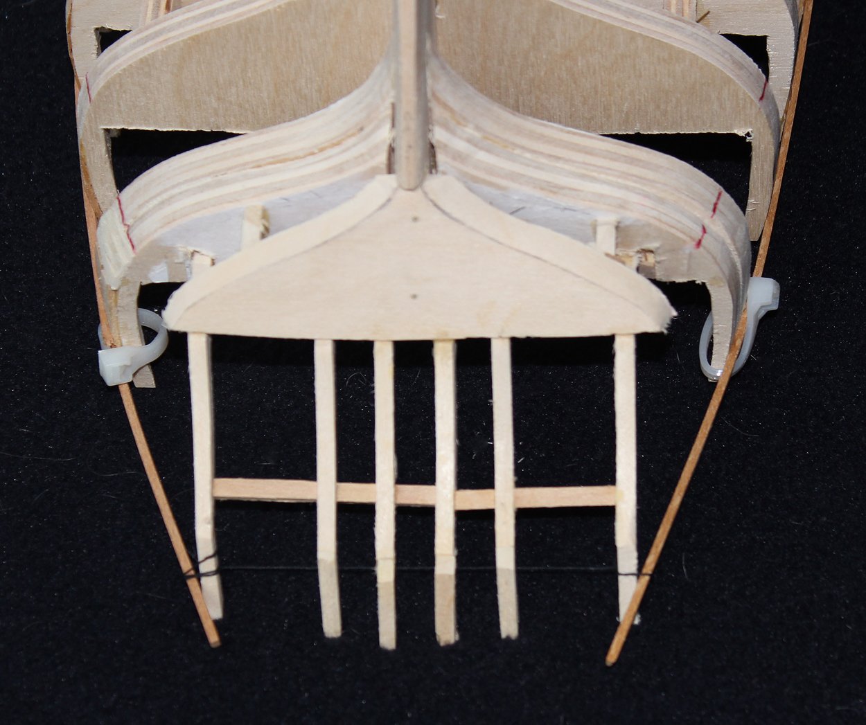
It has been a while since I posted an update but not for inactivity in the workshop. Once the hull was faired, I installed the upper deck clamps. These were made from beech because of its flexibility. This was also a good time to make the upper deck beams. They have a 6" roundup. Only the beams under the deck openings will be visible so these were made from costello; the rest were make from ply. Two of the beams were temporarily installed to prevent rotation of the hull. As mentioned previously, I plan on having the gratings for the hatches removable. The lower deck waterway was installed next. Although the ability so see details on the lower deck diminishes the further you get from the midline, I decided to install waterways and ceiling timbers. All of these were made in costello. However, because the inner hull will barely be seen, these planks were edge-bent rather than spiled. The apparent irregularity in the waterway of the first photo is an optical illusion, as it is not seen in the second photo. I was preparing to install the transom and the counter timbers when nothing started to make sense. I double checked all of my measurements, both against the CAD drawing and the original plans and discovered that although I had done a beautiful job of fairing the outside of the hull, the tumblehome was too great by approximately 4". This left me two options: keep going and simply build a slightly inaccurate hull or laminate extra wood onto the bulkheads and start the fairing process again. The first option was unacceptable to me and so I spent another week undoing my error. The transom/counter timber assembly is next. The transom took only three attempts to get right. My initial attempt was the alarm bell informing me that the fairing was incorrect. My second attempt utilized a transom configuration from my CAD drawing; this was too small. Finally, I took an over-sized piece of basswood, installed it and shaped it based on the curvature of the hull. What I discovered was that the shape of the aft surface of the transom was almost identical to the shape from the CAD drawing. Two brass pins secure it to the backbone. I installed the six counter timbers into slots in the aft bulkheads. Thread is tied between the ribbands to maintain the correct curvature. This will facilitate fabrication of the filler pieces. There is still some fairing to do on both sides but I will hold off on that until the lower deck is completed.

- 277 replies
-
- 25
-
-
HMS FLY by cafmodel - 1/48
tlevine replied to cafmodel's topic in - Build logs for subjects built 1751 - 1800
Yes, they are both Swan class ships. -
HMS FLY by cafmodel - 1/48
tlevine replied to cafmodel's topic in - Build logs for subjects built 1751 - 1800
Those perspective drawings would have been nice to have while I was building Atalanta. Beautiful work. -
And here I am, looking at going to a warmer climate after retirement. Although this winter in Chicago has been unbelievably warm. Martin, I agree that you are stuck with casing the rigged models. However, If you are going to move them yourself, the enclosure can be made of pegboard or even cardboard. Many years ago I moved cross-country with three fully-rigged models in cases made of cardboard boxes. Aligned along the back seat of our Datsun they gave each other support and prevented tipping.
- 467 replies
-
- 1
-
-
- fly
- victory models
- (and 1 more)
-
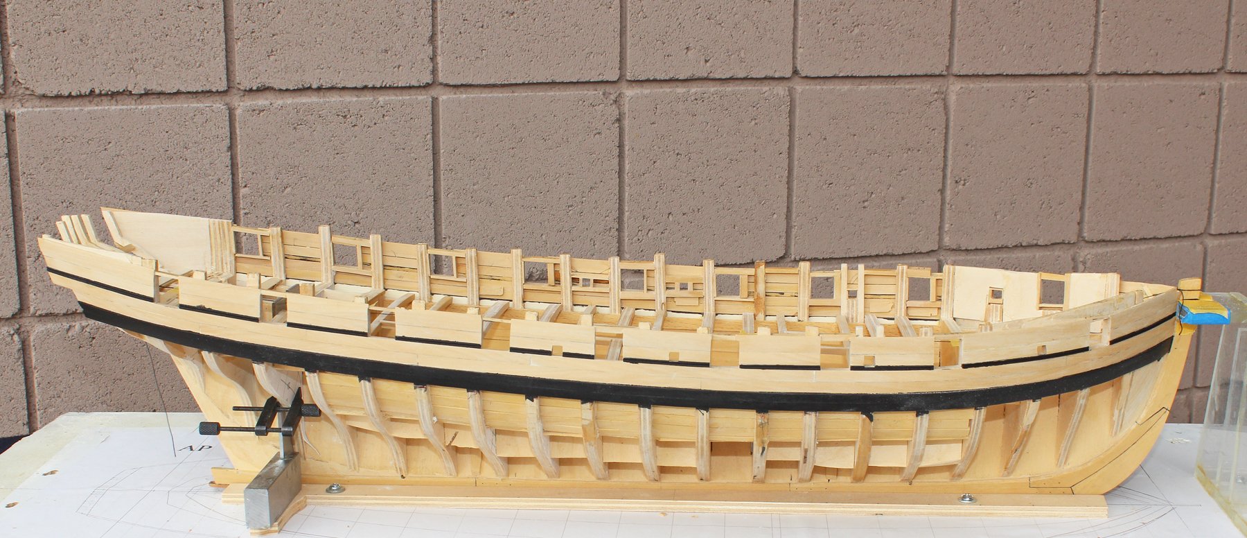
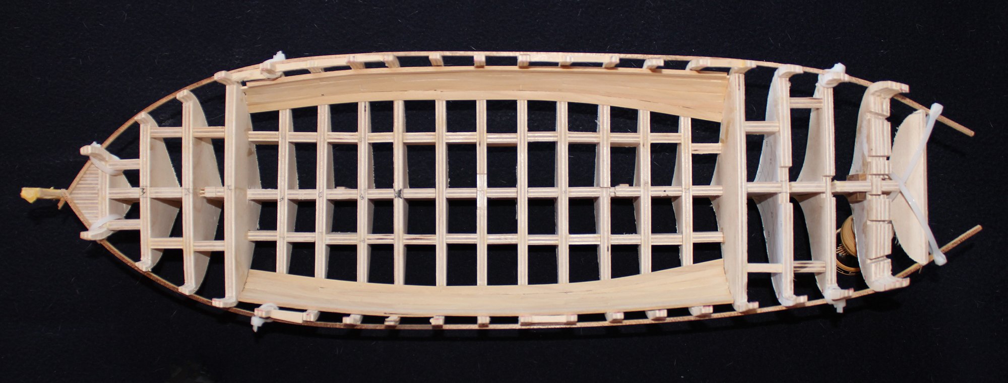
The figure head looks great. As far as moving the model, I took Atalanta from Chicago to Las Vegas and back for the 2018 Conference without any mishaps. Here is my suggestion... Make a building board which is a few inches wider and longer than the model. Take a look at mine for an example. Drill holes on either side and run wire through the holes and over the top rail (after protecting with with a towel). Tighten the wire and you're done.
- 467 replies
-
- 2
-
-
- fly
- victory models
- (and 1 more)
-
HMS FLY by cafmodel - 1/48
tlevine replied to cafmodel's topic in - Build logs for subjects built 1751 - 1800
This is a link to purchasing the framing plan for a Swan class ship from the Royal Museum Greenwich. This illustrates Druxey's comment that the frames are not all the same width. http://images.rmg.co.uk/?service=asset&action=show_zoom_window_popup&language=en&asset=27396&location=grid&asset_list=11336,11337,11338,16317,34837,34834,34835,27396,34838,34836,24580,20676,21494&basket_item_id=undefined -
Looks sweet, Dan. You will eventually use that same sanding disc on the tops of the bulkheads.
-
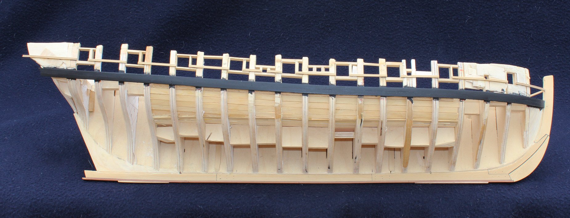
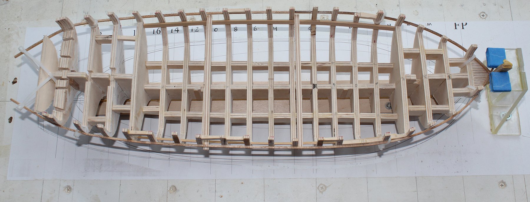
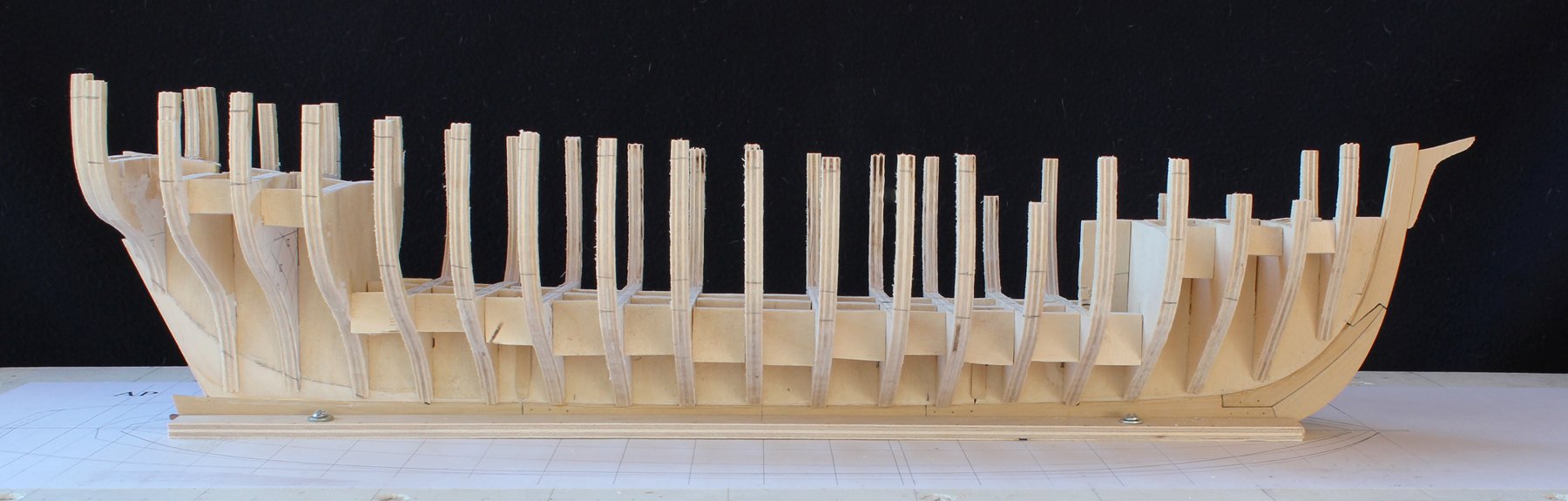
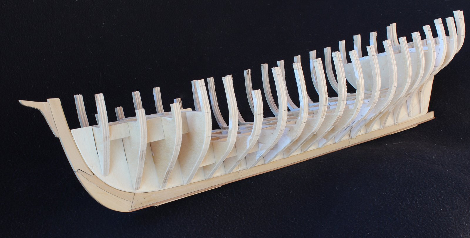
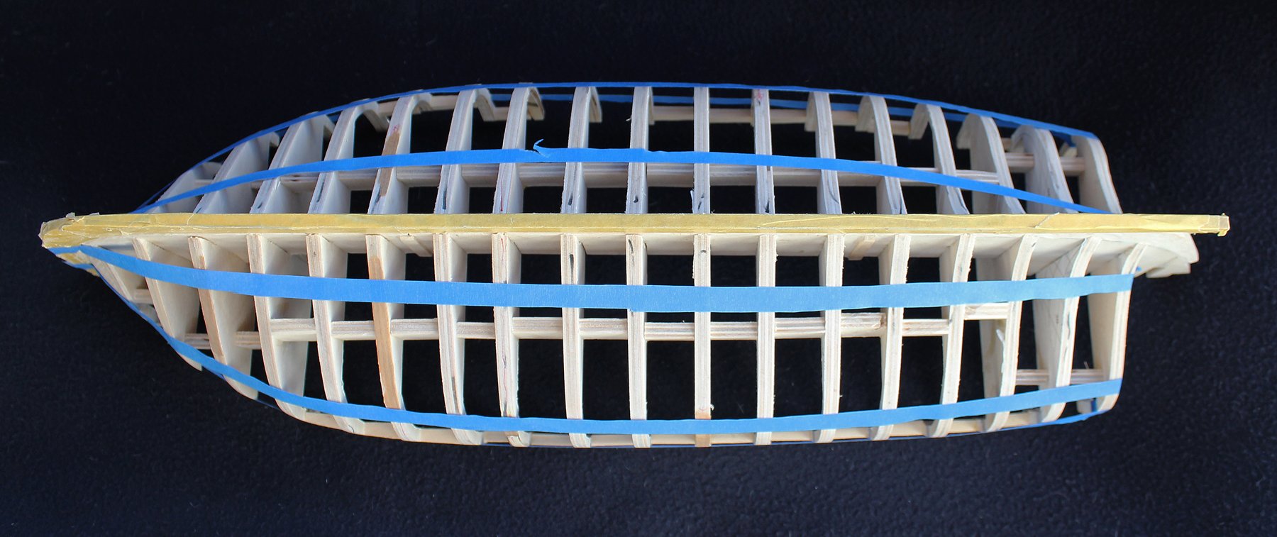
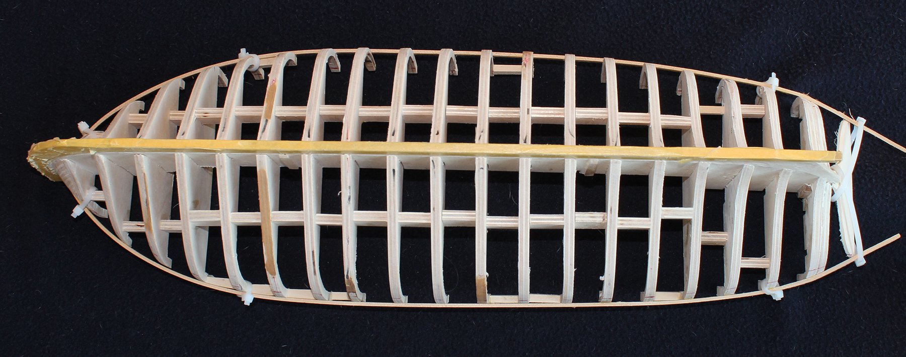
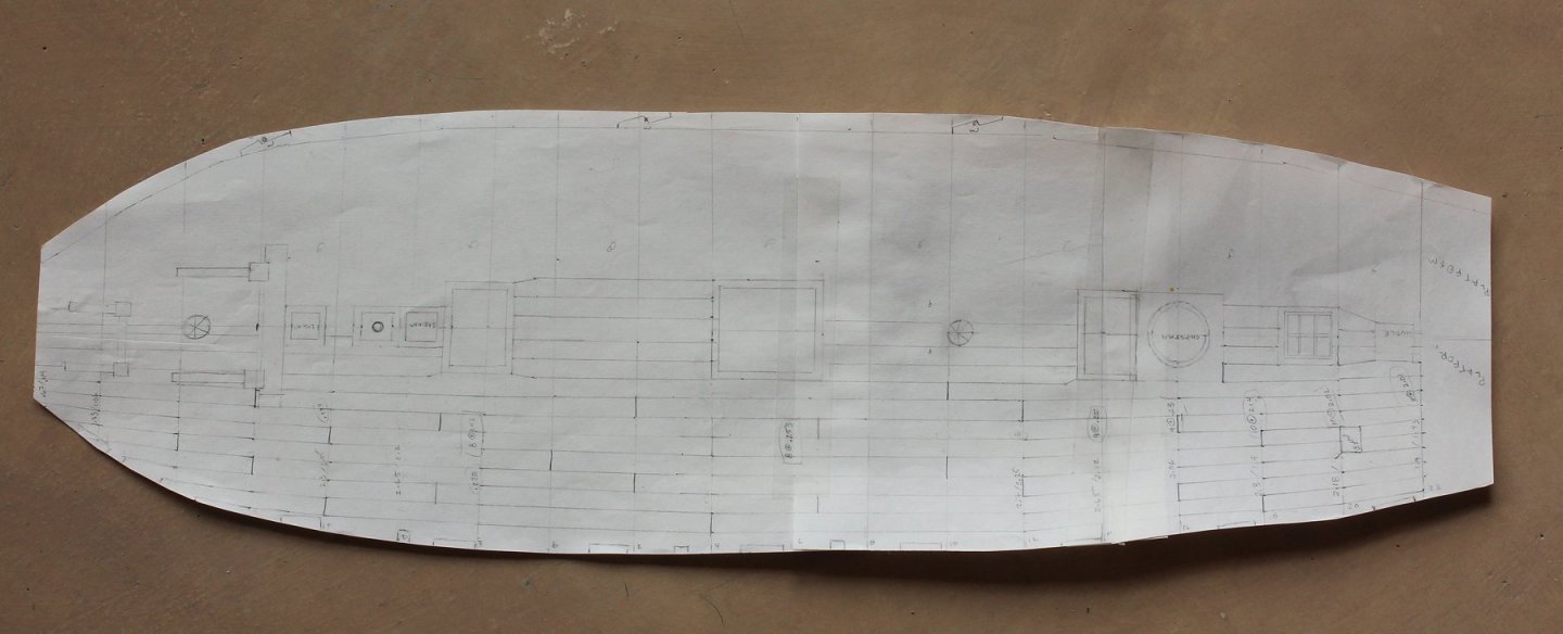
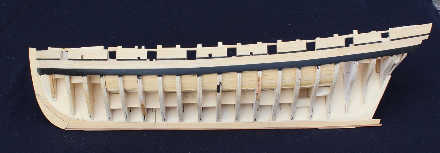
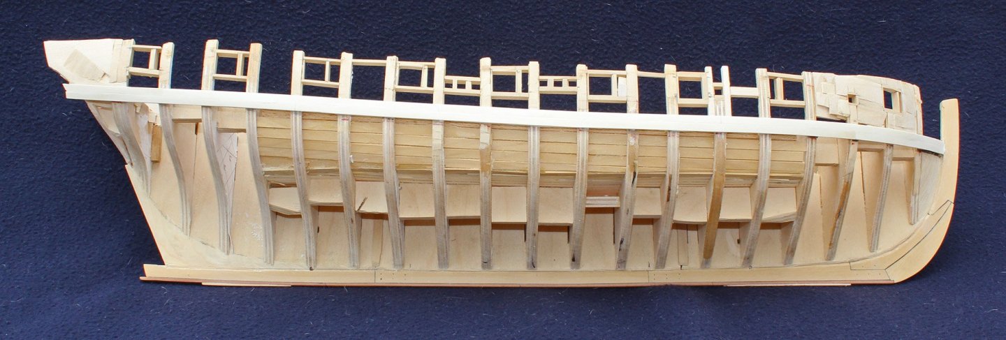
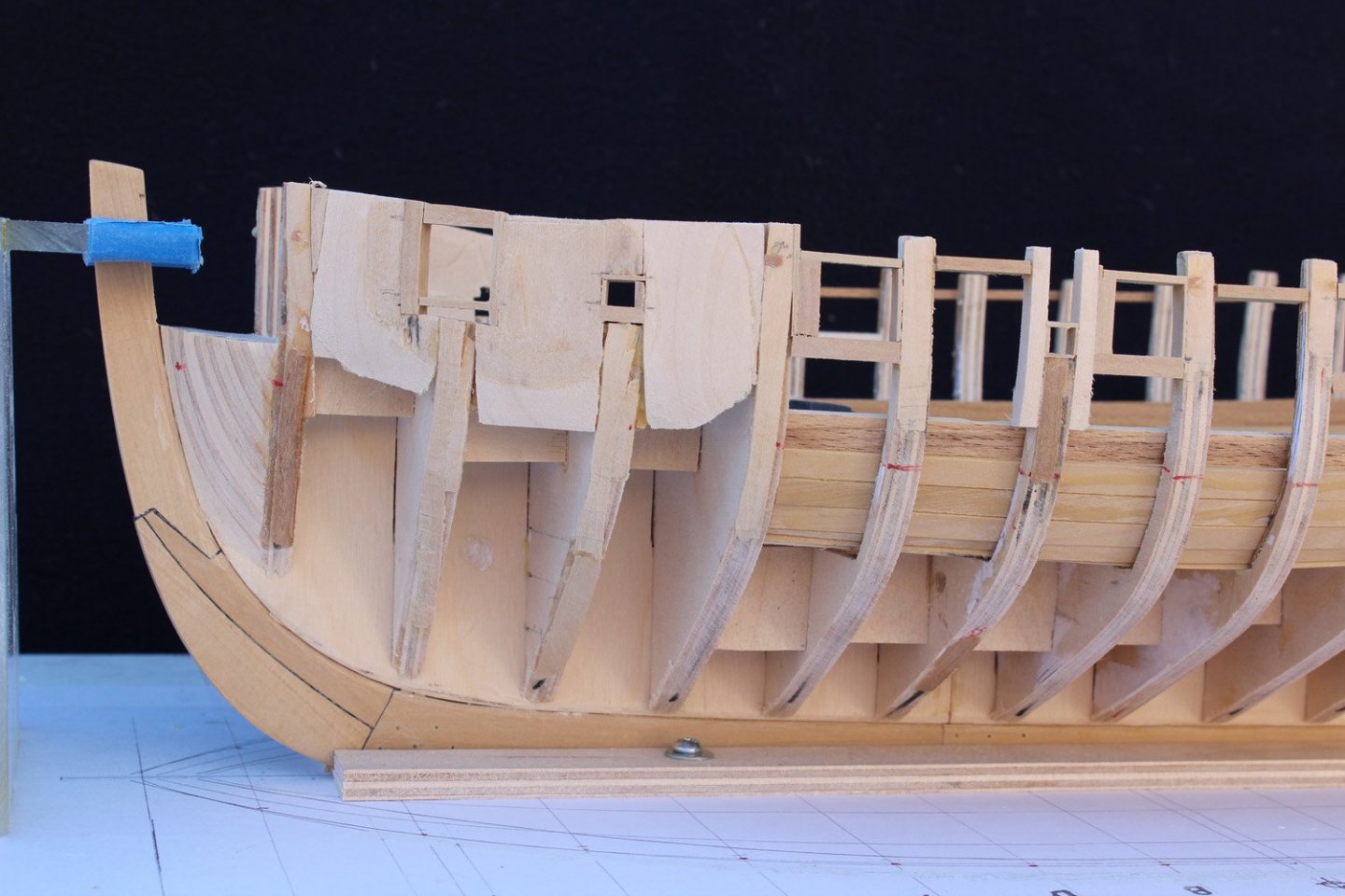
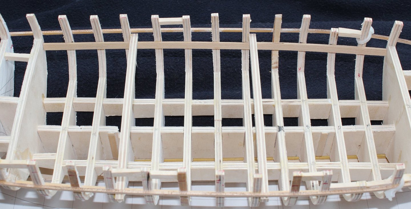
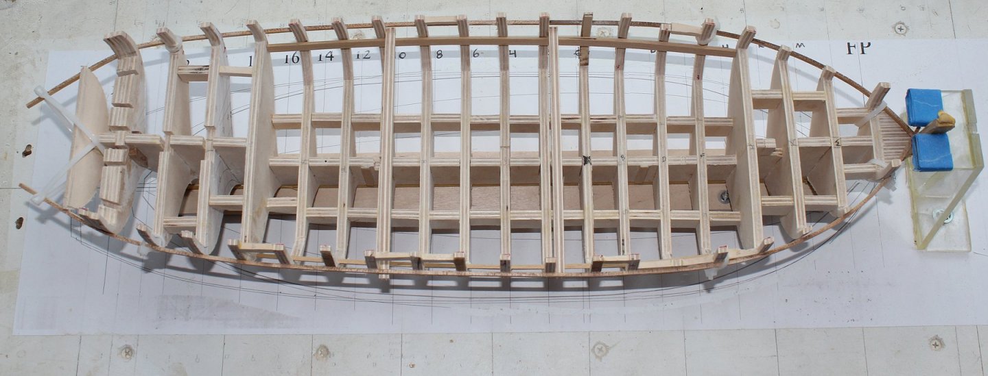
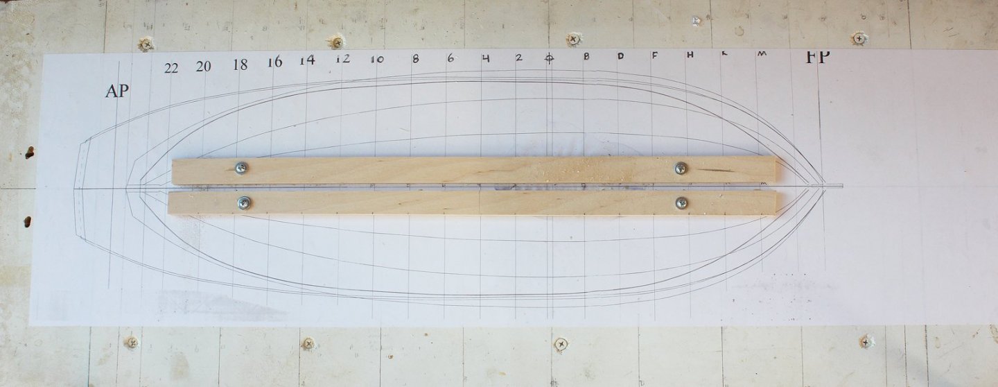
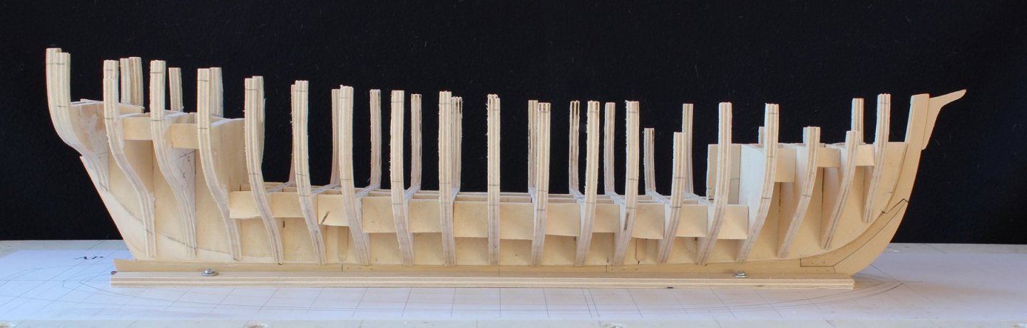
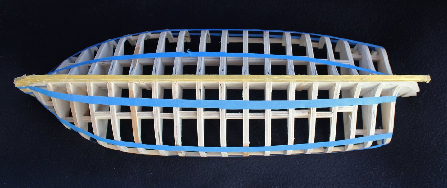
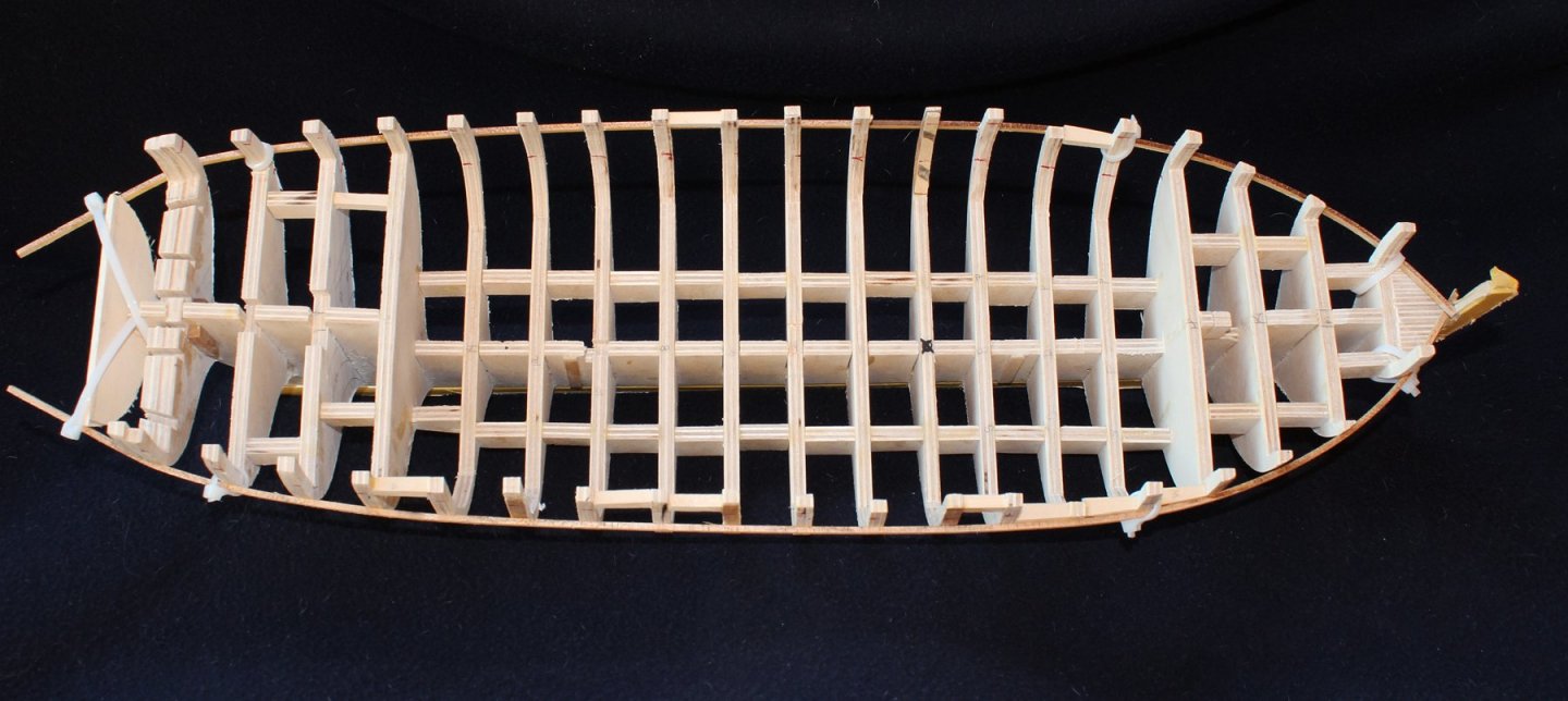
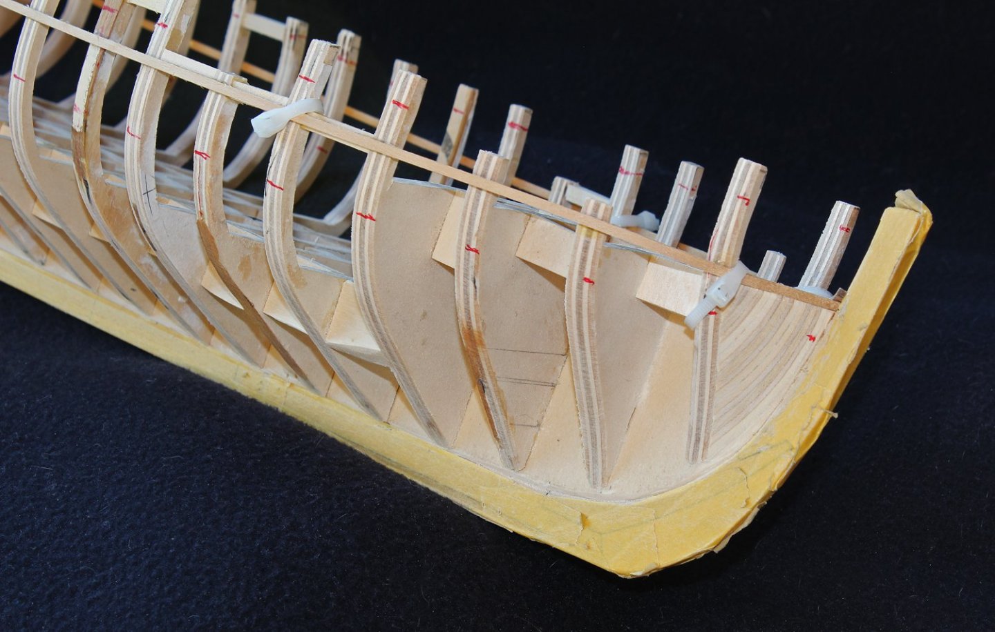
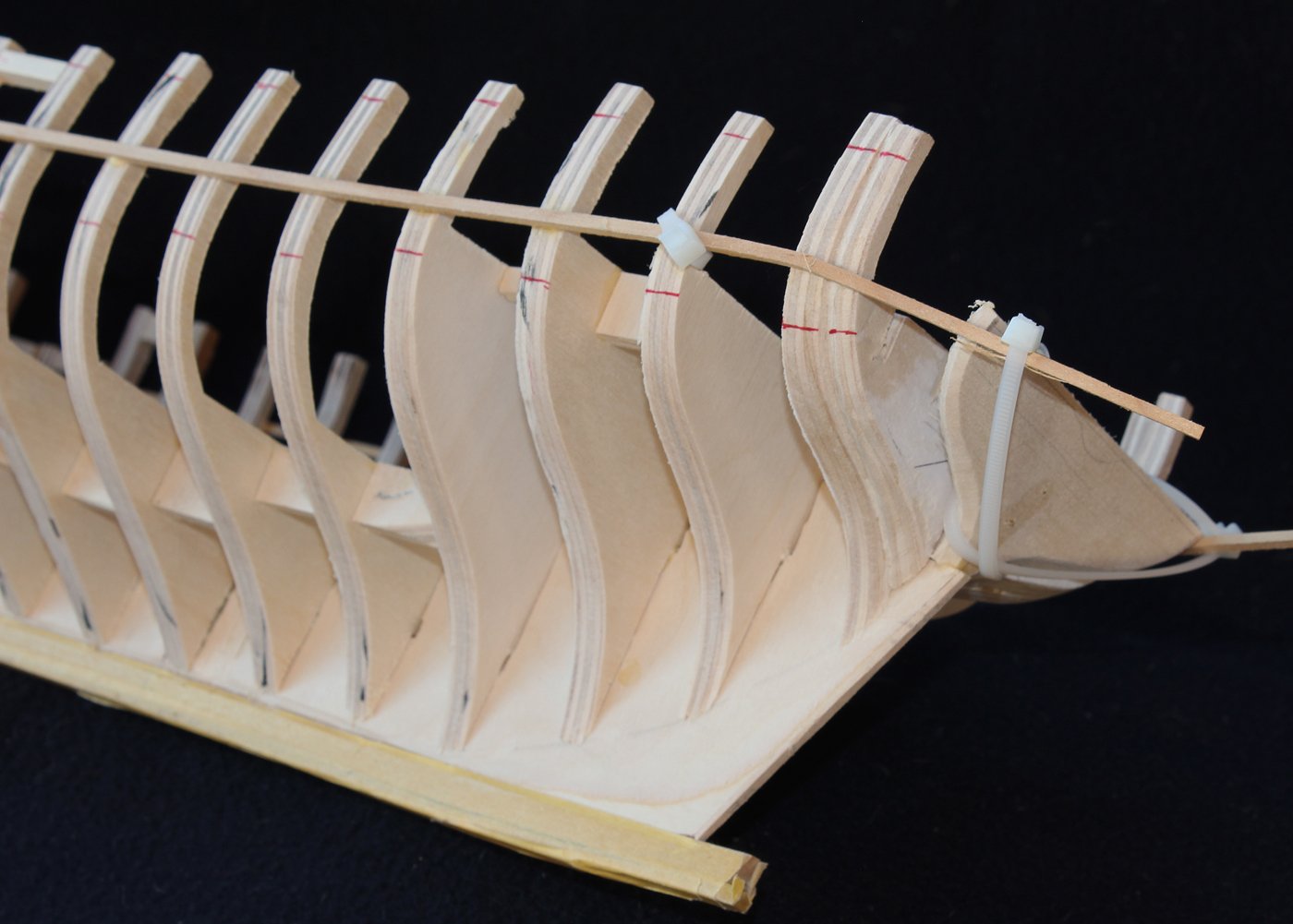
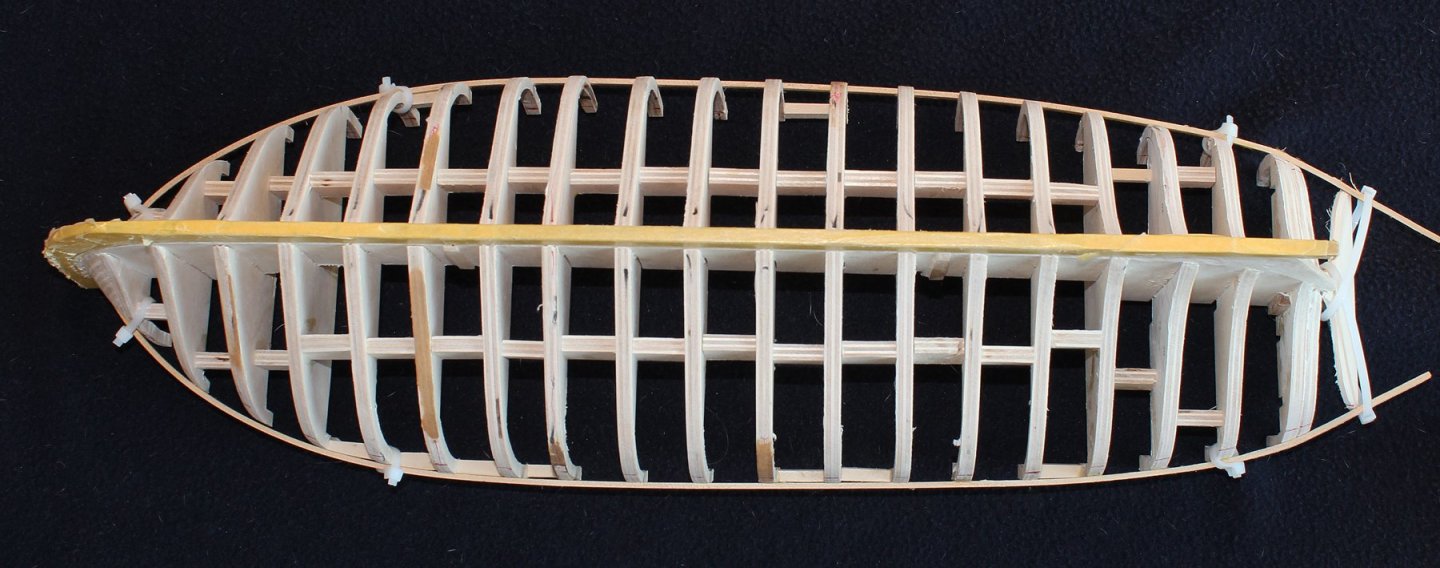
It has been a while since I updated the log but installing bulkheads and fairing a hull just is not very exciting. The fist step in permanently installing the bulkeads is making a building board. This will secure the keel so that the bulkheads (hopefully) will be installed plumb and square. I was able to reuse my building board from Atalanta and simply glued Swallow's waterline plan to the board. I secured two strips of wood on either side of the midline with oversize holes to that they could be snugged against the keel. The bulkheads were cut from 1/4" basswood plywood. I plan on constructing the lower deck amidships so the center of bulkheads F through 14 only extend to the level of the lower deck. The other bulkheads extend to the upper deck. The bulkheads were installed using the same technique seen in the half hull project, clamping them to machinist squares. I also keep a small level on the bulkhead while the glue sets. This becomes most important with the bulkheads that only extend to the lower deck; there is only a narrow slot so it is easy to get them out of plumb. Once all the bulkheads were in place, spacers were installed to stiffen the hull in preparation for fairing. I use a combination of techniques to fair the hull, including sanding discs on the Dremel, sanding blocks and files. One thing which is very helpful for the concave surfaces in the stern is rolling sandpaper around one of the rubber sleeves from my spindle sander. Before I owned the spindle sander I would use a shot glass. The key in fairing a hull is taking a lot of breaks. It is too easy (for me at least) to remove too much wood otherwise. On this hull you can see a few places that happened. Those spots were built back up with strips of walnut from the scrap bin. One techniqe I use to check for a fair run is to take strips of masking tape and run them along the hull. Another useful technique is to run a marker along the bulkhead. As the hull approaches fair, the marker is gradually sanded away. At this point I am reasonably satisfied with the shape of the hull. Several of the spacers become loose during the fairing process. Rather than replacing them, I ran a ribband along the hull, gluing it in place and then securing it more with zip ties. The red marks represent the wale and the bottom of the rail. The plans show the gunports extending to the rail but the model shows an additional row of planking above the ports. I have not decided which direction to go at this point. Neither the plans nor the model are "as built" and it was common to add the extra row of planking to help protect the crew.


- 277 replies
-
- 26
-
-
Doug, any problems will be taken care of with the fairing. Did you apply glue to the part of the frame that touches the plan? That, along with gluing the mating surfaces of the wood, should hold it until you install the filler piece.