HOLIDAY DONATION DRIVE - SUPPORT MSW - DO YOUR PART TO KEEP THIS GREAT FORUM GOING! (Only 13 donations so far - C'mon guys!)
×

tlevine
-
Posts
2,032 -
Joined
-
Last visited
Content Type
Profiles
Forums
Gallery
Events
Everything posted by tlevine
-
 The forecastle deck probably had stanchions supporting a line to which netting is fixed. The object was to prevent sailors from being as easily swept overboard. I have been unable to find any information as to whether this netting would be located outside or inside of the timberheads. Any thoughts? The contemporary model of Atalanta does not show these stanchions.
 -
Swann-Morton Scapel
tlevine replied to Landlocked123's topic in Modeling tools and Workshop Equipment
Instrument tying is often superior to hand tying. It allows me to get into tight areas that even my small hands would find difficult. Once you get the feel for the correct amount tension to apply for the type and weight of the material, it is just as secure as hand tying. -
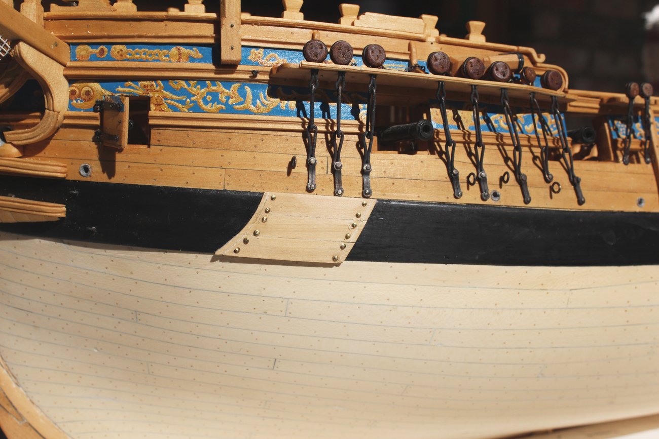
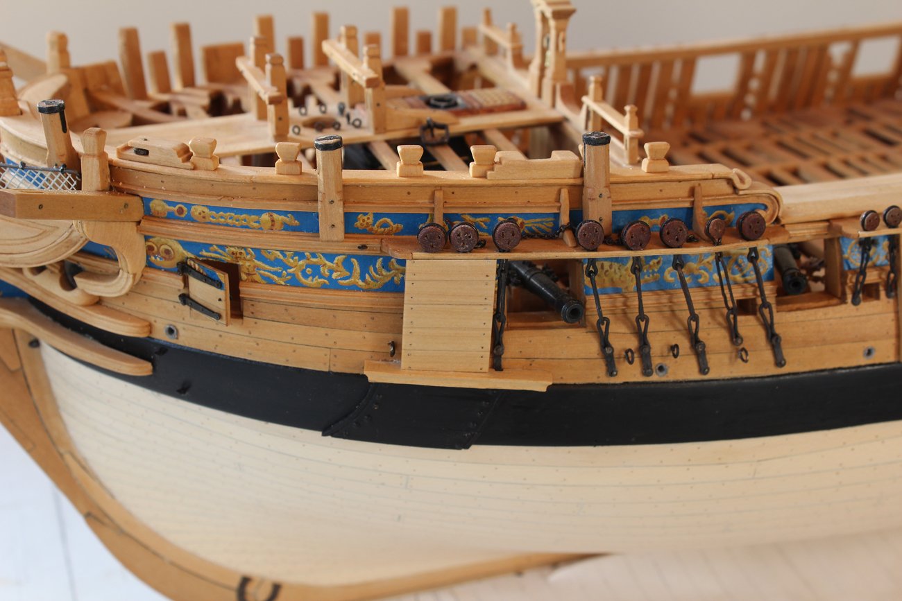
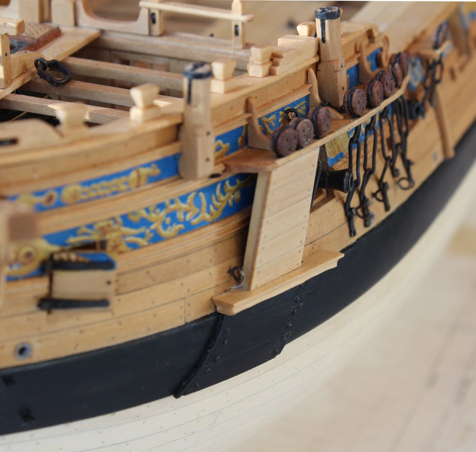
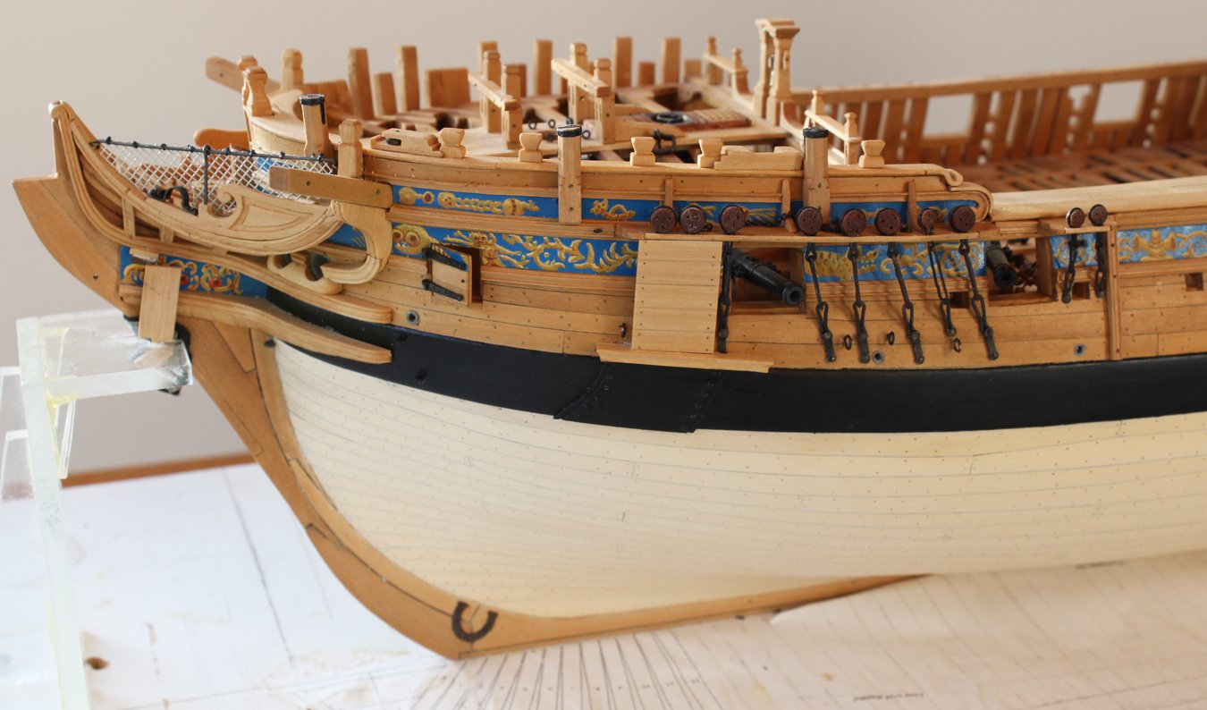
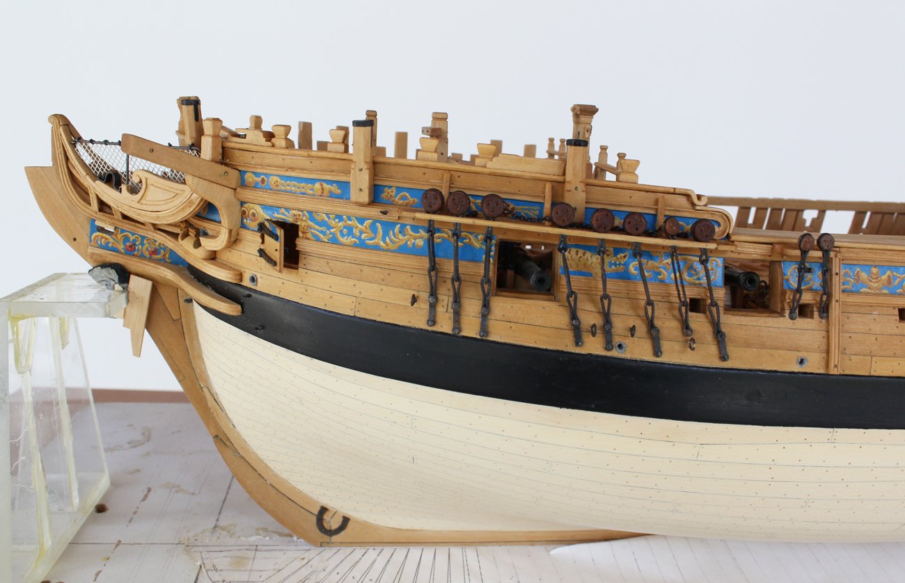
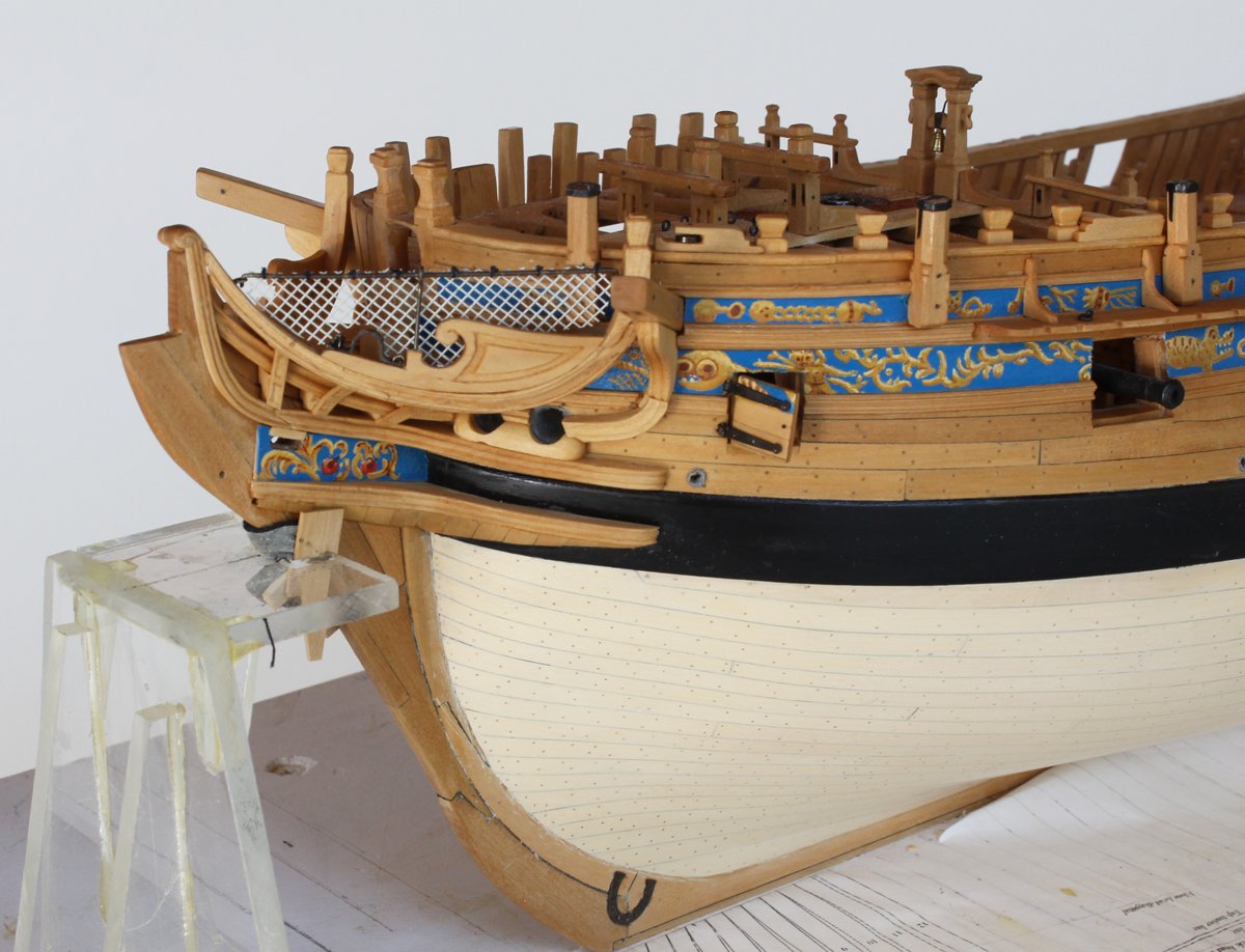
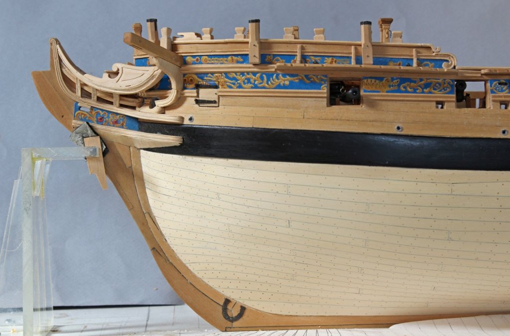
Ed, never apologize for your books. They are bibles for many of us. The covering boards and bill boards are an attempt to prevent injury to the hull and chain plates while hoisting the anchor. Both of these structures are designed to be easily replaced. On the Swan class the lining overlaps the main wale. There are three of them and they are attached with nails whose heads stand proud for easier removal (I think). There is a decorative groove near the lateral edges. In order to get a smooth run for the groove, I made the lining off the model, gluing the the boards together on a piece of paper for extra support. Then I cut the groove. I removed them from the paper and glued and nailed them to the model. The lower two boards required bending in two planes to fit the wale tightly. After listening to everyone's advice I decided to paint them. I found the appearance of the bright wood garish against the black wale and decided any commanding officer would feel the same way. There is a molded platform on top of the lining is wide enough to allow a man to stand on it. Access would be through the gun port. The bill board has two vertical stanchions to which the boards are attached.


-
US Brig Syren by knightyo
tlevine replied to knightyo's topic in - Build logs for subjects built 1801 - 1850
I vote for the pear. The basswood is too light. Once the finish is applied, the end grain will give it subtle contrast. -
Thank you Druxey. All of the photos of contemporary models I had were of larger ships so the wale was not at risk from the anchor. Ed, your thoughts are greatly appreciated. In fact, I used your approach as shown in the Naiad books to make my cutter. Although I did not mention it, the under surface is cut back to minimize the area which is in contact with the wood.
-
I am in the process of constructing the lining and bill board. On a Swan class, the lining overlays the main wale. Would it have been painted to match the wale or left bright?
-
Thank you gentlemen for your thoughts. Definitely, I will go for a different wood next time. As I am not rigging her, the smallest size deadeyes are the 7" ones. I have actually finished all of the deadeyes. Once the tung oil finish is applied, a little 400 grit sandpaper takes care of any fuzz. As it is an oil based penetrating finish, I can put the entire assembly through the blackening process without damaging the deadeye. Once installed on the hull, I applied an acrylic clear matte finish coat to the links. Kurt, I wrap a little masking tape around the tips of some needle nose pliers. I have never heard of nylon jawed pliers.
-
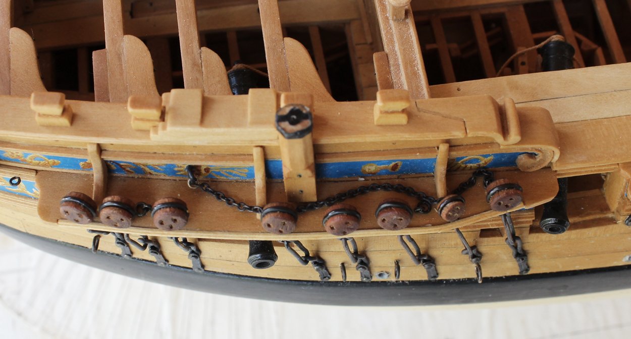
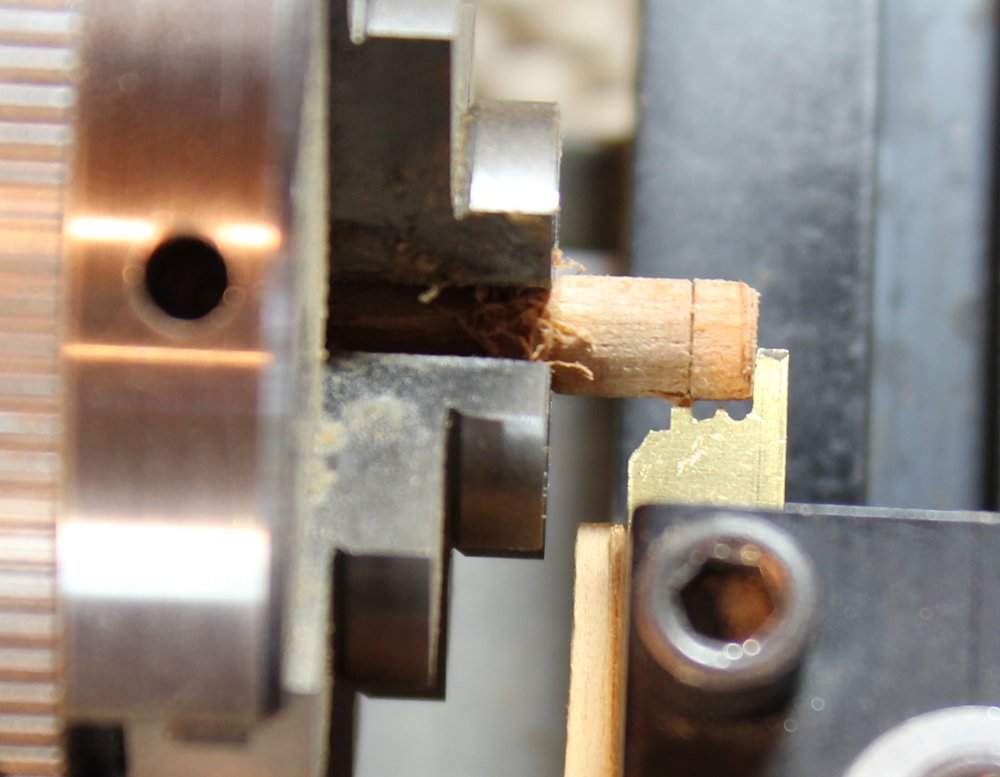
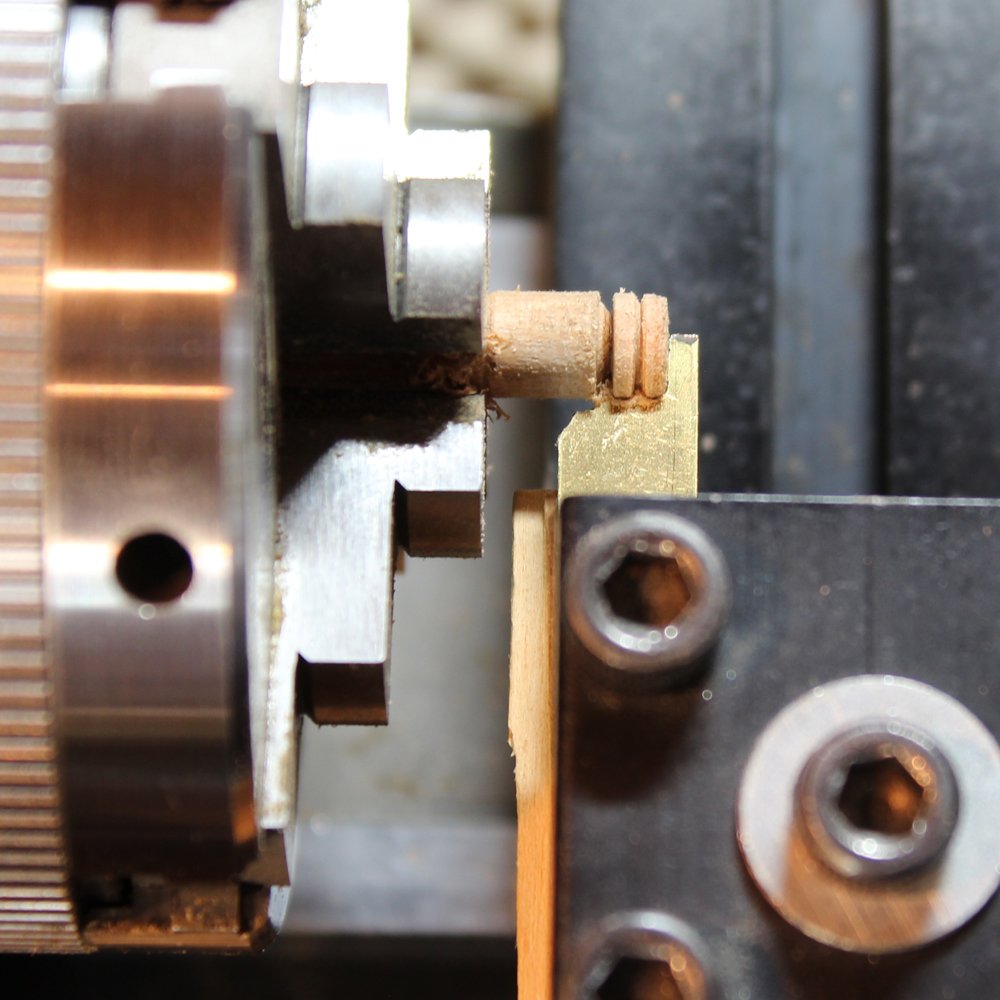
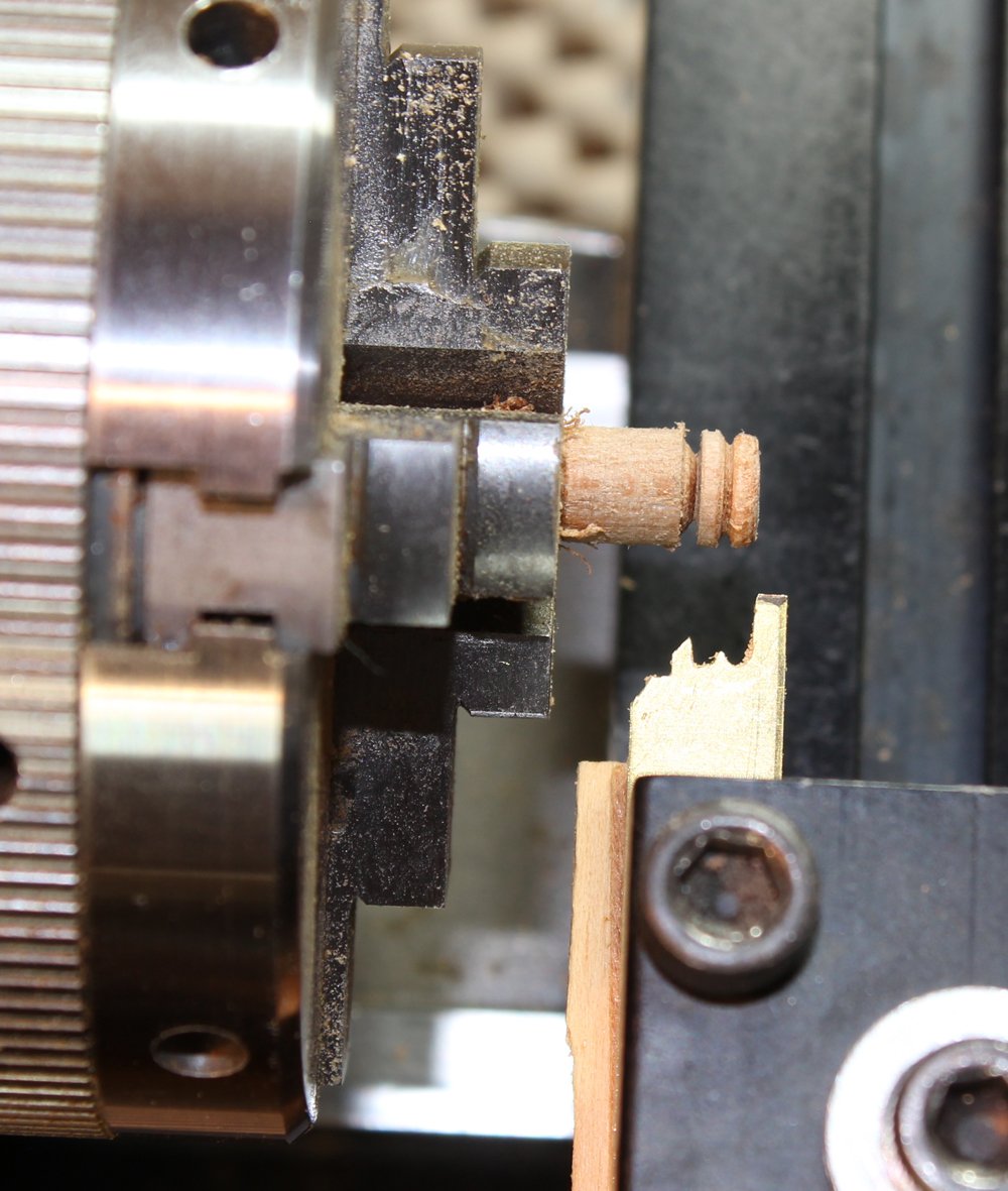
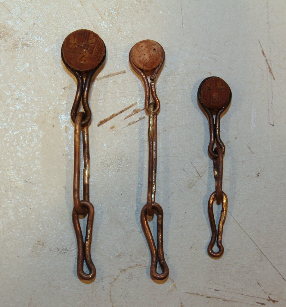
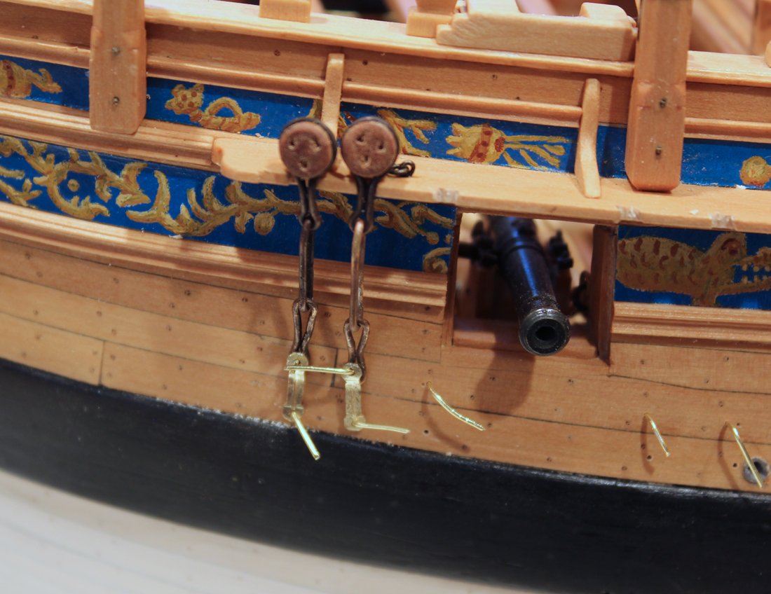
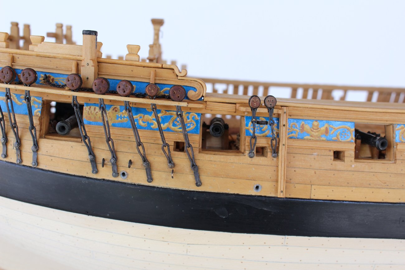
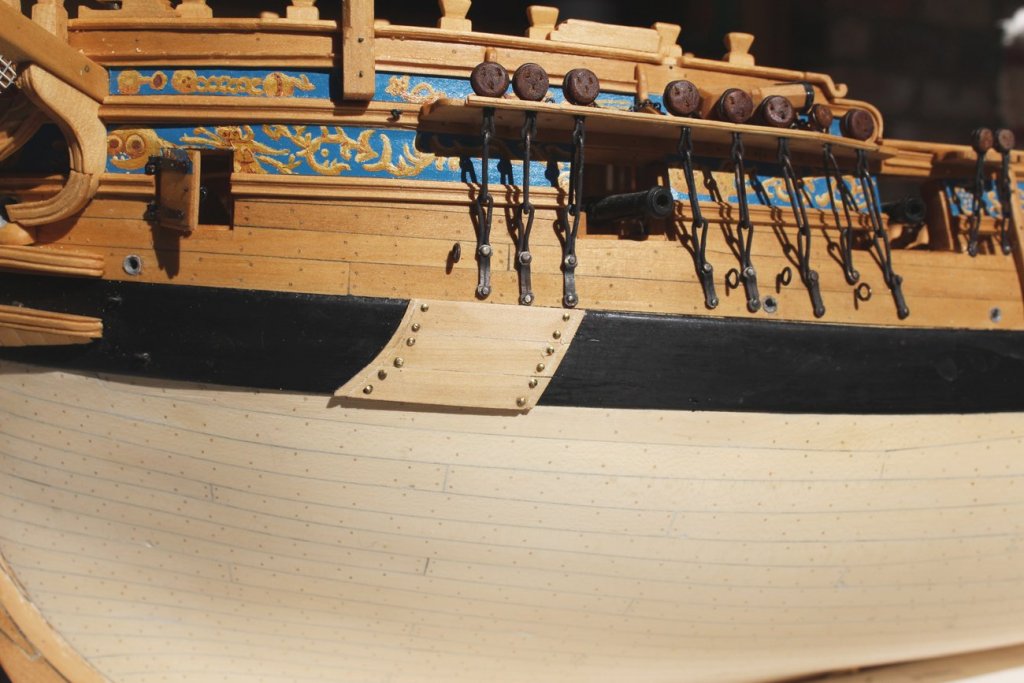
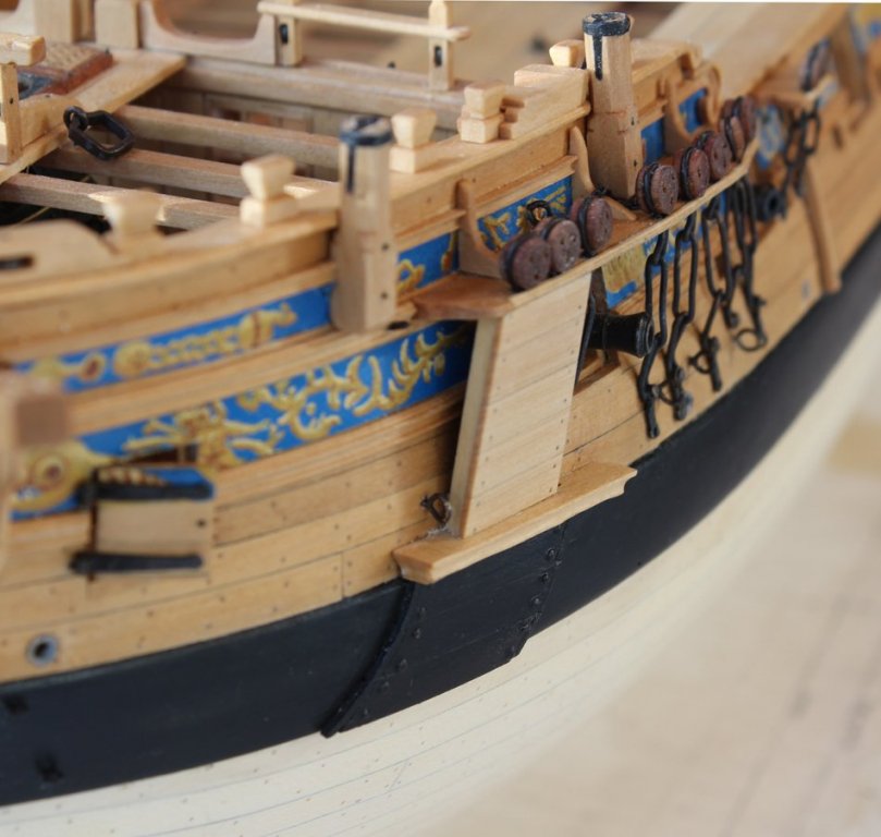
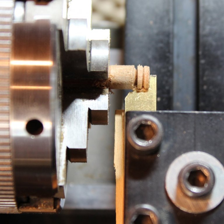
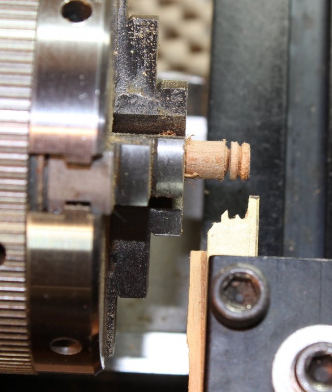
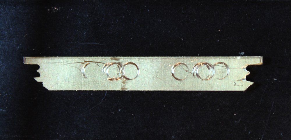
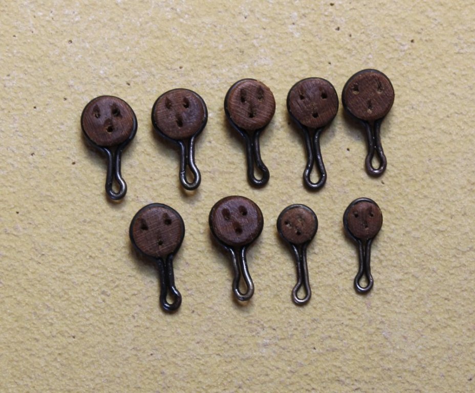
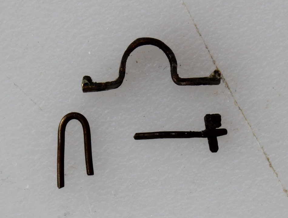
The fore channel deadeyes are next. There are seven 10" deadeyes and three 7" deadeyes. I wanted a color contrast with the rest of the hull without wanting to stain the wood so they were made of cherry. Next time I will use a finer grained wood and then stain them. These were made on the lathe using a jig. I ground the profile of each deadeye into opposite ends of a piece of sheet brass. The pictures illustrate the process. One of the keys to success is to have as little wood protruding from the chuck as possible to prevent deflection of the wood. The larger deadeyes have a four-piece chain assembly: upper link, middle link, toe (or lower) link and preventer plate. The smaller deadeyes do not have a preventer plate. The larger deadeyes have links made of 1.25" iron and the smaller deadeyes have links of 1" iron. The basis process was to form appropriate sized loops of brass wire and silver solder them. These are then squeezed around the deadeye, leaving a lower loop through which the middle link will insert. There is an inward angle on the lower loop but I did not form this until I was ready to install the entire assembly. The toe link was made similarly, using a nail instead of the deadeye to form the upper curve. The heights of the lower bolts of the toe links was taken directly from the plans. The middle link was formed and threaded through the upper and toe links. Using a heat sink on the two ends of the middle link, the middle link was also silver soldered. The preventer plates were made from brass strip. In real practice, these were forged from square bar stock. To simulate this, I engraved a line down the middle of the plate. You can just barely make this out in the plates shown below. The top of the plate has a bend in it to compensate for the thickness of the toe link. The location of the lower bolt was determined after the entire assembly was finished. The final result after blackening and installation of the channel molding and the four preventer bolts. The shankpainter chain attaches to the hull above the fore channel. It's purpose is to secure the anchors. I had some chain left over from a kit which had almost the correct size links (3/4" diameter). The spanshackle ring was made from brass rod. The curved section was shaped first. Then the rod was bend to form the side arms. Finally, the length of the lower arms was determined and the ring was soldered closed after the ring bolt had been threaded on to the ring. I chose not to add deck planking under the ring so it is installed elevated above the beam the thickness of the deck planking.


-
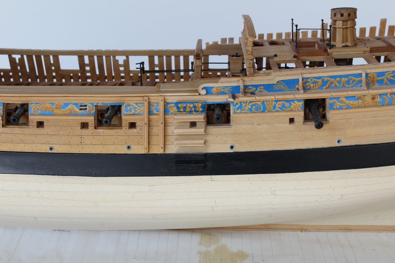
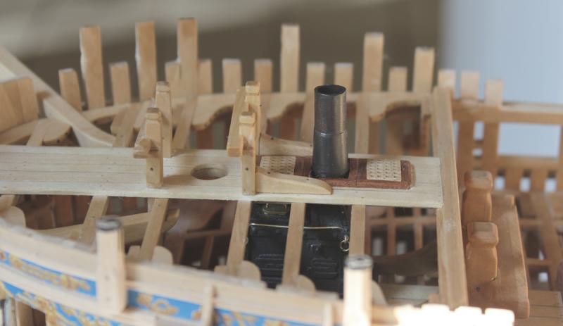
Not all Swan class ships had the style of chimney shown by Greg. Both Fly and Atalanta had a straight flue as seen below.
-
Patrick, your wife is 100% correct. What you are describing is having several incomplete projects. True multitasking is when you are working on a build while simultaneously running the washing machine, prepping dinner and picking up after the man of the house!
-
Beautiful work, Mike. Cannot wait to see more.
-
Le Soleil Royal by Nek0 - 1/72 - Marc Yeu
tlevine replied to Nek0's topic in - Build logs for subjects built 1501 - 1750
Beautiful job on the planking.- 208 replies
-
- 3
-

-
- le soleil royal
- 104 guns
- (and 2 more)
-
Great to see you back at work. Getting those counter frames correct was one of the more difficult parts of the hull construction.
-
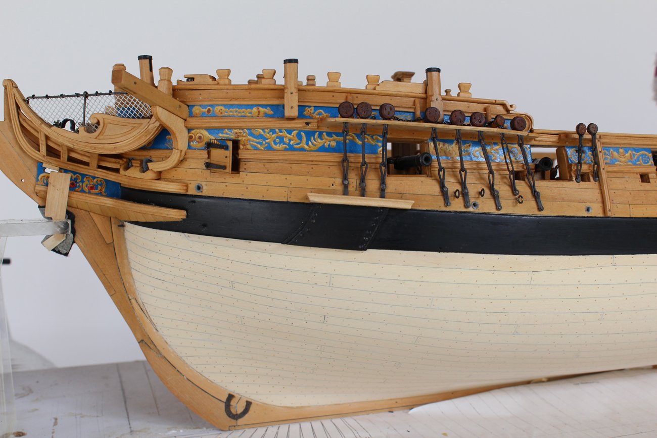
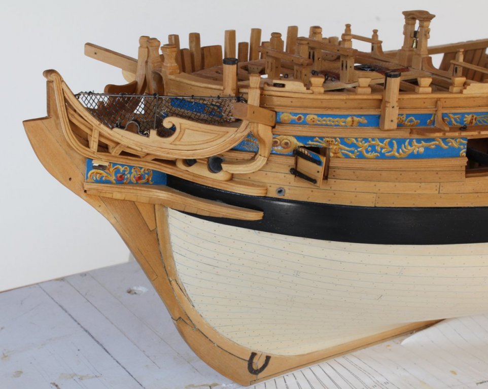
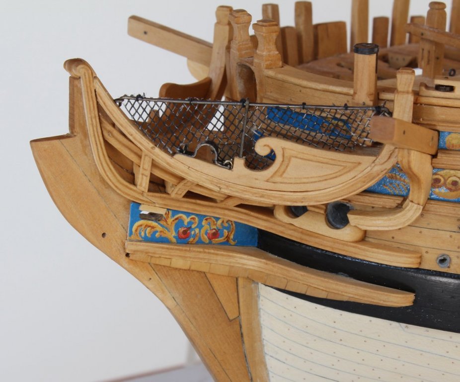
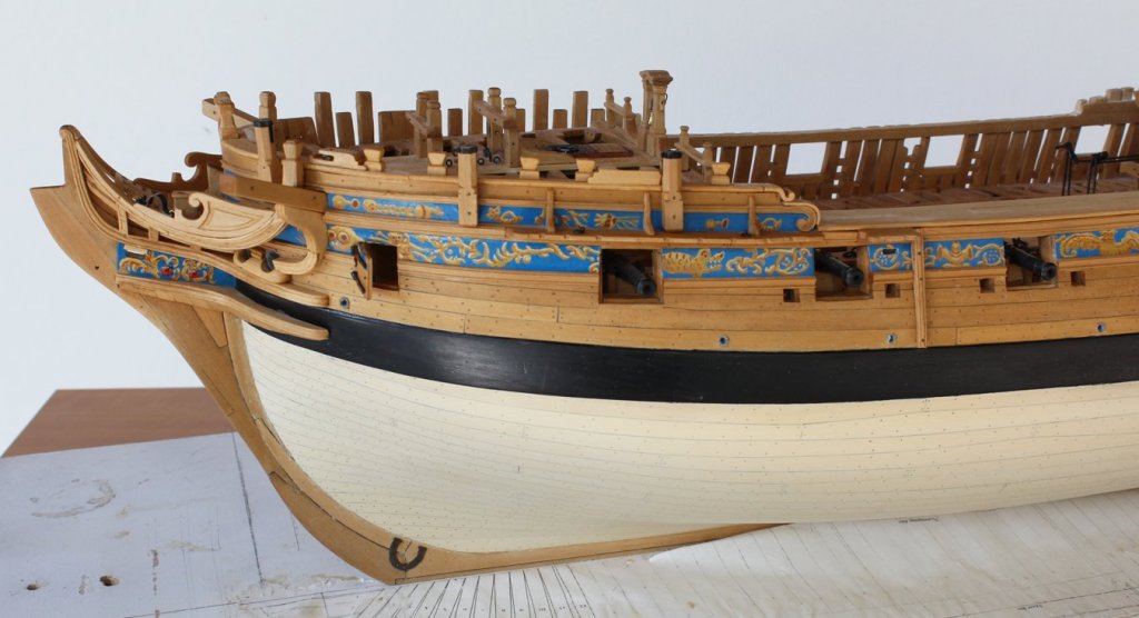
The berthing rail attaches to the main rail with two eyebolts. A stanchion is threaded onto the rail before it is inserted into the eyebolts. This is secured to the false rail. Netting extends from the berthing rail down to the main and false rails, leaving an opening for the boomkin. Conceptually, this is pretty straight forward. However... Tulle is netting used to make veils and formal wear. The netting openings are 0.05" which is 2.5" at this scale. The netting opening needs to be 3-4". There is no fabric manufactured that fits the required specifications. (Believe me, I looked!) Other options I looked at were hand-tying the netting or finding a non-fabric substitute. Hand-tying was not going to happen. The closest I could get was screening material. This comes in two basic types, metal and nylon. I found an old screen door and helped myself to a piece of the screening. The net opening was 3 1/2". I attached this to the berthing rail with multiple knots. Still not sure if I like the looks of it, since the netting should be natural and not dark, but for the time being it is the best I can do.
-
Thanks, Druxey. I start by brushing it on and then wipe off the excess after five minutes.
-
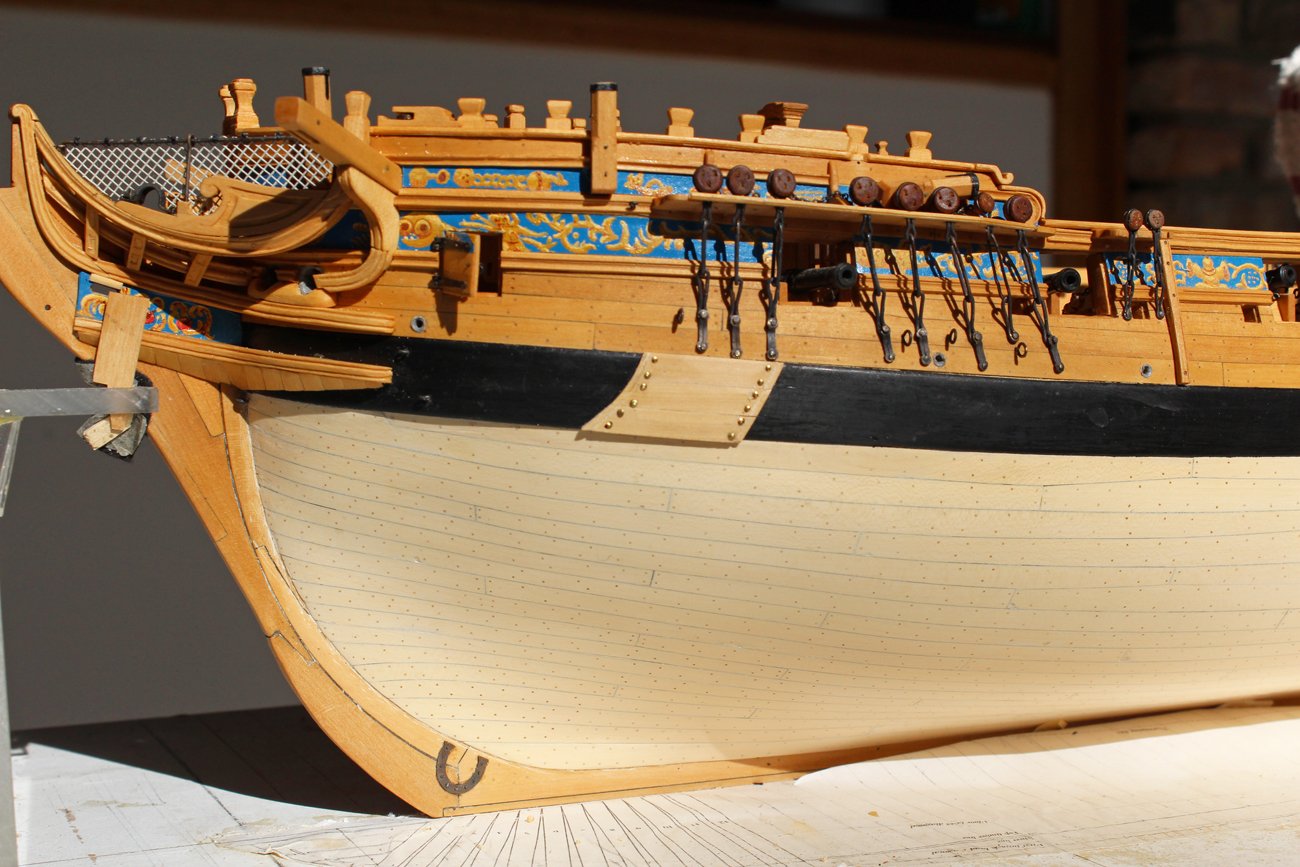
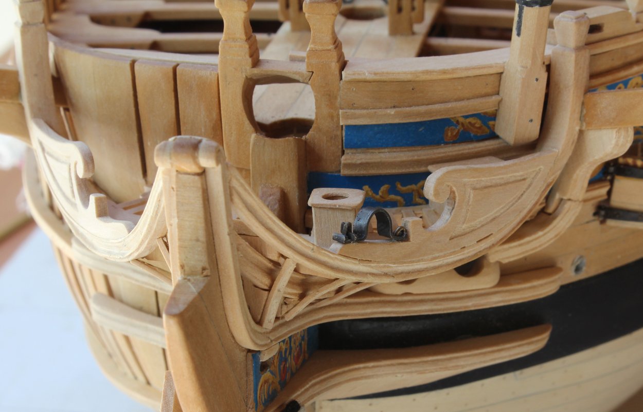
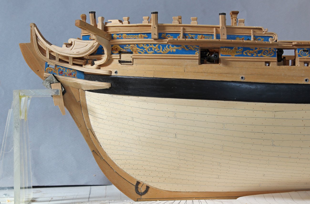
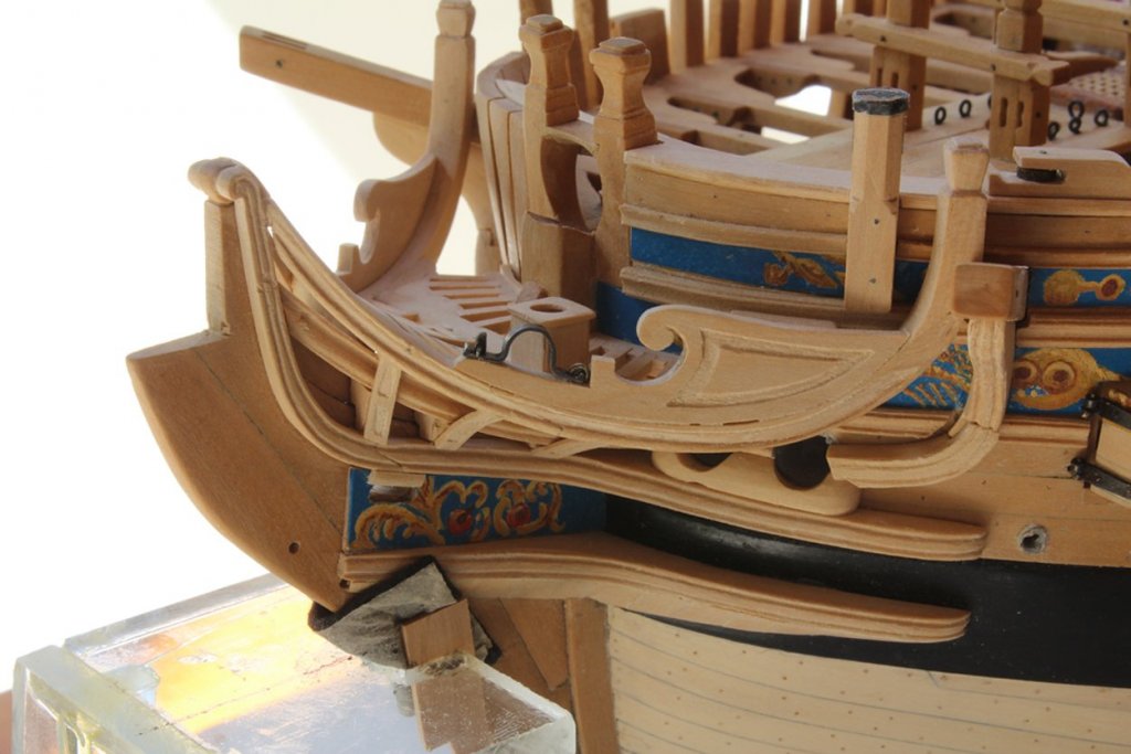
The cat block for the falls has been fabricated and installed. This is a snatch block, meaning that one end of the slot is left open. The aft end of the block is mortised around a timberhead. I have also installed the fish davit cleat with a slot inboard and a straight appearance when viewed from the side. This is also mortised around timberheads. The boomkin capsquare is located on top of the false rail. It is secured to the rail with a hinge aft and an eyebolt and key fore. It looks better in person than the photos suggest! I have now reached a milestone: the woodwork has been completed on the front half of the ship. For both protection and appearance I applied the initial coat of finish (Watco's Danish Wood Oil). What a difference the finish makes. Now one can see all those treenails that were installed a long, long time ago. Unfortunately, it also shows up the flaws. the last photo shows the difference the finish gives. The aft half of the ship does not have finish applied.

-
Thanks Tom. That's the problem when you do not know the correct name for things...you can't look it up in the index! Druxey, I am leaning to your interpretation and will score the cleat inboard.
-
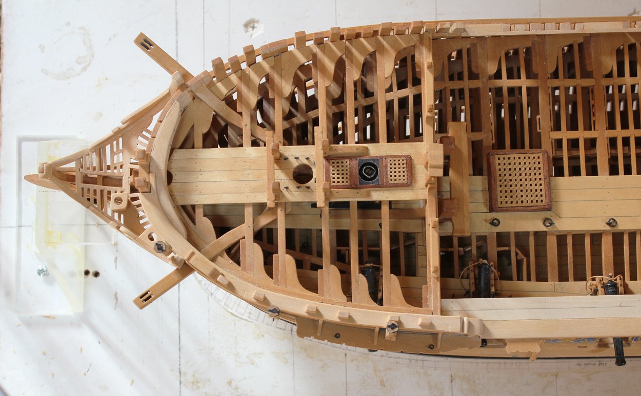
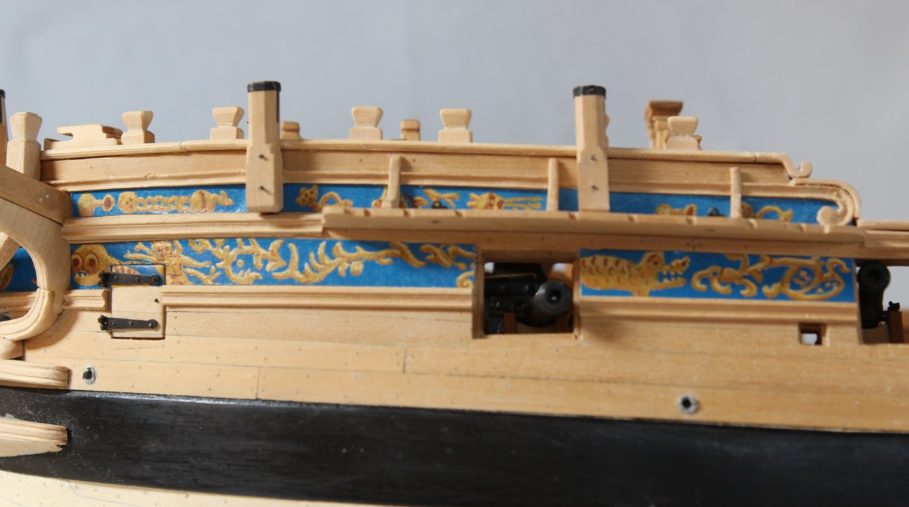
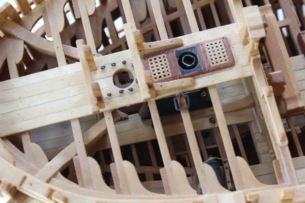
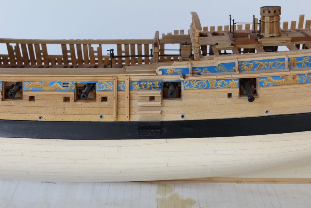
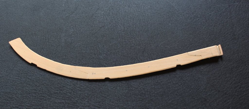
In the meantime I have made the plankshear. This is made of three pieces of plank, scarfed together. There are mortises for the three gun supports and the edge has a decorative molding on the inside and outside faces. In order to get the molding to flow across the joints, I make and temporarily installed the planksheer. Next I popped it off the timbers, leaving the joints intact. I was now able to cut the molding in one sweep with the scraper. The photo shows the three pieces glued together and removed from the model. This actually is a discarded piece as I forgot to extend it to the midline and I did not like the shape of the hance. Once this was glued into place, I cut mortises for the timberheads and installed them.

-
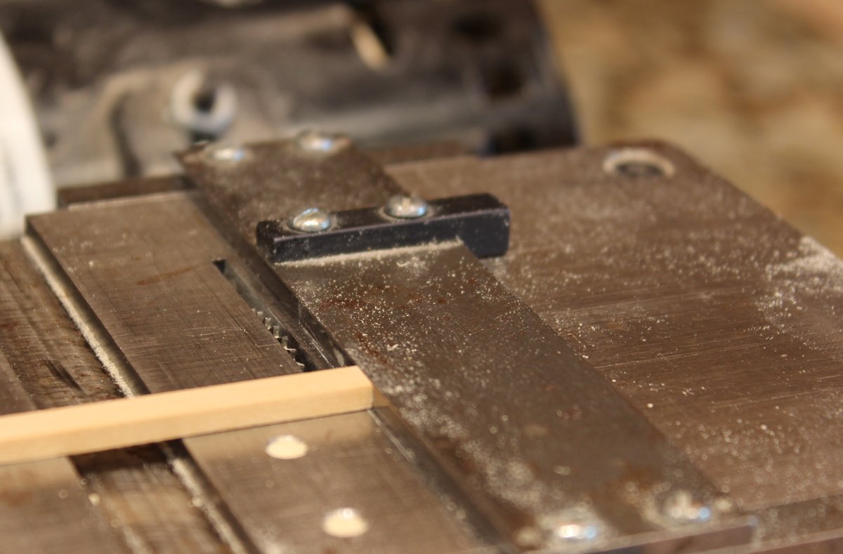
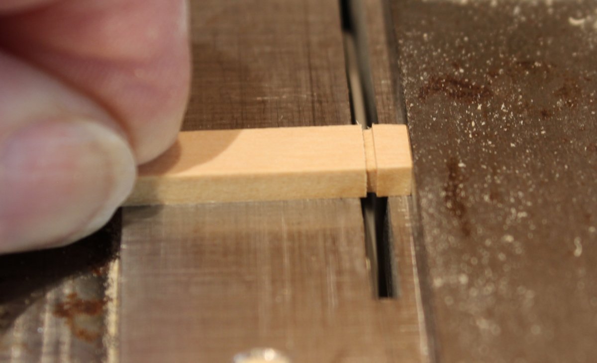
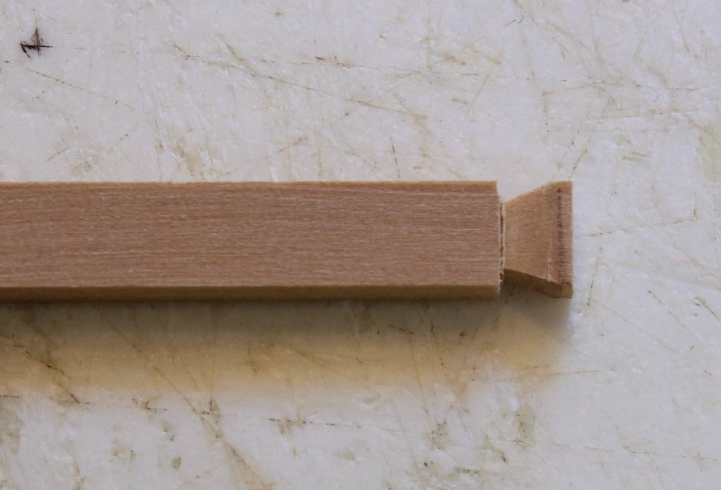
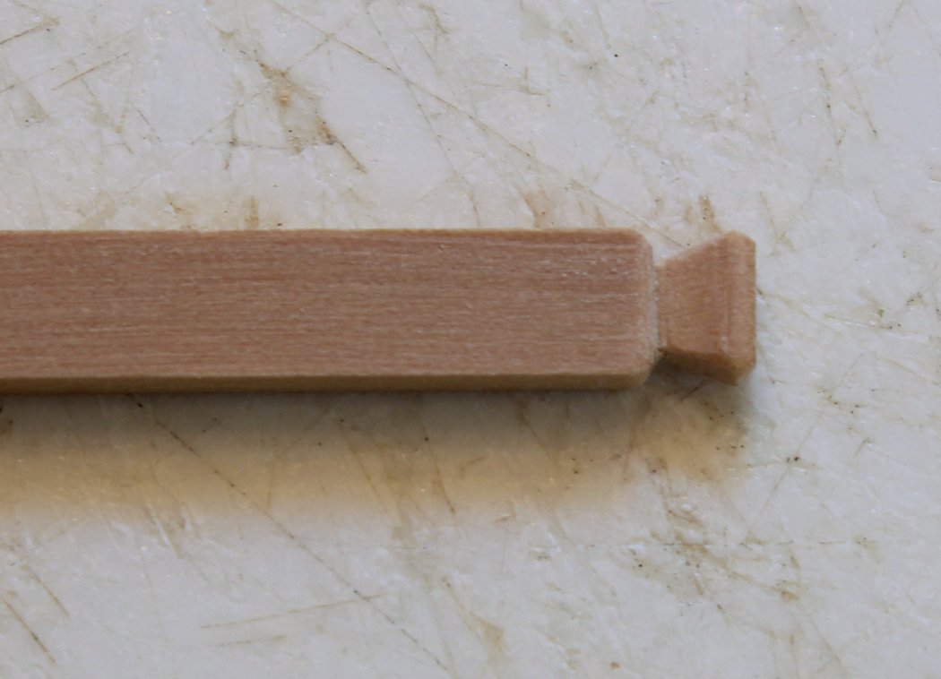
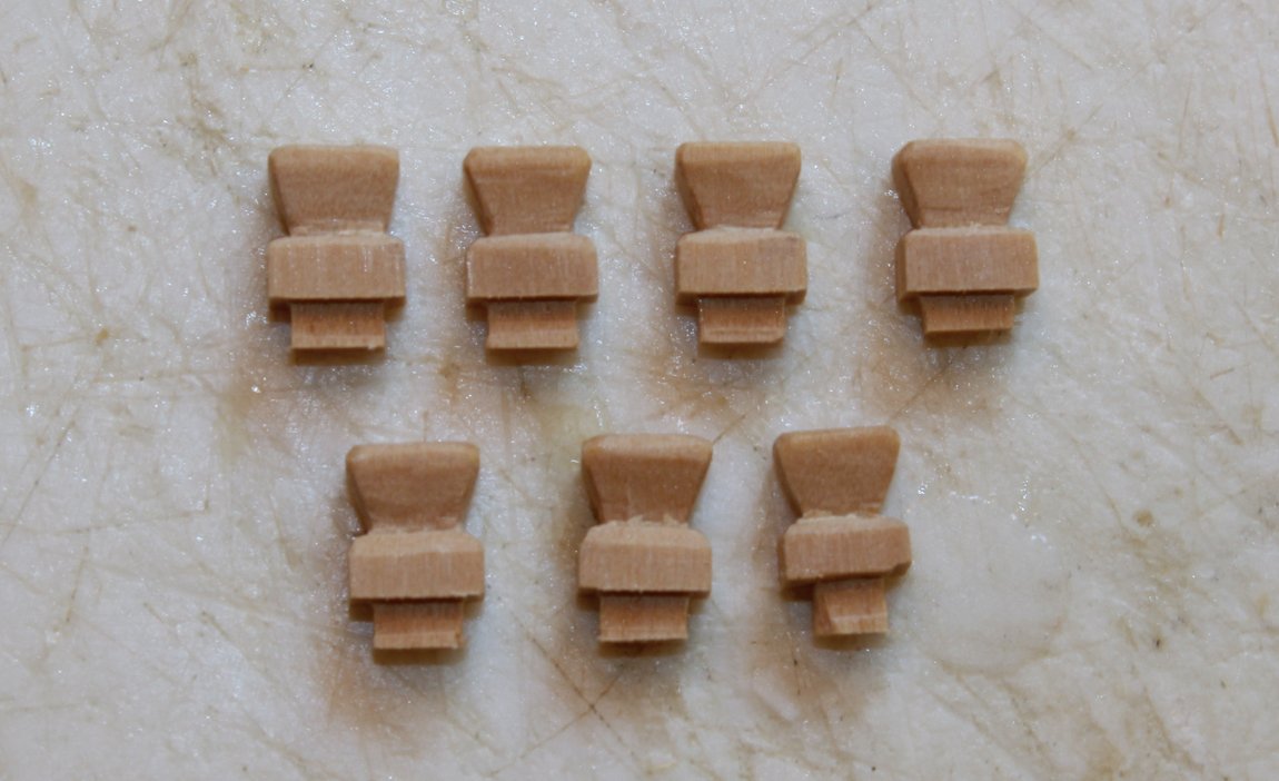
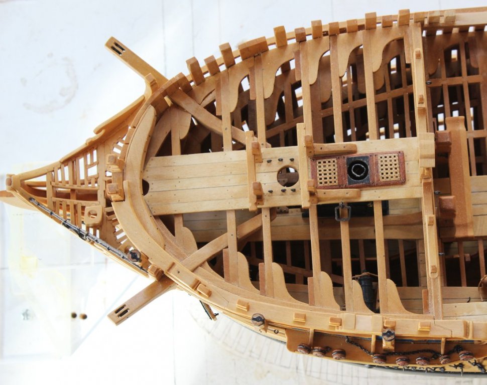
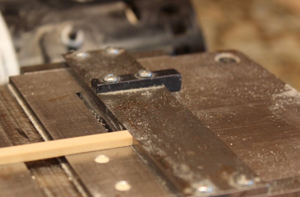
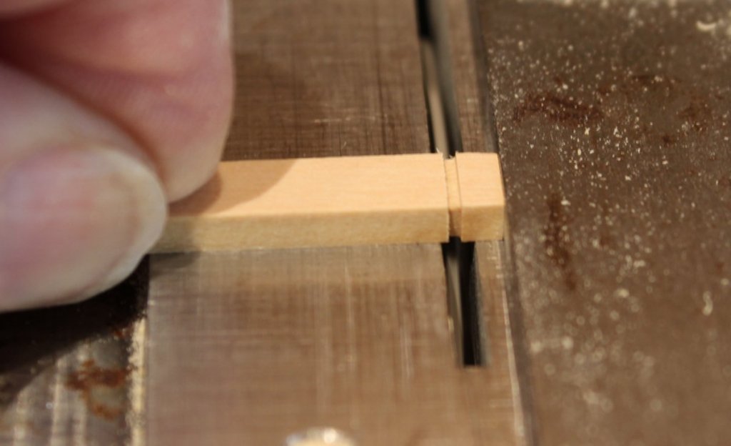
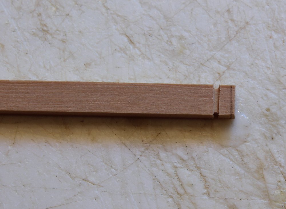
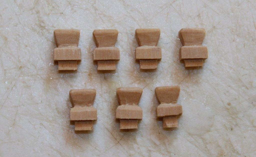
Although a little out of sequence, I decided to do something "simple" today and make the timberheads. I cut off the timberheads at the level of the plankshear on the port side because I knew I would never do an adequate job of shaping them in situ. The false timberheads will have a stem to pass through a slot in the plankshear. Here is how I made them. First thing was to dimension the appropriate size lumber. On my table saw I set the fence and the blade to delineate throat of the timberhead. I made this a little shallow to allow for final shaping with the chisel. I drew a pencil line a little below the top of the timberhead. This marks the top of the chisel cut. Next I cut down from that line into the notch formed by the saw. The top of the timberhead was beveled as was the area below the throat. Finally I made a tenon and cut the piece to final length. There are six timberheads on Atalanta.


-
Danny and Wayne, thanks for you input. Danny, the same item on the Fly looks just like yours. On Atalanta's plan it is solid across the top, instead of having "horns", thus my confusion. Time to do a little more research.
-
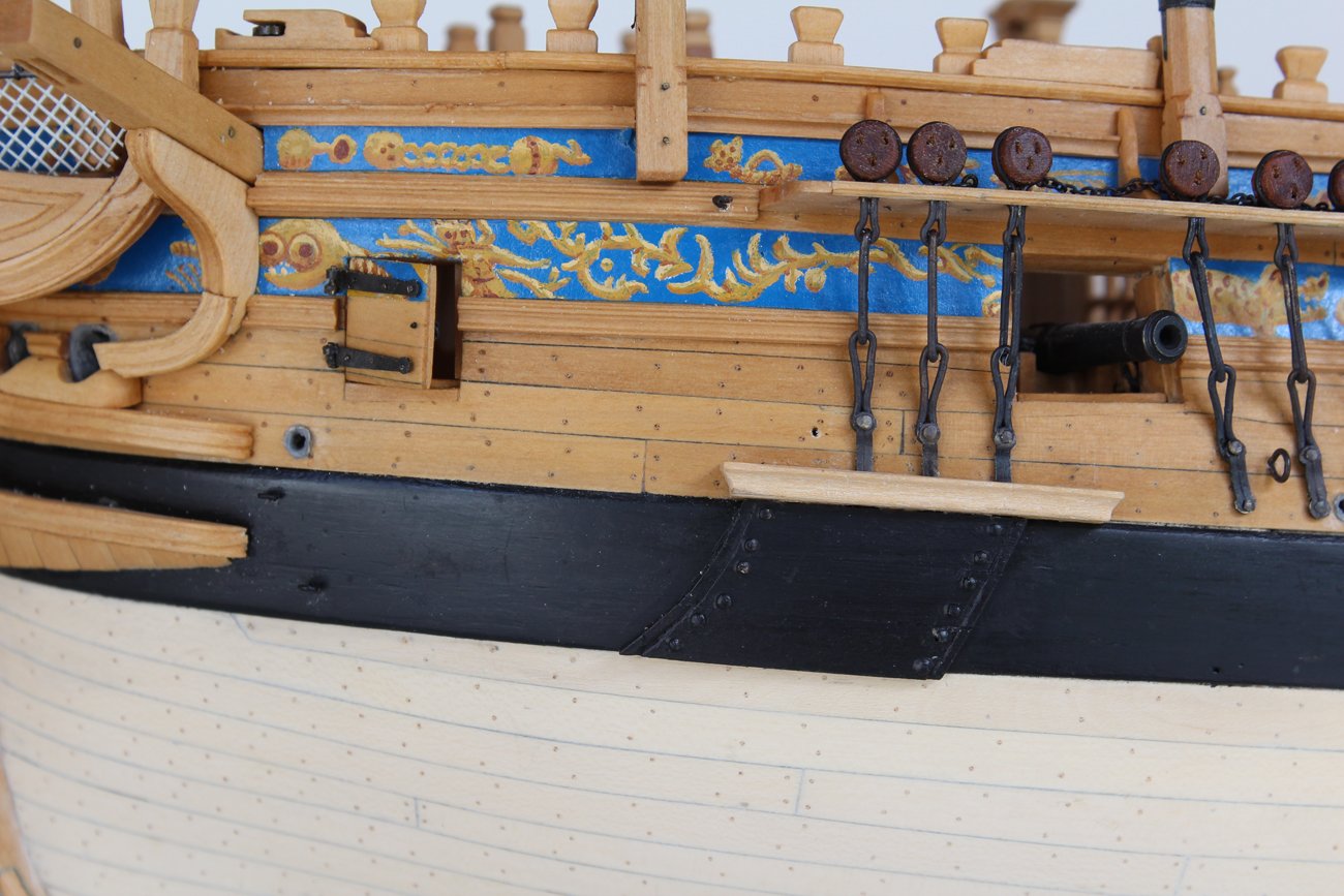
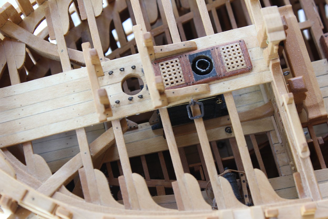
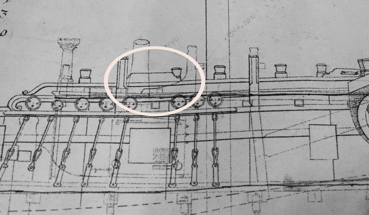
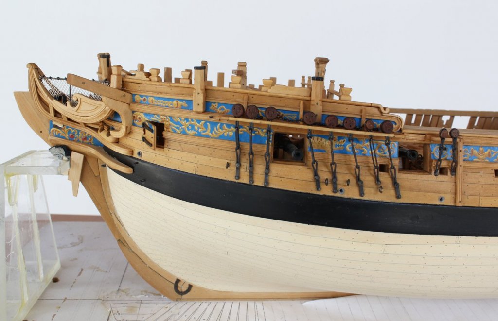
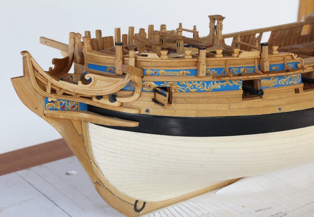
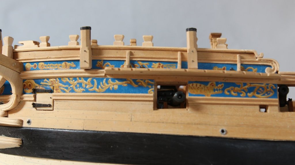
Thanks everybody for the nice comments and the Likes. I have run into a bit of a quandary. I have been working on the fore timber heads (more on that in a later posting). While looking at the plans I noticed a structure on the rail at the level of the fore shrouds. In the picture it is circled. I looked at the plans for Fly and it shows a similar object, although a bit more decorative than on Atalanta. If anyone knows what this is I would appreciate your input.

-
Also turn the piece around every other pass so that you compensate for any angulation while feeding the wood into the sander. I also sand down both faces unless one of the faces has been planed smooth.