HOLIDAY DONATION DRIVE - SUPPORT MSW - DO YOUR PART TO KEEP THIS GREAT FORUM GOING! (Only 13 donations so far - C'mon guys!)
×

tlevine
-
Posts
2,032 -
Joined
-
Last visited
Content Type
Profiles
Forums
Gallery
Events
Everything posted by tlevine
-
 For a test run they look great. I take it the capstan is double with one assembly on top of the other?
- 525 replies
-
- 3
-

-
- anchor hoy
- hoy
- (and 1 more)
-
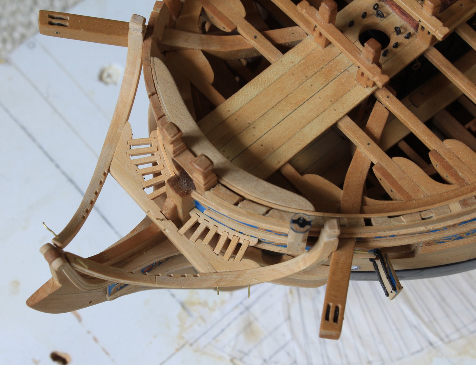
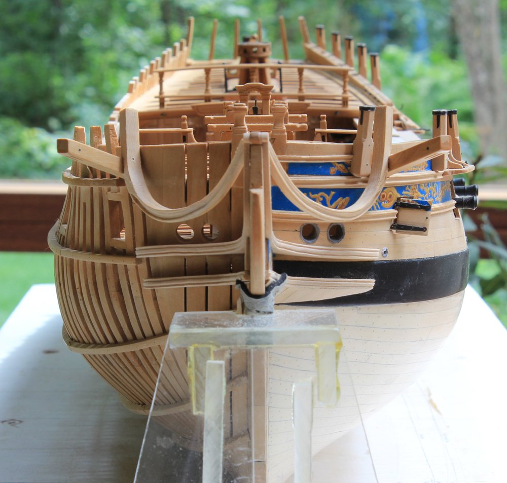
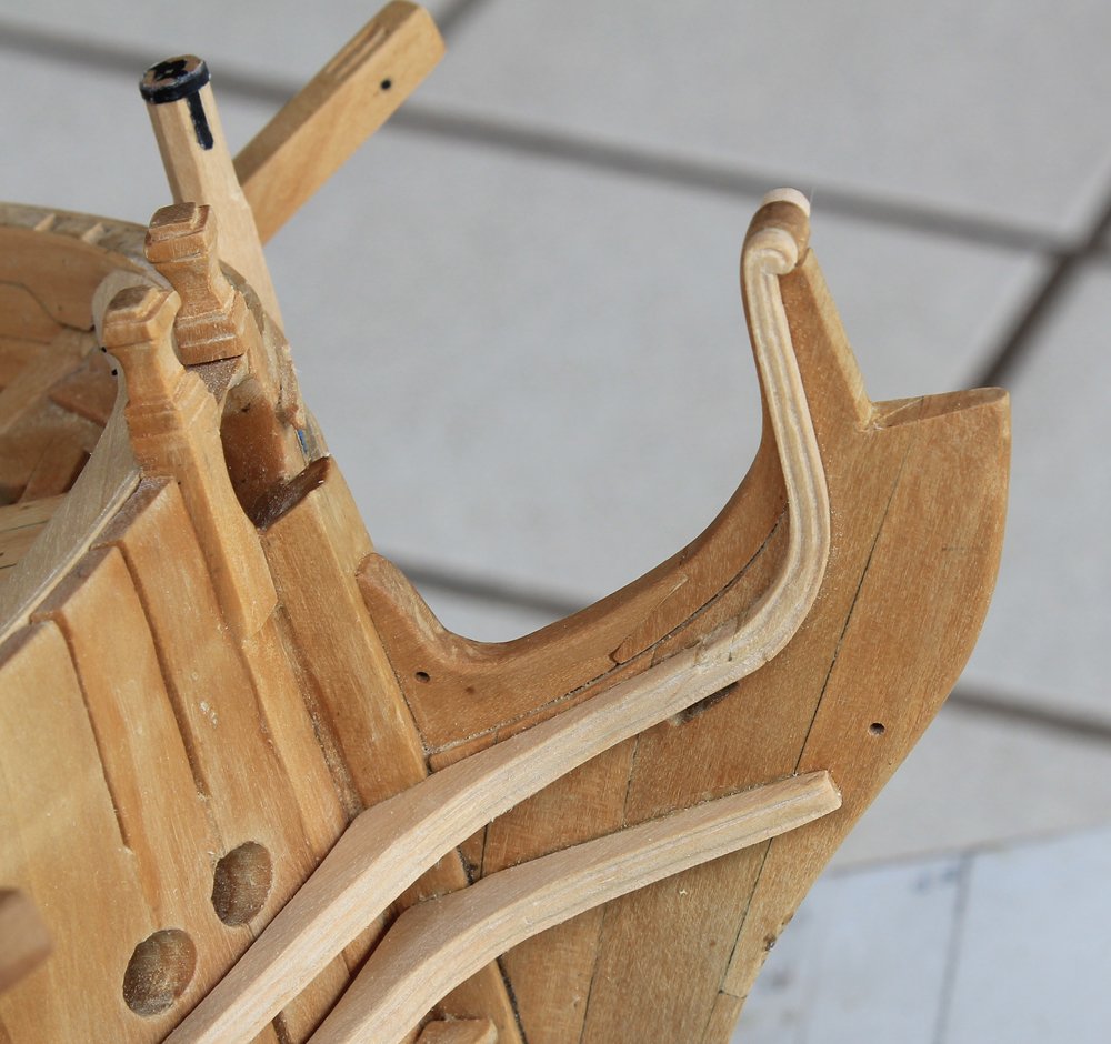
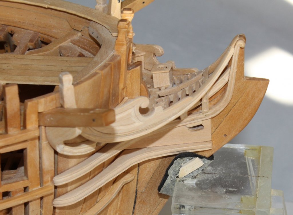
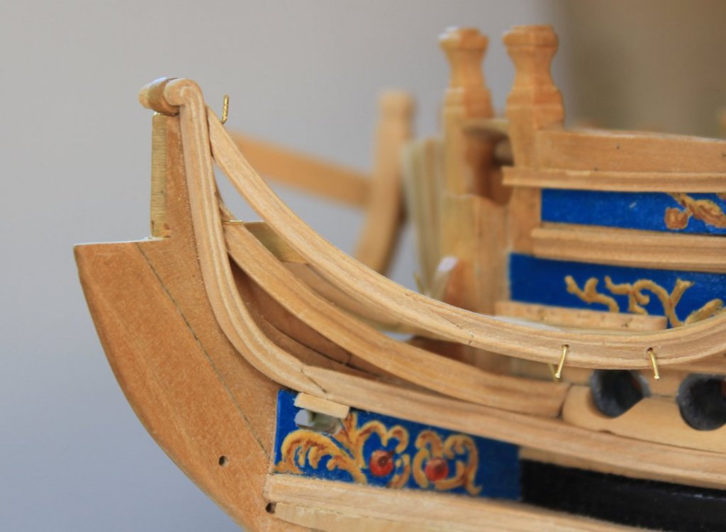
The next things to tackle are the cathead supporter and eking rail. Unfortunately, I left my camera at work so all I have are completed photos, not work in progress. I will try and describe the process as well as I can. The cathead supporter is just that, a knee under the cathead which then curves and blends in the lower rail via an intermediary eking rail. My first step was to lightly draw the curve of the supporter/rail assembly onto the starboard (unplanked) side of the hull. I made a template of this shape to duplicate the curve on the port side. Next was to make a template of the angle between the hull and the inferior surface of the cathead. Both templates were transferred onto an over-sized block of wood and the excess wood was sanded away with a Dremel and sanding sticks. This is a lot harder than it sounds since the supporter must snug up against the hull as it curves inward anteriorly and outwards inferiorly. I used the same scraper that was used on the lower rail to carve the decoration into the face of the supporter and, eventually, the eking rail. Once this had been done, a scarf was cut into the lower aspect of the supporter. The eking rail was also cut overly thick and offered up to the hull for final shaping. On Atalanta, the eking rail does not extend above the top of the hawse hole and so is actually one longer piece and two short ones. I presume this is just for visual effect as there is no structural advantage to these short segments. The other end of the scarf was cut into the eking rail before the final shaping to ensure a tight fit. The port side was done in similar fashion, using the curve template from the starboard side to get the curve correct. I removed the decorative rails to facilitate fabrication of the pieces and then replaced them after the supporter/rail were secured. Like I did with the the cheeks, I offset the cathead supporter and rail a plank's thickness from the hull on the starboard side. The gap between the false rail and the main rail will be filled in with sawdust. Visually, I thought it more important to have the panel edging the same thickness all around. Now on to something a little less complicated. I have decided that Atalanta had four seats of ease. One is out on the carlings and the other is tucked in behind the false rail. I did not make the ones for the starboard side so that the joinery at the base of the seat could be seen. As one can see in the first photo, there is a straight shot down through the hole without (theoretically) soiling the rails and cheeks.

-
Something else to consider for the library is the CD collections of Ships in Scale and Model Ship Builder. The older magazines would have serialized articles, some spanning well over a year detailing construction of specific ships or kits. This was the era before internet so these magazines were the ultimate build-logs of their time. For example, the SIS series on Mantua's 1:98 Victory was detailed enough to be published later as a ring-fold-binder book and (although not completely accurate) was instrumental in my kit bash of that kit 20 years ago.
-
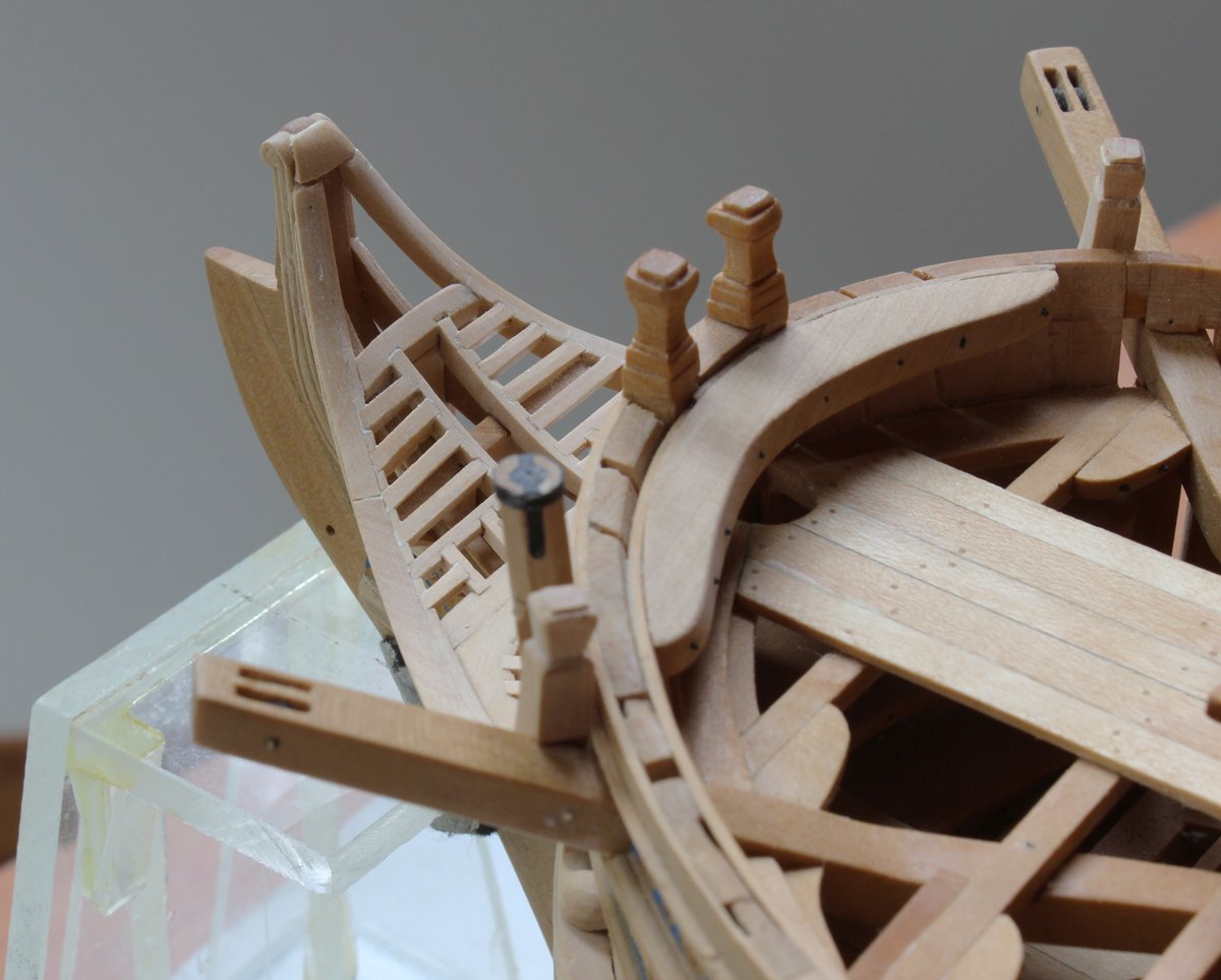
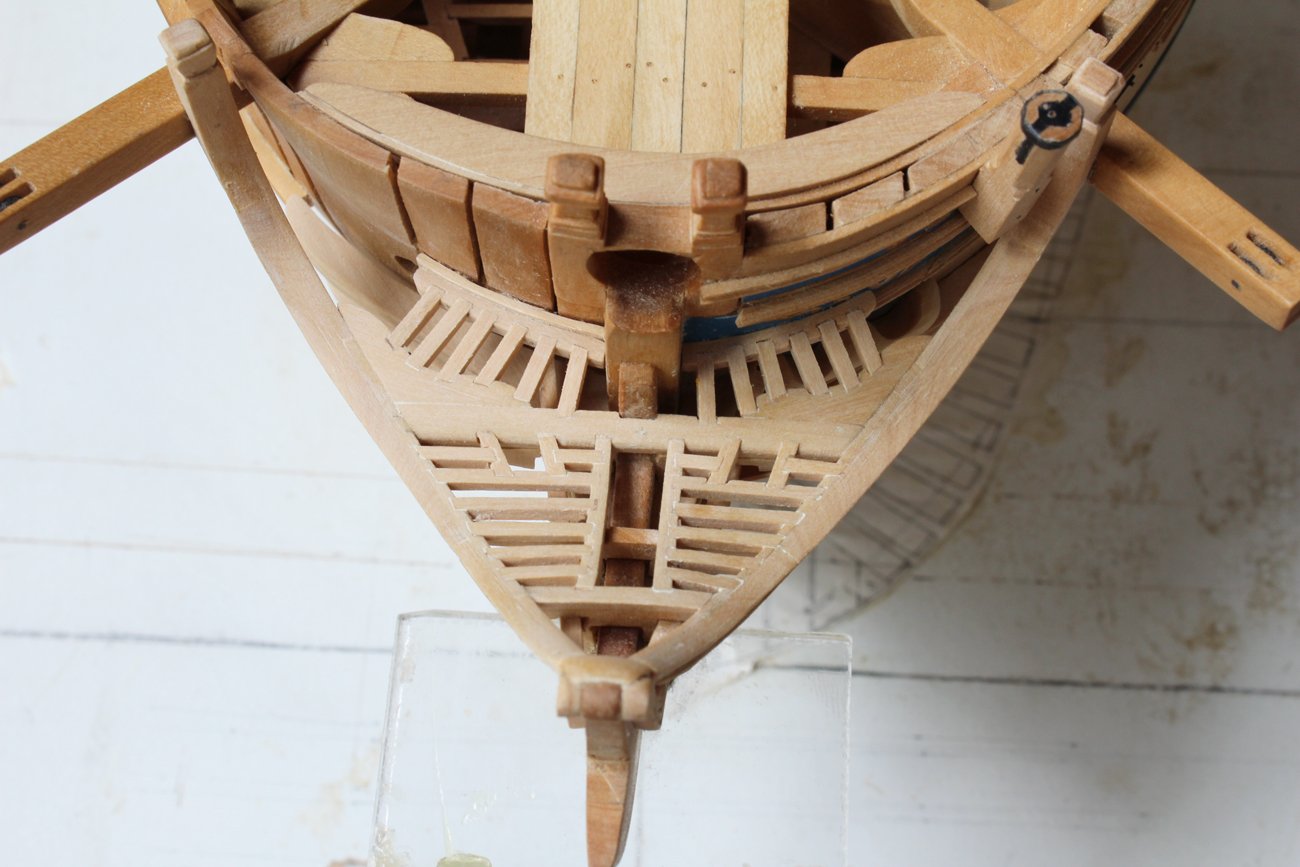
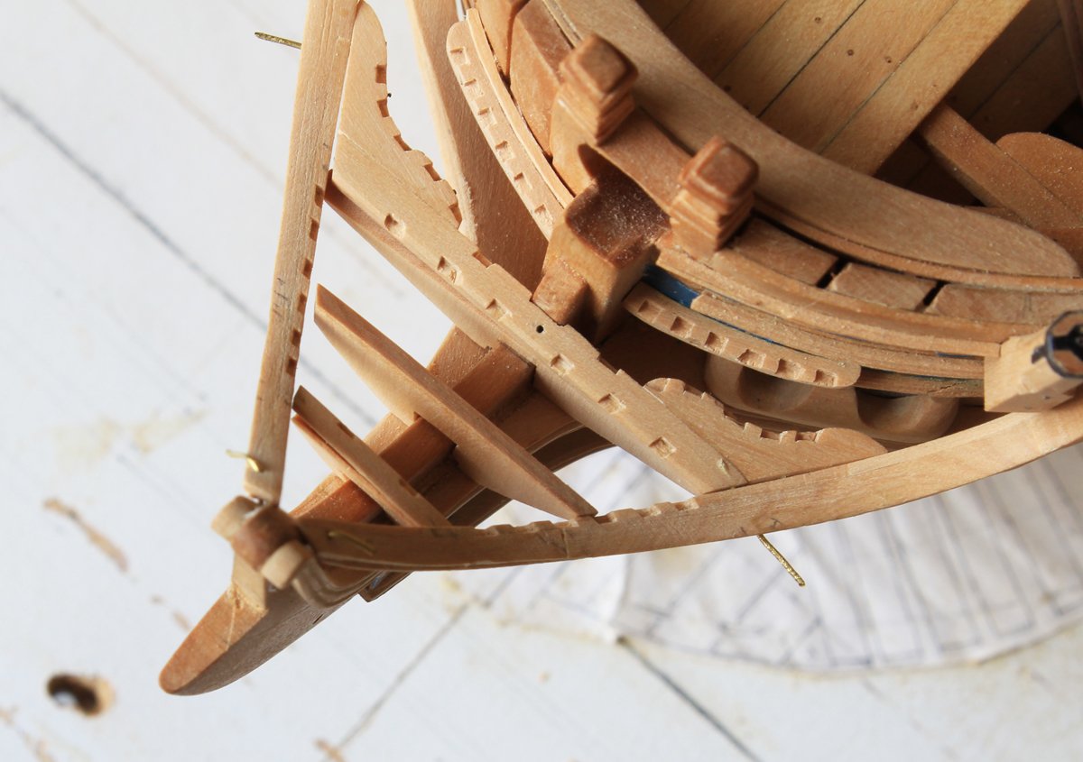
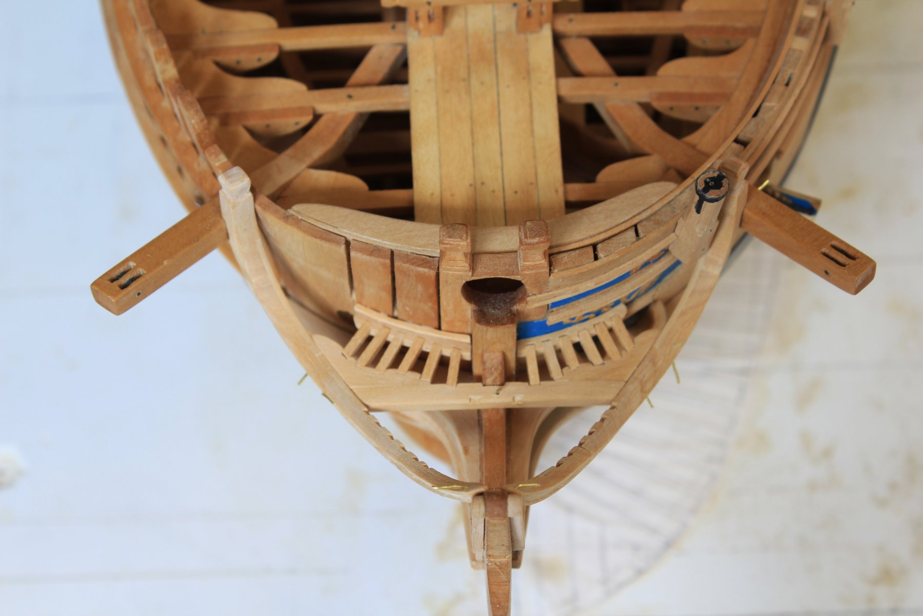
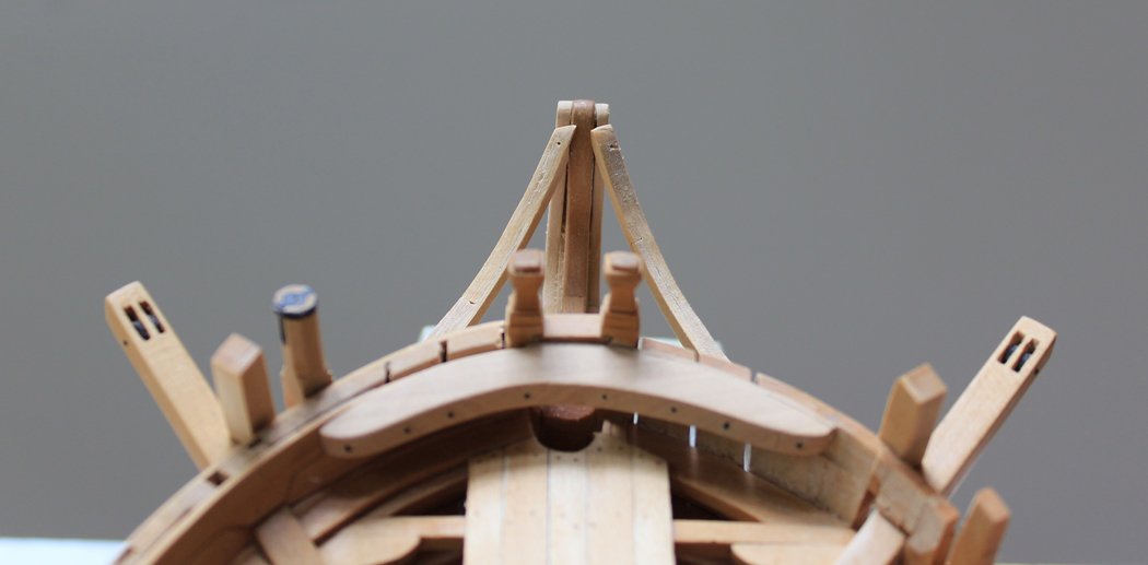
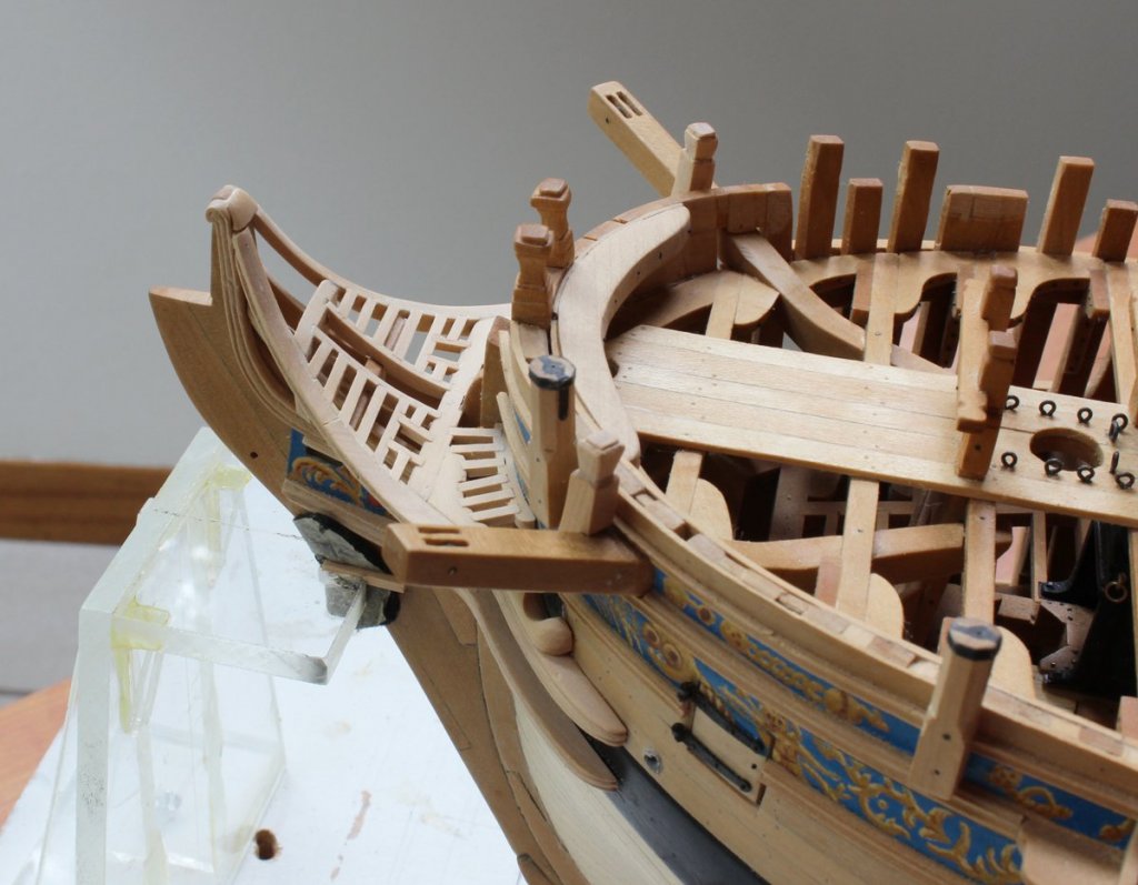
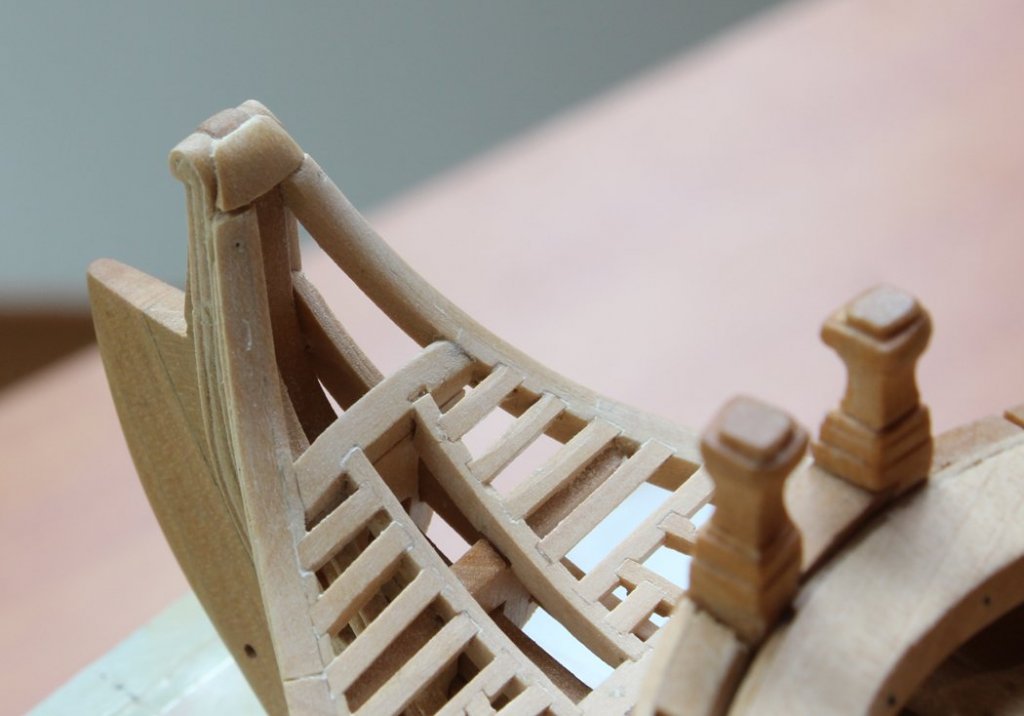
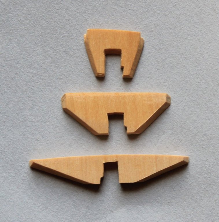
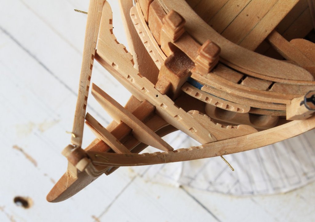
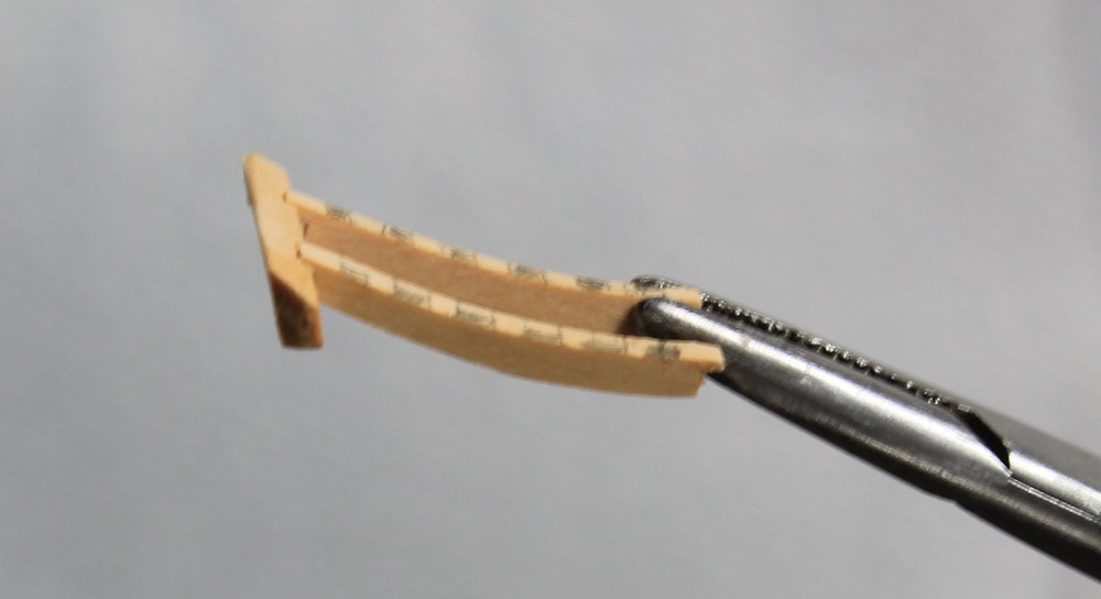
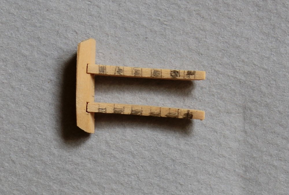
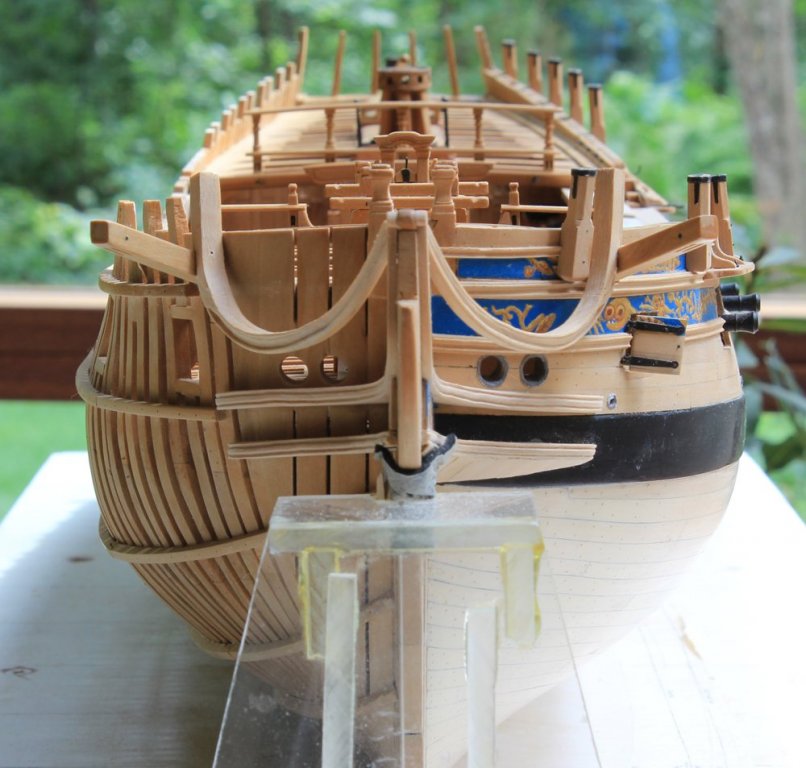
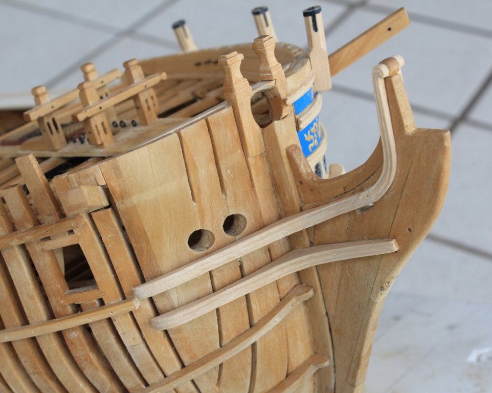
I have finally had some time to devote to the workshop. Last weekend was spent chasing the eclipse in Kentucky and testing (tasting) the Bourbon Trail. Time very well spent. After all...it was educational! Next up were the head timbers. Atalanta had three; some of the Swan class ships had four. These were a royal pain-in-the-you-know-where to fabricate. They have to fit the stem assembly as well as meet the main rail. They also have the same camber as the grating. The notches at the base of the timbers are because the various components of the stem assembly did not mate perfectly way back when. I decided I would to more damage than it was worth to make it better and so modified the head timbers to fit instead. In the second picture, one can see how the third head timber (the largest) fits under the head beam. Each beam is a different thickness, with the fore beam being the thinnest. This is most readily seen in the third picture. These photos are all taken while the timbers were being shaped and so do not fit correctly at this stage. The next step is to cut an opening in the head timbers to accommodate the middle rail. This was simply a matter of trial and error, many hours and even many more expletive deleted's. As I mentioned in a previous post, in the first timber the slot for the middle rail needed to be cut from the bottom rather than from the outer edge. The next item was the head saddle which extends from the fore ends of the main rail to the tip of the stem. I started with an oversize piece of wood and carved the underside to fit first. Then I cut the upper face and finally finished it on the model. Now everything is ready for assembly. The covering boards are 1" thick and cover the outer edge of the head timbers. They have two panels carved into them. Looking at the next photo I now see that the third timber needs to be unglued and re-positioned to make it perpendicular to the water line. Hopefully I can accomplish that without damaging anything else. The holes from the brass pins also need filling.


-
Welcome to MSW, Piotr. What other models have you built in the past?
-
Thanks everyone for your comments and likes. Elijah, the notches for the gratings are started with a razor blade saw. Ask Kurt to show it to you at the meeting next week. Then I used a combination of #11 blade scalpel and 2 mm chisels to deepen them and square them up. Maury, you are looking at this waaay to closely if you are checking out the number of holes for seats of ease. Knowing you had the same problem Danny makes me feel more comfortable. I also noticed you had the same situation with the second head timber that I am experiencing with the notch directed down instead of outboard. So far, those head timbers have taken 15 hours to get right and I would expect another 10+ to mate them to the middle rail. I will post pictures when they are finished up.
-
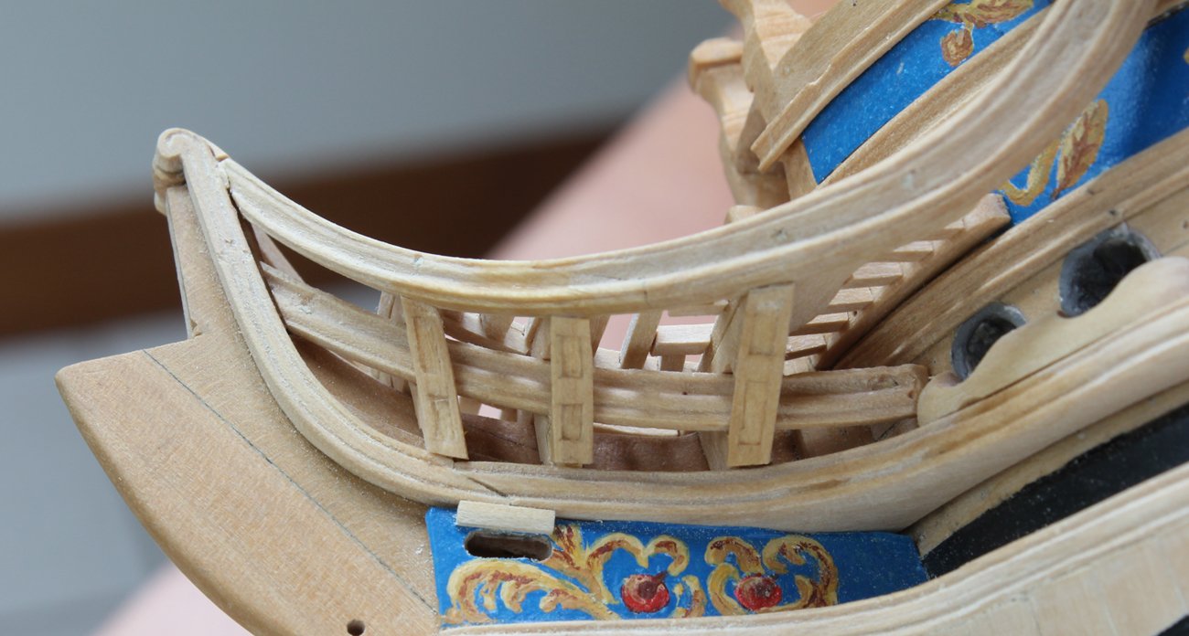
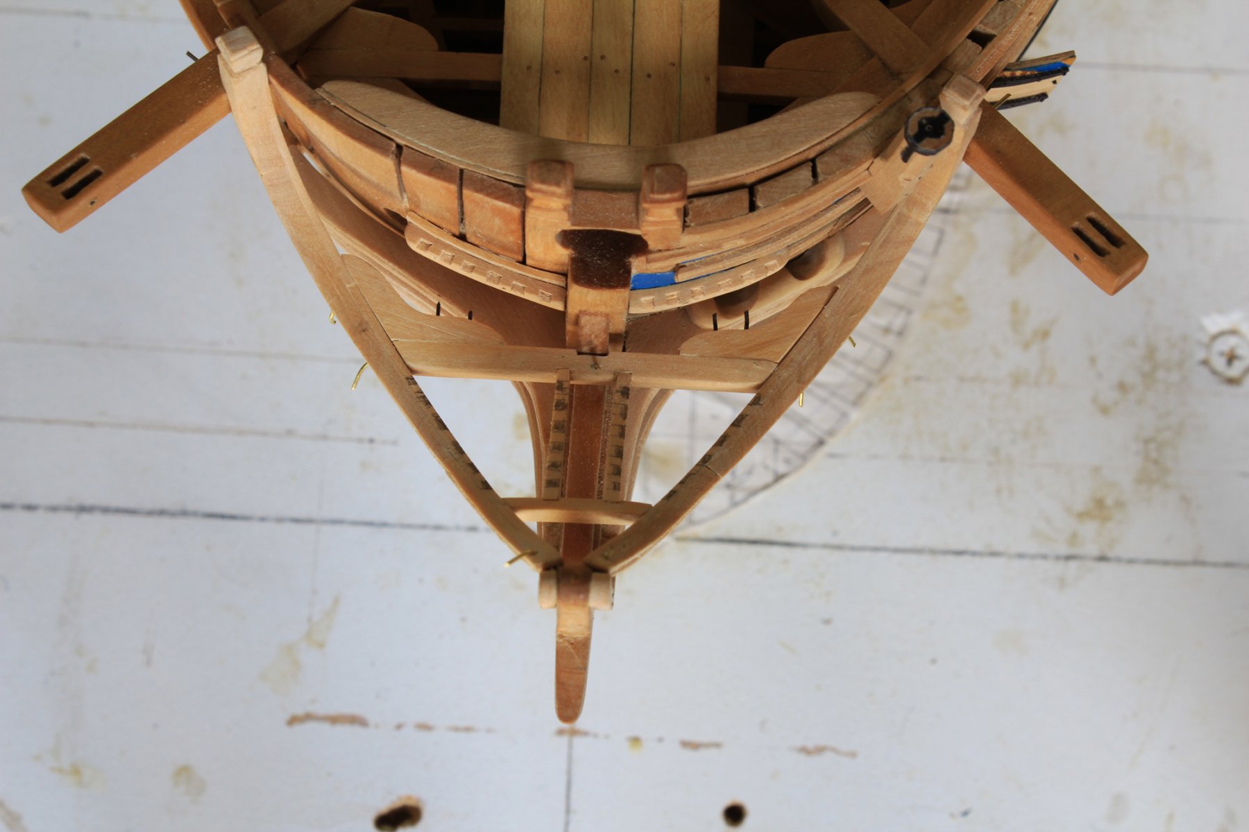
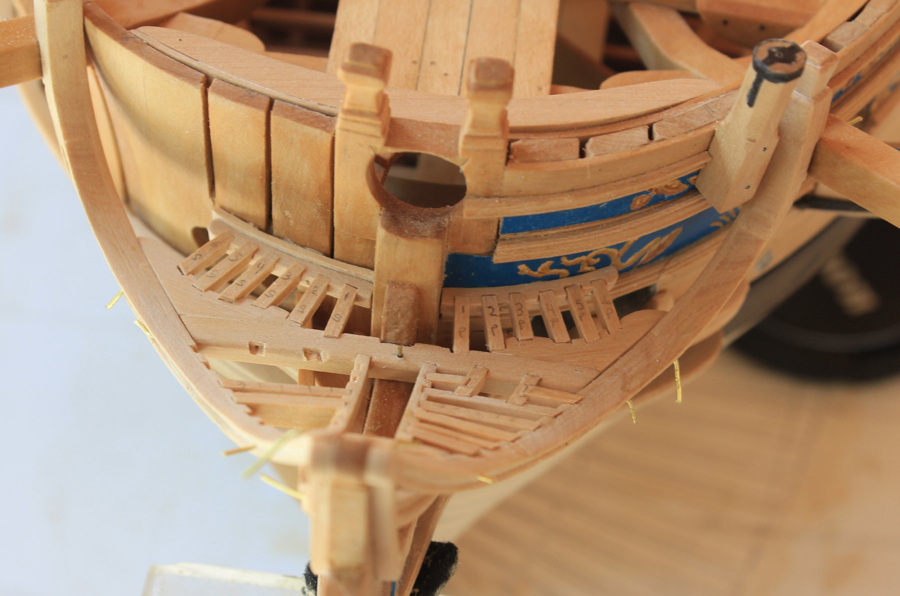
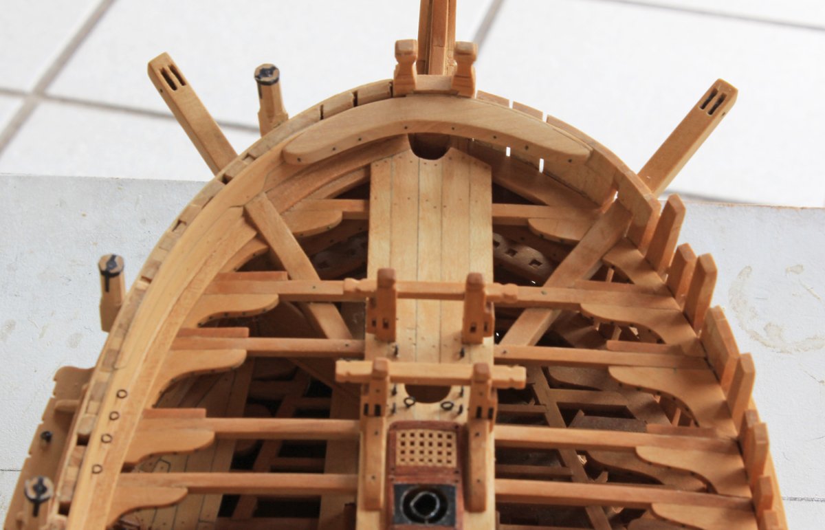
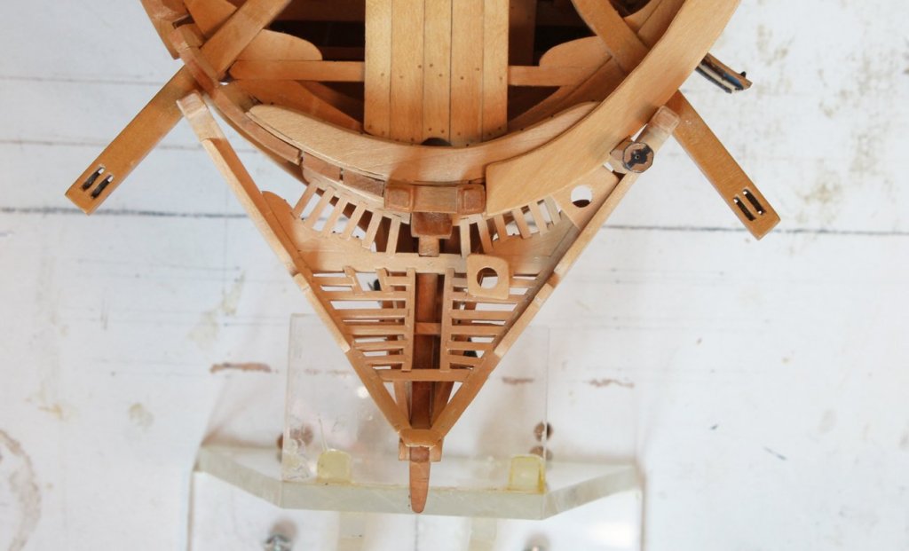
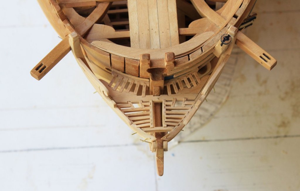
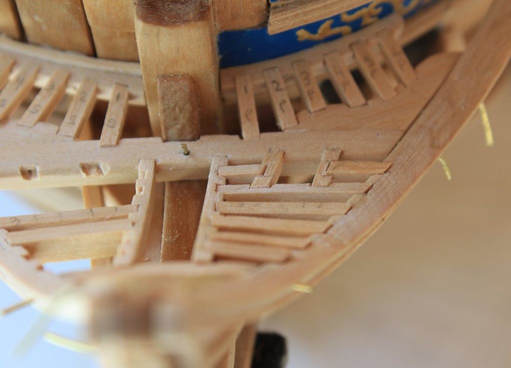
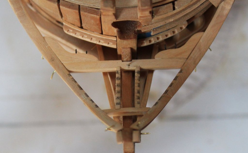
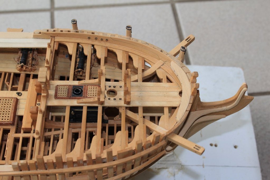
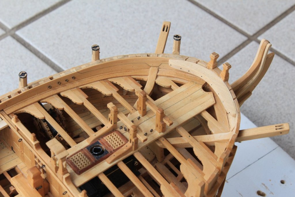
Work continues with the fabrication of the lower rail. Compared to the main rail, this is duck soup. Only one size of profile cutter is necessary. The shape is determined by the same expansion drawing that was done with the main rail. In the pictures you can see pin holes for securing it in place. The head beam and cross piece were removed to facilitate fitting. The first photo shows the mortices marked on the various structures. I started with the fan-shaped grating behind the head beam. As Atalanta had four seats of ease, only six ledges were required. If there were only two seats of ease, then eight ledges were installed. Each piece was marked since they would be stored away until the entire head was completed (or for photos). This provides, along with the pins, a lot of structural stability for the head assembly. At this point, the rest of the ledges and the small carlings for the seats of ease were constructed. The false rail is a decorative board located on top of the main rail. It screens the aft seats of ease, so it must have been the preferred location for doing one's duty. The pictures show it set on top of the mail rail but it has not been finish sanded at this point.


-
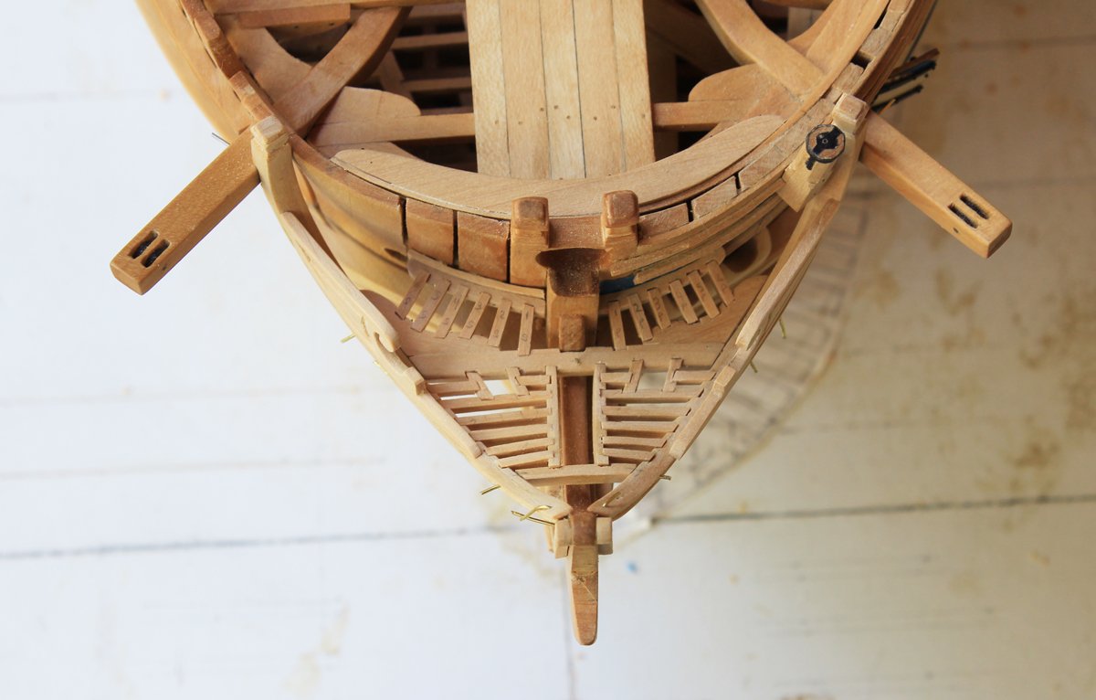
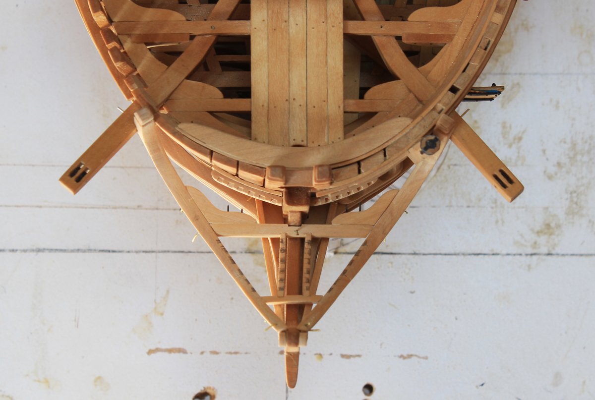
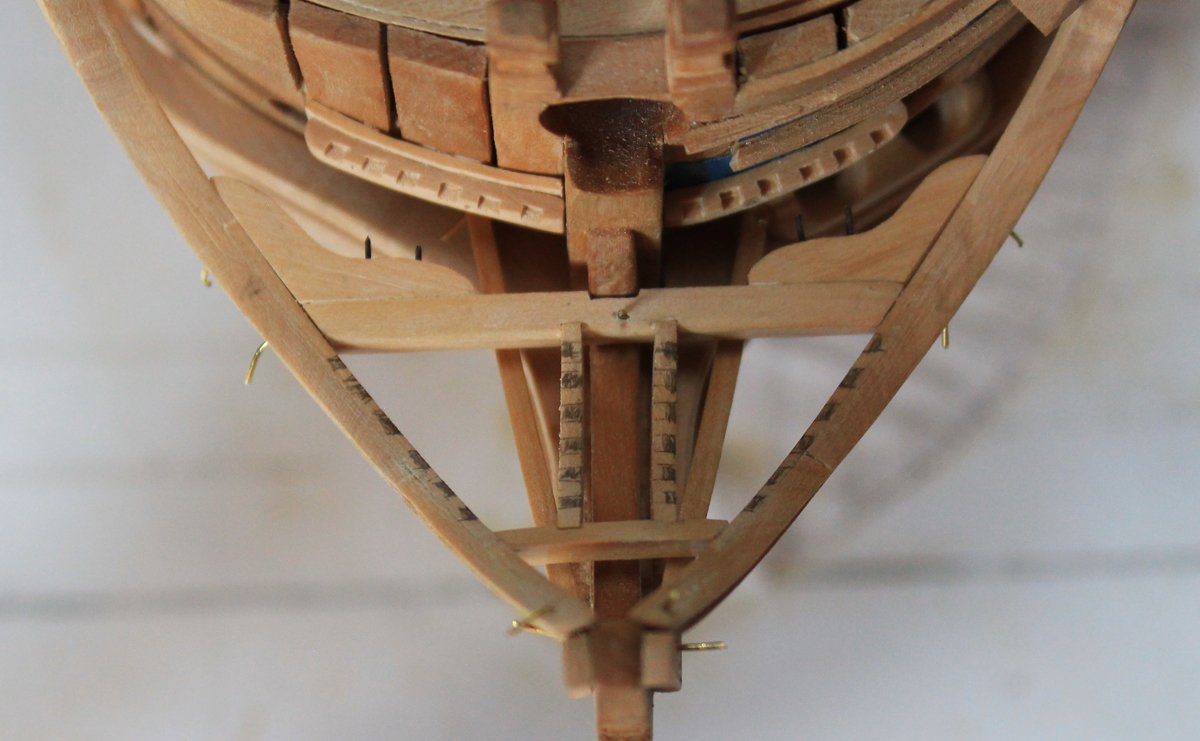
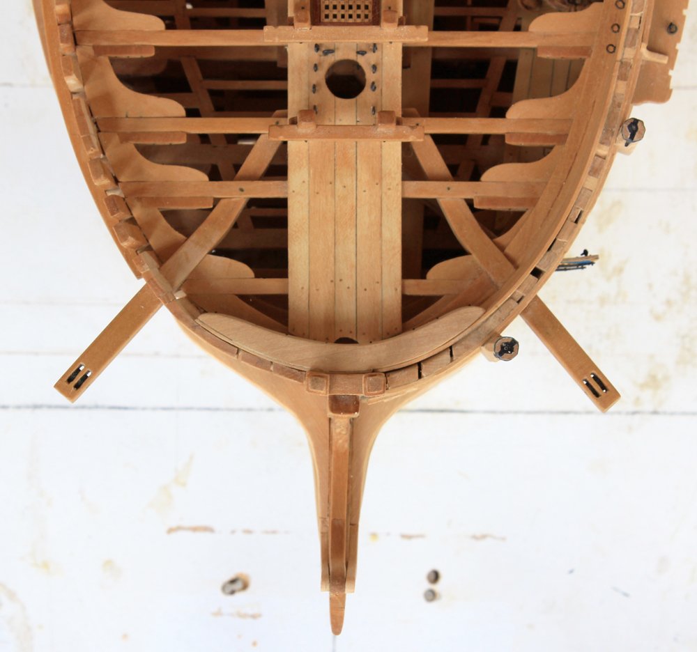
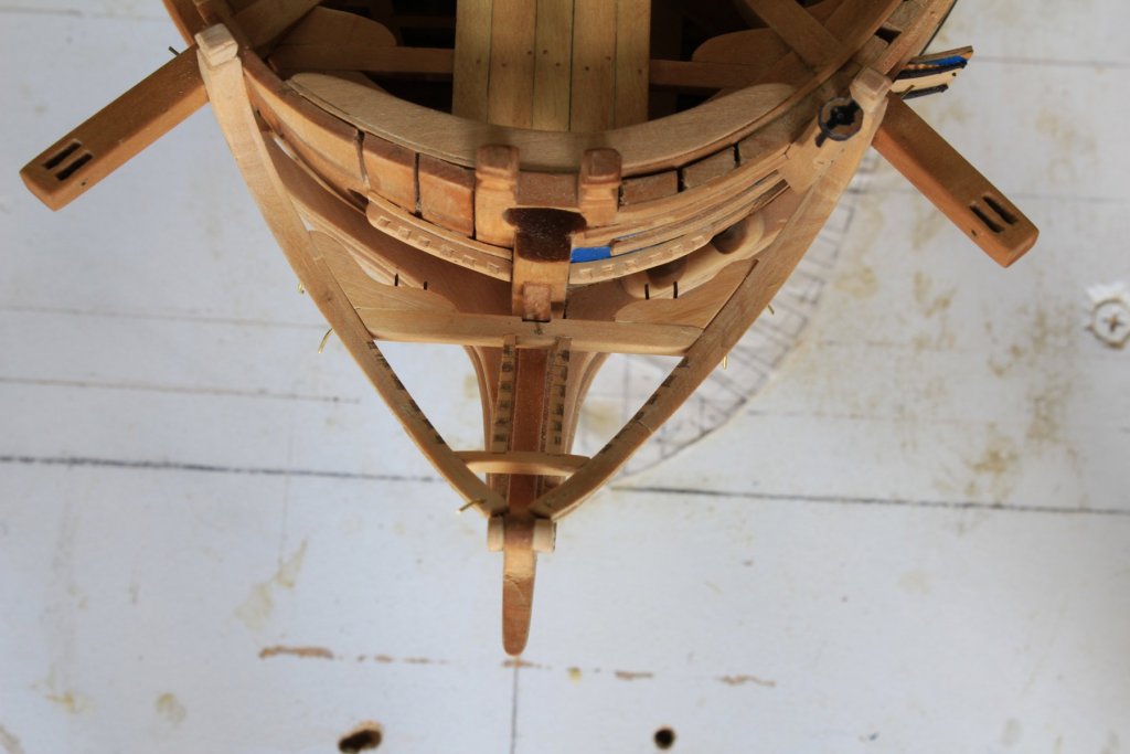
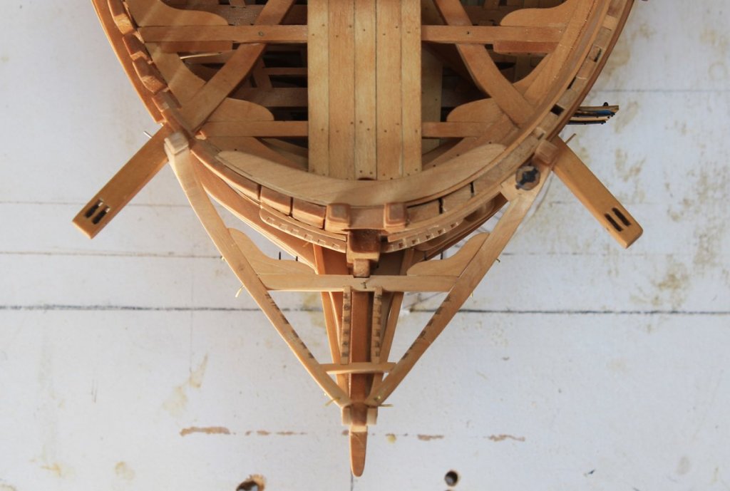
I have finally had some time to devote to the workshop. Construction has resumed on the head structures. There is a grating on top of the main rail. This is supported posteriorly by the head beam and anteriorly by the cross-piece. The head beam has two knees on its posterior face, connecting to the main rail. In front of the head beam, the grating mortices into the lining of the main rain. Behind the head beam, the grating connects to the hull with the use of a morticed bolster. There are openings in the grating to accomodate the fore seats of ease. I forgot to take pictures during the process so what is shown are the deconstructed structures after it had been partially completed. You can see that everything is pinned together. If only one thing shifts, the rest of the construction will be wrong. In the first two pictures the battens, cross-piece and head beam assembly are in place and the carling and liner are marked for the grating. The next two pictures show the curvature of the carling of the head and how it mortices into the cross-piece. The third photo shows all of these structures in place.
-
I used the monograms from Syren on Atalanta. I was very pleased with them. Take a look at my build log.
-
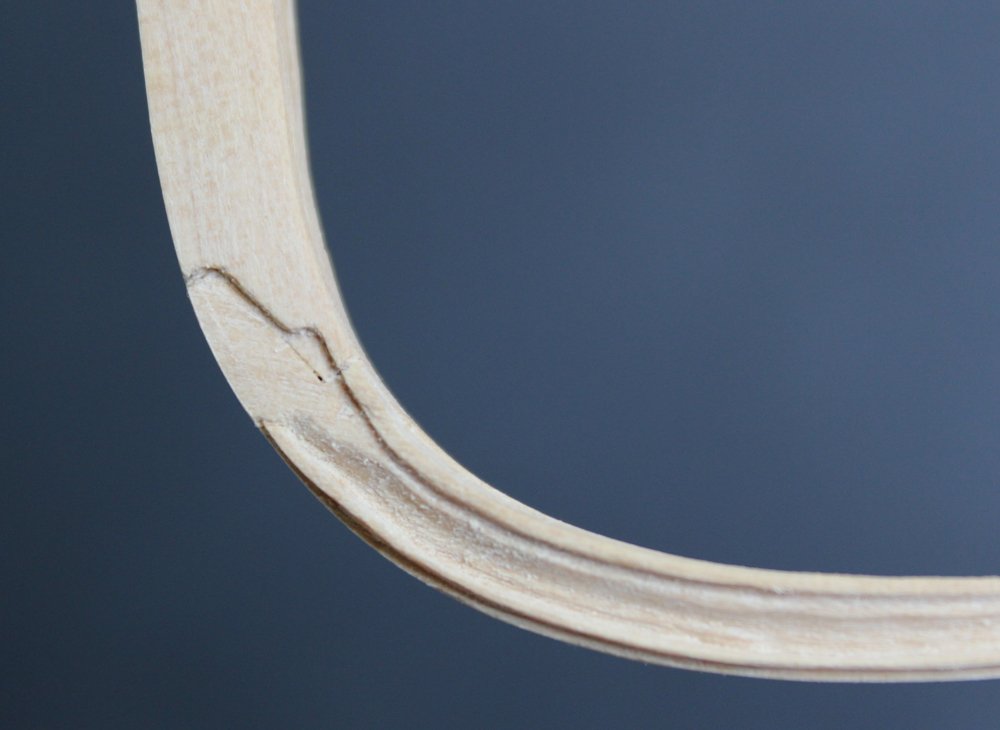
Thanks Danny. I can barely see the laminations, even when I am looking for them. My thoughts were that even if it looked badly I would have a perfect template to work from for the redo. Thank god, that was not necessary.
-
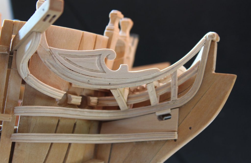
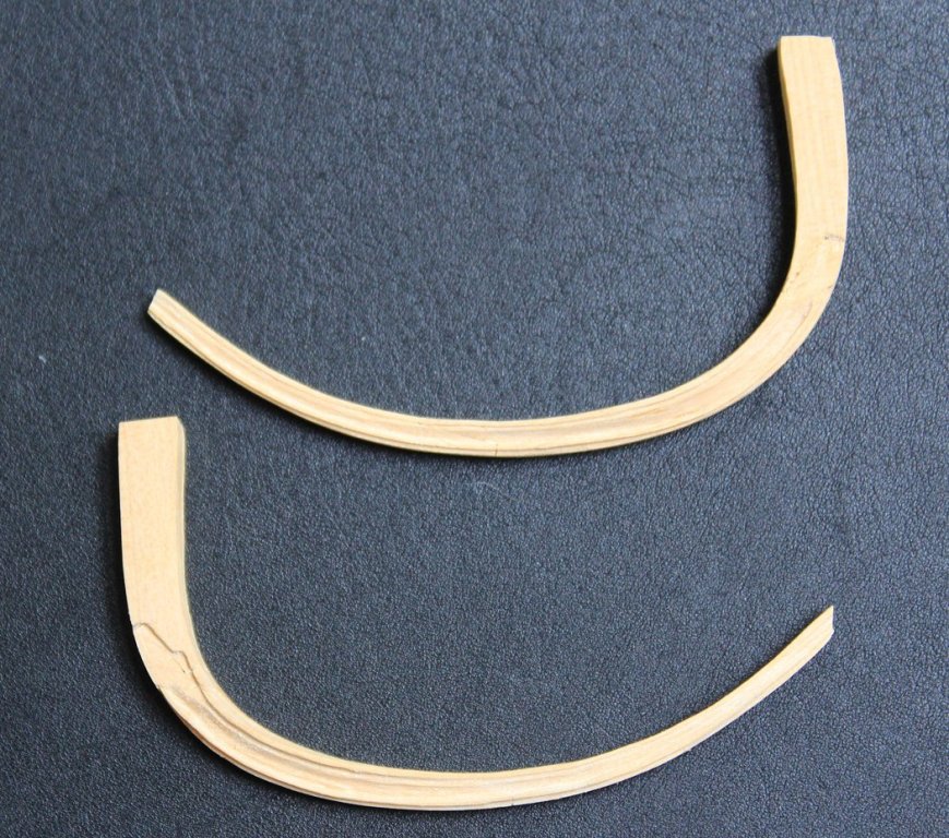
Thanks everyone for your words of encouragement and the likes. And yes, Druxey, it does get easier. Before the figurative ink dried on yesterday's post I decided that I could not live with how the upward extension of the rail looked. I put three very thin layers of lamination on the for end of the rail extension so the angle could be adjusted. By putting several layers, the eye is tricked into "seeing" the grain of the wood whereas with one layer the added piece would be obvious. I am much happier. I also added the bolster for the hawse holes. The timberhead height was determined from the plan. The heads were then cut in.
-
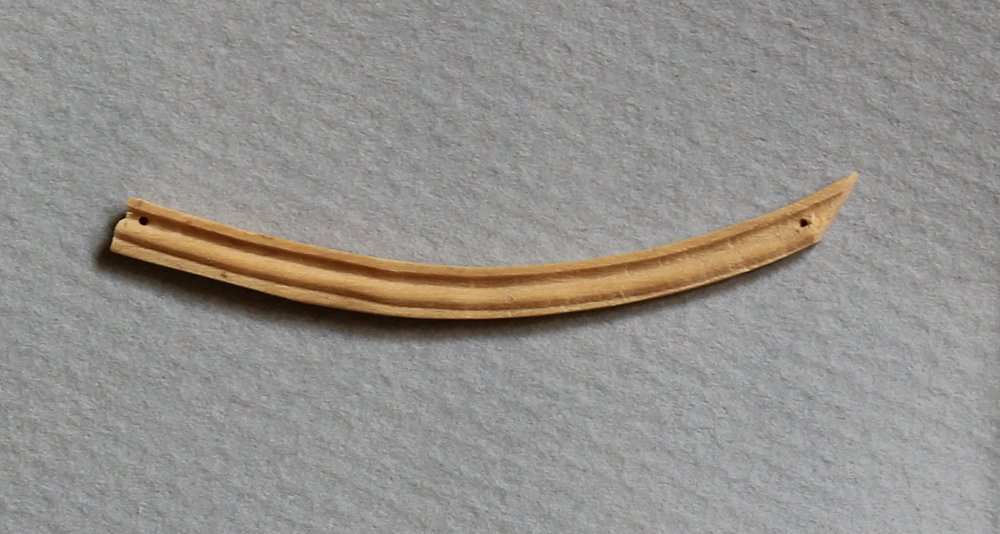
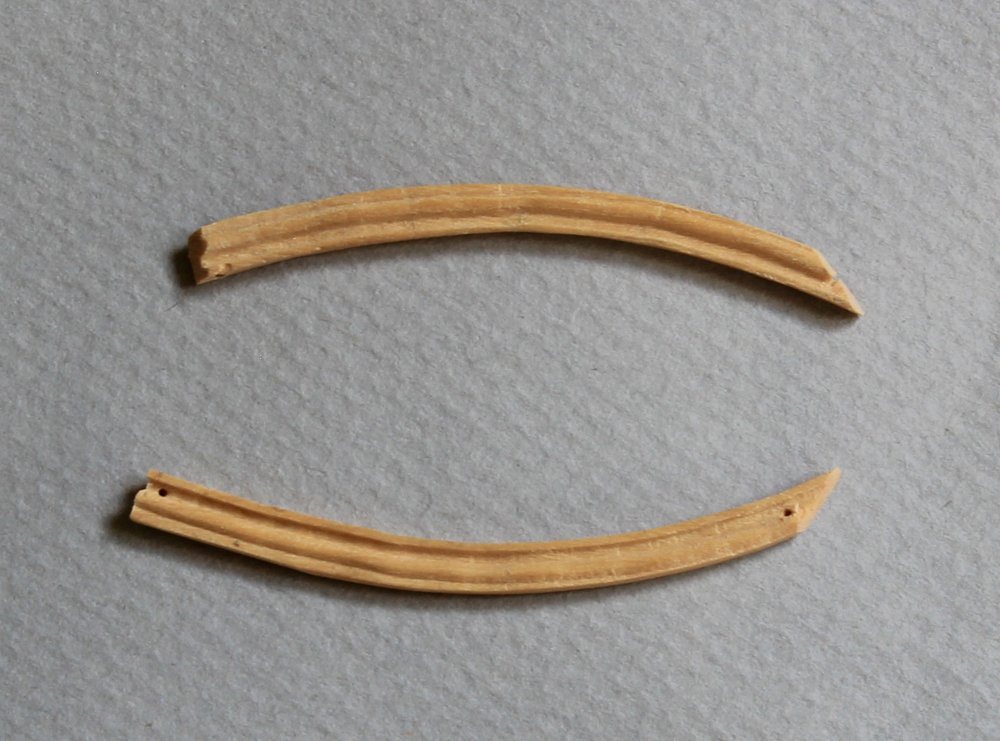
I has been forever since my last post but I have two excuses. The first (painful) reason I back in December I agreed to restore a clipper ship model for a friend. Yes, I know..."just say no". But I was suckered into it, not realizing that every stick needed work and every piece of rigging needed replacing. Two hundred plus hours later I am done and can concentrate on Atalanta again. The second excuse is that the next items to make are the main rails of the head. This has been the hardest part to fabricate, bar none. They are not finished yet and they are far from perfect but so far I have put in over 40 hours over the last month trying to get them as close to OK as I can. The first step is to develop the shape for the main rail. TFFM describes how to make a projection drawing from the plans. Once the shape of the rail had been roughly determined, I made a template and fit this to the model. I used cardstock which, in retrospect, was not stiff enough. After the final shape is determined, the individual pieces must be cut out. The main rail is comprised of five scarfed pieces. There is a lining to the main rail which is made of three scarfed pieces. First I made the main rail and then the lining was made by gluing the pieces directly onto the main rail. This is the easiest part of the whole process. Now comes the real fun. There is a reasonably complex molding cut into the main rail. In addition, the rail tapers in width and thickness so the molding changes continuously along the rail. Finally, scrapers work best on a straight line, not on a curved object. I made two scrapers, one for the aft third and one for the middle third of the rail. The fore end of the rail was cut in with micro-chisels and needle files. I spoiled a few rails before I finished two that look reasonable. Since the port and starboard rails are mirror images, the whole scraping motion is different on the two sides. There are two step-downs on the aft part of the rail. The first one goes down to the level of the rail without the planksheer and the second is where the molding starts. The ascending (aft) portion of the main rail is supposed to be perpendicular to the water line and the fore end blends into the top of the hair bracket. You notice that I say "supposed to". This is where I have gotten into a little trouble. I believe my template was not stiff enough and the angle of rise of the tapering end was not great enough. Consequently, my ascending portion is not quite perpendicular. After so many hours of work, the thought of redoing them was more than I could handle. The aft end of the rail has a score in it for the cathead. Two drill holes are placed after temporarily gluing the pieces in place. Later these holes will accept wire bolts for security. The next step is to make the timberhead, now that I have the height correct.


-
ancre Chebece 1750 by Jeronimo - FINISHED
tlevine replied to Jeronimo's topic in - Build logs for subjects built 1501 - 1750
Absolutely beautiful, Karl. -
She's looking very sweet. Add me to the list as well. Are you coming to the Conference in October? It would be a great time to show her off and boost pre-publication sales.
-
The "like" button
tlevine replied to kscadman's topic in Using the MSW forum - **NO MODELING CONTENT IN THIS SUB-FORUM**
Eric has hit the problem on the nail head. Many of us still have real jobs and we all have real lives. Sometimes I am unable to do serious post reading for a week at a time. By then, there is little incentive to add to the thread. Also, with limited time to dedicate to the hobby, I have select areas that I read w/i MSW. For example, I rarely look at the kit builds and shore leave. -
Birchwood Casey, like most blackening liquids works best diluted. I typically use a 1:3 BC:water solution that I keep in a separate container (aka pill bottle). I reuse this but never contaminate the original bottle. Cleaning is the most important part. Many modelers use a heated Sparex solution. I typically start with soap and water, followed by a good soak in 90% isopropanol. Finally, for something large like a cannon, I apply a coat of clear matte finish to protect the blackening. Be careful with those wire brushes. Unlike painting, which fills in tiny imperfections, blackening will potentially highlight those wire brush marks. There are liquid CA adhesive removers but either soaking in acetone or iso. should take care of it.
-
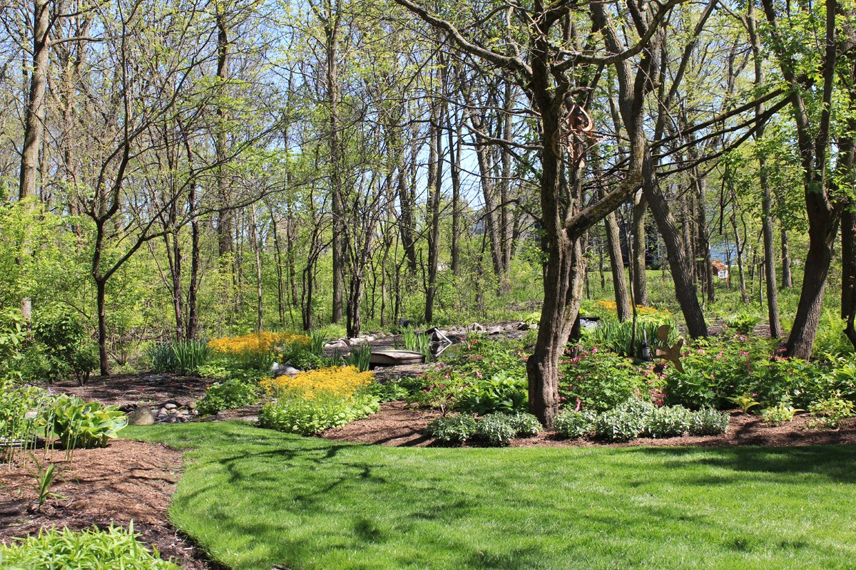
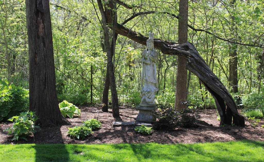
Thanks, everyone. Greg, the statue is a Chinese woman. I know nothing about it other than one of our neighbors was throwing it out and I took it.
-
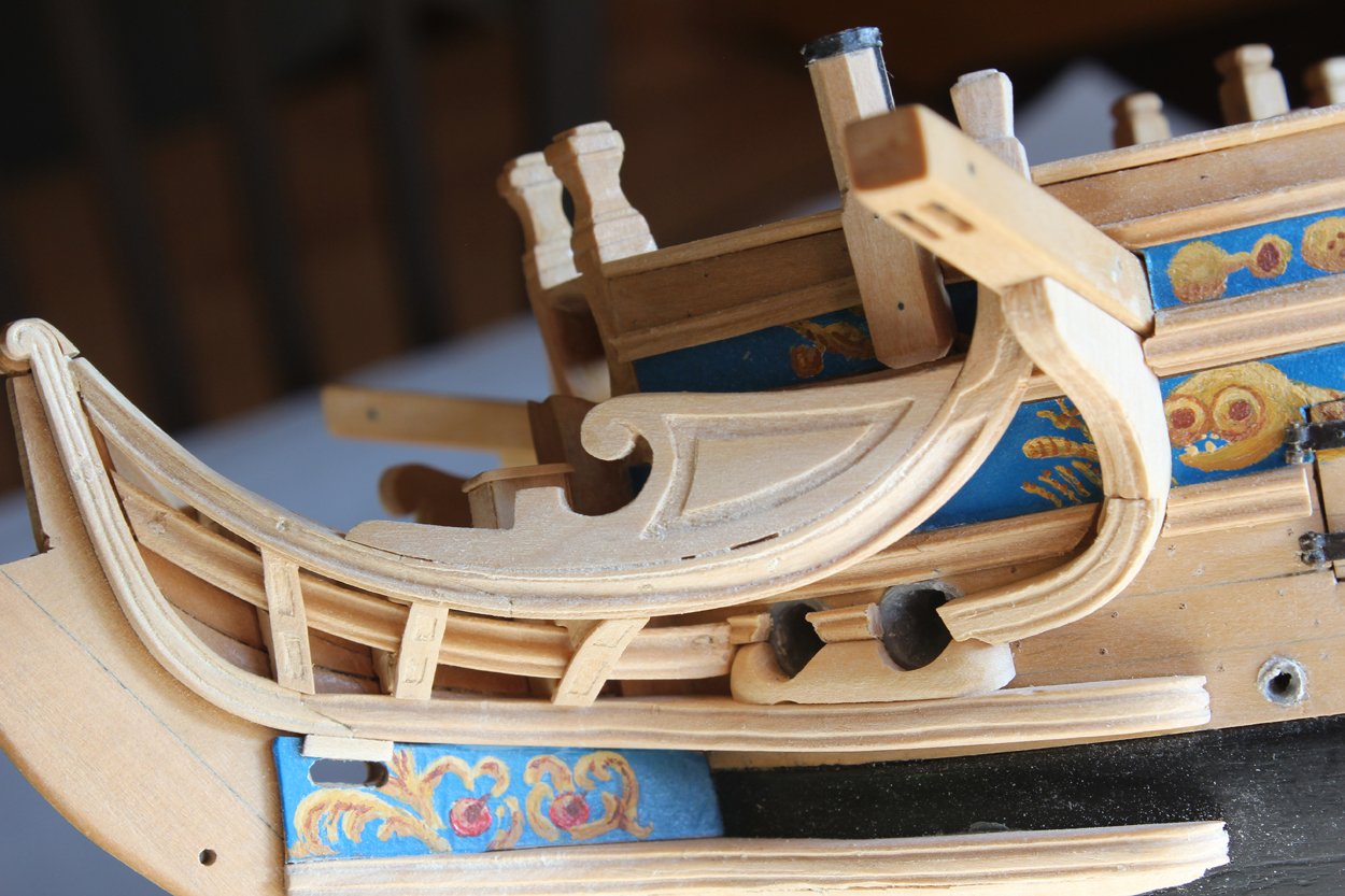
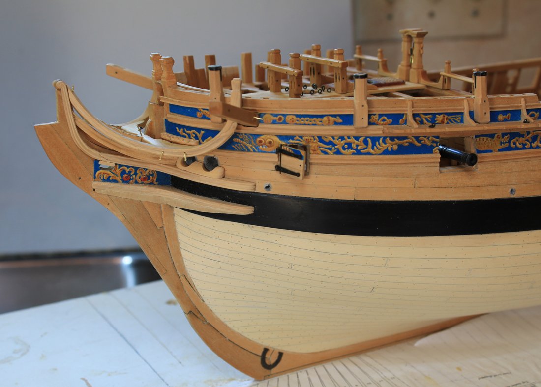
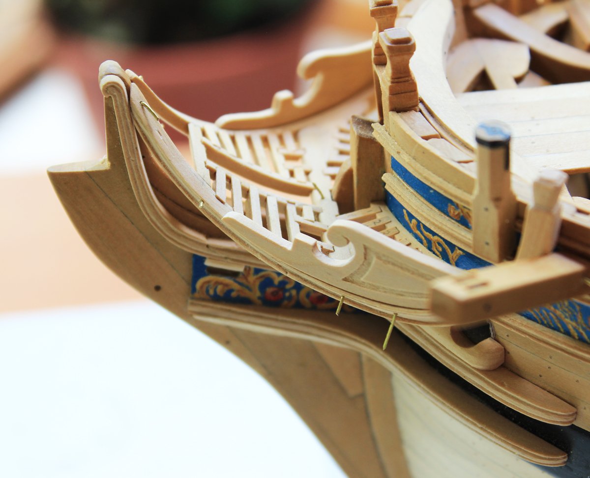
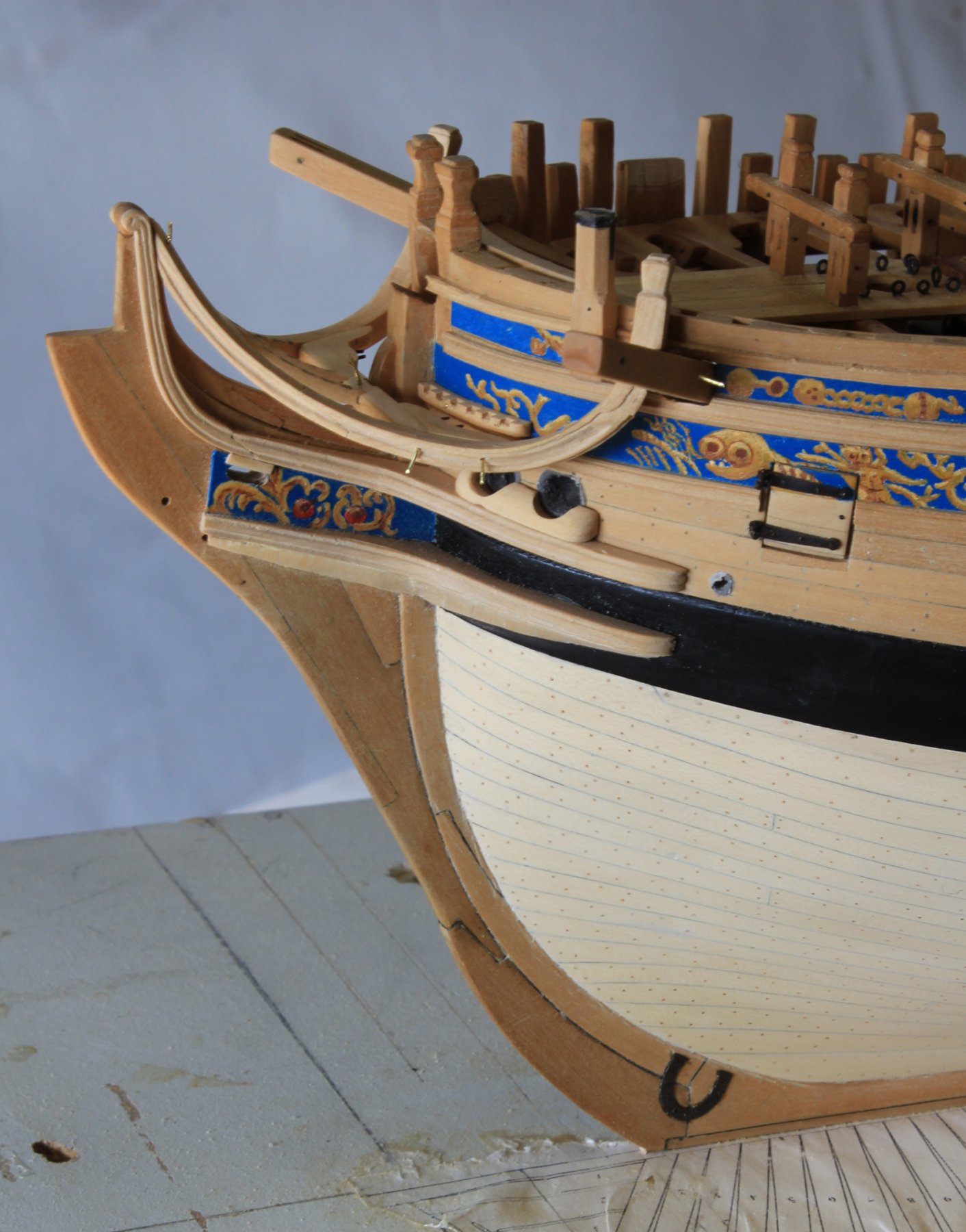
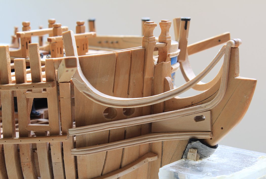
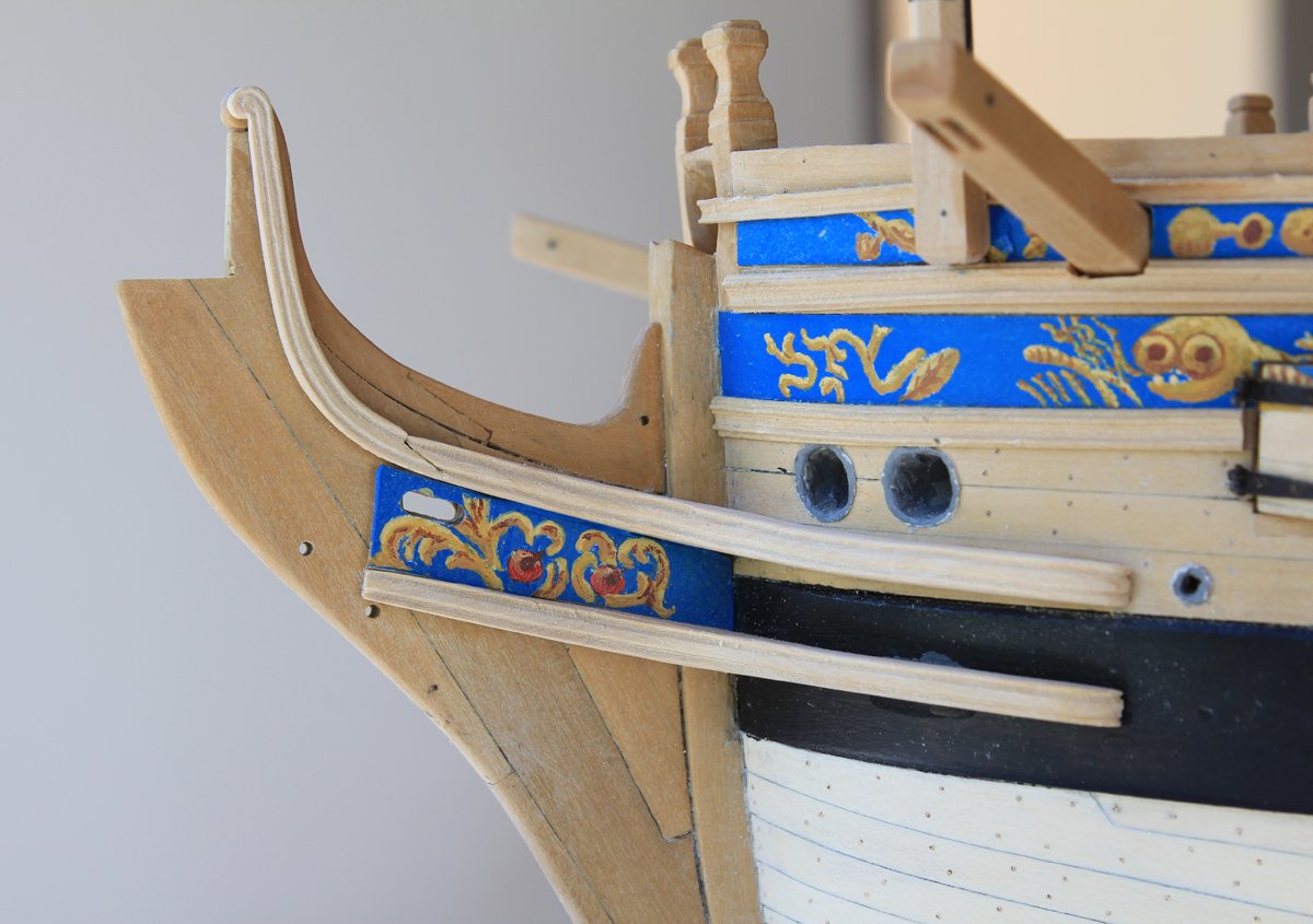
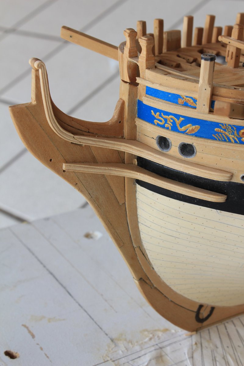
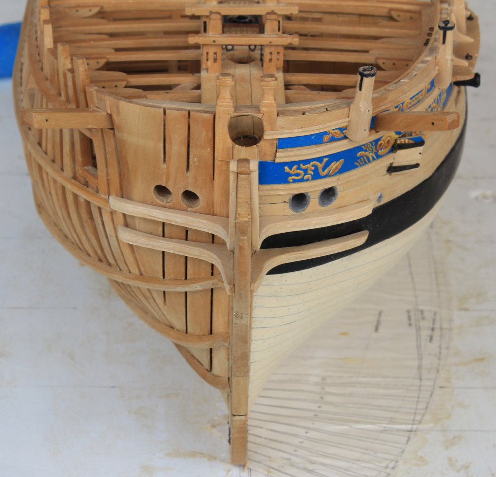
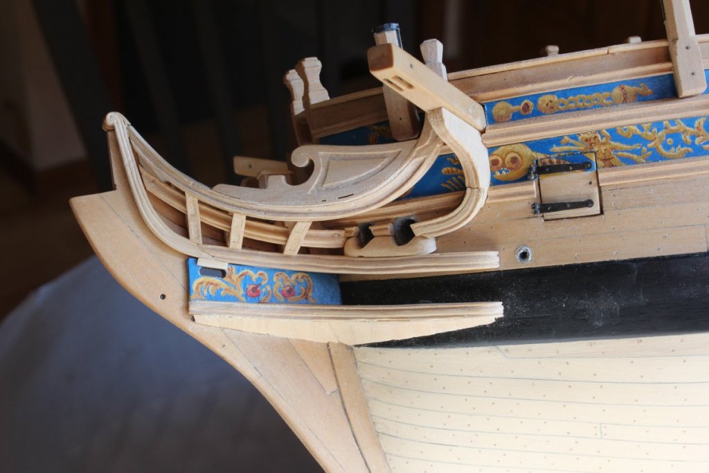
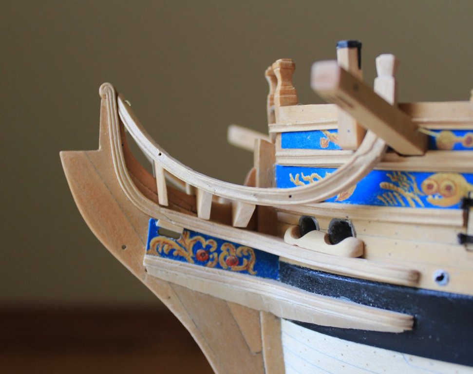
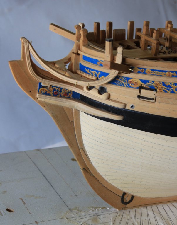
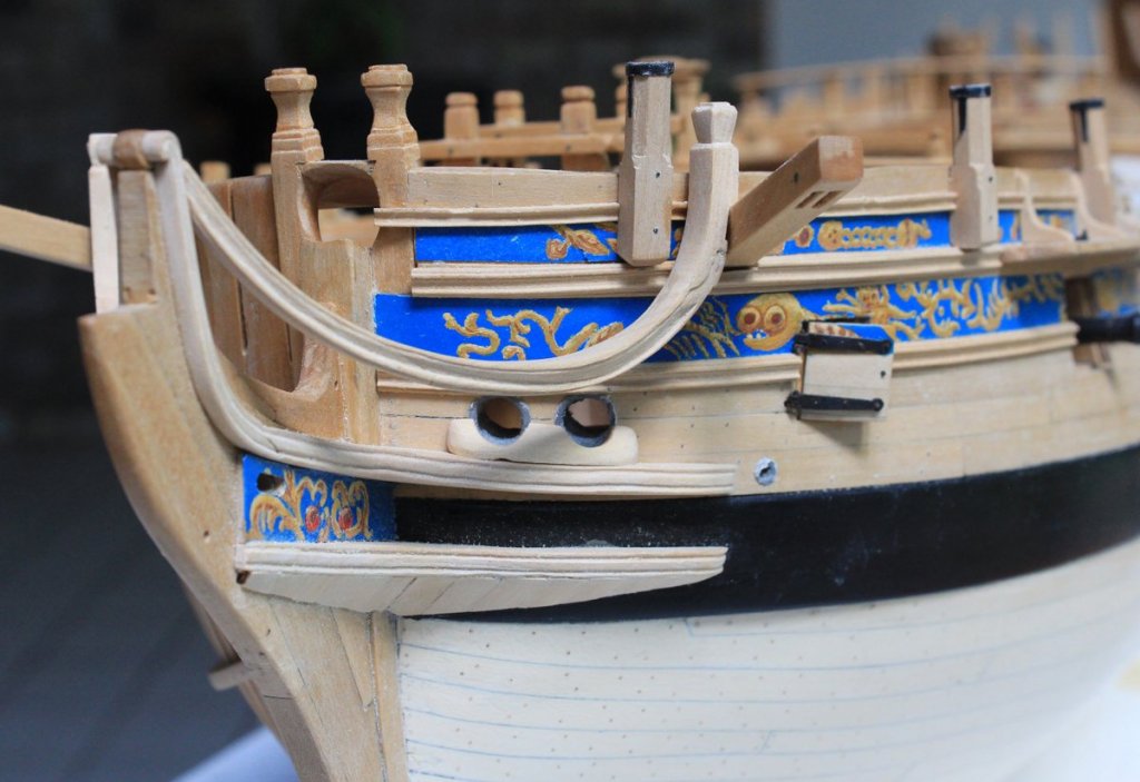
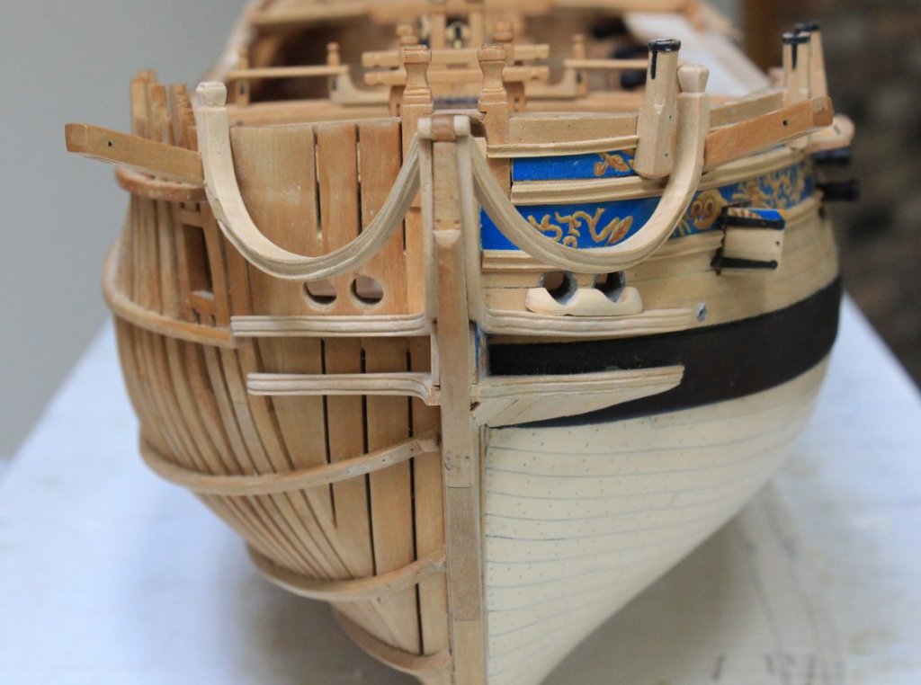
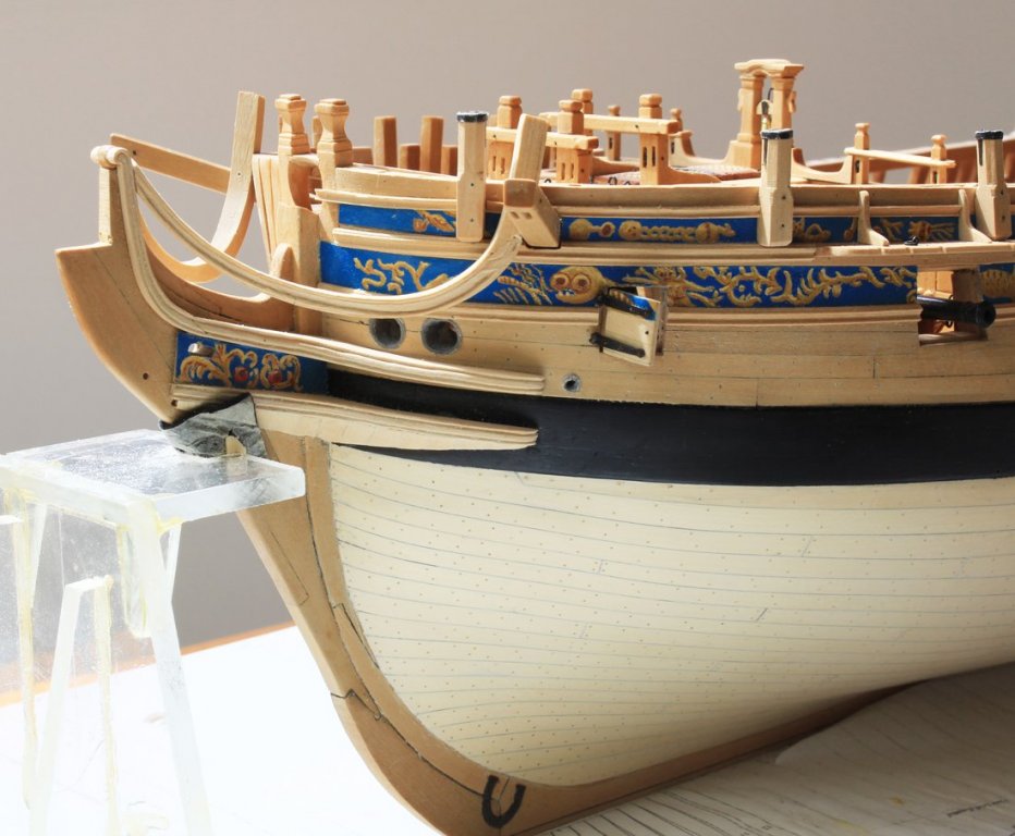
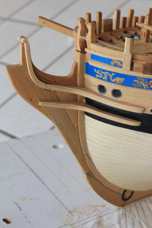
Not too much to show for this weekend's work The weather has been so bad for the last several weeks that the garden called to me louder than the workshop. I had just enough time to make the trail boards. These are located between the upper and lower cheeks. There is a hole through it for the gammoning. On Atalanta there is a frieze painted onto it. This show's two of Atalanta's apples. On the Fly, the only other Swan class whose plans I have, there are two dragons on the trail board and the cheeks are decorated as well. I left the starboard side unadorned and put the frieze on the port side. The gap between the starboard trail board and the hull represents the thickness of the planking. The frieze was made the same way the rest of the friezes were made, painted onto paper and then applied to the wood with a thin layer of glue.


-
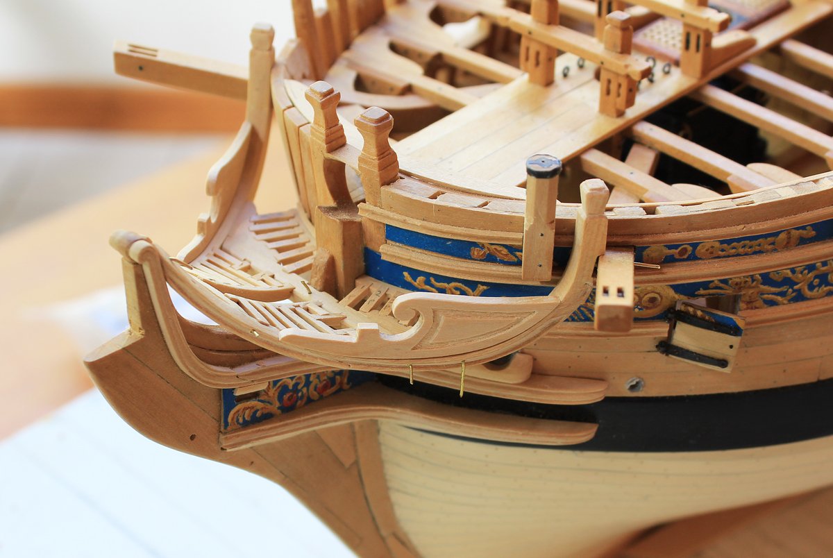
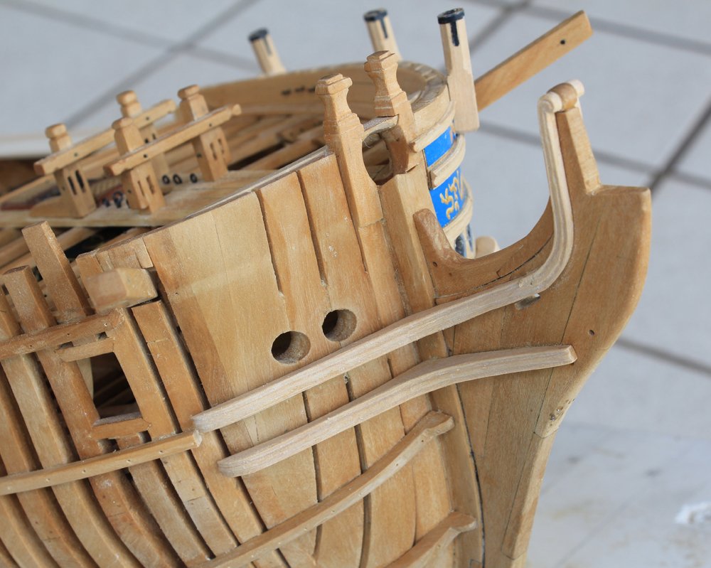
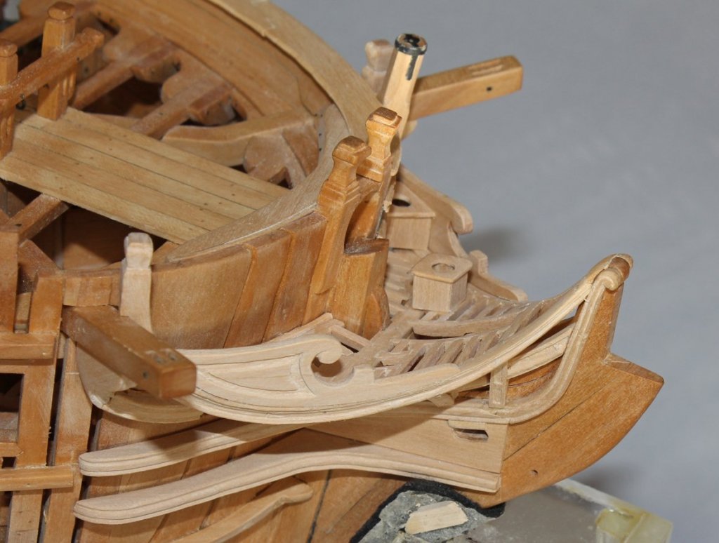
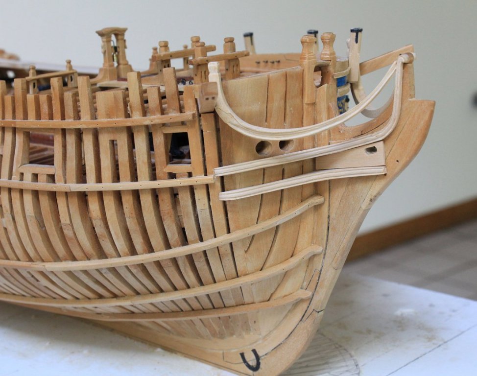
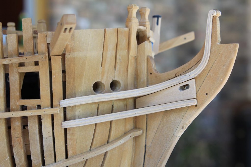
Thank you everyone for the likes and comments. Time to move on to the head. This is an absolute birds nest of inter-related structures which appears daunting but (so far) is not horribly difficult if one fabricates and installs one piece at a time. Sorry that there are no construction pictures but taking photos of 3-D objects while keeping everything in focus is beyond my simple camera. The key to each structure is one word...template. The lower cheek is constructed first. Make a template in the horizontal plane. On the plan, determine the total thickness of the cheek, remembering that there is a gentle curve upwards as the cheek follows the knee of the head. Also remember that the hull drops away inferiorly so make the aft arm wider than per the plan. Draw out the templated cheek on the wood, keeping the arms along the grain as much as possible. Cut out the rough blank and offer it up to the hull until a good fit is achieved; It is still oversized in thickness at this point. Next, draw the curve onto the side of the blank and shape it with sanding discs. The edge of the cheek has a molding cut into it. Make another scraper (since none of the other shapes made so far are correct) and carefully scrape the shape onto the cheek. Simple, right? Actually, very tedious although not technically difficult. The first one took four hours to complete. On my model the starboard side is unplanked so there is a gap between the frames and the knee corresponding to the thickness of the planking. The upper cheek is made in similar fashion except that it must fay into the hair bracket with a scarf. On Atalanta it is slightly thinner than the lower cheek at the aft end and tapers in width going forward. That simply makes adding the molding even more fun because the fore arm molding must be cut free hand. The hair bracket is simple to make after the cheeks are installed. Again, make a template. The molding is cut in free hand because the width continues to diminish on the ascending arm. I used a dull #11 scalpel to gently impress the design. Then a 2 mm V-chisel was used to cut the groove, changing direction as necessary to always cut with the grain. Finally, it was finished with jeweler's files. The scarf was cut into the hair bracket first. This was then drawn onto and then cut into the already installed upper cheek. The hair brackets were installed and the joint cleaned up so that the molding flows between the cheek and the hair bracket. This can be seen when one compares the second and third photos below. The total time invested so far on the headwork is two weekends.


-
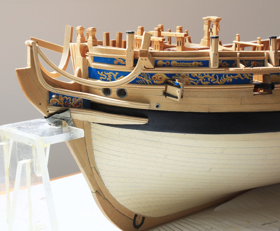
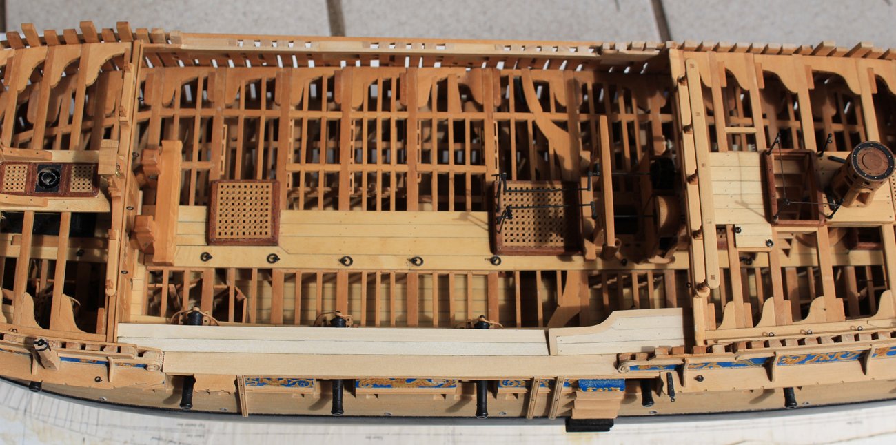
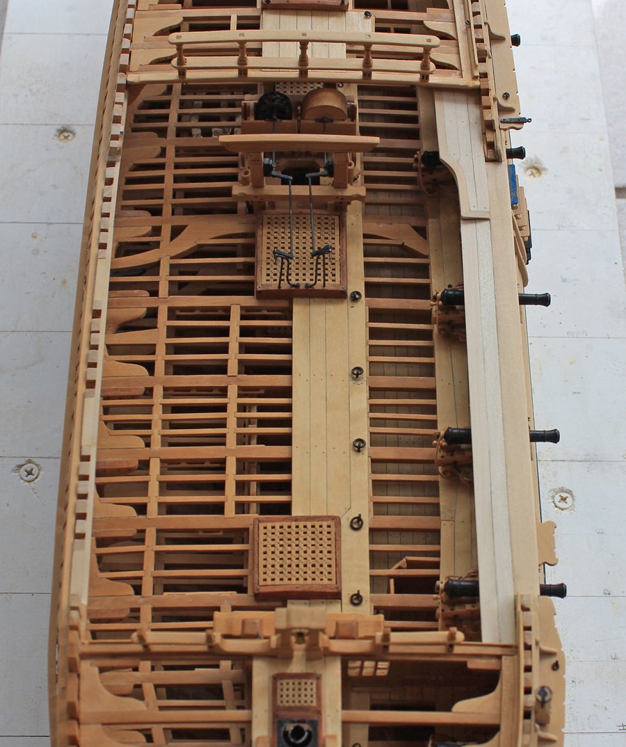
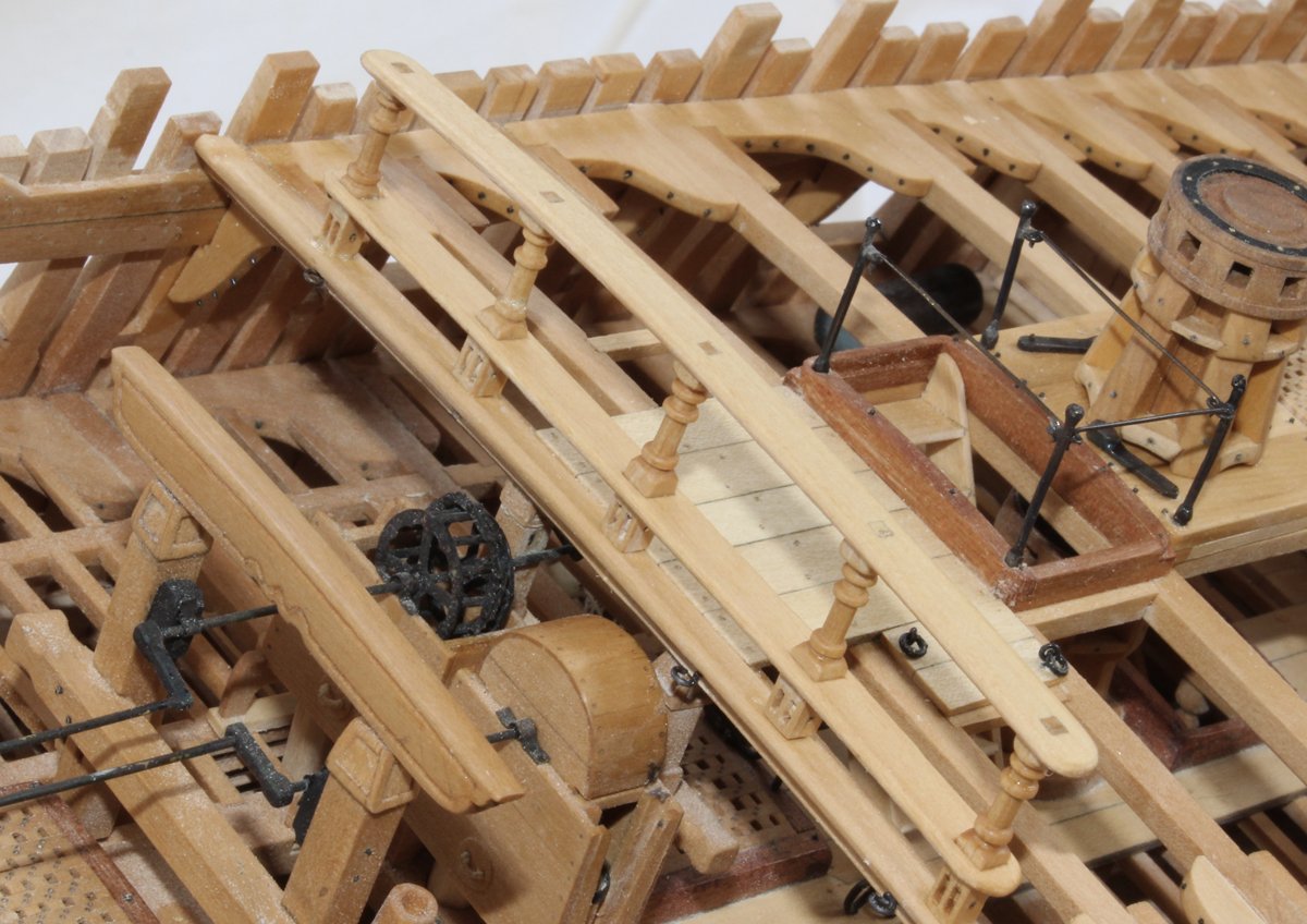
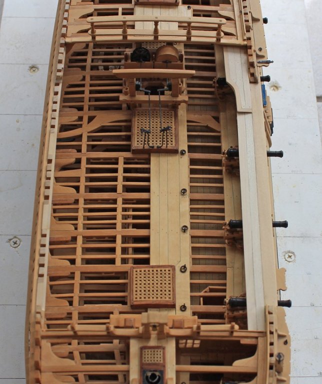
Well it has been quite a while since the last update. I had the pleasure of spending a two weeks abroad and then had to catch up on everything which was neglected during that time. The next item to tackle was the fixed gangway. It is comprised of a lightweight frame with planking. This platform is situated a few inches lower than the quarter deck breast beam. It is attached to the undersurface of that beam and the fore end is supported by a hanging knee. There is a newel post at the aft end of the curve but this will be made later. I found the description in TFFM a bit confusing, and hope I interpreted it correctly. The text states that the outboard edge of the gangway is above the level of the planksheer (by about 2" in the sketch) and that it is canted at the same angle as the deck beams to facilitate drainage. In looking at Atalanta's plan and comparing it to Fly's it looks like the outboard edge on Atalanta is at the planksheer, not above it. So this is what I have constructed. Please chime in if I am wrong in my interpretation as it is easy enough to correct at this stage. The planksheer was installed next. There is a decorative molding on the outboard edge. The gangboards extend from the fore end of the fixed gangway to the forecastle breast beam. The rest of hanging knees which were installed earlier. There is a breast hook overlying the bowsprit opening. A shim was placed under the starboard arm of the breast hook to simulate bulwark planking.


-
I actually use the Preac more than the Byrnes saw. I use the Byrnes primarily for more heavy duty cutting. I feel like I am less likely to accidentally injure myself with the Preac. Since I travel a lot, the Preac is a lot more portable as well.
-
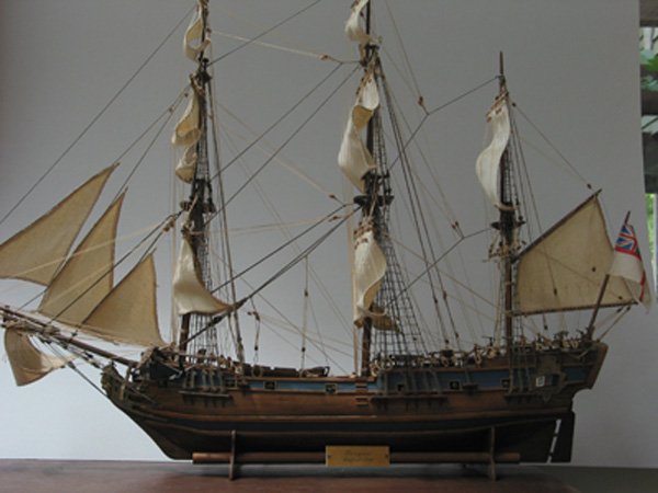
This was also my first wood ship model back in the "80's. I look at it in horror because of all the mistakes (mine and Mantua's) but friends think it looks great so I still keep it on display in my living room. Use this kit to learn and hone your skills.
-
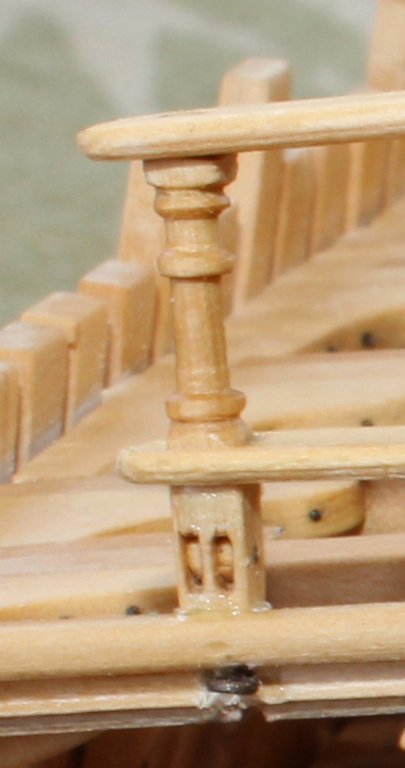
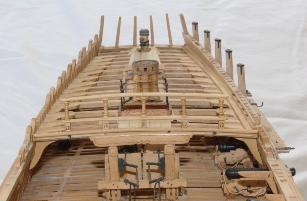
Thank you everyone for the compliments and likes. Yes, the stanchion is all one piece. Chuck, I like the GPS idea better!
-
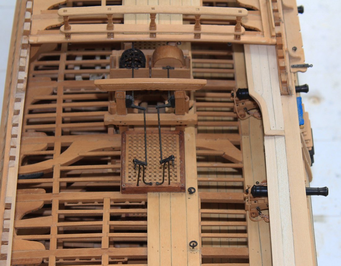
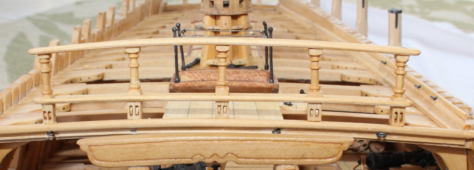
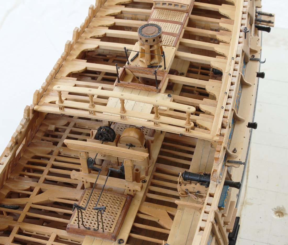
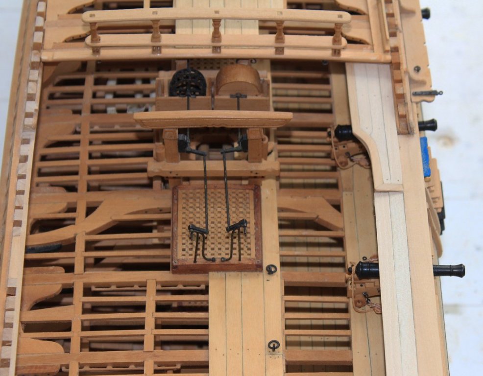
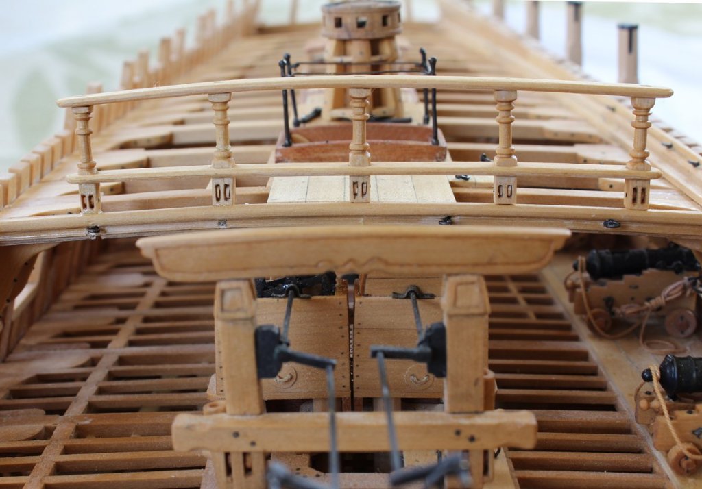
The next item on the agenda was the quarter deck rail. All told, this took me about 20 hours to fabricate and install. There are no construction photos but I will do my best to describe the process. There are five stanchions and a double rail at the break of the quarter deck. The stanchions are morticed into the breast rail inferiorly and the upper rail superiorly. They pass through the lower rail. The rails have a beading scraped into them but the thickess is so small, 0.065", that the beading is barely notable. The stanchions were made as follows: The profile of the central portion of the stanchion was cut into brass sheet stock as both a template and final shaper. (I use very thin dental cut-off discs for this operation.) Square stock slightly larger than the finished dimension was chocked into the lathe. The central portion of the stanchion was then turned just enough to remove all the edges. Then the profile was roughly shaped by eye. Finally, the template was used as a scraper to provide the final shape. Slots were drilled and cleaned up for the sheaves. These are simple discs, turned with a Dremel and sandpaper to the correct diameter and then center-bored before cutting off to prevent splintering. The rails were shaped by placing them in a moist paper towel in the microwave...low power and 10 second bursts. They were then clamped to a curved chair back to dry. It is very fiddly to get everything plumb and square, especially when the deck and the rails curve. My sequence was to first insert the stancions into the breast rail mortices. When the glue was set but not dry I inserted the lower rail and glued it into position. After that was set I added the top rail and clamped everything to dry. In the picture above, I still have to remove escess glue. It really looks better than the photo would suggest; on my computer screen this is 5X magnification. It looks better in the next photo. It also looks like I have a ring bolt to replace!


-
Are you an NRG Member???
tlevine replied to Chuck's topic in Using the MSW forum - **NO MODELING CONTENT IN THIS SUB-FORUM**
No time like the present to renew, Sam!