HOLIDAY DONATION DRIVE - SUPPORT MSW - DO YOUR PART TO KEEP THIS GREAT FORUM GOING!
×

tlevine
-
Posts
2,032 -
Joined
-
Last visited
Content Type
Profiles
Forums
Gallery
Events
Everything posted by tlevine
-
 Druxey, Pete, Ben and David thank you. Thanks to everyone for the likes as well. Nothing to show this week as I am spending my free time in the garden.
 -
I cut the sills for the gun ports on Atalanta after all of the frames were erected for fear of having the ports out of alignment. And overall I am happy with the results. I was also lucky enough to attend David's and Greg's Echo symposium after the framing was completed. David showed my how to make the perfect birds-mouth and it looks a lot more refined than my approach. The next model will be made as Druxey suggested. The frames that require gun and/or oar ports will me mounted temporarily and the notches cut off the model once all the frames have been erected.
-
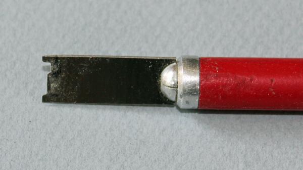
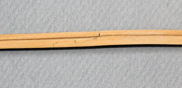
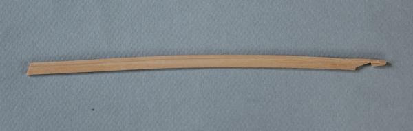
I have made and installed the waterways. On this deck the waterway looks like a chair resting on its back. To make the shape I took an old Dremel chisel blade and carved the shape into the end of the blade with thin cut-off discs. The scraper was then cleaned up with a Swiss file. I forgot to take pictures until I was almost finished, so I will describe the sequence. I used drafting paper to make a template of the inside of the hull. This was transferred to 5" thick stock and the segment was roughly cut out. The waterway is only 4" thick but I made the stock over-thick in case I made an error with the scraper and gouged the surface. The outer edge was then fit to the interior of the hull and the scarf was cut. I used the scraper to scribe the inner edge of the waterway. A sanding disc cut away the excess material on the inner edge and the scraper was used to form the top edge. Various grits of sand paper smoothed everything out. I was more concerned with a fair line on the inner edge since the spirketing will hide the outer edge of the waterway. I started at the bow and worked aft. After the first plank was installed, I made the next two planks, gluing them together at the scarf before installing them on the deck. Finally, I made the aft plank. The next three photos show the sequence of fabrication of the plank. These photos show the waterway installed.

-
I am jealous. Do you use a halogen or xenon light source for your headlight? When I was making balusters on Victory I used to bring wood in to the office and carve them under the operating microscope. Drove my nurse nuts.
- 728 replies
-
- 3
-

-
- le fleuron
- 64 gun
- (and 1 more)
-
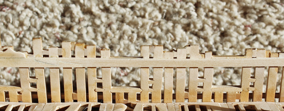
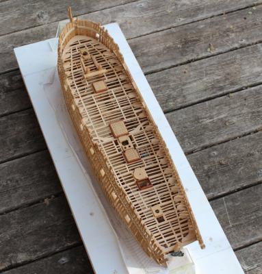
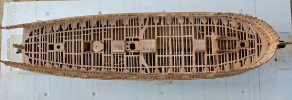
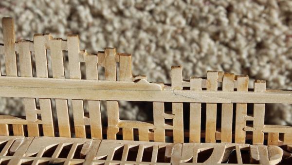
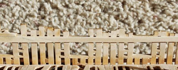
Martin and David, thanks for looking in. Thanks for all the likes as well. I am installing the port stops on the port side only since the starboard side will be left almost completely unplanked The stops for the gun ports are 1.5" thick and the stops for the sweep ports are 3/4" thick. The exterior planking will come up to the outside edge of the stop and the interior planking will cover the stop completely. I am using this as an opportunity to fine-tune the size the port openings. The foremost gun port was too wide and so an extra layer of 1.5" plank was applied to correct the width. I did not take any pictures as this is pretty straight forward. I am still trying to decide how much planking to put on the upper deck. The starboard side will be left unplanked (as on the lower deck) but I am thinking of leaving the port side partially unplanked as well to improve visibility to the lower deck. I have been looking at various build logs and photos to help in my decision but am leaning towards planking the area between the hatches, the first binding strake and the outer rows of planking to provide support for the gun carriages.
-
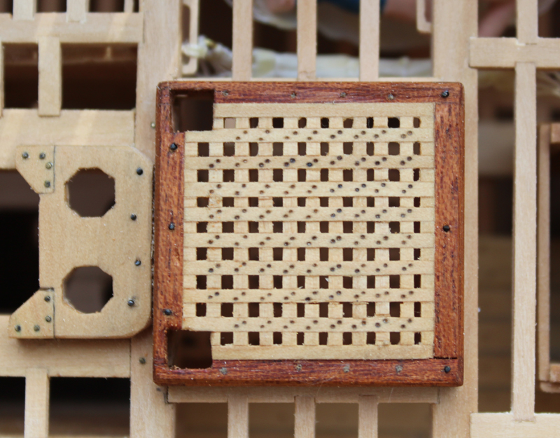
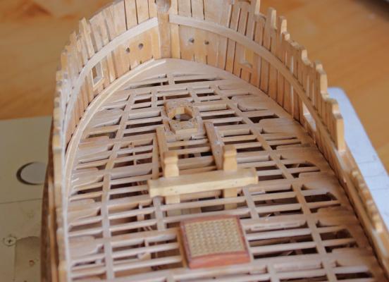
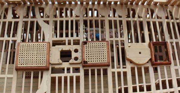
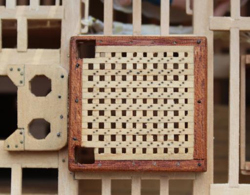
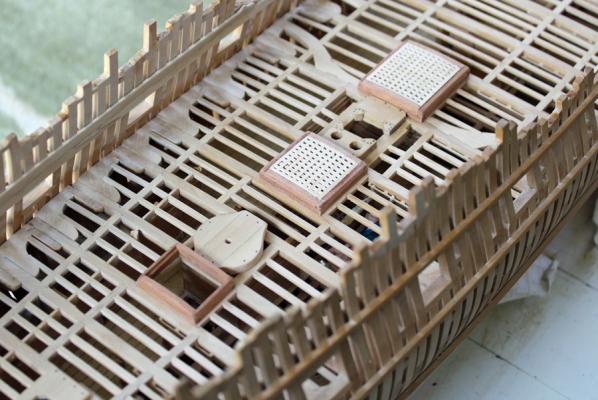
Not much to show for last weekend's work. The garden has taken over most of my free time. I have completed the upper deck hatches and ladderway. The head ledges are bolted to the deck and the coamings are treenailed. Even though I used a light colored wood for the treenails (bamboo) they are barely visible. The nails securing the grating battens to the ledges were made by making a dimple with the point of a compass and then highlighting it with pencil. I scribed the main hatch cover to simulate a three piece cover.Openings have been cut into the aft hatch cover to accommodate the main jeer bitt pin. This will not be installed until I am ready to work on the quarter deck beams to prevent damage.
-
The moldings look great, especially with the curve. Did you free-hand it or make a scraper?
-
David, the color contrast of holly is too stark with the cherry coamings. Since these pics were taken I have added the treenails and bolts. New pictures this weekend.
-
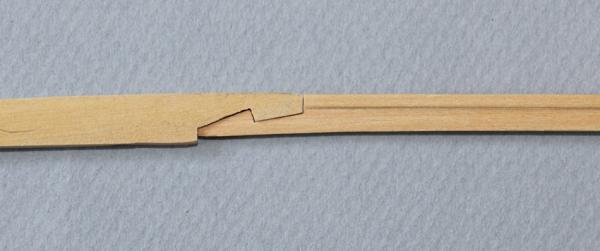
Floyd, take a look at the picture showing the scarf between the stem and the keel. It should fit perfectly without any sanding except to remove the char from the laser. It appears to be rotated upwards. If the shape is wrong, the entire bow will be incorrect.
-
The most influential book I have read was Longridge's The Anatomy of Nelson's Ships. I was in high school working on Scientific's Bounty and went to the local library lookng for information on the ship. That was my introduction to ANS. I have my own copy now and used it extensively when I was building the 1:96 Victory by Mantua. Someday I will even finish the rigging!
-
Tom and Druxey, thanks. And thanks for the all the likes. Tom, tell me about the jig Greg uses.
-
Thanks Ben. I used castello for the gratings. It looks lighter than the beams because of the cherry coamings.
-
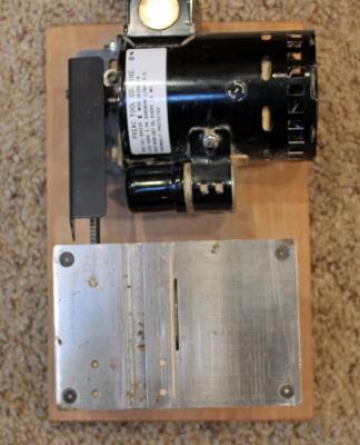
Finally got a little time this week to work on the ship. I have made the upper deck hatch coamings and have started on the gratings. I forgot to take any pictures so let me verbally summarize the construction. The fore-and-aft pieces (coamings) have a rabbet to accommodate the ends of the grating strips. There is no rabbet on the athwartship pieces (head ledges). On the lower deck coamings I made a simple half-lap corner. The actual construction technique involves angling the mortise in both the x and y planes, effectively locking the pieces together. I simplified this to angling only the x plane (the y plane angle would not be visible). In contrast to the lower deck coamings, these taper towards the top rather than being slab sided. The top of the coaming is curved to match the curve of the deck beam. The top of the ladder way is parallel to the water line whereas the hatches follow the angle of the deck. Dan (shipmodel) showed a method on QAR for making serrated strips for hatch gratings that I stole. Thank you Dan. I have always used the Preac saw to "mill" the slots for hatch gratings, but I would eyeball the distance between slots. He glued a strip of wood to the top of the saw with CA to act as a sled so that each slot is equidistant from the last. A little acetone and the top of the saw is as good as new. My only complication was that the slots should be 0.053" wide and the widest saw blade I had was 0.048". So once the slots were cut I used a razor blade to shave the slot to the correct width. I made the slots in the grating ledges deeper than normal and the grating battens thicker than normal because the lateral edges need to be sanded to follow the curve of the hatch coamings. The hatches are temporarily tacked in place, awaiting pegging and final finishing. The opening in the aft hatch for the bits will be made after they have been shaped.
-
Great to see another update. Visually, the rail really pulls it all together.
-
Fantastic as always. The taper at the ends of the straps ads to the realism.
-
Juergen and John, thanks for you comments. Thanks to everyone for the likes as well. The one thing I have found since putting in the quarter deck clamps is how much stiffer the aft timbers are. Considering the number of times I have broken that assembly that means the clamps would have prevented the damage or the damage would have been a whole lot worse than it usually was.
-
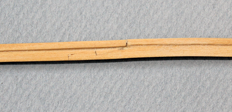
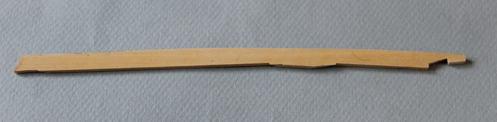
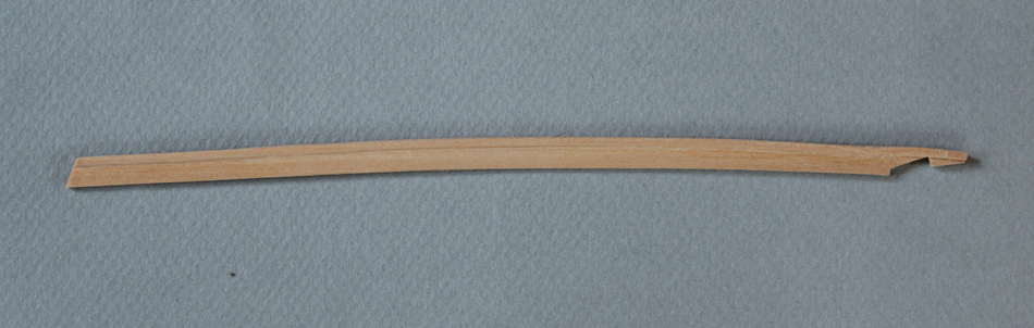
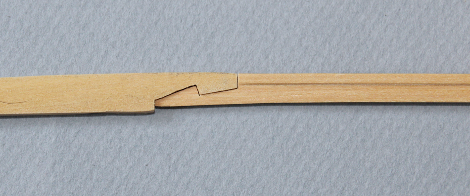
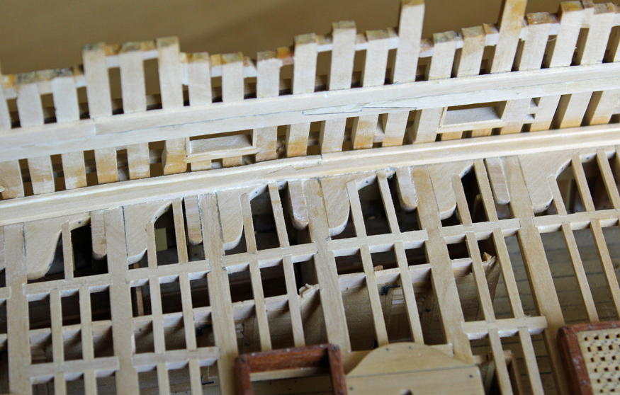
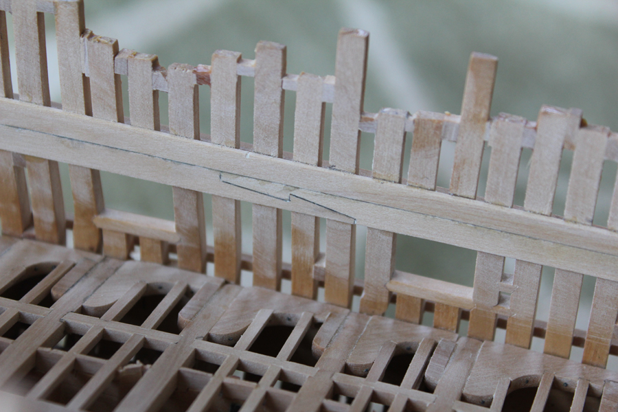
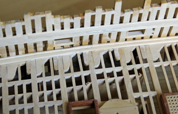
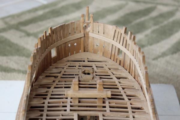
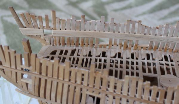
Not much progress to show over the last few weeks. Spring has finally arrived so the model does not get as much attention as it desires. I decided to install the string at the waist and the forecastle and quarter deck clamps. The string at the waist is a single row of planking with its lower surface forming the top of the gun port and its upper surface forming the top of the bulwark. It continues fore as the forecastle clamp and aft as the lower quarter deck clamp. Hook scarves are used throughout. The apparent decorative element at the fore end of the quarter deck clamp will actually be used to help lock in the spirketing. The upper quarter deck clamp has simple butt joints. In the pictures is appears that the lower edge of the string overhangs the gun port. It actually is flush with the top of the port. I encountered two problems. First, I measured the height of the clamp at the stem incorrectly and had to replace it. On the picture you can see a faint pencil line indicating where the clamp was originally positioned. The second problem has the potential to be more serious. I have two rows of planking with the top edge just coming up to the bottom of the aft port opening. David's layout shows the planking runs above the level of the port with a chock connecting the planks fore and aft of the port. At this point it is too late to change the port. I think I measured the port height off David's mylar and the clamp height off the NMM plans. Hopefully it will all work out OK. The key is that the top of the opening is below the top of the deck beams.

-
There is nothing magic about setting only the aft cant frames and then moving to the hawse timbers. The large area of open real estate simply makes it easier to fair the inside of the hull at the extremes. Beautiful work.
-
Those stanchions are incredible. I will definitely refer to your technique when I eventually get to this point.
-
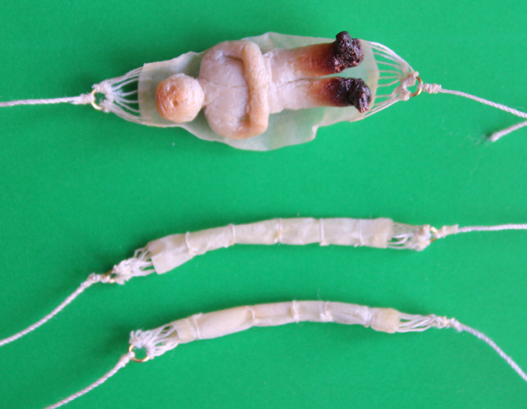
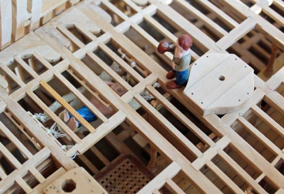
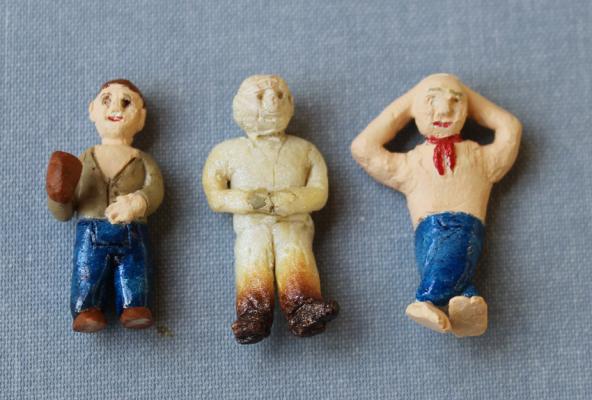
Robin, you are absolutely right. They are pretty clunky looking. I am not one to put figures on a model. And as you pointed out, my sculpting skills leave a lot to be desired. My intention is to use only the reclining figure. The hammock is under two decks and will barely be seen. This location was deliberately chosen for that very reason. Please keep in mind that the size of these creatures is 1 3/8", so in real life they look much better than in the photo. Druxey, they were fun but illustrate why I model ships with minimal decoration. Greg, I can only hope to achieve your skill. David, the figures really put the scale of the ship into perspective but one figure is plenty. The joinery is already busy looking and a painted figure detracts from the woodworking, unlike on a completely planked ship where figures could complement the scene. Remco, it is amazing how difficult sculpting is. Someday I hope to concentrate on learing this skill but with only a few hours of modeling time a week I would rather work on the build.
-
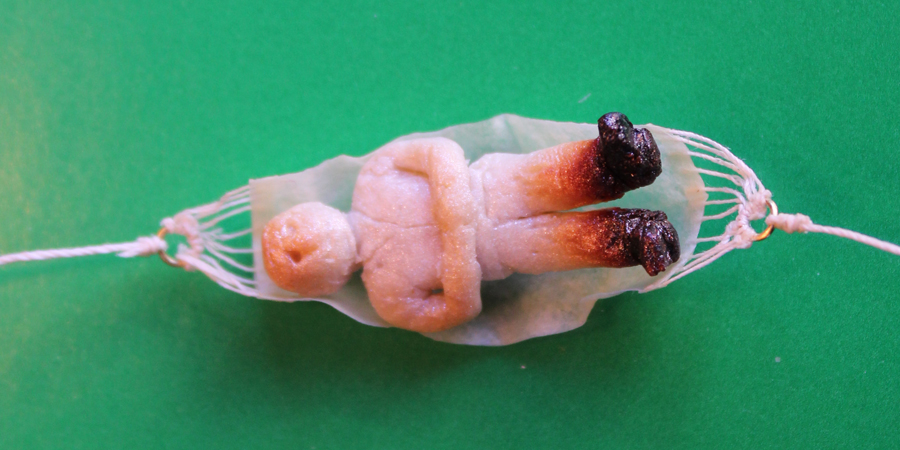
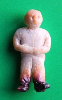
I was never happy with Mr. Crispy Toes so I have made two new crew members. Small items, like the head and feet, were added after the torso was baked and then epoxied in place. The captain has prohibitted drinking in bed so I have my sailor sleeping with his hands behind his head. His buddy up top is holding a mug of ale.


-
Danny, I'll keep that hint in mind for the future. David, Mark, Michael thanks for looking in. Grant, all I kept thinking was how pathetic my one sailor looked compared with Doris's masterpieces. Later in the week I will add some details and paint. It looks better in real life than in the pictures but I may end up throwing him out and starting over if I am not satisfied with the end result. One thing I learned from this is to add small pieces (like feet) after the main body has been baked.
-
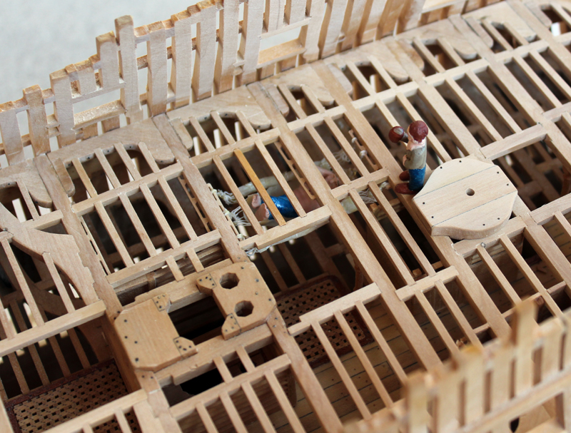
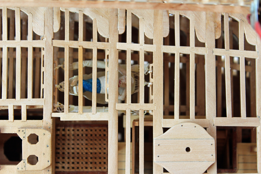
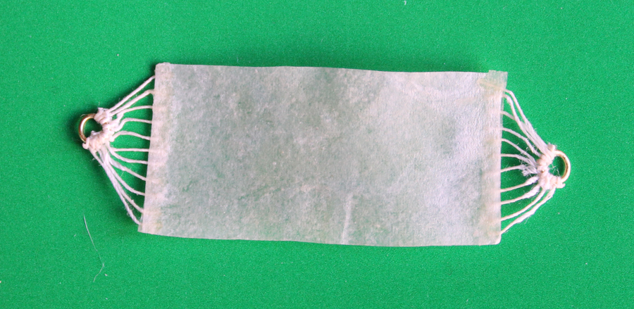
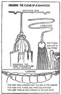
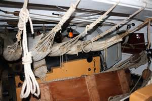
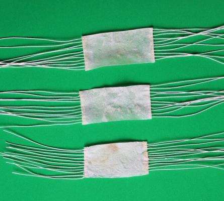
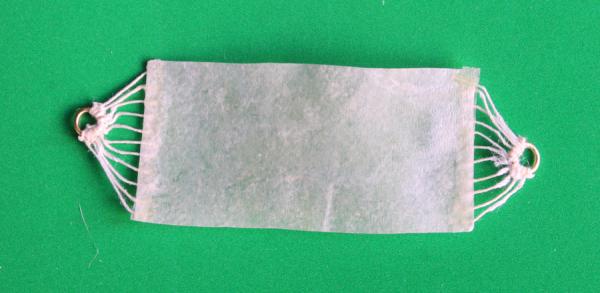
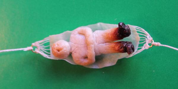
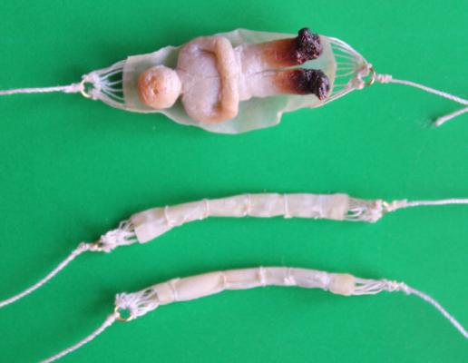
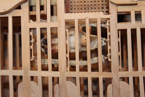
OK, here we go with my interpretation of hammocks. Remco, I'm glad you are so far ahead of me so I don't embarrass myself attempting to duplicate your hammocks! First of all, I had no idea how the hammocks were designed. I found some pictures and sketches on the web to guide me. The hammocks are a regulation six feet long. I made mine three feet wide. Multiple cords (nettles) are sewn to the hammock and end in a ring. A lanyard then extends from the ring to the batten and then doubles back and is secured proximal to the ring. The right hand picture actually shows the hammock suspended from battens on the far side of the beam. The drawing in TFFM suggests they are suspended from the near side of the beam, so I used that interpretation. The next problem was materials. After some experimentation, I decided to use 2 ply of Kleenex impregnated with dilute yellow glue. The look was initially too shiny but after rewetting a few times and rubbing them down the final look is one of used canvas. I added ten nettles per side and secured them on the underside with an additional single ply strip of Kleenex. I used an unblackened brass ring to secure the nettles. I was afraid the blackening would rub off with all of the handling. I used the finest thread I had available (No. 100 Cordonet) for the nettles, but they are too heavy appearing. The lanyard is No.30 Cordonet. Now comes the "interesting" part. I like to think I am a pretty decent surgeon. Surgery is easy compared to sculpting. I made my sailor out of Sculpy. He is 5'6" tall. When I baked him he got a little burnt. I guess I won't have to paint any brown shoes on him. I am not home this week and so he won't be painted until next week. I moistened one of the hammocks and wrapped it around my sailor so it would look like he was laying in the hammock. The other two hammocks will be shown trussed. These were also moistened to that they could be folded. After the folds had dried, the hammocks were trussed. I tried to hang the hammocks as depicted in the drawing but simply could not get the thread tied proximal to the ring. So I tied the hammocks off to the batten. I removed two ledges to gain access to the area. They have been temporarily replaced for the picture.
-
Sadly, Druxey, you have got me thinking. Should the sailor have a mug of grog while he is lying in his hammock? Or reading his Kindle?