HOLIDAY DONATION DRIVE - SUPPORT MSW - DO YOUR PART TO KEEP THIS GREAT FORUM GOING!
×

tlevine
-
Posts
2,032 -
Joined
-
Last visited
Content Type
Profiles
Forums
Gallery
Events
Everything posted by tlevine
-
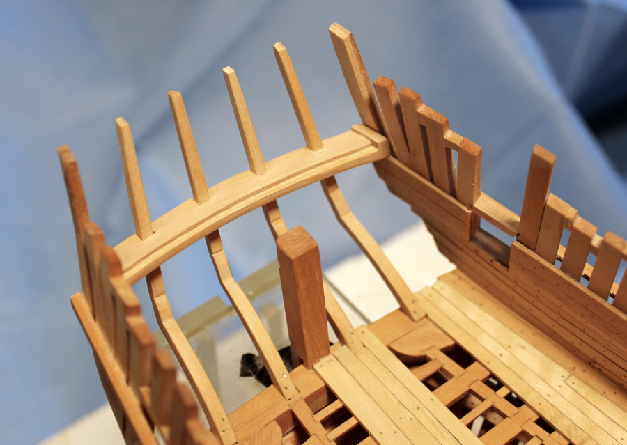
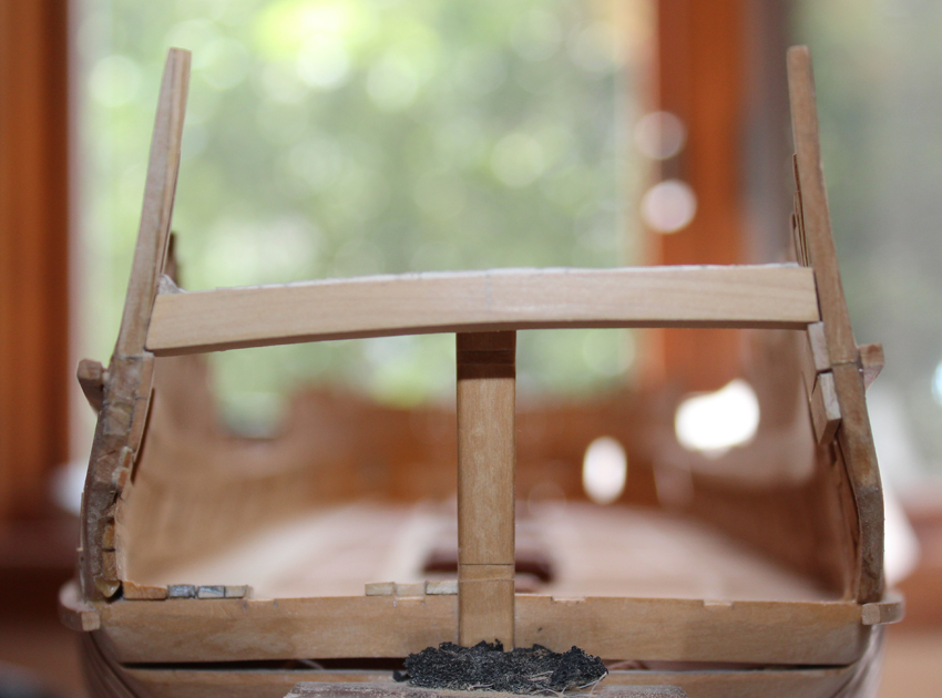
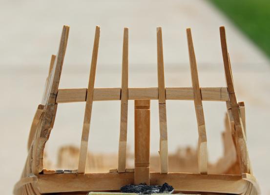
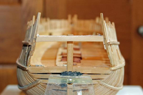
 Druxey, thank you for your astute observation. When I saw the photo I went back and measured everything...again. The angle of the photo is part of the problem; the difference is actually barely noticeable. The position of the quarter deck transom is correct. The starboard end of the wing transom is lower than the port, giving the illusion that the quarter deck transom is uneven.
 -
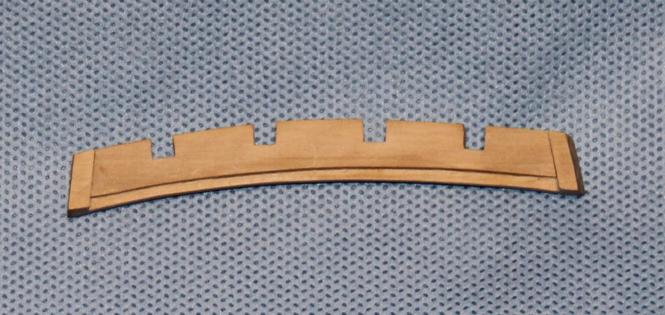
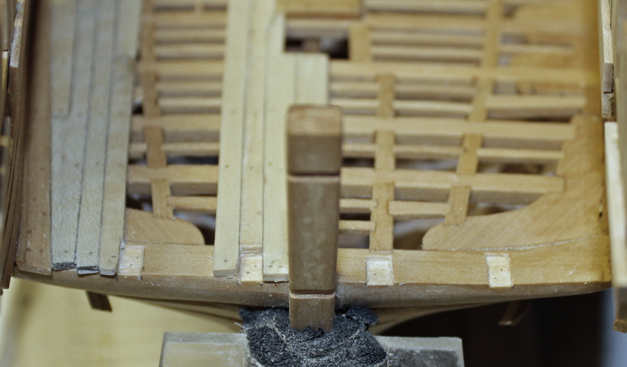
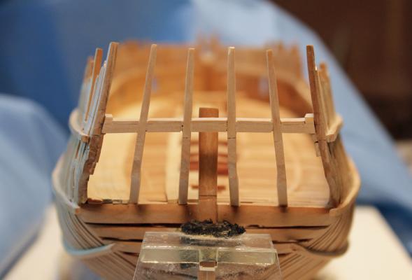
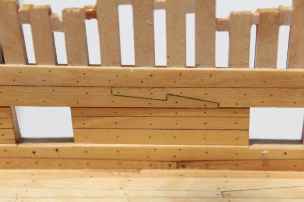
Now that I was happy with the elevation of the quarter deck clamp, it was time to finish the quarter deck transom. The middle and inner counter timbers fit into slots on the aft end of the transom. The slot has to be cut at an angle fore and aft as well at side to side because of the shape and slope of the counter timber. The upper face of the transom is shaped to the curve of the quarter deck beams. A rabbet is cut into the fore end to accept the deck planking. The extensions on the ends of the transom are for the waterways. Everything was going well until I discovered that I had cut the top of the transom too thin. Luckily, I cut the rabbet to the correct thickness and so added a thin layer of wood to build up the aft portion of the transom. This line can be seen looking from the stern but will be covered up by the stern planking. The last two pictures show everything glued up and brass bolts inserted into the feet of the counter timbers. I will touch-up these bolts with black paint after final sanding.

-
Danny, scary that we had the same issue. After I discovered the problem I simply walked away and did nothing on her until the next day. Of course, then you are second guessing yourself. I remeasured both sides bow to stern and found no other issues other than a slight rise at the stem, which will be dealt with when I frame the forecastle deck. Well, Druxey, I guess you simply can never go on holiday again!
-
Thanks for the encouragement, guys. Hopefully this will be my last close call!
-
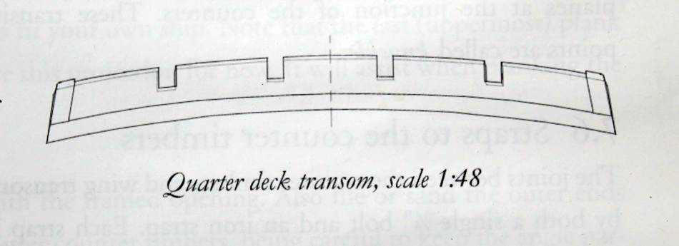
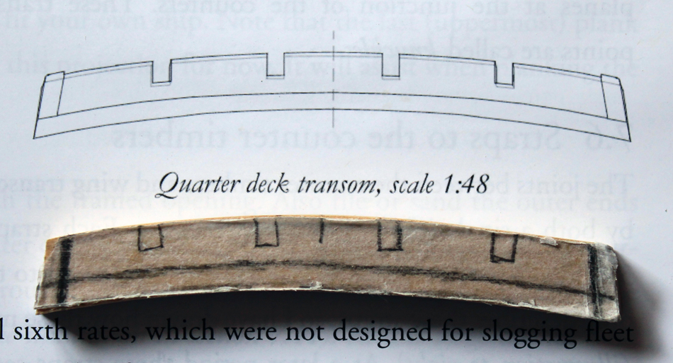
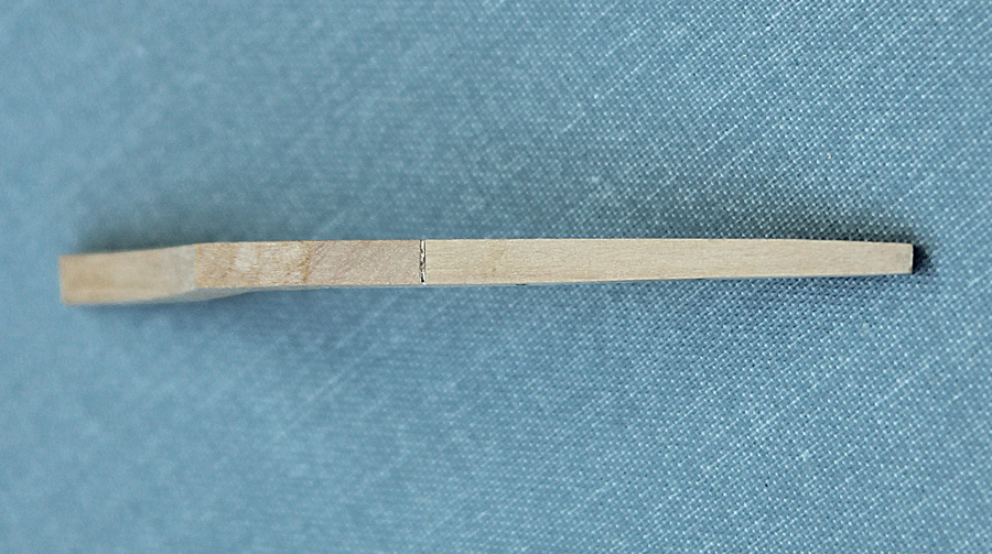
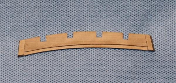
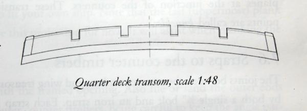
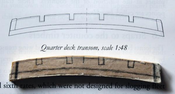
Thanks Ben. And thanks everyone for the likes as well. The next step was to make the quarter deck transom. The first photo is a drawing of the transom from TFFM. I used it as a starting point to develop a template, as seen in the second photo. This piece is made extra thick to accommodate the roundup of the deck and the waterways. And then disaster struck! As is obvious from the photo, the quarter deck clamps are not level. I went back and remeasured everything. Luckily the port elevation was correct so I only had to adjust two planks rather than the entire run of planking on the finished side.

-
Thanks for the encouragement, Greg. David, why don't you post pictures of something you have completed?
-
May I suggest two tools for cutting the scarfs...chisels and a hobby-sized miter saw. Actually three tools as you will need a way to sharpen the chisels as they become dull. Make a bill of materials for the thicknesses of wood you will need for the keel, deadwood, transoms and frames. Then carry your barrel staves to a local cabinet maker and let them cut the wood to the correct thicknesses. Although you will need a table saw at some point, this is relatively inexpensive and will allow you to get building sooner.
-
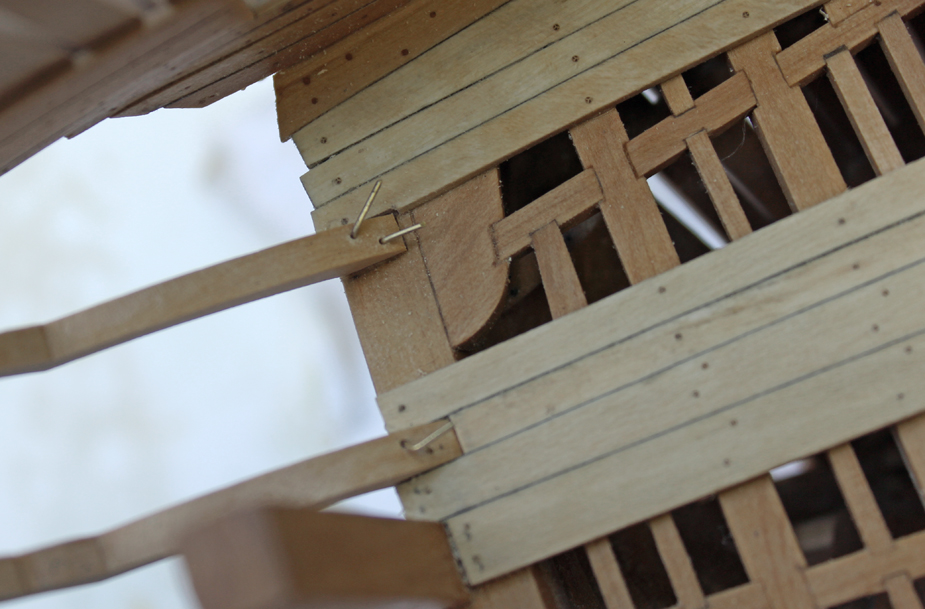
On the actual ship there would be iron straps extending down from the counter timbers and on to the inner surfaces of the lower transoms. The TFFM construction sequence shows the counter timbers and quarter deck transom installed prior to building the upper deck. I chose not to follow this sequence because I was afraid of damaging the stern framing during construction of the upper deck. The downside is that It is now impossible for me to install these straps. My compromise will be to insert bolts into the holes that I am using to position the counter timbers on the wing transom. In retrospect, I should have fabricated the counter timbers, along with their straps before the deck was constructed and then left the straps attached to the lower transoms so that I could build the upper deck around them. I am still happy that I left the stern open while building the upper deck as it gave me much better access to the inner hull.
-
Looking good, Bob. Well worth the wait. Now stop playing with those grandchildren and get back to making more sawdust!
-
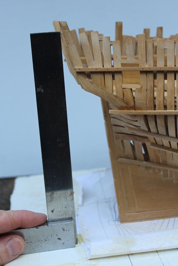
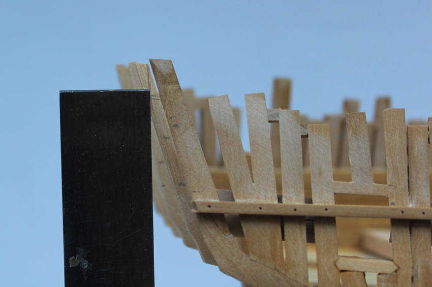
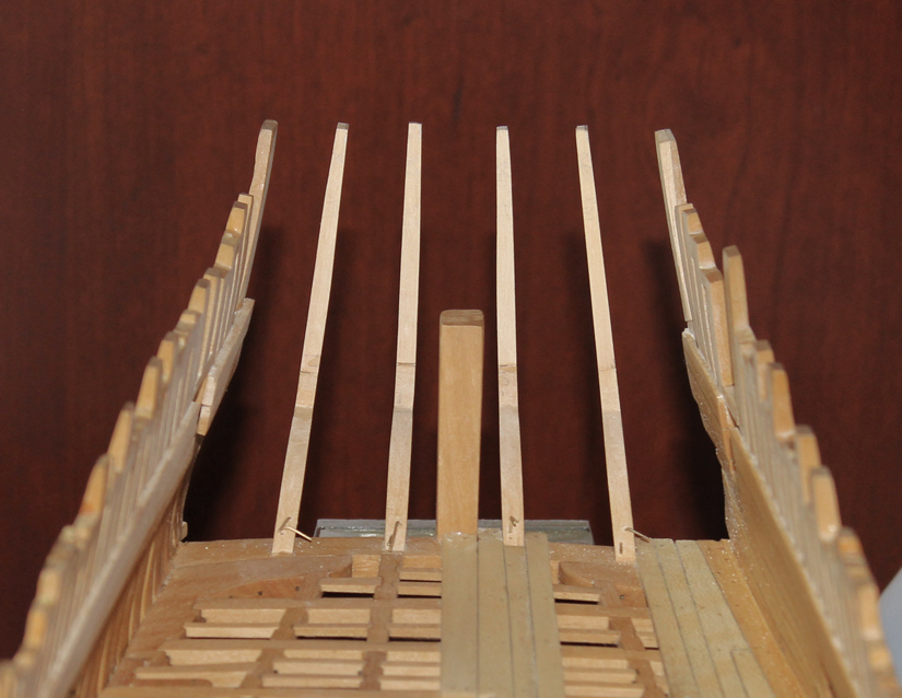
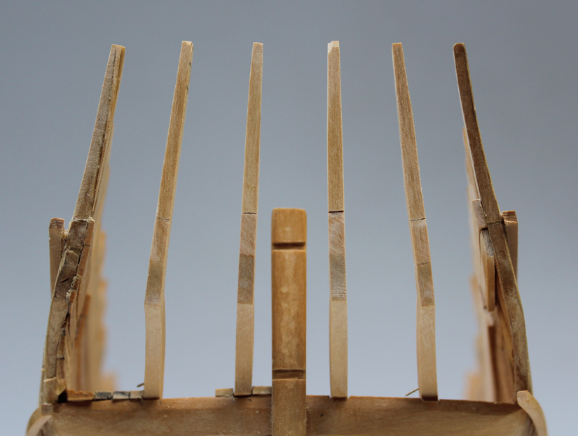
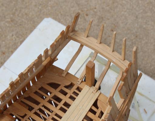
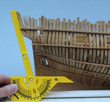
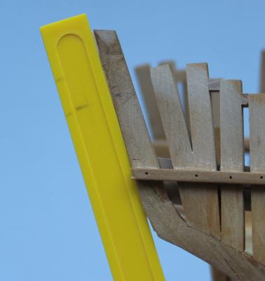
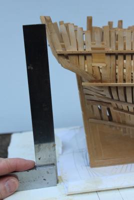
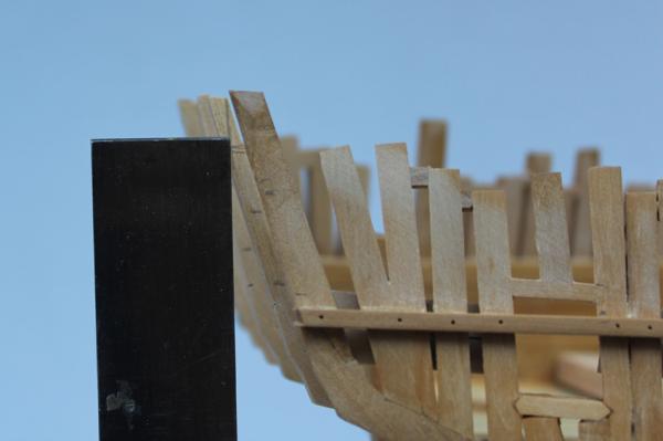
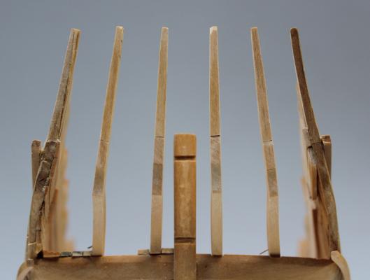
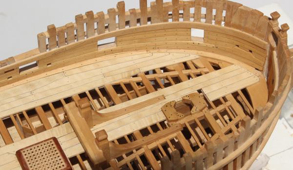
Now it is time to move on to the counter timbers. There are a pair of middle and inner counter timbers. These timbers provide the framing for the stern and frame the stern lights. They are canted towards the midline but the inner timbers have a different angle from the middle ones to allow for a pleasing appearance to the counter. This is one of those things that is harder to describe than to illustrate; it becomes obvious as the framing is erected. They are each made of two parts, just as the outer timbers were, with a scarf joint. They decrease in thickness from bottom to top. I made a rabbet in the transom to allow for a more secure seat for the timbers. In order to do this, an additional 1" was added to the foot of the timber to compensate for the rabbet. One of the tricky points is getting the angle of the counter timbers correct. I accomplished this two ways. First, I temporarily glued the timbers in place. (I think I glued and unglued these pieces 4 times during the construction process.) Next, I measured the angle of the outer counter timbers with a protractor. Although there is a curvature to the stern, the angle of the counter timbers remains constant. This let me set the angle of the rest of the counter timbers. To double check my work I drew a line on the plans from the baseline to the aft end of the timbers at the top rail and at the top of the quarter deck beams. This height was then measured on the counter timbers. I did this by wrapping an angle iron with masking tape and drawing the points on to the tape. The timbers were raised and adjusted to get equal distances between them at the lights. Later on I discovered that the rabbet for the inner timbers were not equidistant from the midline. The error is approximately 1 mm (real measurement). This is the disadvantage of the rabbet... I was not able to correct this error without damaging the transom and so left it alone.


-
Pete, John and Ben, thanks for your comments. Danny and Greg, the striations were trivial in the unfinished wood. My only option was to rip out all the decking. Because the cannons will cause a visual break-up of the deck, I decided to leave it alone. I will be very careful with holly in the future. Danny, I have some holly from HobbyMill that is very white but I went with this older stock because it had a more muted tone. The stern is a lot of fun (not!). Hope to have some pictures by the end of the week. Danny, several years ago I actually abandoned a build (Amati's 1:60 Prince) because I could not figure out the headworks. I'm past that now but every time I walk into the living room that model is there to remind me how I need to keep improving my skills.
-
Contact cement works very well in these situations where you have two dissimilar materials to join. Apply a tiny bit to the pintle/gudgeon and to the model. Let dry according to the directions and then mount the hardware. Just remember, you only have one try with contact cement. The advantage is you do not have to worry about glue seepage.
-
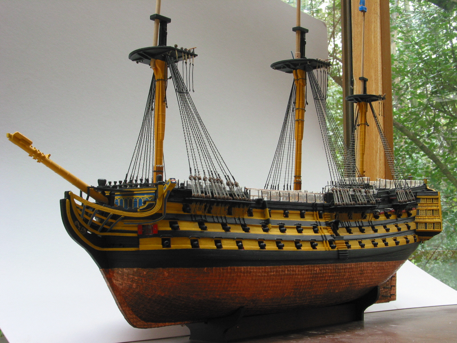
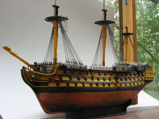
As several people have already stated, this is a hobby that balances historical accuracy and aesthetics. Victory is the only ship I have modeled that is painted. Although I originally intended to leave it natural, it "spoke to me" and informed me that it needed to be painted. This also gave me the opportunity to learn a new skill, airbrushing. I have added my best picture showing the run of the wales and gunports and how they do not follow the ochre striping. Good luck with your decision.
-
Thanks everybody for the encouragement and thank you for all the likes. I have started framing the stern. This is definitely one of the more difficult parts of the build. I hope to have something to post next week.
-
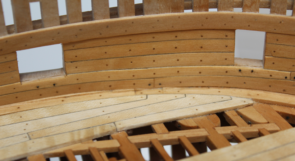
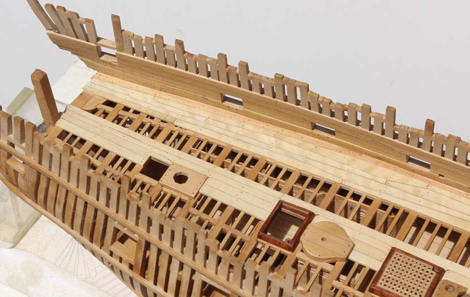
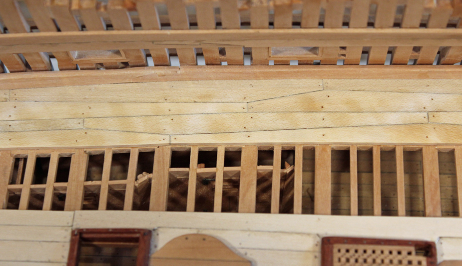
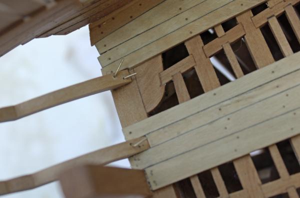
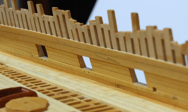
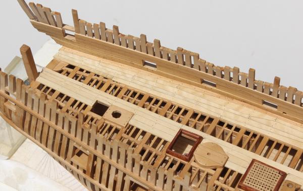
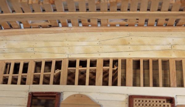
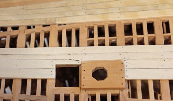
The spirketting and the quickwork have been installed. The spirketting is installed top and butt fashion, just like the outer rows of deck planking. It is 3" thick and the top edge of the upper row is champhered . The quick work is 2" thick and extends to the edge of the sill lining. I have not finalized the size of the hawse holes yet, so this area is not finished. Both the quickwork and the spirketting are treenailed to every frame. There is a single bolt at the butts and two bolts under each gun port. I was unhappy with the appearance of the bolts and so removed as many as I could without damaging the planking. I dyed some treenails with archival ink and used them instead of blackened brass for the bolts. The appearance is much cleaner, as can be seen in the photos. Compare the appearance of the brass with the dyed wood. Unfortunately, the rest of the brass bolts are in for keeps. I then applied a coat of Watco's, let it soak in for 30' and wiped everything down. The next day I sanded it with 600 grit and put on a second very thin coat of finish. The striations in the holly decking are in the wood and did not sand or scrape out. The lighting was poor so I did not have the opportunity to take before and after the finish pictures.

-
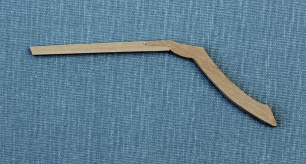
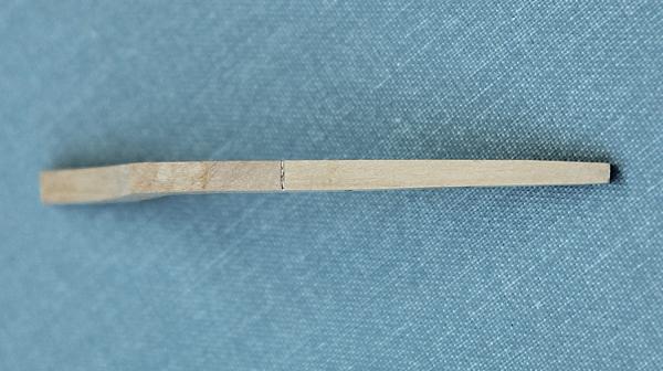
Take a peek at page one of my build log (link below my signature). I used 11 strakes of planking and I spiled them...no lateral bending. Look at where the fore end of the garboard strake terminates. If it rises up into the stem then the fore ends of the rest of the strakes will be too narrow. A good exercise would be to draw in the line of planking on the bulkheads. Do not let the width of any of the strakes get narrower than 50% at the stem. Then, make a template for the garboard strake based on the lowest line you have drawn in. You will end up with a strake that is shaped more like your upper drawing that terminates just anterior to the keel scarf.
- 132 replies
-
- 2
-

-
- 18th century longboat
- model shipways
- (and 1 more)
-
Thanks for the heads-up Danny. One of the beauties of your build is being alerted to all the potential problems (long) before I encounter them.
-
I used Testor's reflectance reducer to topcoat my friezes. There has been no yellowing after a year.
- 109 replies
-
- 1
-
-
- 18th century longboat
- model shipways
- (and 1 more)
-
Let's see. Fiberoptic headlight with Xenon light source. OR light. Where are the fiberoptic telescope photos inside the hull?
-
Are you planning on edge-bending the planks or spiling them? If you are using basswood, edge bending will work. Castillo is much more difficult to edge-bend, even with these thin planks. If you are planning in spiling them you will need to plan on wider planks so that they can be fit in place.
-
Pete, Ben, Greg and John thanks for support. I hope to get a little modeling time this weekend but I also have two water gardens that need cleaning. Maybe it will rain and I'll be forced to stay inside!
-
Ed and David, thanks for your comments. Mike, the anchor stock planking gives extra strength to the decking. It is also used in some of the ceiling planking as well as the wales for the same reason. See page 6 of the log.
-
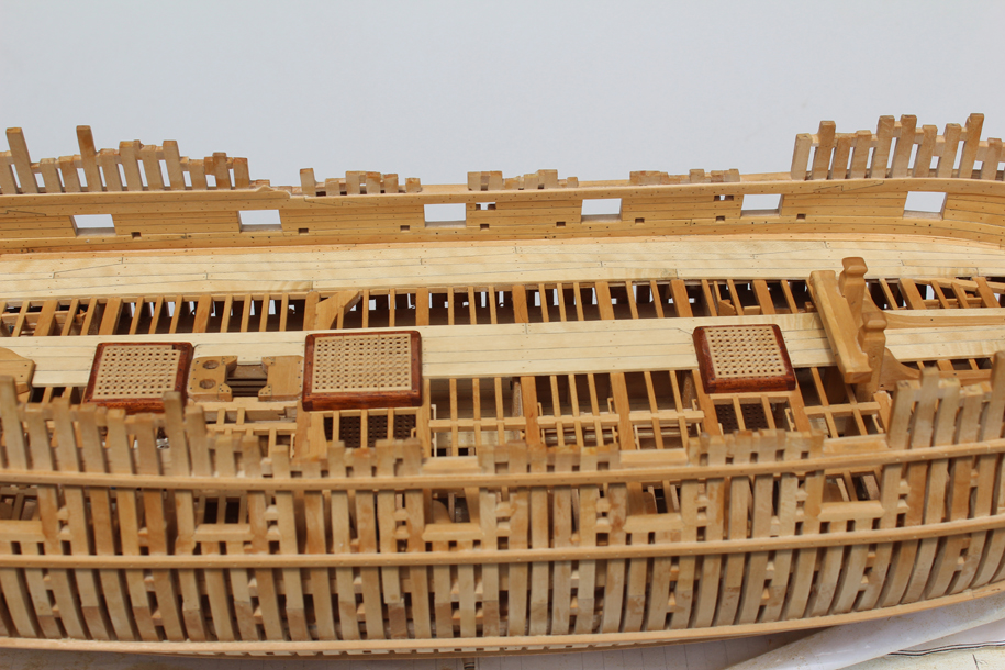
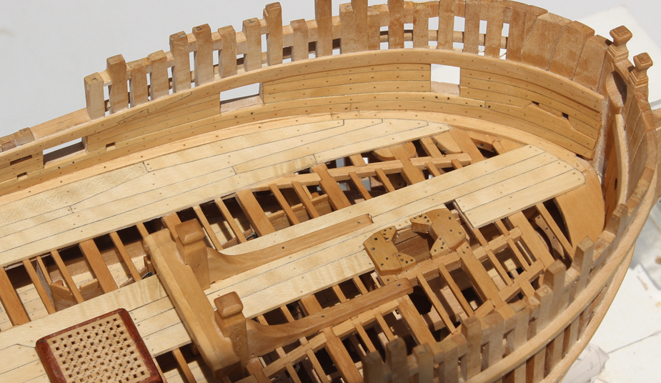
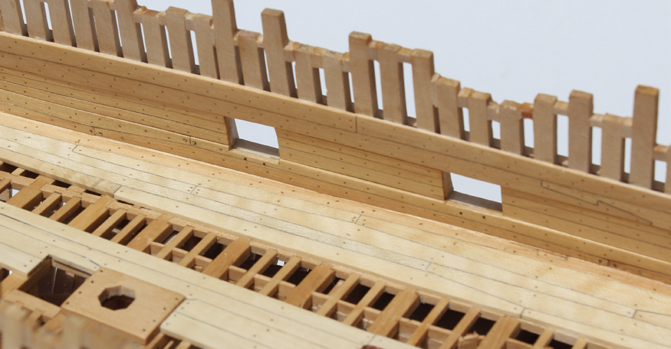
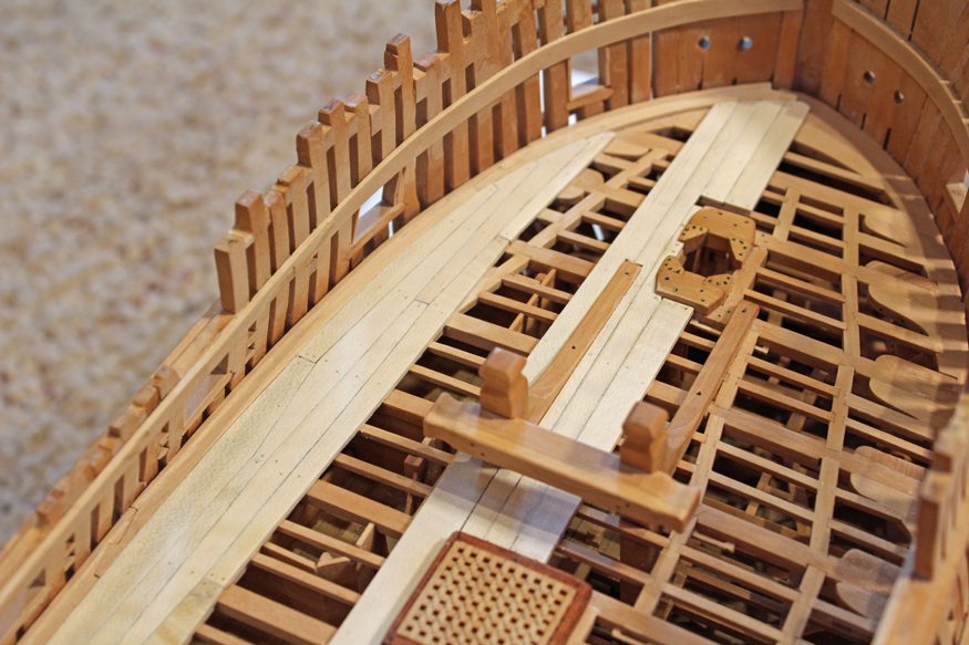
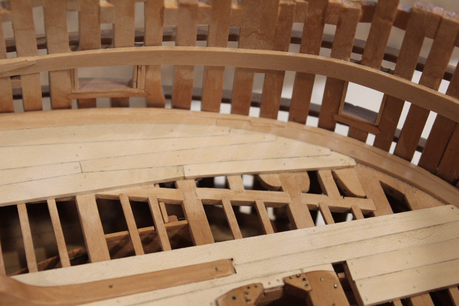
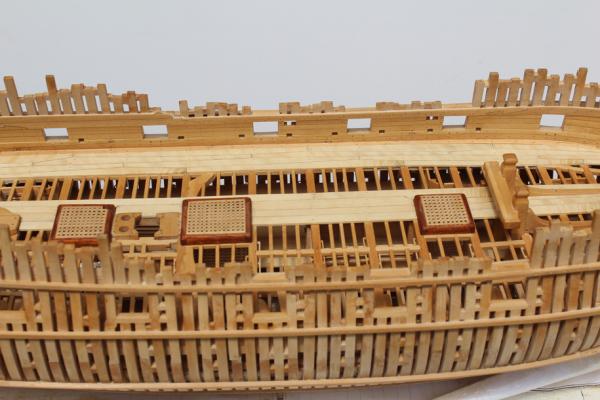
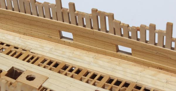
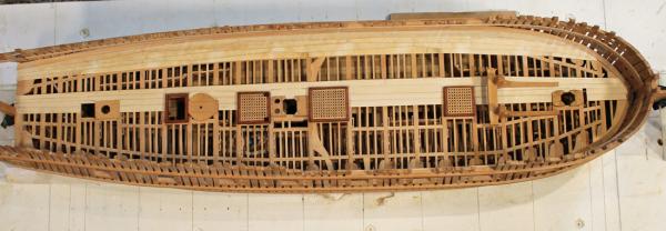
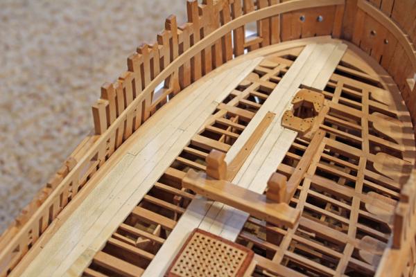
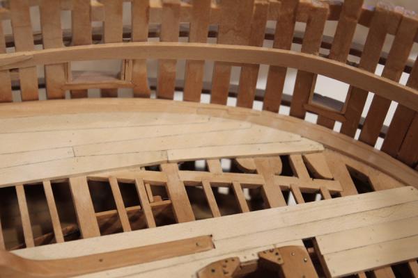
The upper deck planking has been installed and the first bit of sanding is complete. It still needs more scraping and find sanding. I used 3" holly for the planking throughout. The binding strake would have been inset into the deck beams but since that detail is not visible I do not model it. After looking at a lot of models, I decided to only plank the port side and the midline plank. I wanted to be able to look into the lower deck cabins and so I only installed decking between the binding strake and the midline and the four outside strakes. The central planks are fairly straightforward. The open area in front of the foremast step for the bowsprit step. The plank located by the well has not been glued in so that can be removed during installation of the bitts. The plank edges were "caulked" with a pencil. The treenails are bamboo, drawn down to a #77 drill and inserted into a #76 hole. I prefer to pressure fit these rather than use glue. The finish will bind them all together. The blotchy color on the pictures is not real. I had just washed the deck off for the pictures and did not give the wood sufficient time to dry. Compare the color contrast between the inner and outer planking. This all came from the same billet of holly.
-
Hannah was my first attempt at scratch building and I think it is a good choice. It is a small ship and there are no carvings or friezes. But if you are looking to build an exact copy of Hannah...choose another ship. This subject has been addressed in the various logs for Hannah but basically these plans are representative of what Hannah may have looked like. There are no as-built plans. If it matters to you, there is no below-decks detail.
- 83 replies
-
- 1
-
-
- sloop of war
- sloop
- (and 1 more)
-
The entire journal is a good read (even if you can't read Spanish). There is a great article on a boat made by a five year old with assistance from adults. the squid recipe looks tasty too.