HOLIDAY DONATION DRIVE - SUPPORT MSW - DO YOUR PART TO KEEP THIS GREAT FORUM GOING! (Only 13 donations so far - C'mon guys!)
×

tlevine
-
Posts
2,032 -
Joined
-
Last visited
Content Type
Profiles
Forums
Gallery
Events
Everything posted by tlevine
-
 Thanks, Ben.
 -
Great work on the chock. This entire build is full of "I thought that would be harder" and "That was easier than it should have been". Be careful of the latter because half the time that means it wasn't done correctly (voice of experience).
-
18' Cutter by Maury S - Scale 1:48 - SMALL
tlevine replied to Maury S's topic in - Build logs for subjects built 1751 - 1800
Looks very nice. I had some glue seepage on the interior but was able to remove it with scalpel blades and sanding sticks. -
Thanks, Greg. I had a slight tear out on the inside port hawse hole so that will work out perfectly. I have a question... Are the openings parallel with the water line, tilt inboard or tilt outboard? I can see logical reasons for all three scenarios.
-
Thanks, David. Ben, it is about 1mm different. Sorry about switching to metric but in my line of work it is easier to visualize 1mm than 3/64". Greg, in David's book he stated that the holes were 10.5" and then talks about lining them later on. I assumed that the eventual diameter would be closer to 7-8". Am I wrong? I would prefer to have them at the correct final size before I start the upper works.
-
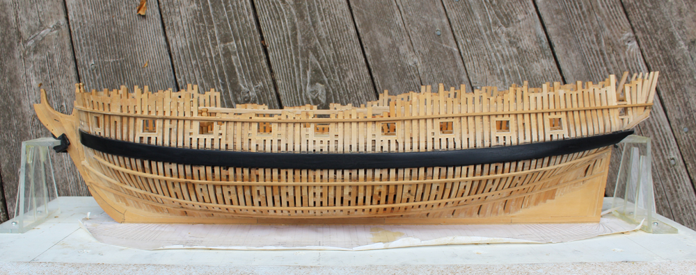
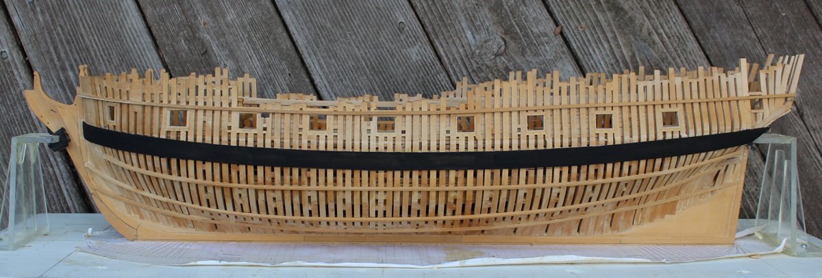
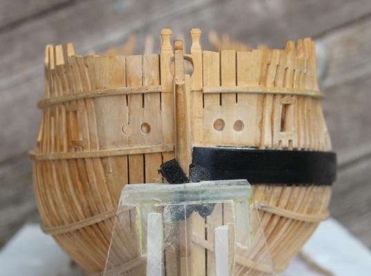
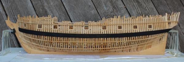
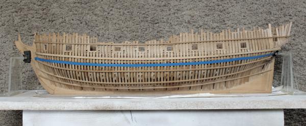
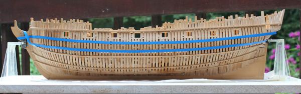
After six coats of paint I discovered that I did not camber the top of the wale sufficiently. There was also something about the finish that I did not like. So I sanded it all down and added the camber. I put on four coats of Model Master flat black enamel and sanded the last two coats with 1500 grit. This makes the plank seams and treenails a little more apparent and gives a luster to the wood without being shiny. Bolts at the butts were added after the picture was taken. The hawse holes were left undersized until now. They are 10.5" in diameter. I used the top of the wale as the base to run a compass along marking the center of the holes. On the starboard side I used the ribband. The holes were enlarged with a combination of drill bits, Swiss files and sandpaper wrapped around a dowel.

-
Thanks Harvey and Remco. Ben, those were rough-in hawse holes. Greg noticed the same problem. Pictures to follow. Dave, the measurements are approx. 8" x 29". I do not plan on masting her.
-
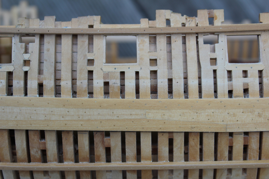
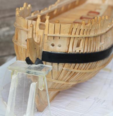
The planks of the main wale have been drilled for the bolts at the butts and the treenails have been installed. The bolts are 0.75" in diameter and the treenails are 1.25" in diameter. Although not quite to scale, I used a 77 bit for the bolts and a 75 for the treenails. I usually dry-fit the treenails, relying on the finish to hold them in place. However, I wanted some structural strength with these treenails so I drilled them deeper into the frames and dipped them in dilute glue to secure them. I realize no one will see them, but it only took a few hours and the added security is worth it. I wet the wale in the second photo to make the treenails stand out. Next came applying a black finish to the wale. I tried several approaches before making my final decision. I found an unopened bottle of Floquil hull black. This looked good but when I applied the Watco's finish it rubbed right off. Next I tried archival marker. Looked good but the length of time it took to apply tried my patience. Feiberg's leather dye also looked good and allowed the joint lines to be slightly more apparent but it bleeds into the wood and I was afraid of getting it onto the stem (even with masking). My winning choice was artist acrylic paint. This comes in a tube and can be diluted to the desired consistency. It applies nicely and there was no concern about ruining the stem. I was a little sloppy in getting paint on the frames when painting the edges of the wale but this will be covered with planking and so will not show. The photos show the first coat applied. I am up to 3 coats and will probably go with 3 more. In between coats I am sanding with 600 grit wet/dry sandpaper (used dry). Each subsequent coat is more dilute than the initial one. I have left the aft edge a little long for final shaping later. The bolts will be installed after the painting is completed.


-
18' Cutter by Maury S - Scale 1:48 - SMALL
tlevine replied to Maury S's topic in - Build logs for subjects built 1751 - 1800
Have fun with the cutter. As I recall, there was a problem with the top of the sheer. What are you going to use for the planking? We used holly at the seminar; it bends beautifully and is a nice contrast to the costello of the frame. -
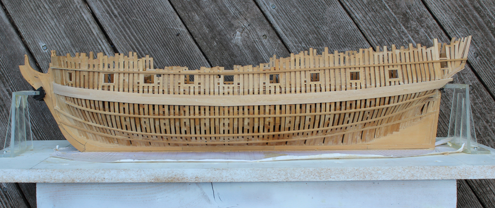
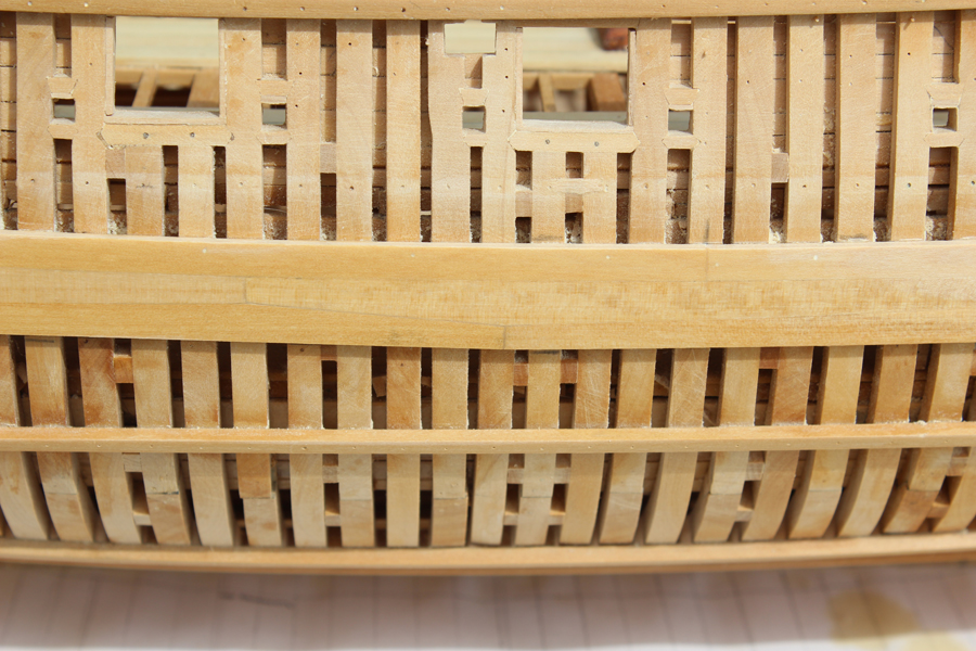
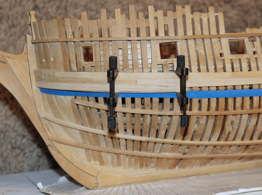
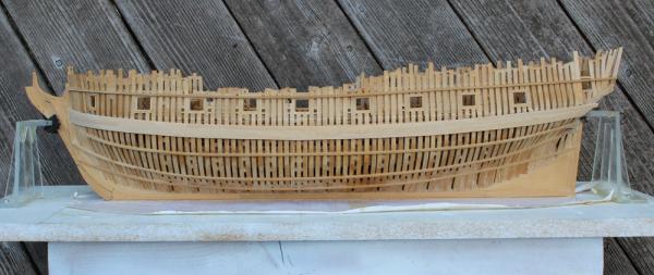
The three runs of planking that make up the main wale have been installed. As you can see, most of the joinery disappears after sanding. In the first picture I wet the wood to make the plank edges stand out. The next step will be to mark out and install the treenails. The slight rise at the fore end of the wale when looking head-on is not apparent when looking at the ship, so I am going to leave this be. I would cause far more damage if I tried to remove the wale in order to drop it 0.5 mm.


-
Looking fantastic as always. The run of planking looks fine. The slight color differences between the planks help delineate them so they are not just a sea of costello. Enjoy your treenailing.
-
Yes, Druxey, I tapered the fore end of the plank down to 3" to fit into the rabbet. Greg, the joinery essentially disappeared after sanding, much less planking. But like so much of this exercise, I know it was down correctly.
-
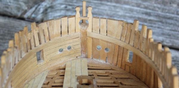
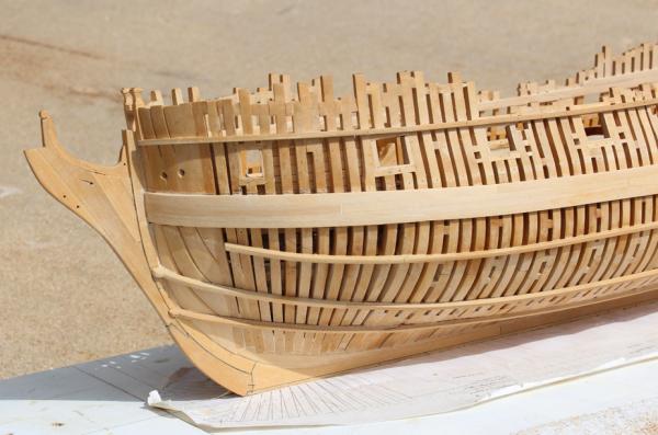
Thanks Ben and John. Michael, I am first making a template of the plank on card stock and then transferring the shape onto the wood. I cut it out on the Preac and make final adjustments on the ship. As you can also see on the photos, I have removed the upper ribband and the for part of the second as well. The rest will be removed as the planking continues.
-
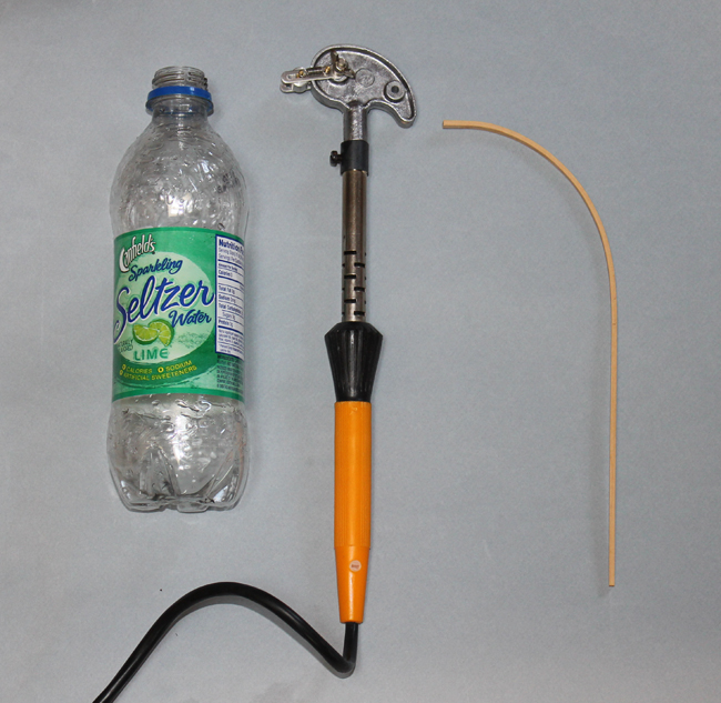
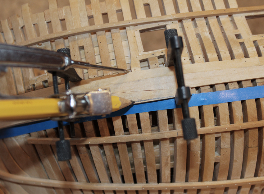
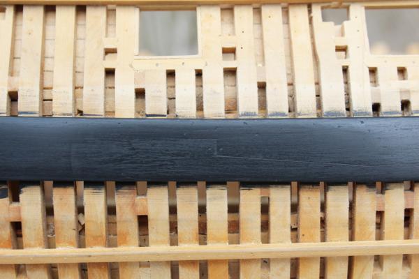
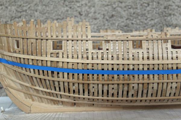
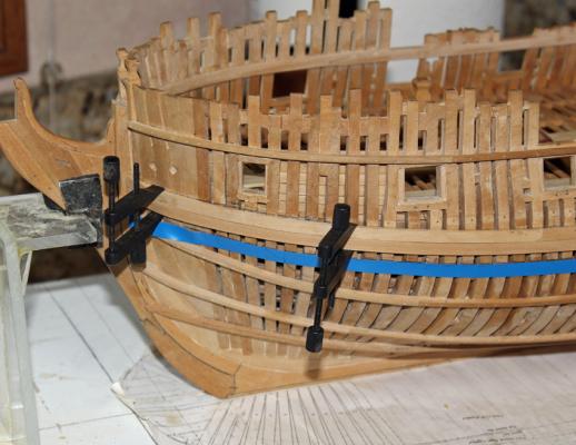
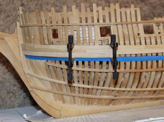
The main wale is composed of three strakes. The upper most is a straight board. The lower two interlock with anchor stock planking. The ends are all butt joints. Several of the planks have either severe bends or twists in them. My basic technique for plank bending if the bend is mild is to soak the wood and then clamp it into place, allowing it to dry. I will then final fit and glue into place. The bends at the bow are anything but mild. For these planks I soak them for a few hours and then use my ancient Aericopola plank bender to bend them. I over-bend them and then allow them to finish drying off the model. Then I final fit them and glue them into place. One trick I have learned is to leave extra length (1/2") on the bent end (the bow in this case). The plank bender will not work well at the end of the plank and the final result is usually a broken end. By leaving the extra length, the extreme end of the plank can be left straight, avoiding breakage. I use a 16 oz soda bottle because it is tall enough to soak a long length of wood and it does not waste too much water. Floating the wood in a pan of water results in one side staying much drier than the other. The plank shown is 0.95" thick and was bent in about five minutes. In the second photo the plank is offered to the hull without forcing. The first row of the wale has been installed. The lower tape is left for reference. The middle row of the wale planking has been installed. Since I plan on painting the wale I decided not to highlight the plank edge with paper or chamfering. You can see the saw-toothed appearance of the anchor stock planking in the second photo. For the lower row of planking I first fit the top of the plant to the middle plank. After I was happy with the fit I marked the lower edge with a compass and cut the plank down to the line.


-
Thanks everyone. The first strake of the main wale has been installed. I hope to finish it over the weekend. Pictures forthcoming.
-
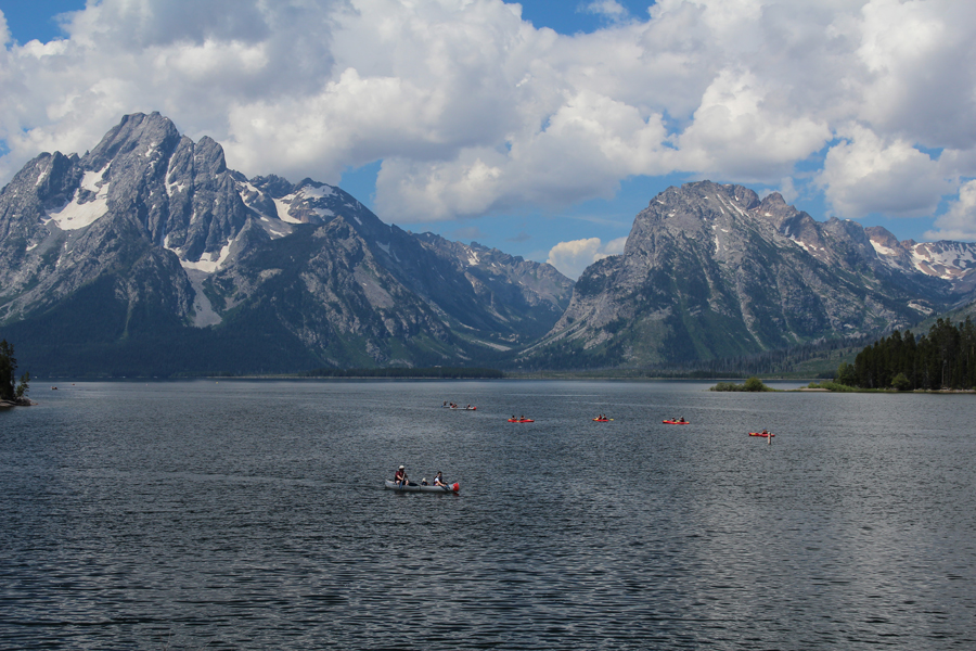
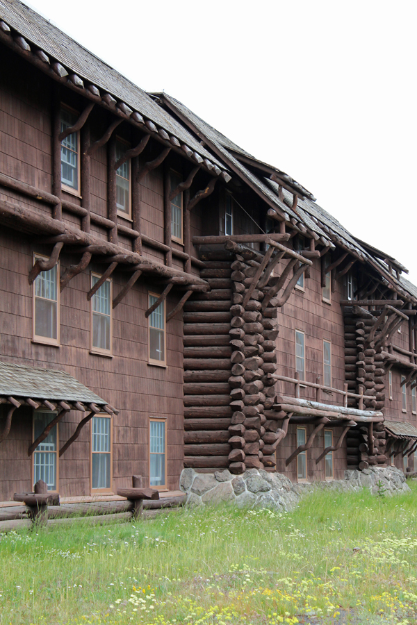
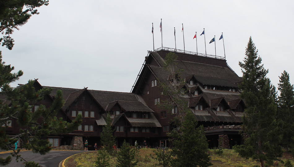
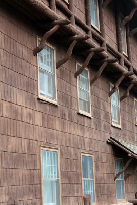
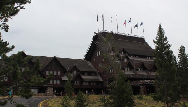
It has been a while since I have posted anything new...but I have an excuse. I was performing nautical research in the Tetons and Yellowstone. For you non-US folks, these are two national parks adjacent to each other in the Rocky Mountains. First I had to research the types of water craft used on Jackson Lake. This photo was taken from our campsite. We had rain and so drove up to Yellowstone. We had never seen Old Faithful and decided to act like tourists. There is a lovely grand hotel called the Yellowstone Inn that overlooks the geyser. It was built by the railroad in the '20's to promote travel in the West (which had to occur via rail since there were few passable roads). Walking back to the car I looked up under the eaves and saw...compass timbers! So much for the nautical research. The rest of the time was spent hiking and enjoying a phenomenal wildflower display.


-
Absolutely love it! A perfect example of how MSW turns a bunch of crazy ship modelers into a crazier bunch of ship modelers.
- 1,214 replies
-
- 5
-

-
- sloop
- kingfisher
- (and 1 more)
-
That is a pretty little ship. Not too complicated but with plenty of challenges. I usually do not like the clutter of sails but on this model they bring the ship to life. You have a hard decision ahead of you. I once quit modeling for five years because of a lack of motivation, although I would still visit the workshop several times a week.
- 290 replies
-
- 1
-
-
- confederacy
- frigate
- (and 1 more)
-
Thanks, Pete. Mike and Ben, I will make my final selections in the next few weeks. The first order of business will be to install the wales.
-
Mark, although I like the look of unsteamed pear, I find swiss pear too pink for my taste. I am going to cut some planks of pear, holly and pau marfin (in addition to costello) and see what I like best. David, I didn't say the paint was bought recently . It is left over from my Victory build so it must be at least 10 years old.
-
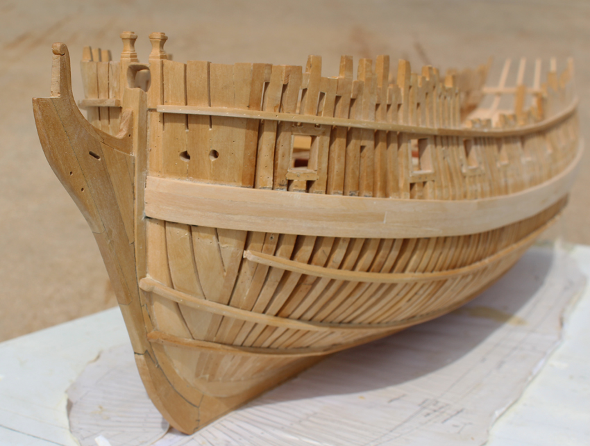
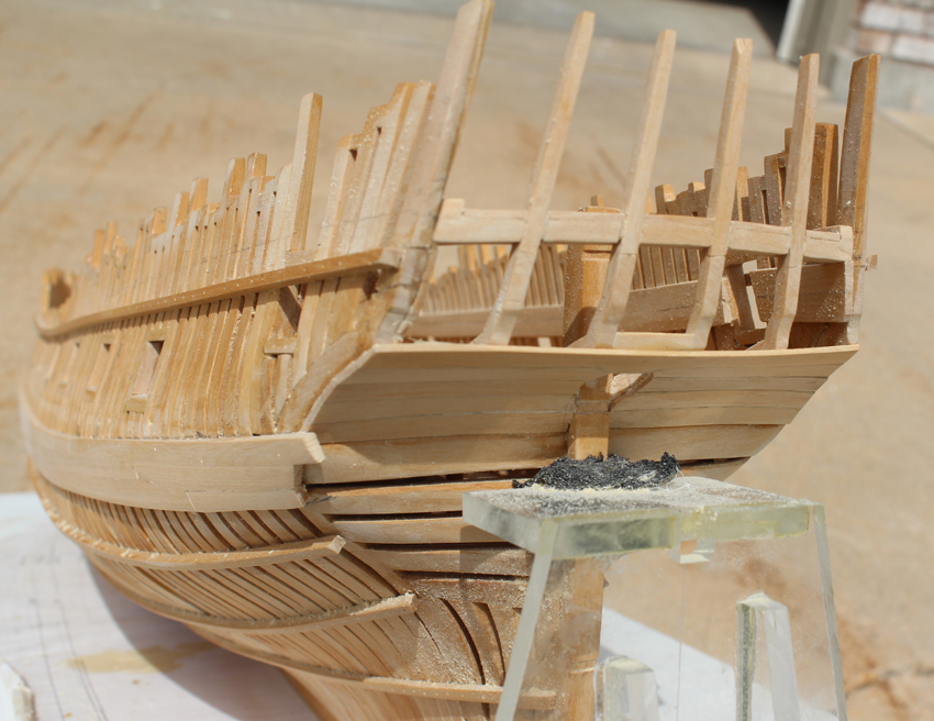
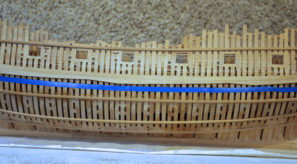
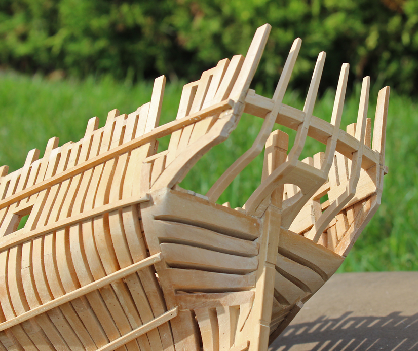
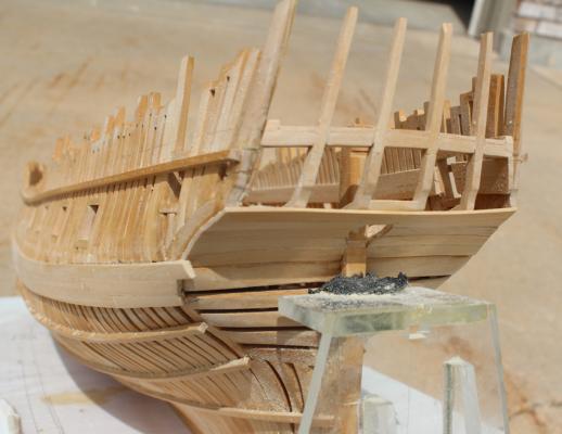
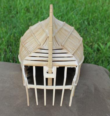
A belated thank you Remco. And thank you everyone for the likes. A little progress has been made. In order to fit the counter planks the ship had to be "launched" from its building board. This marks the first time I have removed it from its home since fairing the exterior of the hull over a year ago. No champagne was wasted in the launching but I did toast it with a little homebrewed IPA. I have also done a little more fairing of the lower transoms and cut off the aft ends of the ribbands. The lower counter was covered with five rows of planks. These are cut to shape rather than attempting to edge-bend them. The planking started next to the stern post and progressed outwards. The exact shape of the cut-out on the outermost plank will await fabrication of the rudder. There are a few points in every build where decisions need to be made which will impact everything else going forward. I am at one of those points. I have decided to attack at least some of the hull planking next. The decisions to make are: how much to plank, what materials to use and what finish to apply. I will be leaving the starboard side with ribbands and hairpins. The port side will be completely planked. The main wales will be castillo that will be colored black. I made test pieces using india ink, archival marker, ebony stain (oil and water based) and paint. Ink is very messy but dyes the wood well. I found the archival marker too time consuming but it does a good job of dying the wood. Regular marker will bleed with oil based finishes. The castillo is to dense to take up stain readily. I have opted to paint the wale black with Poly S model railroad color Engine Black. I used this same approach with Hannah. I am still uncertain about the rest of the planking. It boils down to aesthetics... Two colors vs. several. I am leaning towards only two colors but I'm a girl so I have the right to change my mind at any time. I measured the top and bottom of the wale from the plans and marked the points on the hull. I then ran a row of pin striping tape above and below these points and faired them to a smooth run of planking.


-
They look great. It took me a few tries as well before I was happy with the results.
-
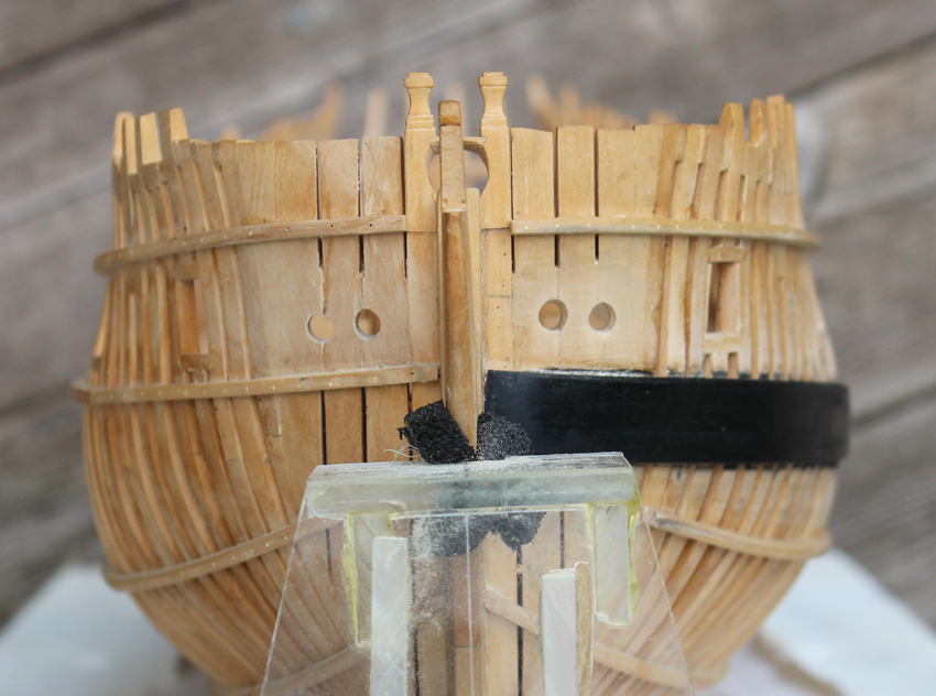
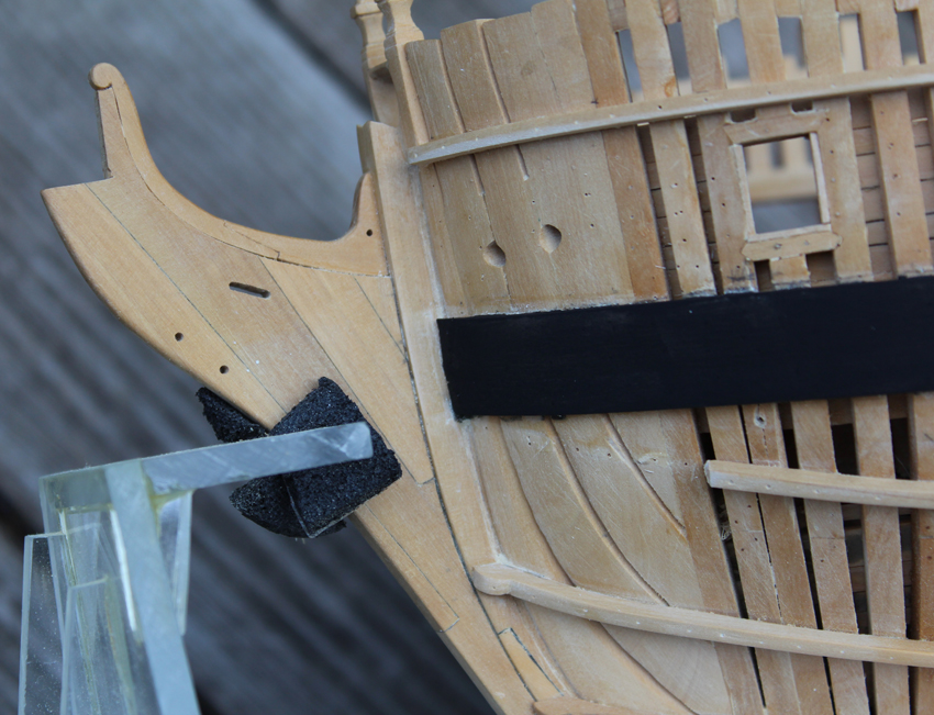
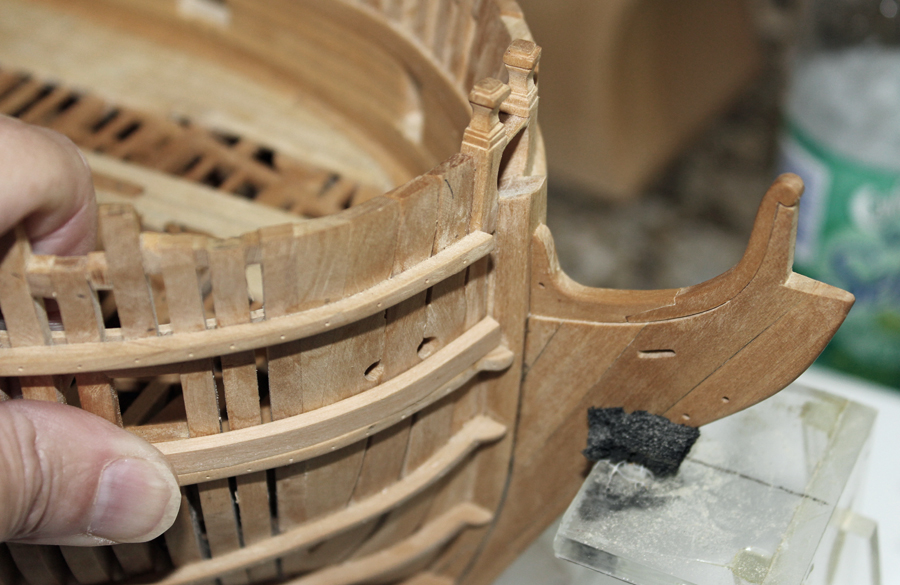
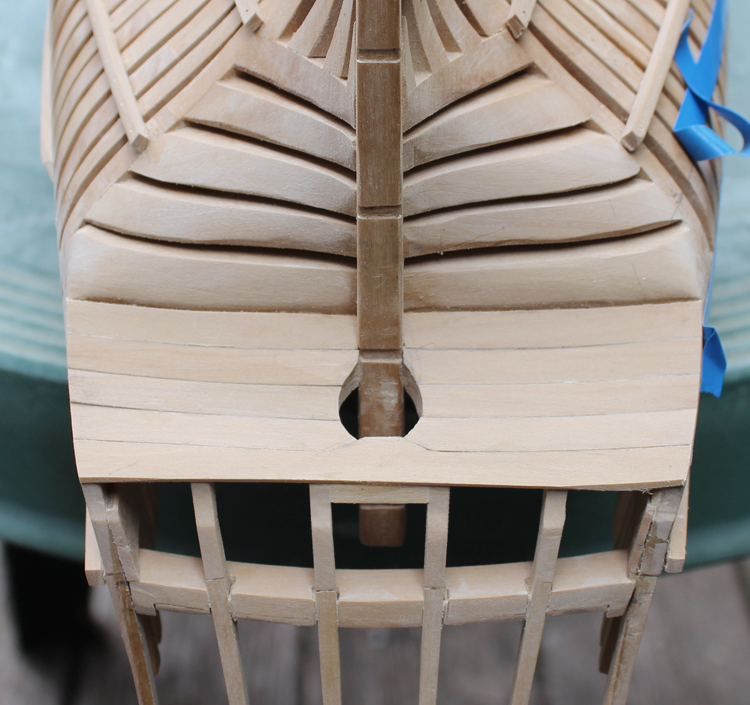
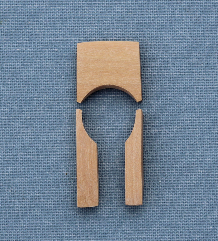
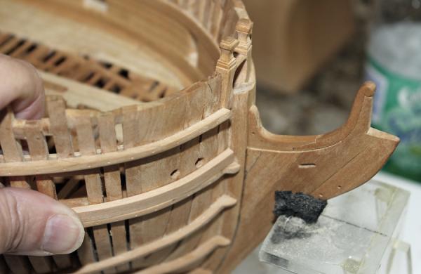
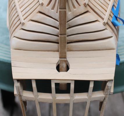
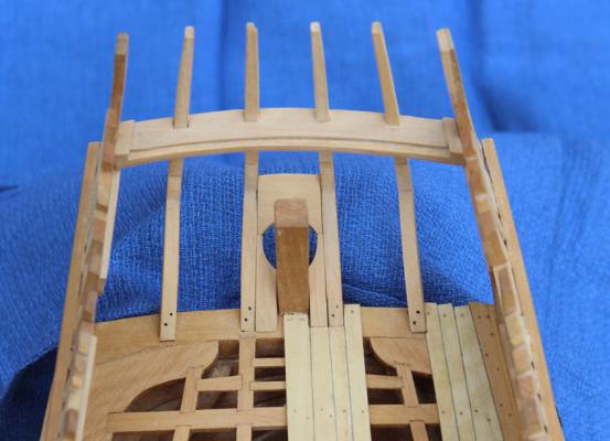
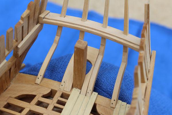
David, I made a template of the space between the inner counter timbers to give a general outline for the piece of wood to cut. Next, I sized the piece to fill the entire space between the timbers, cutting the opening for the stern timber. I made sure the wood was thick enough to accommodate the inner and outer curvatures. The opening for the rudder was drawn on the piece as were the cuts for intersection with the chock. After cutting away everything aft of this point I was able to make the hole for the rudder and install the side pieces. The chock was formed by careful fitting and refitting and refitting.
-
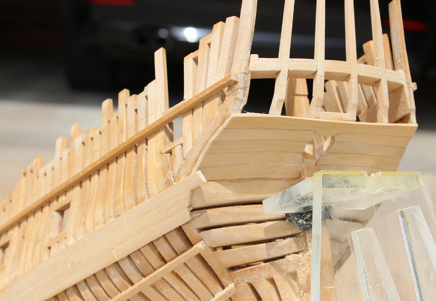
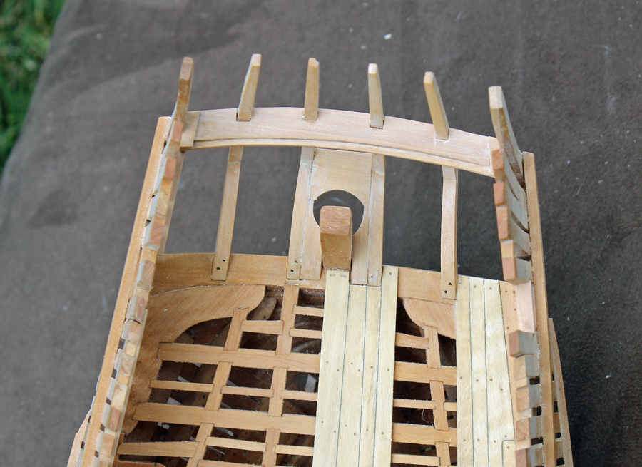
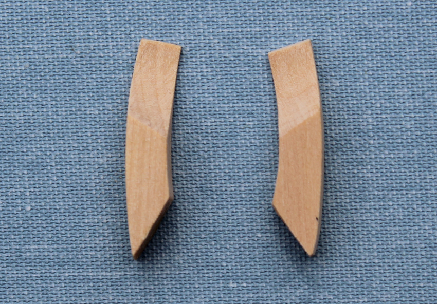
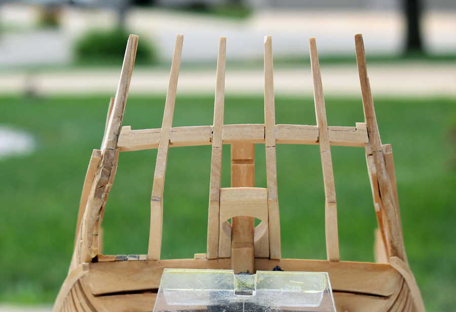
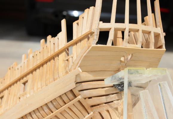
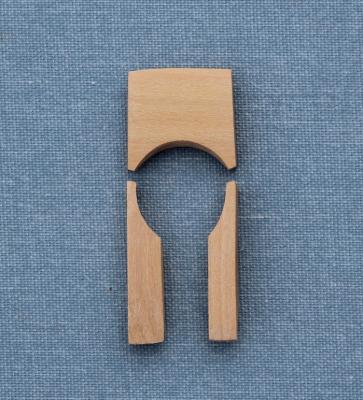
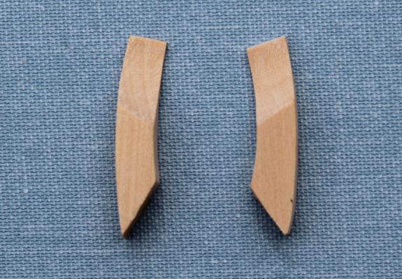
Next on the agenda is the helm port. I worked on this while the stern was being rebuilt so the corrections will not be evident until the next posting. The helm port is a opening in the counter to allow the rudder to pass into the ship. It needs to be large enough to accommodate the rotation of the rudder. It is comprised of three pieces, two side pieces and a chock and in construction is very similar to the bowsprit chock. (Loosely translated as a right royal pain in the stern.) At first glance you would say "two straight pieces and a chock, what's so hard about that?" The straight edges' lateral pieces are cut an an angle to match the taper of the sternpost and the cant of the inner counter timbers. Once that is set, the chock was started. The chock not only has the same side angles as the lateral pieces, but must also lock into their top edge. After I was happy with the fit, I traced the curvature of the inner counter timbers onto the over-sized pieces and sanded in the top and bottom curvature off the model with a Dremel. The opening in the helm port is perpendicular to the water line. The aft end of the chock was left rough at this point and will be finished when the knuckles of the counter are shaped.

-
Druxey, I think we are all at least a little OCD if we participate in this hobby. I went back and remeasured everything again. It appears the last time I corrected the elevation the pieces shifted when I clamped them. So I unglued everything, remade the aft starboard deck clamps and rebuilt it yesterday. To prevent the same problem from happening again I glued the quarter deck transom in place and then added the deck clamp after the transom was secured. No pictures yet, but I am much happier with the results. I appreciate you and everyone who alerts me to problems. As you know, when one looks at something for a long time you stop seeing the problems until they are pointed out.