HOLIDAY DONATION DRIVE - SUPPORT MSW - DO YOUR PART TO KEEP THIS GREAT FORUM GOING!
×


Hubac's Historian
-
Posts
3,292 -
Joined
-
Last visited
Content Type
Profiles
Forums
Gallery
Events
Everything posted by Hubac's Historian
-
 Honestly, Bill, that is such a minuscule detail that it does not draw the eye, in the big picture of the model. I don’t see, really, how you could have avoided the issue, as the holes had to be filled. Just remember that the actual ships were always a patch-work of revision and repair 😉
 -
La Licorne in 1:36 Apart from the wale sheer being far too flat, I don’t see much to disagree with, here.
- 386 replies
-
- 2
-

-
- soleil royal
- Heller
- (and 1 more)
-
Agreed that that’s a much better shape to the lower half of the bulkhead.
- 386 replies
-
- 1
-
-
- soleil royal
- Heller
- (and 1 more)
-
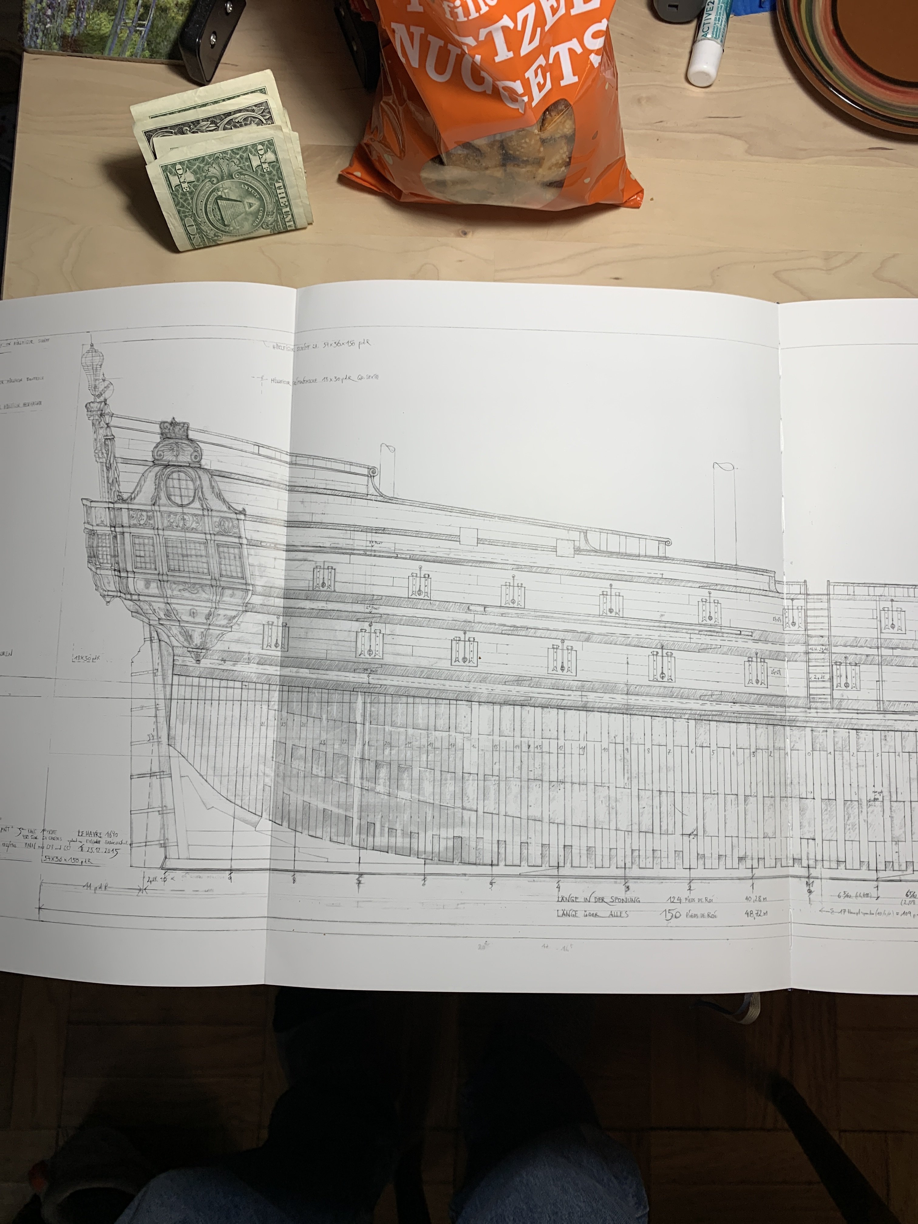
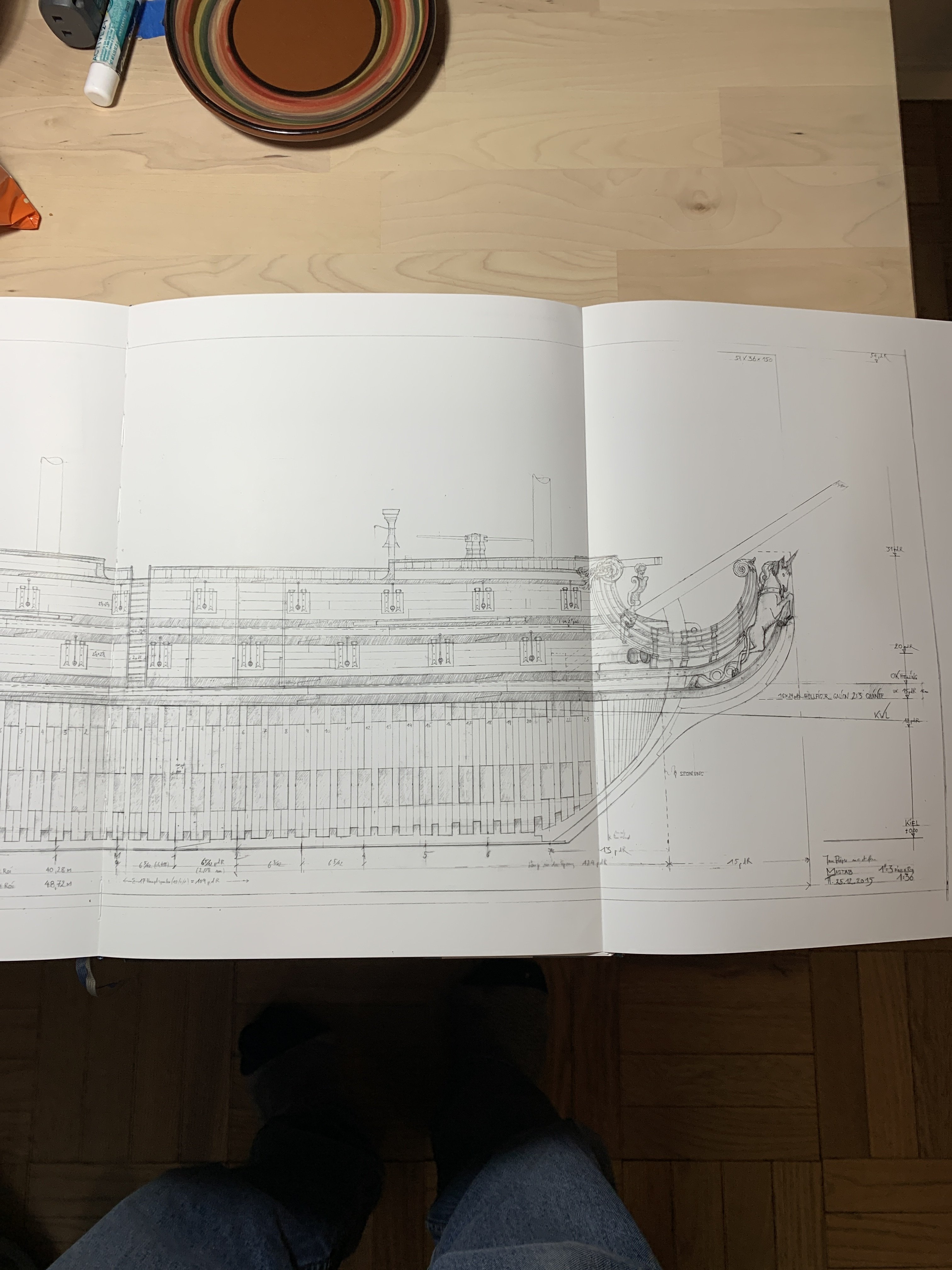
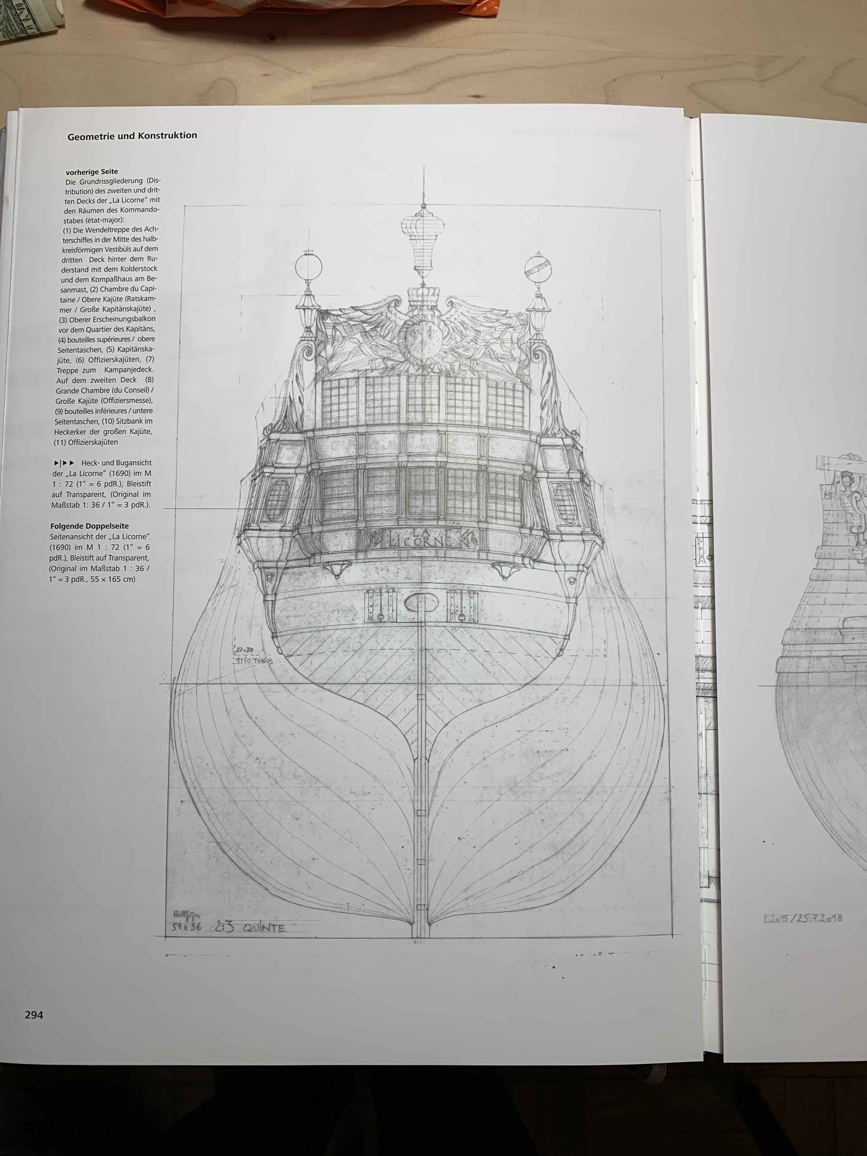
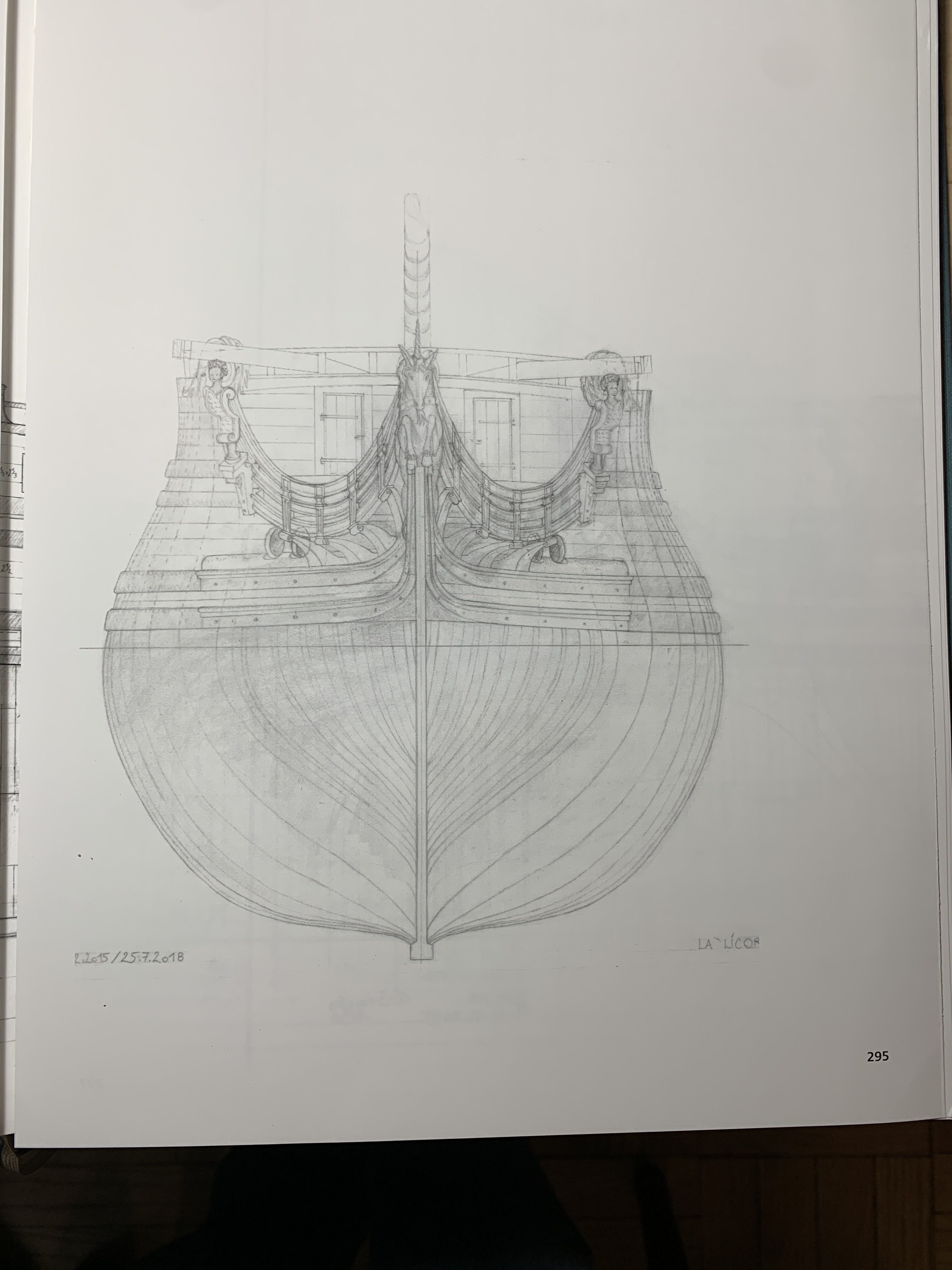
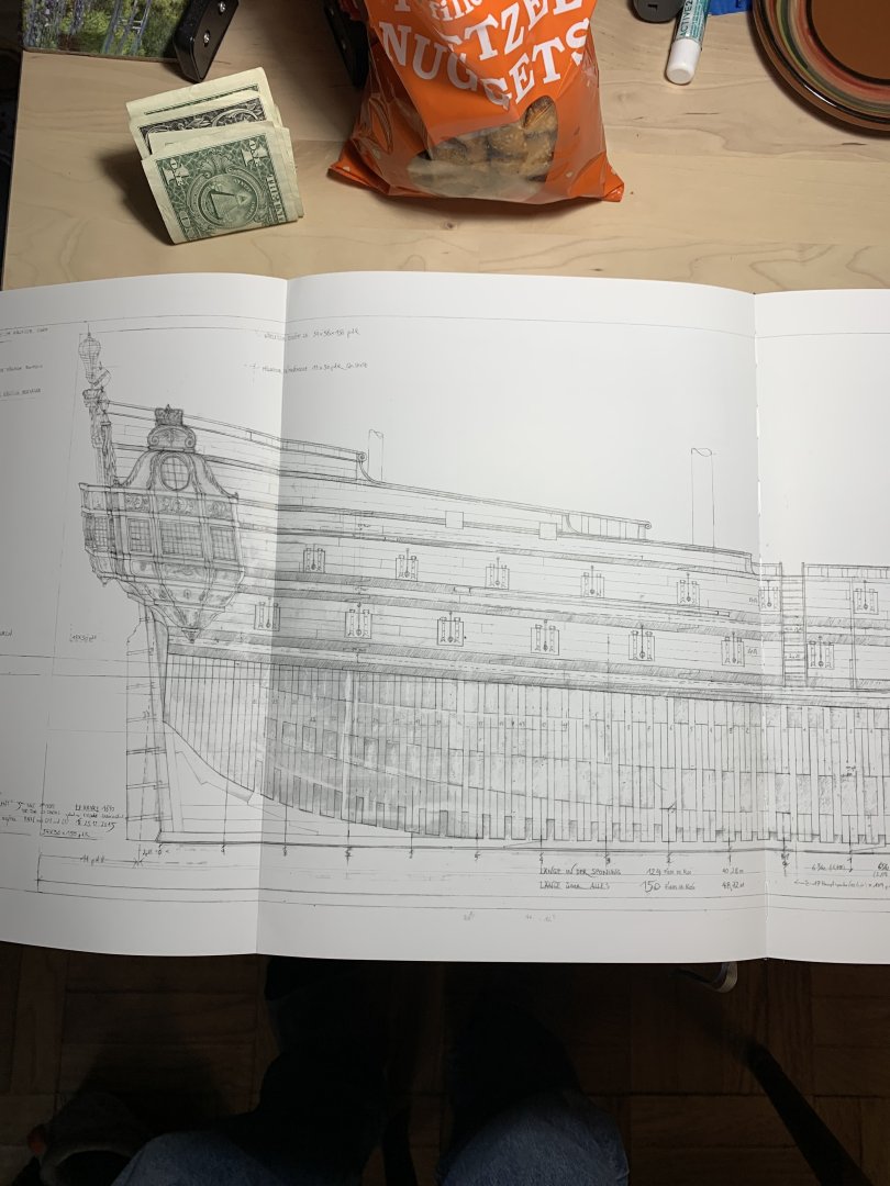
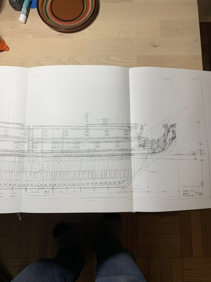
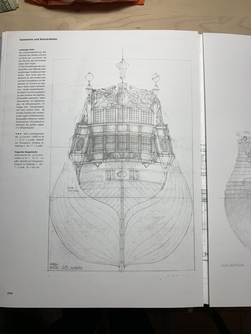
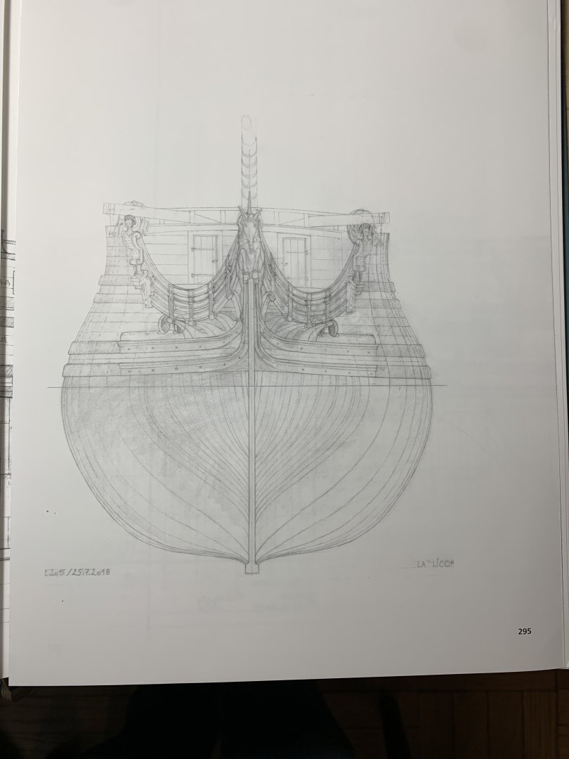
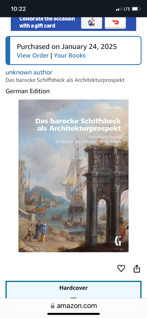
So, on Beckmann’s Tre Kronor log, I encountered the following title: I decided to make an INVESTMENT in the hope that a clearer image of my “Gilded Ghost” portrait might show up in these pages. I was not so naive to think this was likely, though, and bought the book primarily on Beckmann’s recommendation of it. Unlike most books that focus on the 17th Century French navy - it’s organization, material resources and administration - this book focuses on the ships, themselves. More specifically, it focuses on the ornamental programs of specific ships and draws parallels between the architecture of the ships and their land-based counterparts. This is really an in-depth continuation of Pieper’s Floating Baroque. So, despite my mild disappointment at not finding my elusive ship portraits, the book has proved to be well-worth the price of admission! There are so many stern/quarter/bow portraits, all reproduced in crystal-clarity. Pieper’s insights into the allegorical composition of each vessel’s ornamental program are invaluable - particularly for someone like me who has designs on reconstructing a monumental allegory for Soleil Royal 1670. The whole thing has to hang together in a coherent fashion. The real gem of the book is a plan-set created by Pieper, himself. He grew up a huge fan of the TinTin series, and he has drafted a coherent and highly detailed plan of the fictional La Licorne - a French 3rd rate from the time of Colbert’s first building program - that more rigorously adheres to what is known and understood about vessels from this time period. It is all beautifully drawn, and from these plans, one could produce a highly plausible model of this time period. I may have purchased the last available copy, for the moment, but it is well-worth looking for, if these things interest you. The title only comes in German, however, I had such great success reading Versailles de Mer through Google Translate, that I decided to take the plunge. I was rewarded for my bet, as the book translates with nuance and perfect clarity, using GT’s photo capture function on my phone. Anyway, I thought this would be of general interest to all.
- 386 replies
-
- 3
-
-
- soleil royal
- Heller
- (and 1 more)
-
Dan, you have so perfectly captured the utilitarian ambivalence of this time in the ship’s history. One can still see the bones of the beast, but man did they let the old girl go!
-
Gorgeous work, Siggi!
-
Another good rope-handling tip Wefalck, thank you! And, indeed Bill, those are sage words from my MSW friends. Progress, here, has been slow, and continually disrupted by coaching basketball, the holidays, and being sick all the time. This truly has been the worst cold and flu season I can ever remember. I’m currently getting over my fifth cold, since September, and I am not an “unhealthy” person. Sometime in the not too distant future, I’ll have an update on my main deck guns. I’m presently experimenting with rope coils.
- 2,696 replies
-
- 3
-

-
-
- heller
- soleil royal
- (and 9 more)
-
The Vespucci is a fascinating vessel, with lots of interesting deck houses and details.
-
Yup, perfect! I was re-reading through your log yesterday, just marveling at the three re-starts of this project. I was thinking about how relatively easily you managed to disassemble your teenage efforts, without much damage. That may be, in part, because you didn’t flatten the mating surfaces of the keel and stem. Lucky for your re-build, but less good for your current project. I always sand these surfaces flat so that I get a good mating, welded bond. The coarsened surface from the paper grit melts readily. If you double-stick some 150 grit to a hard, flat block (I use my steel ruler), with a few glancing swipes you might be surprised at how un-flat these joints really are.
- 386 replies
-
- 1
-
-
- soleil royal
- Heller
- (and 1 more)
-
All of those tools and items in the foreground of your bow shot, make plainly evident the small scale you are dealing with. Amazed, I remain.
- 301 replies
-
- 1
-

-
- Sovereign of the Seas
- Airfix
- (and 1 more)
-
Not to toot my own horn, Eric, but I could not have done it better myself. I see your problem with the beakhead deck, which is two-fold: the cheeks terminate below the deck, and with a shortened stem - the sprit-mast entry into this deck is now a little awkward. Since you are going to construct a new beakhead bulkhead, anyway, my personal approach would be the following: I would cut a rebate for the forward edge of the beakhead deck (between the port and starboard terminations of the cheeks) into the black plastic of the kit pressing. It looks to me as though you can do this without also cutting into the white styrene of your replacement wales, so that this “cheat” will effectively remain hidden. You’ll have to create new glue ledges for the after-portion of the beakhead deck, but that is an easy enough matter with some styrene strip.
- 386 replies
-
- 1
-
-
- soleil royal
- Heller
- (and 1 more)
-
For fairing, in this instance, sandpaper around a dowel is your best friend, IMO.
- 386 replies
-
- 1
-
-
- soleil royal
- Heller
- (and 1 more)
-
It has been a while since I checked-in, but WOW - Mark, you never disappoint with the fairness of your lines, nor the cleanliness of your craft! It is so gratifying to see her take shape, and I agree that those ship-lapped transom planks are a visual delight. All I can say is BRAVO, and keep on keeping-on!
-
Here is another bow perspective from one of the better and more proportionally drawn plates of Le Album de Colbert: As this drawing dates to the early 1670’s, it is interesting to me that the transverse headrail supporting timbers are drawn as concave. This is in direct opposition to all of the 1672 VdV drawings that show them in the more Dutchy convex form. I’m not really sure what to make of that, but I, personally, would side with the VdV’s, whose drawings were as close to a photographic record as possible for the times.

- 386 replies
-
- 3
-
-
- soleil royal
- Heller
- (and 1 more)
-
All looks great, Eric. As for tracing that curved line in the bulwark extensions, I would simply fair my headrail template to exactly where I want it to be, and then just hold that template close to the extension and trace a clean line. What I like to do with these thin cardboard templates is saturate the cut edges with thin CA. Once that dries, you can wrap a piece of 150 grit paper around a dowel and sand the stiffened edges until they are perfectly fair. The human eye is remarkably sensitive to small bumps, dips and flats. It is well-worth the small investment in time to perfect your patterns.
-
Hi Aleksandr, I am perfectly okay. For a variety of reasons, it was a challenging end to 2024, but most of those issues have been resolved. I’m just hoping for a less hectic 2025. Thank you for your concern. All the best, Marc
- 2,696 replies
-
- 7
-
-
- heller
- soleil royal
- (and 9 more)
-
Your rigging work, Bill, has taken quantum leaps of improvement. All very neat and orderly. Looks fantastic! HAPPY NEW YEAR to you and your family!
-
I’m sorry to hear about the shoulder, Frank, but I’m excited to see you build the Confederacy! I’ll keep an eye peeled for your build log.
- 301 replies
-
- 1
-
-
- Sovereign of the Seas
- Airfix
- (and 1 more)
-
I think it all looks amazing!
-
Your instinct is right, though, IMO. Pulling works better than pushing, in order to control direction of cut.