


Hubac's Historian
-
Posts
3,308 -
Joined
-
Last visited
Content Type
Profiles
Forums
Gallery
Events
Everything posted by Hubac's Historian
-
 Yup, perfect! I was re-reading through your log yesterday, just marveling at the three re-starts of this project. I was thinking about how relatively easily you managed to disassemble your teenage efforts, without much damage. That may be, in part, because you didn’t flatten the mating surfaces of the keel and stem. Lucky for your re-build, but less good for your current project. I always sand these surfaces flat so that I get a good mating, welded bond. The coarsened surface from the paper grit melts readily. If you double-stick some 150 grit to a hard, flat block (I use my steel ruler), with a few glancing swipes you might be surprised at how un-flat these joints really are.
- 422 replies
-
- 1
-

-
- soleil royal
- Heller
- (and 1 more)
-
All of those tools and items in the foreground of your bow shot, make plainly evident the small scale you are dealing with. Amazed, I remain.
- 324 replies
-
- 1
-

-
- Sovereign of the Seas
- Airfix
- (and 1 more)
-
Not to toot my own horn, Eric, but I could not have done it better myself. I see your problem with the beakhead deck, which is two-fold: the cheeks terminate below the deck, and with a shortened stem - the sprit-mast entry into this deck is now a little awkward. Since you are going to construct a new beakhead bulkhead, anyway, my personal approach would be the following: I would cut a rebate for the forward edge of the beakhead deck (between the port and starboard terminations of the cheeks) into the black plastic of the kit pressing. It looks to me as though you can do this without also cutting into the white styrene of your replacement wales, so that this “cheat” will effectively remain hidden. You’ll have to create new glue ledges for the after-portion of the beakhead deck, but that is an easy enough matter with some styrene strip.
- 422 replies
-
- 1
-
-
- soleil royal
- Heller
- (and 1 more)
-
For fairing, in this instance, sandpaper around a dowel is your best friend, IMO.
- 422 replies
-
- 1
-
-
- soleil royal
- Heller
- (and 1 more)
-
It has been a while since I checked-in, but WOW - Mark, you never disappoint with the fairness of your lines, nor the cleanliness of your craft! It is so gratifying to see her take shape, and I agree that those ship-lapped transom planks are a visual delight. All I can say is BRAVO, and keep on keeping-on!
-
Here is another bow perspective from one of the better and more proportionally drawn plates of Le Album de Colbert: As this drawing dates to the early 1670’s, it is interesting to me that the transverse headrail supporting timbers are drawn as concave. This is in direct opposition to all of the 1672 VdV drawings that show them in the more Dutchy convex form. I’m not really sure what to make of that, but I, personally, would side with the VdV’s, whose drawings were as close to a photographic record as possible for the times.

- 422 replies
-
- 3
-
-
- soleil royal
- Heller
- (and 1 more)
-
All looks great, Eric. As for tracing that curved line in the bulwark extensions, I would simply fair my headrail template to exactly where I want it to be, and then just hold that template close to the extension and trace a clean line. What I like to do with these thin cardboard templates is saturate the cut edges with thin CA. Once that dries, you can wrap a piece of 150 grit paper around a dowel and sand the stiffened edges until they are perfectly fair. The human eye is remarkably sensitive to small bumps, dips and flats. It is well-worth the small investment in time to perfect your patterns.
-
Hi Aleksandr, I am perfectly okay. For a variety of reasons, it was a challenging end to 2024, but most of those issues have been resolved. I’m just hoping for a less hectic 2025. Thank you for your concern. All the best, Marc
- 2,699 replies
-
- 7
-
-
- heller
- soleil royal
- (and 9 more)
-
Your rigging work, Bill, has taken quantum leaps of improvement. All very neat and orderly. Looks fantastic! HAPPY NEW YEAR to you and your family!
-
I’m sorry to hear about the shoulder, Frank, but I’m excited to see you build the Confederacy! I’ll keep an eye peeled for your build log.
- 324 replies
-
- 1
-
-
- Sovereign of the Seas
- Airfix
- (and 1 more)
-
I think it all looks amazing!
-
Your instinct is right, though, IMO. Pulling works better than pushing, in order to control direction of cut.
-
Okay, I will elaborate more tomorrow, but you really need far less than you might think, and could probably pull this off with a standard EXACTO #11 blade.
-
I like your approach with this figure, Eric. Personally, I would spend some time engraving some “movement,” or striation into her hair. The kit figures are a good guide for this.
- 422 replies
-
- 1
-
-
- soleil royal
- Heller
- (and 1 more)
-
You may have to re-locate the gammoning blocks on the sprit-mast so that they align vertically with the gammoning slots on the cutwater.
- 422 replies
-
- 1
-
-
- soleil royal
- Heller
- (and 1 more)
-
When I’m trying to take accurate inside measurements, as when you are trying to determine what the new bottom and top spans of your beakhead bulkhead need to be, I like to use two lengths of styrene scrap plank that are each shorter than the shortest span. I taper the ends to a blunt “point”. Then I hold the strips between my fingers, one over the other, and slide them outward until my “points” make contact with the hull interior. I have a sharp (wicked sharp!) pencil, at the ready, to mark the overlap line of the styrene strips. I can then transfer that span to a good steel ruler (with up to 1/64” increments) for a reliably accurate measurement.
- 422 replies
-
- 1
-
-
- soleil royal
- Heller
- (and 1 more)
-
Fait accompli!
-
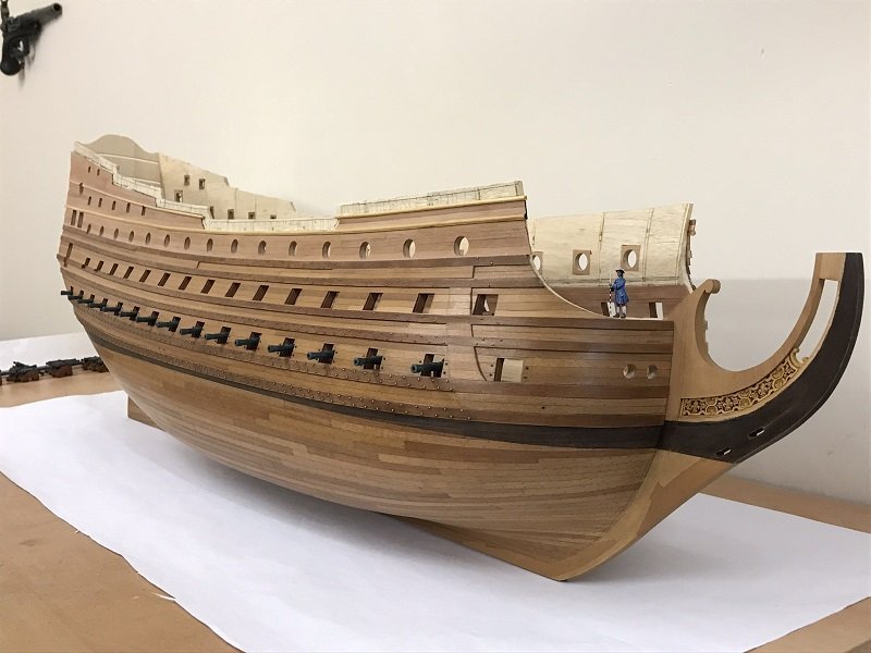
Okay, so the former battens are only temporary. They are merely there to lend shape to the planking continuation. Once that has set, though, the formers are ground away with the Dremel drum sanding attachment. The reason you glue the plank to the formers is to ensure that you get a nice, fair bend around the formers. I realize your card profile pattern is approximate, but keep in-mind that this should be a nice fair curve, like what Marc Yeu did here: The run of your pattern looks a little stiff. Ultimately, this curve mirrors the sweeping curve of the top-most headrail. And, yes, the wales should continue forward into the plank extension. This is easy to patch-in, after the rest has been established. Now, as for the DR and the RL, I mention that more for the sake of visitors to your log who might be inspired to take the kit in another direction. What you have established so far, is the correct wale, plank and top sheer for the epoch. The timber railings are correct and the arrangement of the batteries is far more correct for the time. With this as a basis, one could scratch build the stern, quarters and bow for any of those ships, and you would end up with a pretty solid facsimile of what those ships actually looked like. That the dimensional parameters of the hull don’t exactly match the particular dimensions of those individual ships hardly matters for an impressionistic model.
- 422 replies
-
- 1
-
-
- soleil royal
- Heller
- (and 1 more)
-
At gym with my son, so will respond in detail a little later. You are misunderstanding my intent a little bit.
- 422 replies
-
- 1
-
-
- soleil royal
- Heller
- (and 1 more)
-
The other thought I have is that, at this stage of modification that you have established, one could build SR 1671 (of course), but you could also do representations of the Royal Louis of 1668, or the Dauphin Royal of 1668. You could probably also do the Dauphin Royal of 1680, if you eliminate tue poop royal deck and reduce the overall height of the stern a little.
-
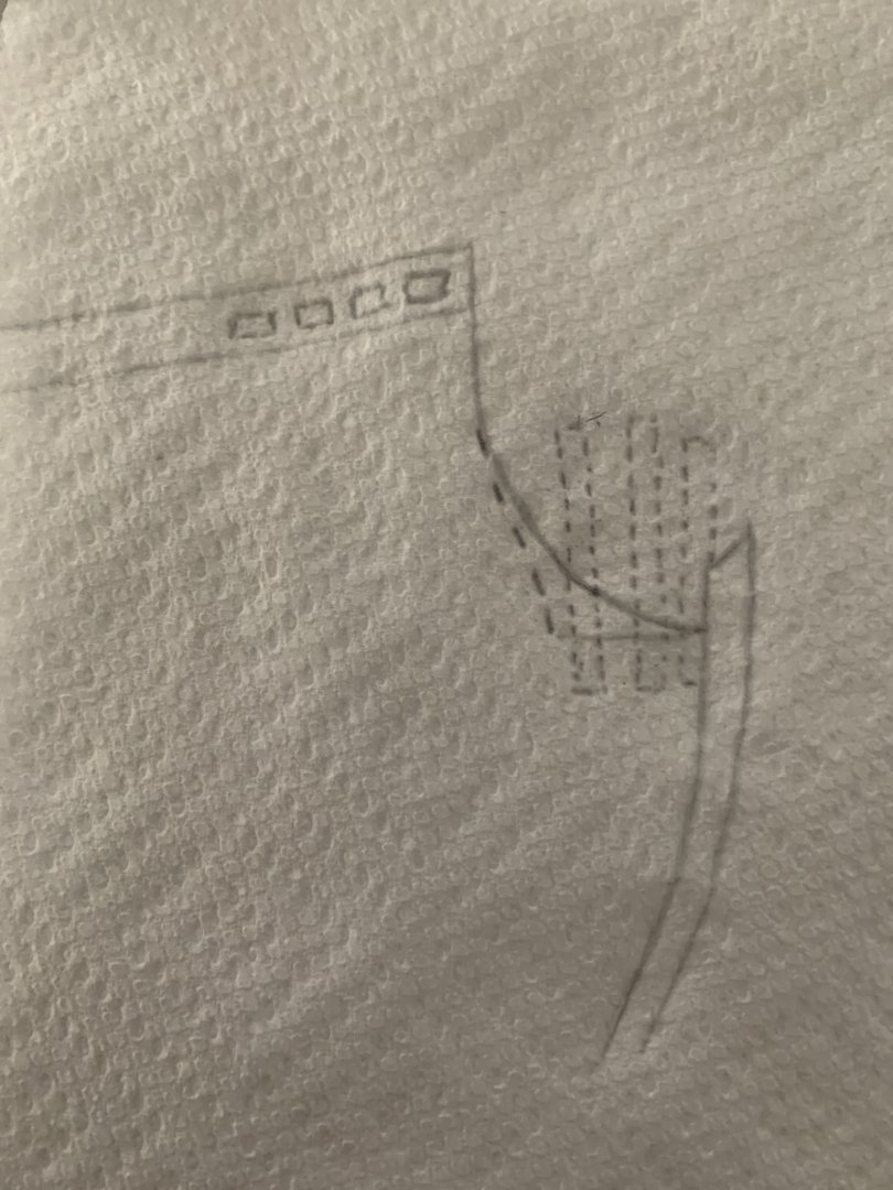
My idea is really pretty simple: I’d begin by sanding the interior surface of the hull smooth, beneath where the short beakhead deck will be. Heller has moulded raised ridges in here that serve no functional or aesthetic purpose. Then, I’d take a few lengths of .100 square styrene rod - at least three, and maybe four - and I’d glue them to this now-smooth surface with styrene cement. These are your formers. Let that set-up strong. Now, you can plank around these in two layers of .032 styrene strip. you’ll want to make sure that their is a really good mating connection between the first styrene strip and the upper main wale; bevel the bottom strip edge, accordingly. Be sure to use two different widths of strip so that the seams overlap each other. Also be sure to edge glue the strips to each other. You can induce a curve to styrene strip simply by pulling it between the spine of a knife and a hard surface. Repeated passes introduces incrementally more curve. This will reduce or eliminate the need for clamping beyond finger pressure for 20-30 seconds, until the bond sets. IMPORTANT: you will also be gluing the first-layer planks to the formers. Once all of that is set, you can establish the descending arc of the new planking, and trace that profile onto the outsides. I like to use a 1/2” coarse sanding drum in my Dremel to blast away waste. The #2 setting will cut without excessive melting, if you just pull away every few seconds. Get close to your line, but give yourself a little room for hand-fairing. Lastly, use that drum sanding attachment to blast away the formers on the back. With a little fore-thought, one can make it so that the second plank layer matches the width of the scribed planking on the hull. I would just sand a micro-bevel onto the plank edges so that those lines show. Or you could simply scribe-in the lines afterwards.
- 422 replies
-
- 1
-
-
- soleil royal
- Heller
- (and 1 more)

