


drobinson02199
-
Posts
1,021 -
Joined
-
Last visited
Content Type
Profiles
Forums
Gallery
Events
Posts posted by drobinson02199
-
-
-
Spyglass:
Great suggestion, which I took -- see picture and much improved rudder appearance.
Re the barrels: I tested each carriage as I mounted it by making sure I could place a cannon through the windows -- particularly important because I framed the windows which makes them smaller. One or two are tight -- but I can get it done.
Regards,
David
- vossy, Martin W and Landlubber Mike
-
 3
3
-
Spyglass -- Thanks for the comments. Some answers to your questions:
1) Yes, I am leaving the top rudder pintle unconnected on purpose. I did it because once it's on the shelf, only the really sharp eyed like you would notice, and getting the other three aligned was difficult -- and they were barely aligned -- so I didn't want to add a fourth one into that equation. There's actually a fifth one provided and showing in the Amati pics, but on my model there's no room for it.
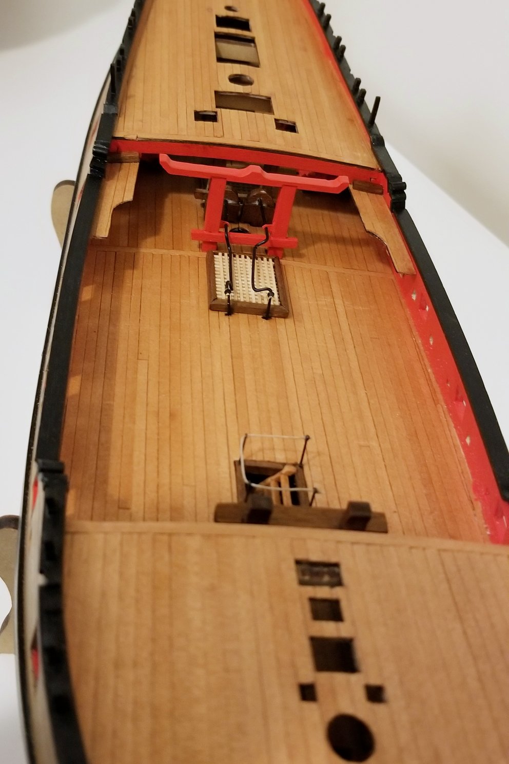
2) The under deck gun carriages are painted and mounted in place, so I just have to insert the guns through the gun ports. I'm waiting to the very last for that so I don't hit one and knock the gun carriage loose.
3) Yes, again your sharp eyes picked up those notches. I acknowledged this in an earlier post, and it's a learning for me. It comes from the plank bender blade biting through on that side. I actually don't need the plank bender, as my steamer will take care of all the bend I need. I didn't notice those notches until after I had mounted the planks and I wasn't going to rip them out. So for finished planks, no more plank bender. It's fine for layer 1, but not layer 2. I didn't get this on the Revenge, so I think it must be some aging in the plank bender and misalignment of the blade.
Regards,
David
-
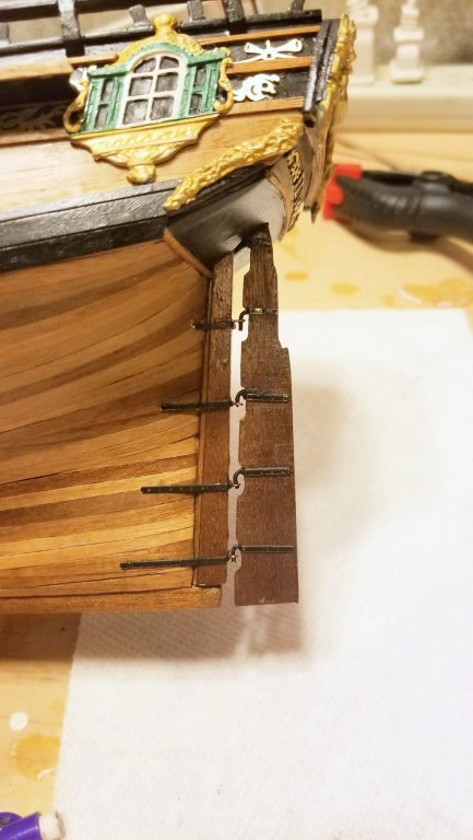
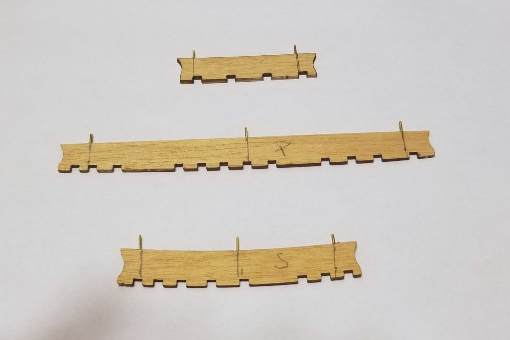
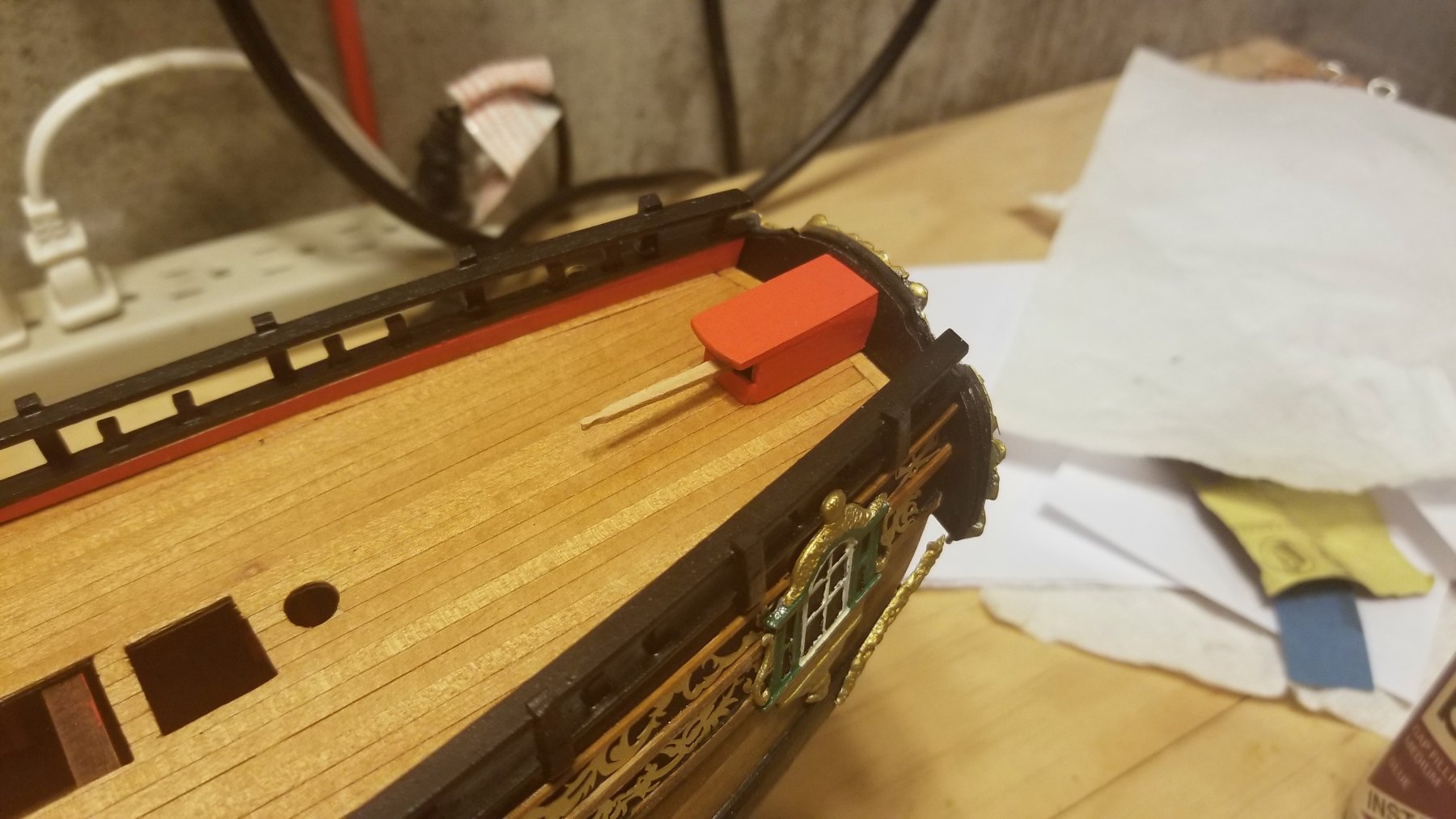
Worked on channels: first picture shows channels with pins in. They are only 1.5mm, so it's delicate drilling.
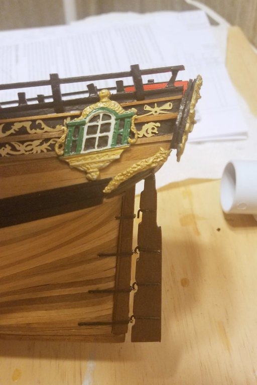
Second pic shows the channels installed on the ship.
Regards,
David
- Martin W, paulsutcliffe, Jim Rogers and 3 others
-
6
-
Rudder mounted as well as tiller & tiller housing.
Regards,
David
- Landlubber Mike, vossy, JpR62 and 2 others
-
5
-
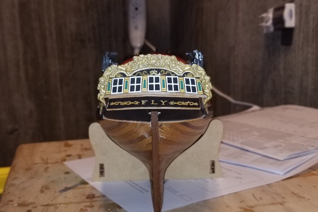
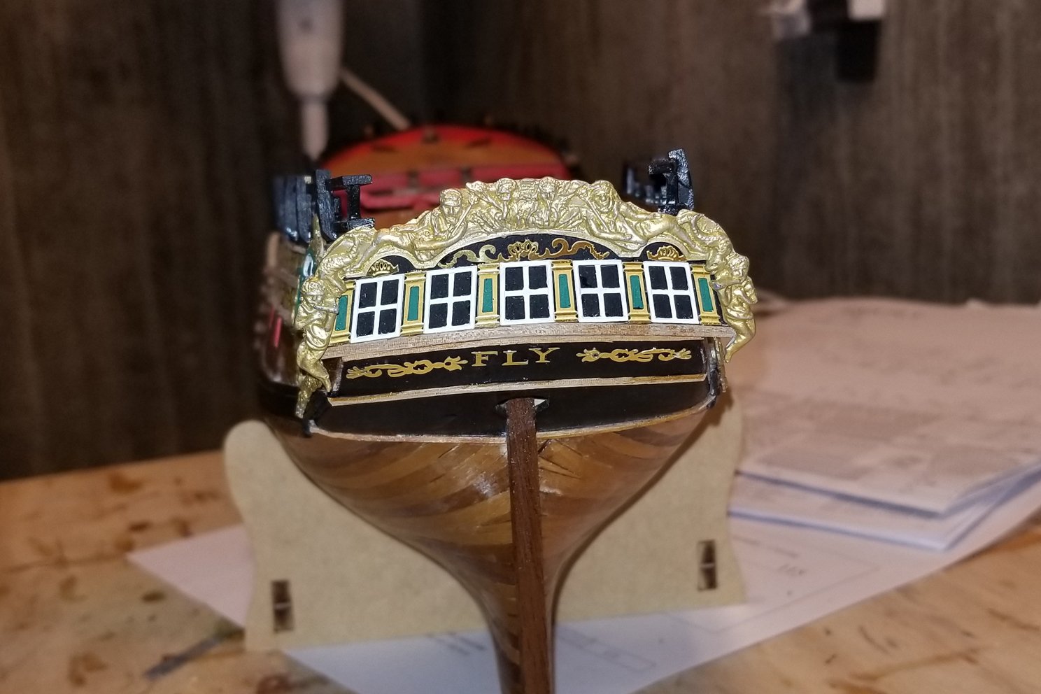
I worked too hard on the stern gallery to have that off-center lettering spoil it, so I removed everything in that section, repainted, and remounted.
This time I aligned the letters on a piece of paper, and then picked them up with a small piece of painting tape. Added glue, applied the set, and then peeled the tape. That did the trick.
Regards,
David
-
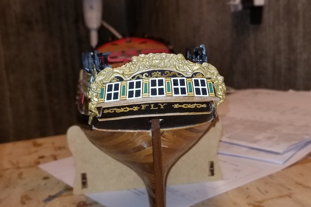
[NOTE: I HAVE REDONE THE STERN PICTURED IN THIS POST. SEE WHY HERE AND THEN REDONE STERN IN NEXT POST]
Finished the stern. "FLY" is not quite centered -- the letters are devilishly small, and the CA gel I use that typically gives me at least 5 sec to slide things into alignment decided to grab right away, so I ended up with the "L" closer to the "F" than I had planned, and that governed spacing to the "Y". Nevertheless, I'm happy with the stern decoration overall, and the green highlights worked well.
Regards,
David
-
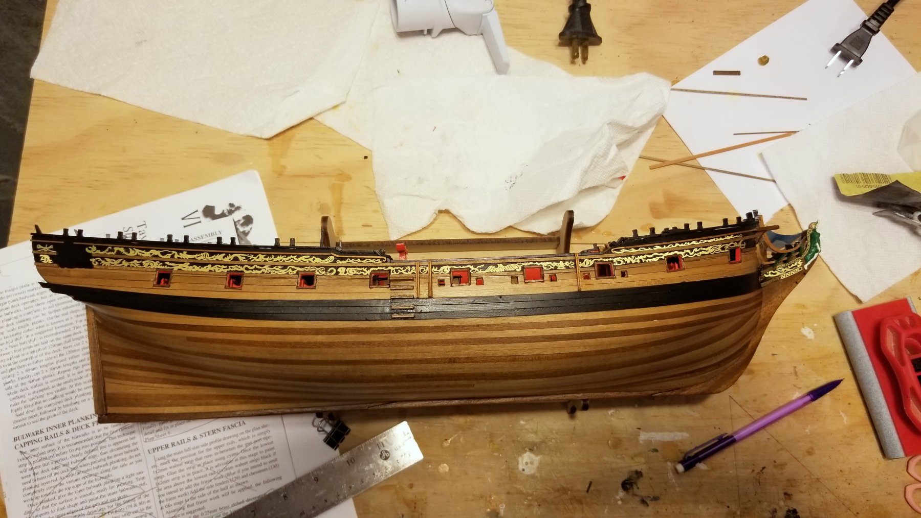
First side now finished, with addition of the stern side window and the top rail. I noticed that the stern side windows in the Amati pics and some other build logs are more simply painted, and having now done these with discrete window frames, I can see why. Lots of retouching multiple times.
Now on to the other side, and then the stern fascia.
Regards,
David
20180504_100328.thumb.jpg.444f35fe45013953f77c7e06636be3b7.jpg)
- Jim Rogers, coxswain, Martin W and 3 others
-
6
-
Decoration on first side completed (except for the large stern windows, which I'm painting now). The approach of using the window cutouts on the decorations worked really well and everything lined up.
I also found that the best way to fit the decoration that abuts the curved endings of the top rail is to dry fit the rail and position it with the decoration dry-fitted, to get both right as it's a tight and exacting fit.
Regards,
David

-
The lowest side rails are now in, and I have painted the hull above them, ready for decoration.
I'm going to do this side all the way through first, so I can do the other side (which will be my display side) better if I learn anything unexpected.
Regards,
David
-
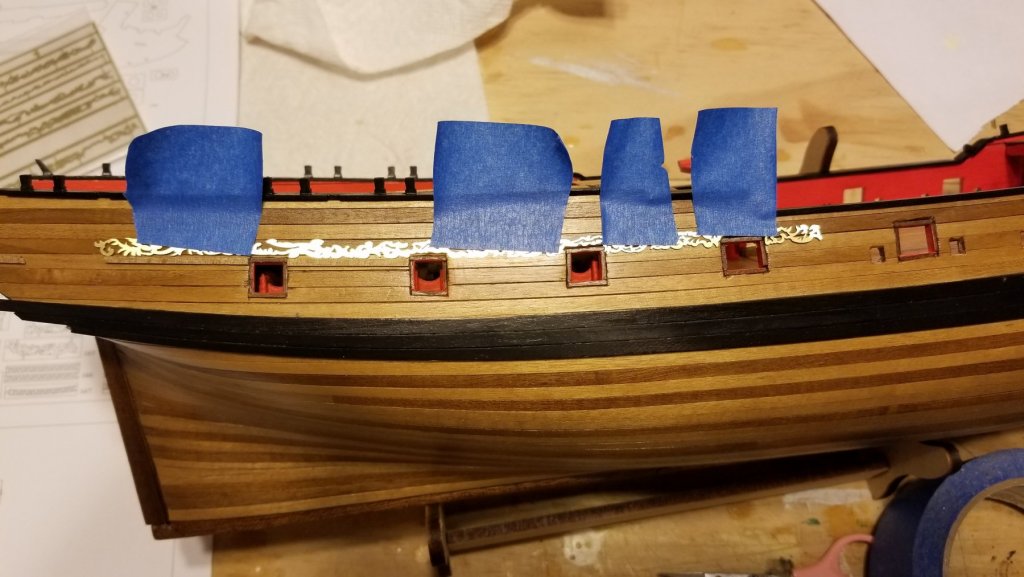
I have started on the side rails. The instructions suggest fixing the lowest rail according to the plan drawings, then attaching the lower row of decorations, then fixing the next rail to the top of those, and so forth.
When I went to the plans and took measurements, I wasn't confident in how they were matching the actual boat, and was concerned that the decorations would not line up properly -- would I miss the window alignment or something further up.
Since the lower row of decorations has cutouts for the tops of the windows, the alignment of the decorations to the windows is really the critical thing. So per the attached picture, I aligned the decorations on the windows and taped them. Now I can install the lower rail up against them, and know that my starting point will work all the way up. Same thing going across the center -- I can align the top of the decoration to a dry-fitted second rail.
Regards,
David
-
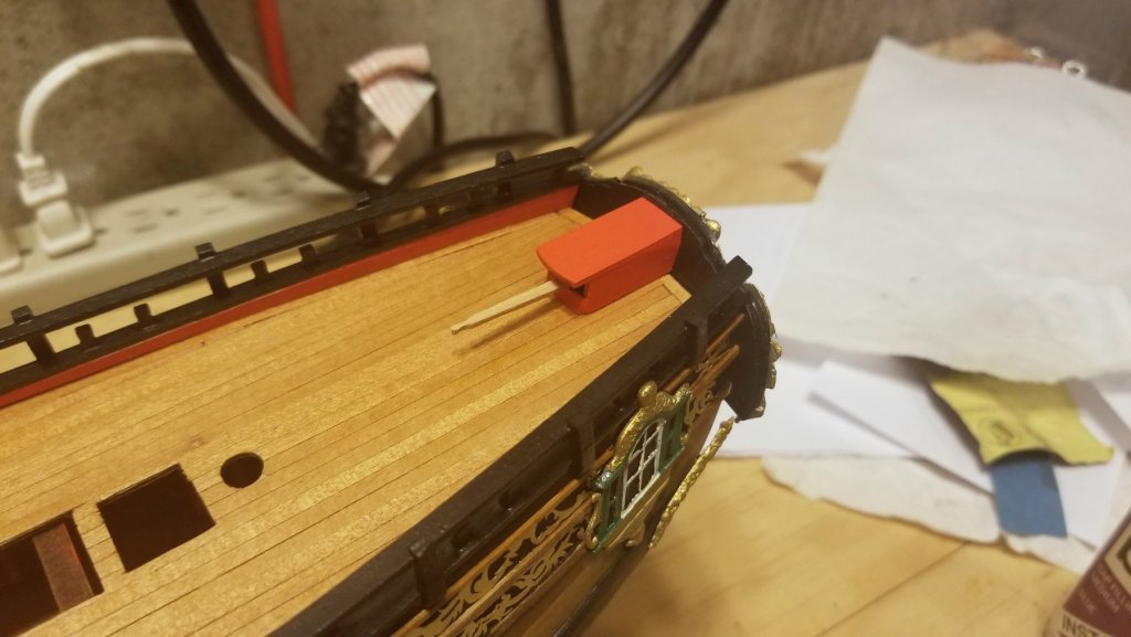
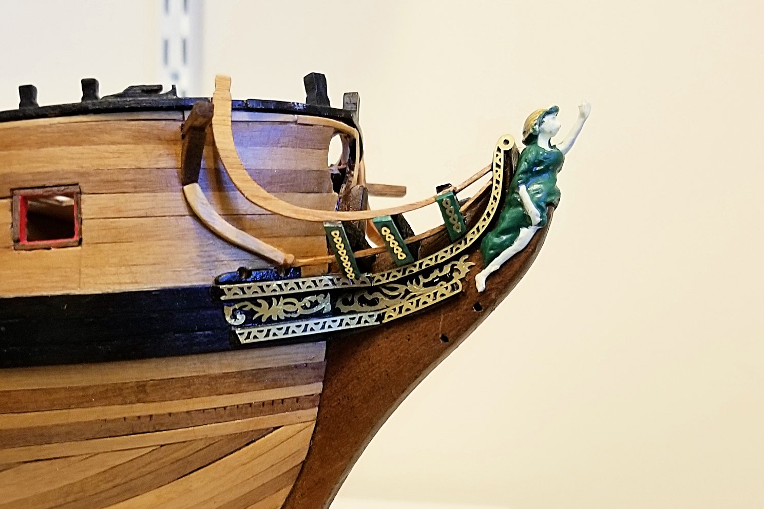
Bow detail completed, and I made plenty of mistakes -- if you are sharp eyed (or even not so sharp eyed) you'll be able to pick them out. Nevertheless, I'm satisfied with the overall look.
Some notes:
- The instructions call for the figurehead's wrap and the small strips to be blue, but I like green better so I used that color.
- The lighter piece leading up to the cathead support is something I had to fabricate. The instructions call for brass strip to be "manipulated" into shape, but I tried it and got nowhere, so I used some leftover wide basswood. In retrospect, I should have cut it from a corner of one of the walnut ply laser sheets -- one of my several mistakes here.
- The instructions say to paint the brass yellow or gold, but I don't get the point. The brass in its natural color looks great.
Figuring out what went where was something of a challenge given the instructions and drawings, but there are enough pics on the internet and in build logs that I was finally able to figure it out.
There is also a pic showing some minor progress on the deck.
Now on to the side rails and decorations. Looking forward to that.
Regards,
David


- vossy, Martin W, Jim Rogers and 4 others
-
7
-
-
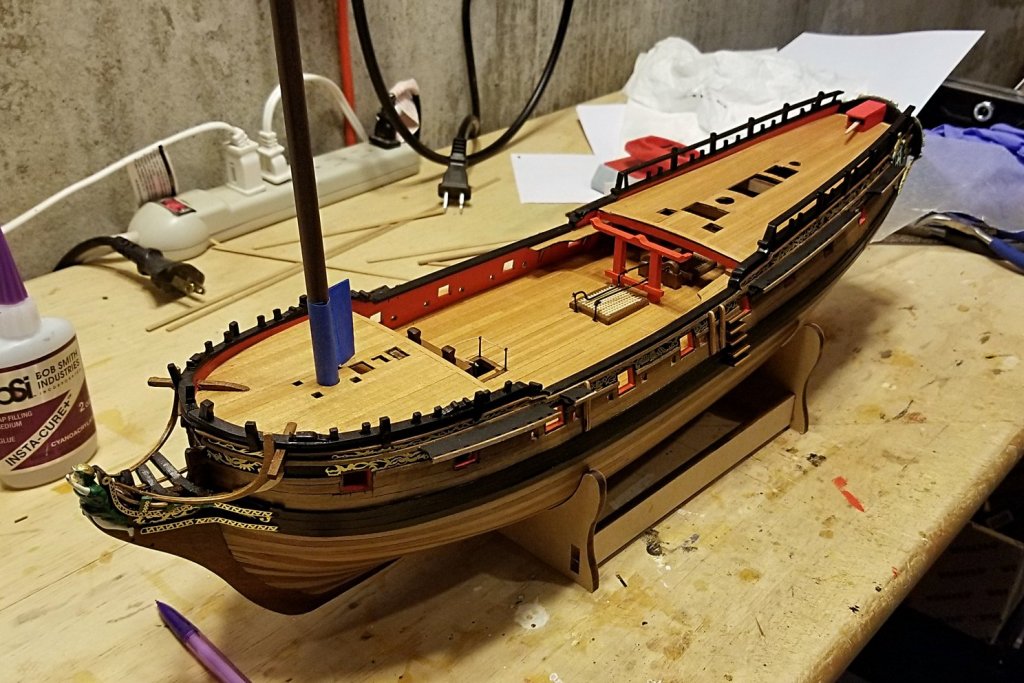
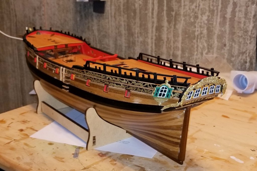
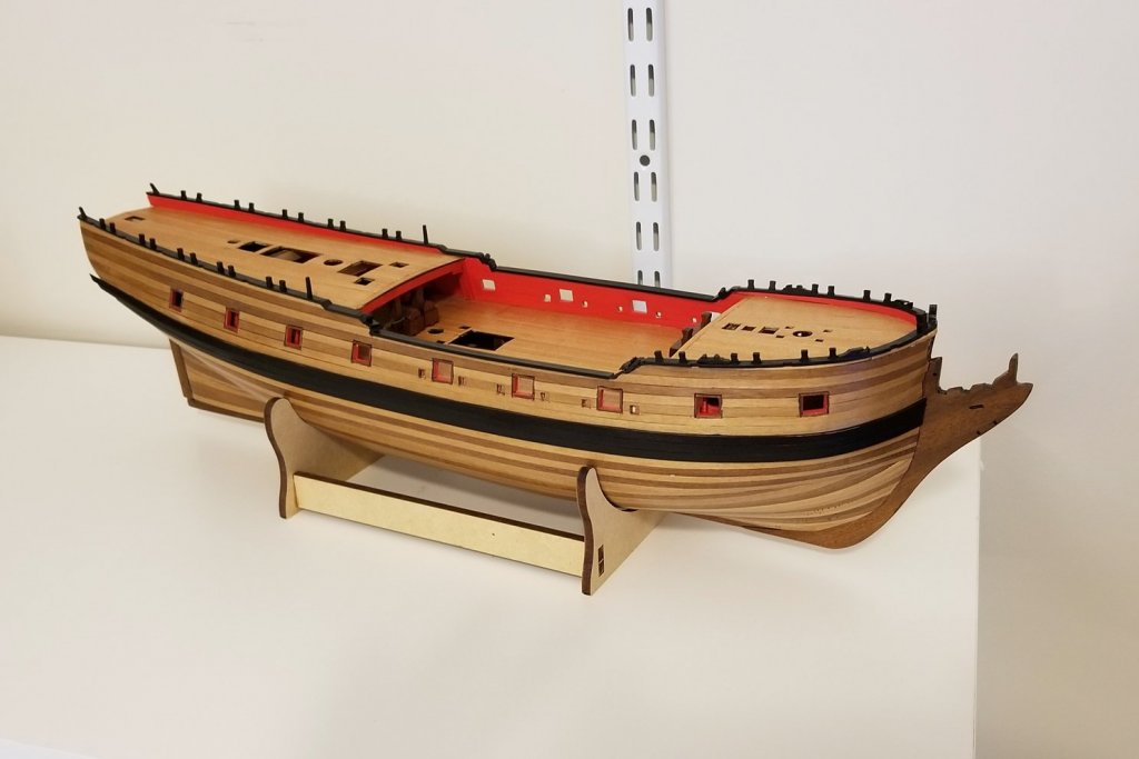
Have now finished the decks, inner bulwarks, and cap rails. I like the color scheme on this model a lot.
Regards,
David
- Martin W, Old Collingwood, coxswain and 5 others
-
8
-
-
Spyglass -- Thanks for the log references. I really love your cannon rigging, but it runs beyond my level of ambition or patience -- particularly the metal drilling, which is always a daunting prospect for me. When I built the Mount Washington, there was metal drilling called for and I couldn't get it to happen, so I bailed out with CA glue (fortunately, I wasn't building a running model).
Regards,
David
-
Chris:
I also really like that parquet planking pattern. Was that in the kit plans, or something you just did?
The doors are also really nice looking. You have a real talent for very clean workmanship.
Regards,
David
- cog and popeye the sailor
-
2
-
Chris:
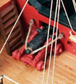
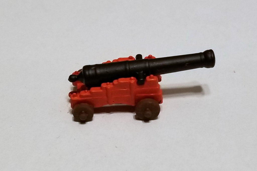
Yes, I painted the carriage the red color with brown wheels. Also had to paint the cannons black.
Here's a snip from the Amati photos of the Fly showing how they have rigged them, which is the way I'm going to do it. If you go in for more elaborate rigging, then you'd build the wood carriages so that eyelets can be installed.
Regards,
David
-
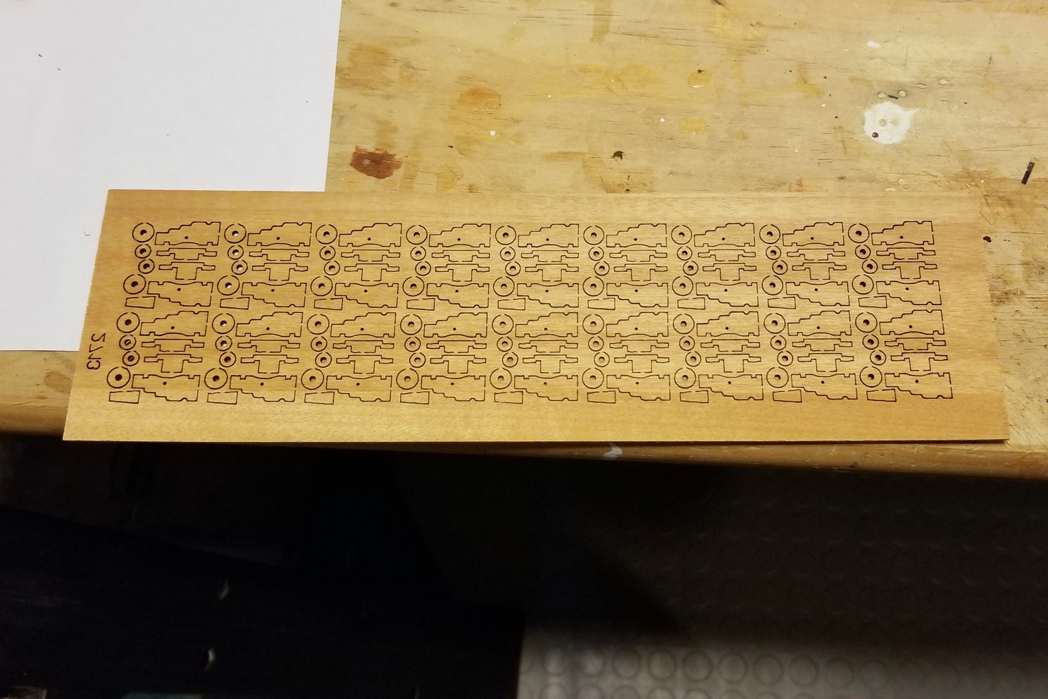
Here's what my cannons will look like. The upgrade kit supplies wood parts for carriages (second picture), but I think the detail on the cast metal carriages is more interesting, so that's what I'm using. I think they call it an upgrade because it permits installation of more complex cannon rigging, which I'm not going to do.
Regards,
David

-
Chris:
She is really looking terrific, and from your pics, it looks like you have yet another deck or structure to add on. She will be impressive!
Regards,
David
- John Allen, cog and popeye the sailor
-
3
-
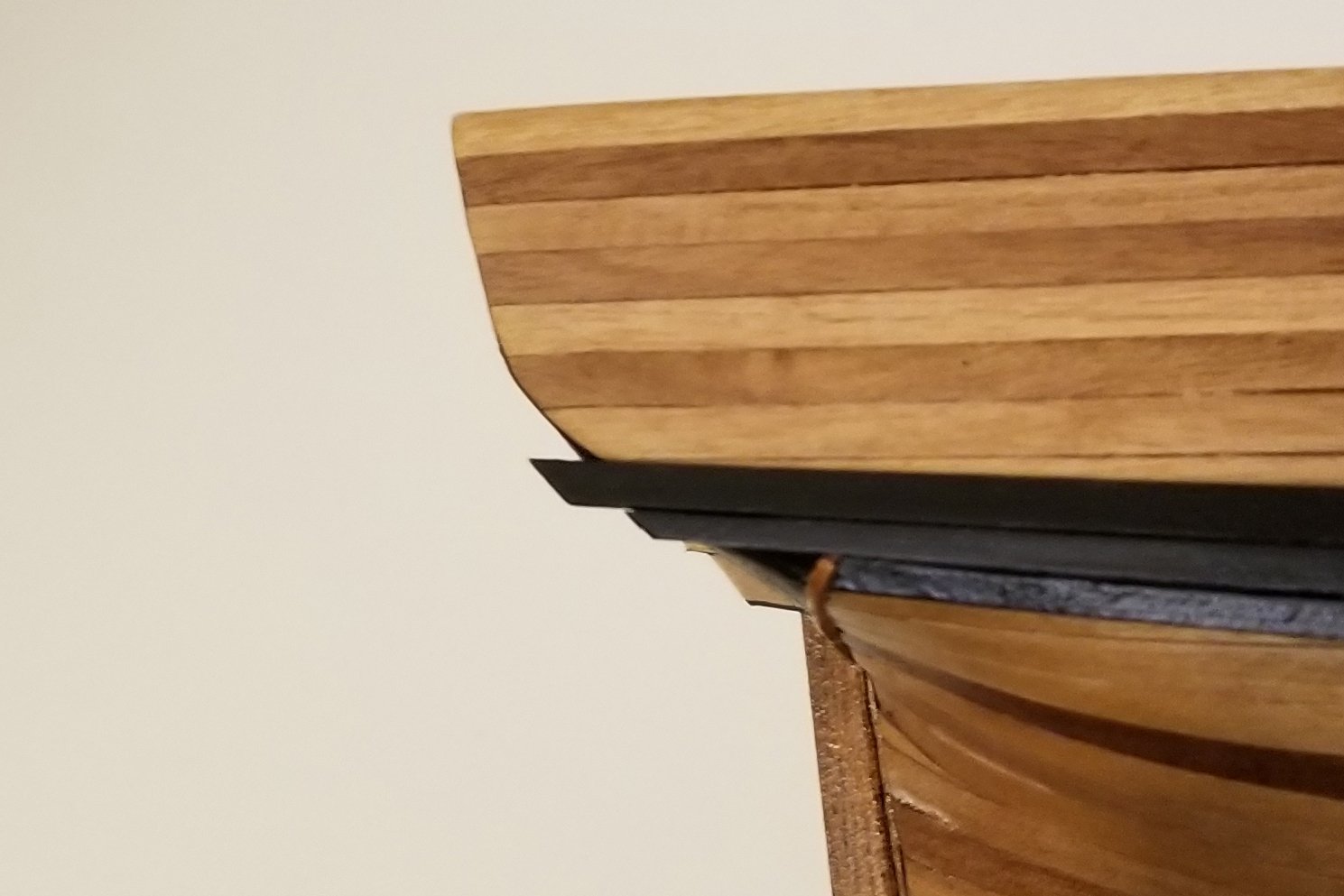
Have now put the main wale on. I pre-shaped and pre-painted each plank before mounting, and then added a second coat of black on the surface after mounting. These pics are after a second coat of varnish. More of that to come.
With the wale on to provide contrast and separation, the multi-color planks look as I had planned for them to.
I studied the drawings and a number of Fly build logs, and Amati's pics, to figure out both the vertical placement of the wale, and how it terminates at the stern. The drawings vary at the stern from all of the build pics I saw, and from Amati's pics. So I took out the stern decoration to see how it will fit, and realized that until I get to doing the stern decoration, I won't really know where exactly to end the top two wale planks, in order to achieve a clean join with the decoration. So as shown in the second picture, I've left those planks slightly extended for later trimming and fixing when I get to that point. I used the vertical placement at the stern that I saw in the pictures, and that best seemed to fit where that decoration will end.
Regards,
David

- Martin W, Landlubber Mike, coxswain and 3 others
-
6
-
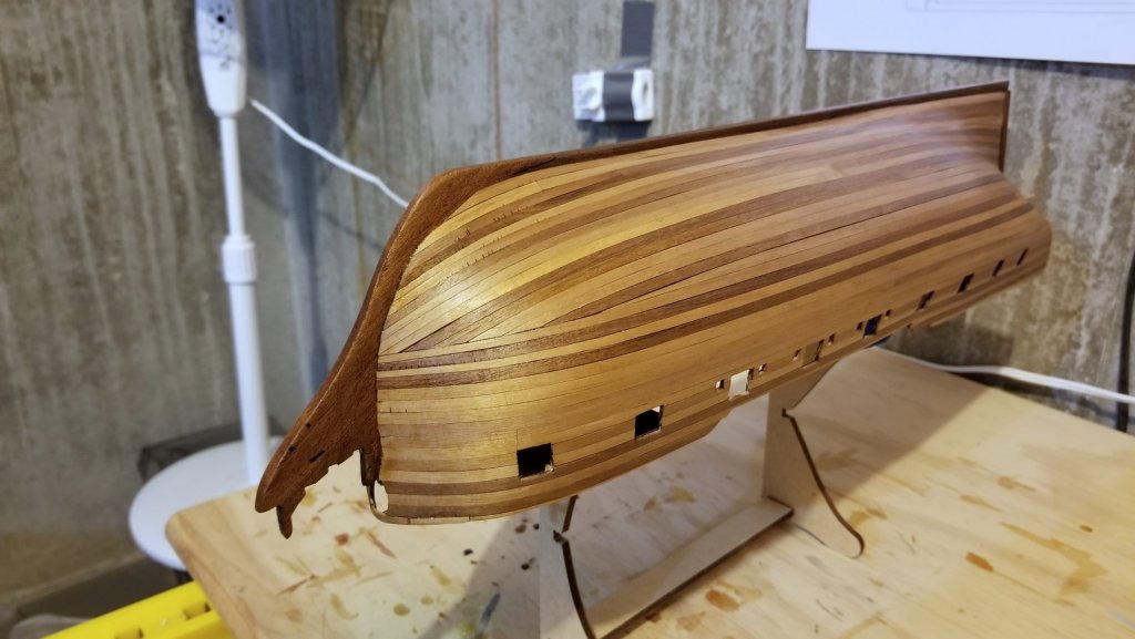
Brian:
I had picked up on the light/dark planking wood from looking at some other Fly build logs, and I actually like the look of the mixed wood on the hull, which I don't intend to paint. So before I started the second layer, I separated the planking walnut into dark and light, and then alternated them in patterns of light/dark/light and light-light/dark-dark/light-light. I left all light wood in the area where the black wale will go so that there is some space between that and any surrounding dark planks.
I can understand how some might not like this look -- but I liked it in earlier logs and thought I'd use it.
Regards,
David
- Landlubber Mike, Martin W and DocBlake
-
3
-
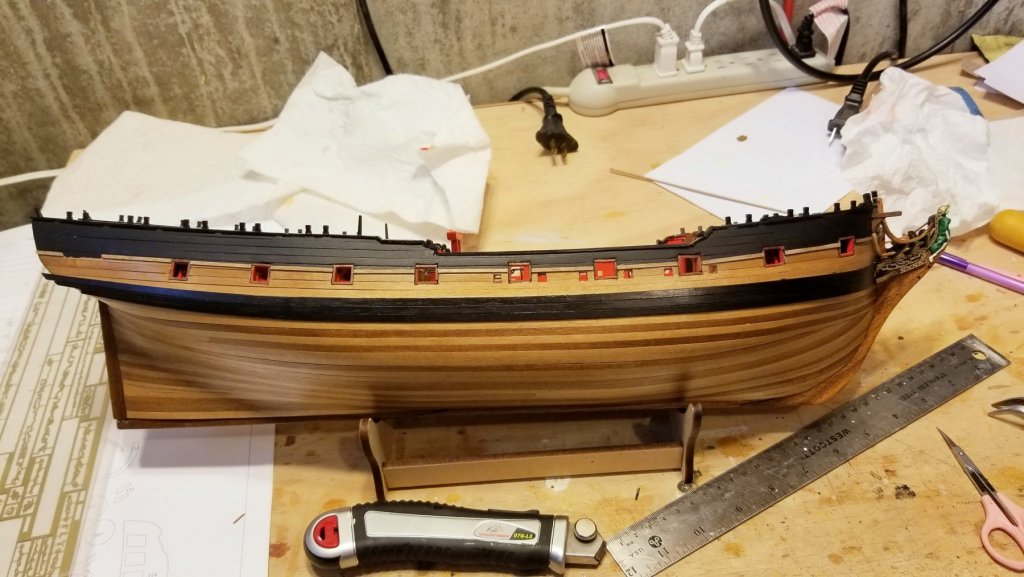
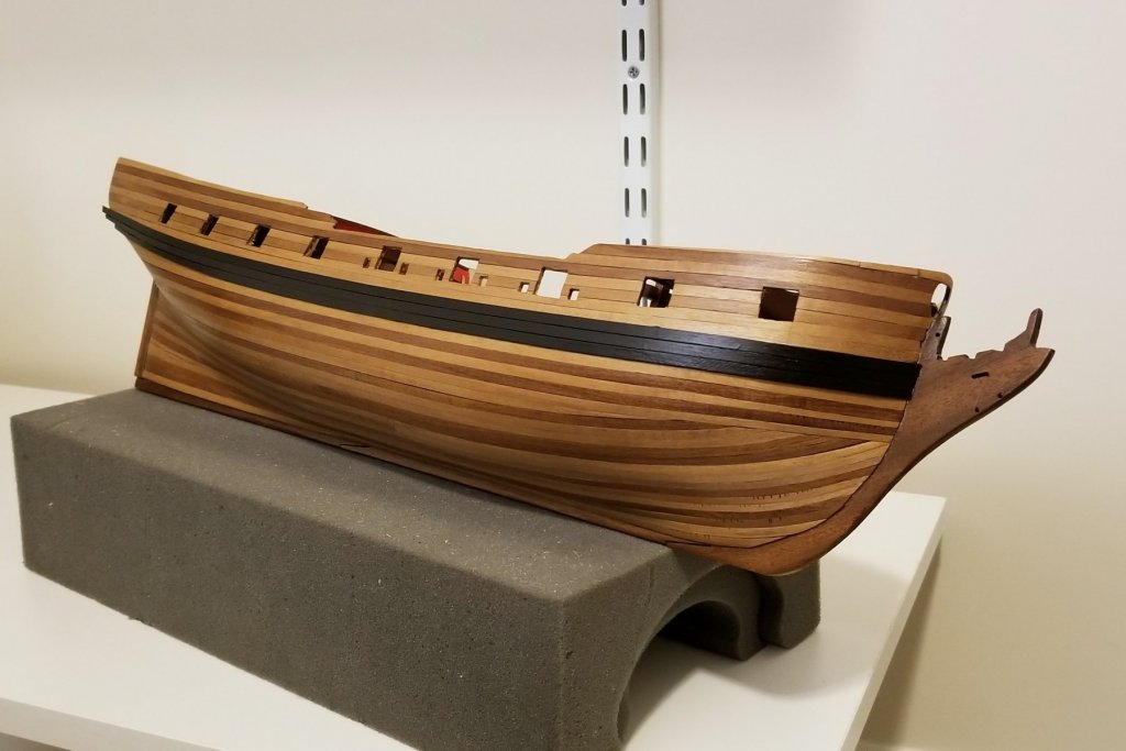
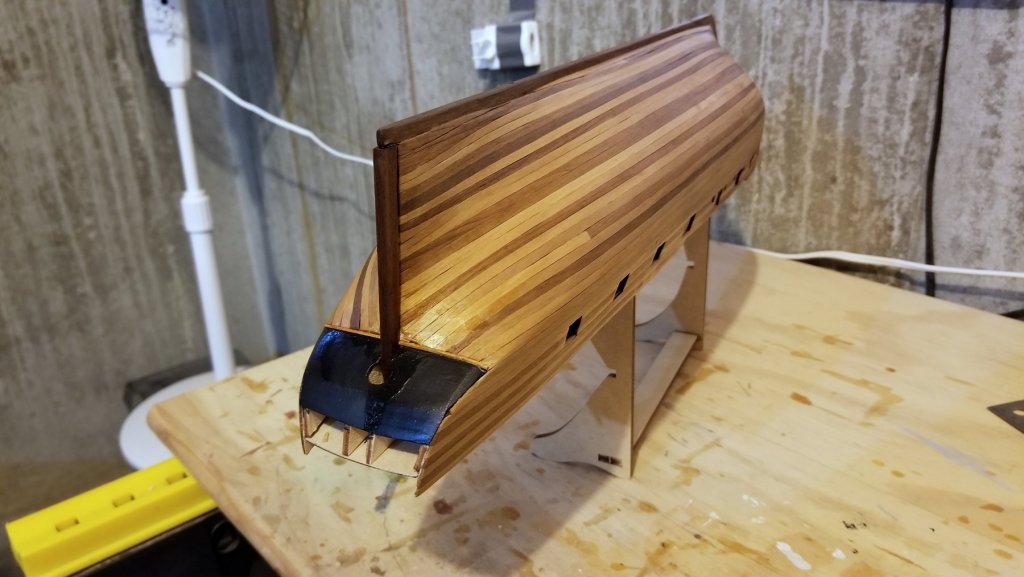
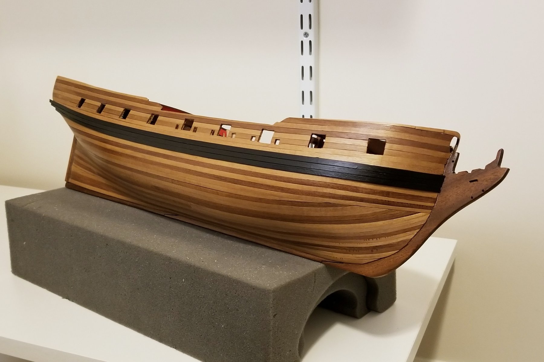
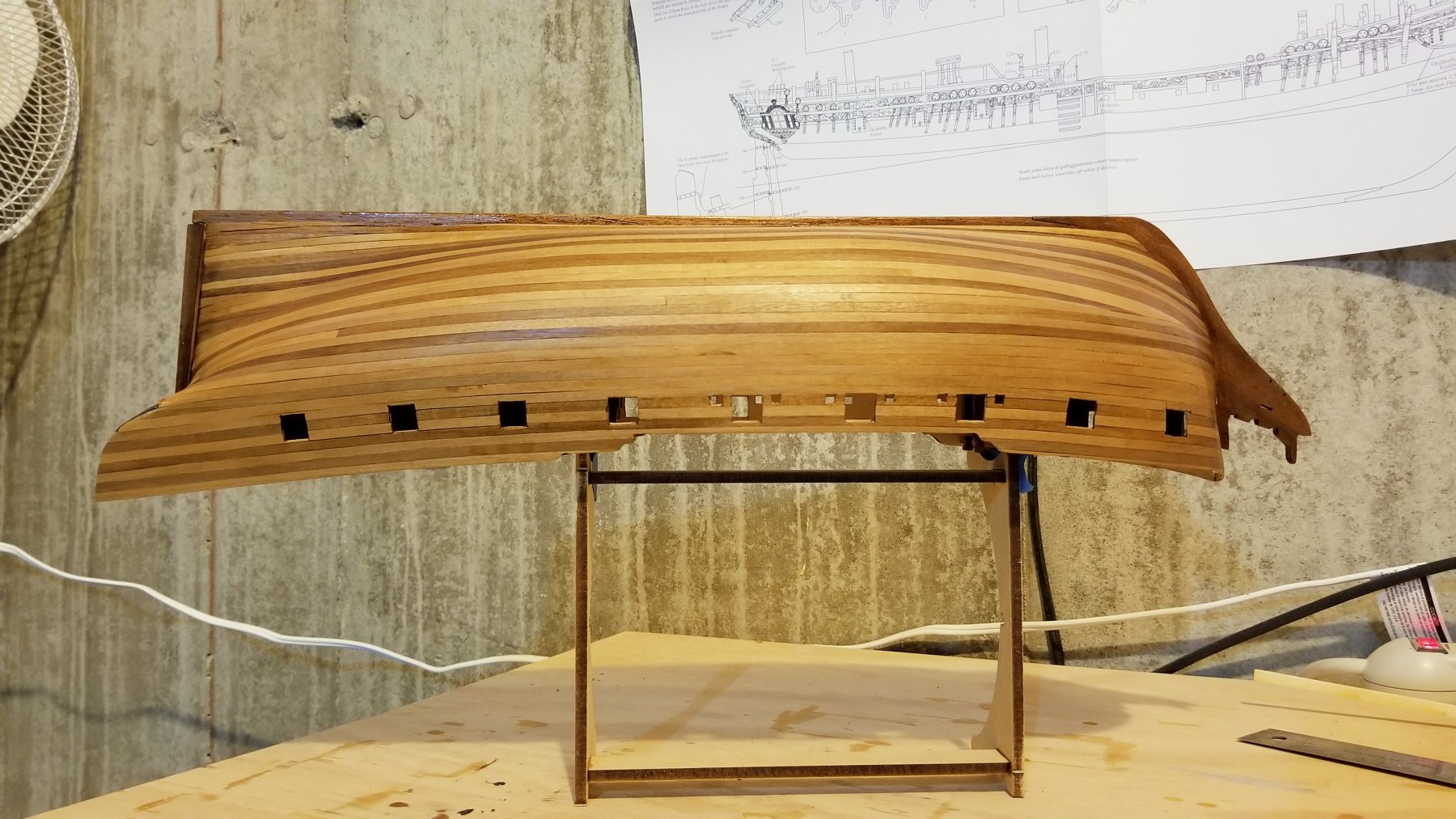
I've finished the second planking and given it a first coat of varnish, which is still drying in the pics below. A few comments:
- There's no way I'm going to paint this hull -- I love natural wood and this wood is particularly beautiful, as I've seen in other Fly build logs.
- The bow view shows how I sorted out the bow planking -- and thanks to a number of you who provided suggestions and comments on this.
- You may see some varnish drip on the stern counter -- I will deal with that in later varnish coats.
One thing that may not show is something I discovered while sanding. I used an Amati plank bender -- the kind that uses a blade to crimp lateral compressions into the back of a plank. What happened in two small areas of the bow is that while sanding, the edges of those compressions came through. The blade must not put an even cut into the back of the plank. It's not a big deal -- could almost pass for coloration in the wood -- and won't be that noticeable. It for sure isn't correctable.
In the future on the second planking, I'll use steam only -- which was very effective and could have been used to accomplish everything I did with the plank bender.
Oh, well -- live and learn.
Regards,
David

- Jim Rogers, riverboat, Martin W and 4 others
-
7
-


20180504_100328.jpg.1cafff17a5d57864eb9cdb9f25965d21.jpg)


Mississippi 1870 by vossy - Sergal - 1:50 - Riverboat
in - Kit build logs for subjects built from 1851 - 1900
Posted
Chris:
This looks great -- I particularly like the stairs and balustrades.
Eagerly awaiting what the fancy railings will look like.
Regards,
David