
Captain Slog
-
Posts
904 -
Joined
Content Type
Profiles
Forums
Gallery
Events
Everything posted by Captain Slog
-
 I just use old CD/DVDs, plenty hard enough to stop the PE deforming and easy on the blade like acrylic. Also cheap and readily available, just throw out when both sides are worn. I use a business card to hold the fret so the freed piece doesn't ping away into the ether. Cheers Slog
 -
Hi Danny, You shouldn't have any issues with it. If I remember correctly it was purely down to my inexperiance; the hull skins are quite large and by No.8 it is a fair size and I was trying to glue too much in one hit. Due to this I started rushing as the glue was starting to off due to the size and I ended up pressing the skin down between the extra balsa wood braces/stringers I put in and it looked absolutely terrible. As you say hindsight is a wondeful thing and knowing what I know now and taking my time it shouldn't have been an issue. I wasn't keen on the overlapping skins at first but to be honest once it was done I didn't mind them, also I couldn't see a suitable solution to butting them at the time. Cheers Slog
-
Hi I bought one of their other sets ( the set with Hitler is always out of stock!) and the figures measure 9mm which comes out at 1800mm or a shade under 6 feet. I tried to paint them with acrylic but couldn't get it to stick. Since they are resin I believe you need to use enamels or at least prime before hand. Cheers Slog
-
For a rookie your work is exceptionally clean, sharp and neat. Look forward to seeing more. Cheers Slog
-
colour of oars
Captain Slog replied to Snow's topic in Discussion for a Ship's Deck Furniture, Guns, boats and other Fittings
I would guess snowy coloured oars would be white -
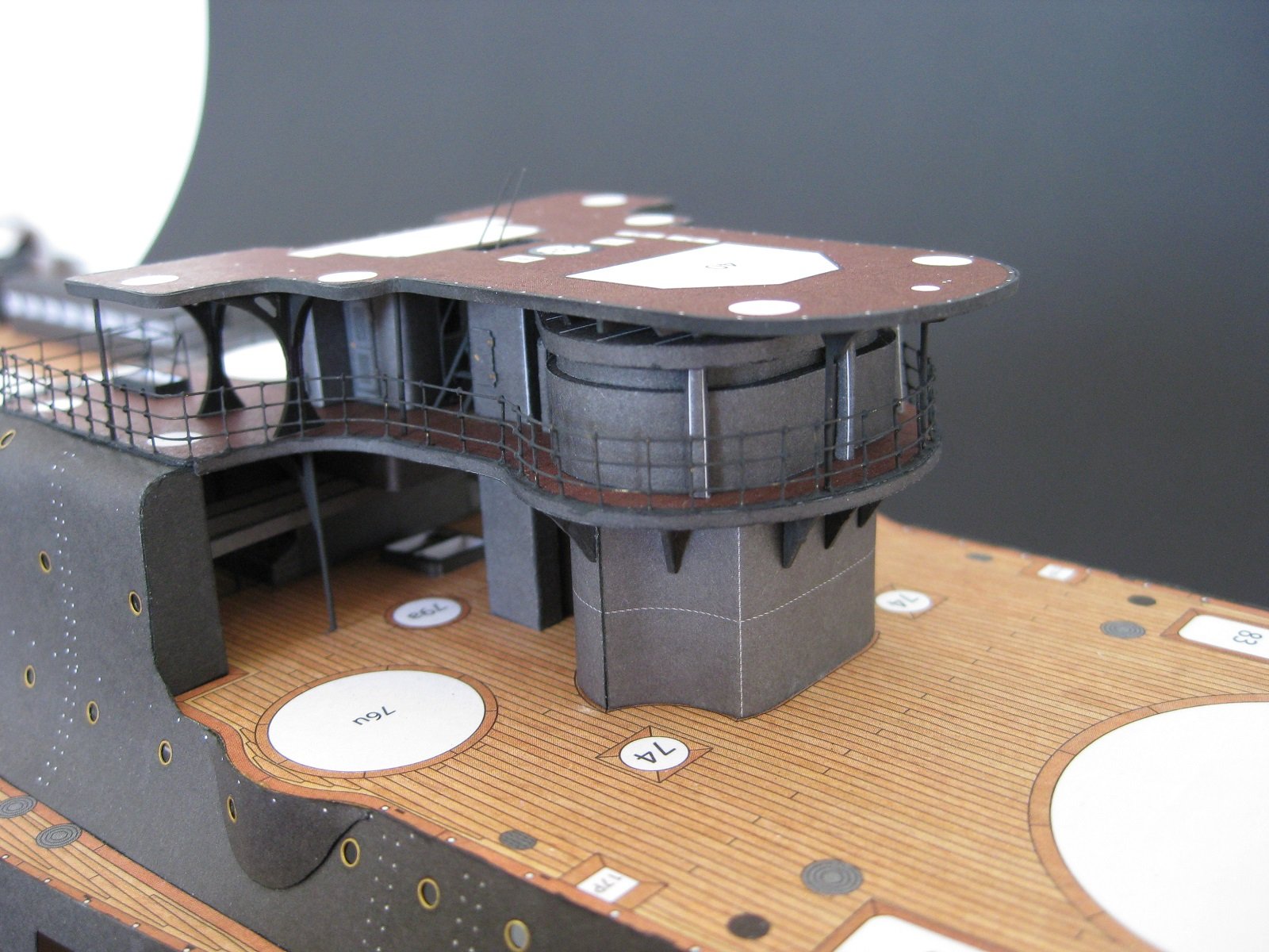
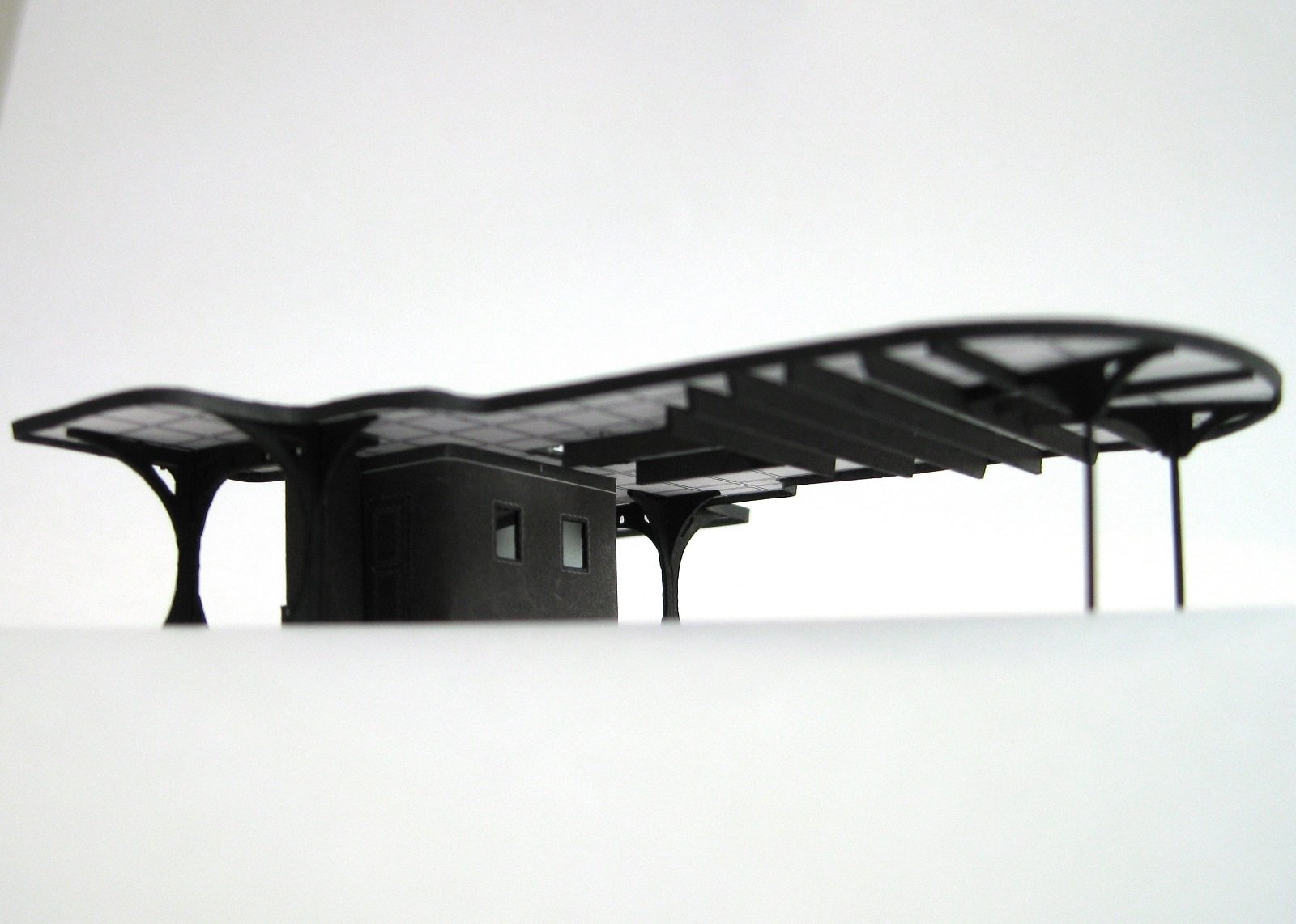
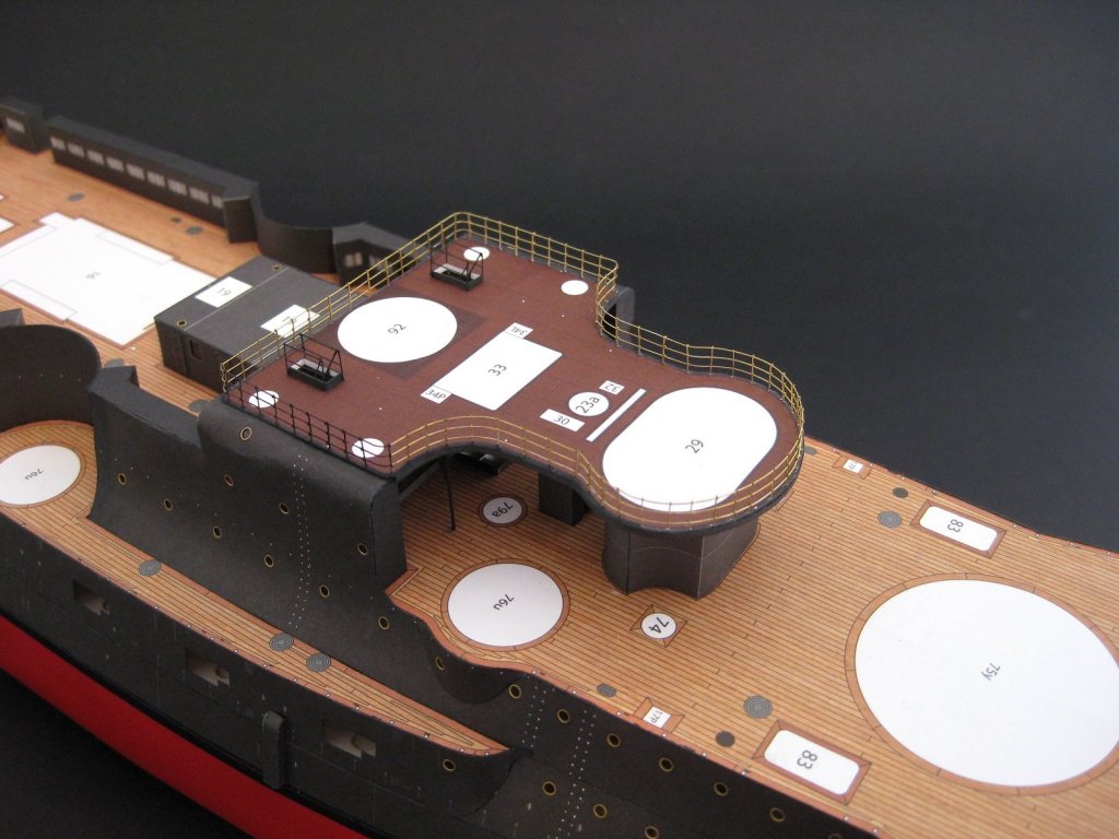
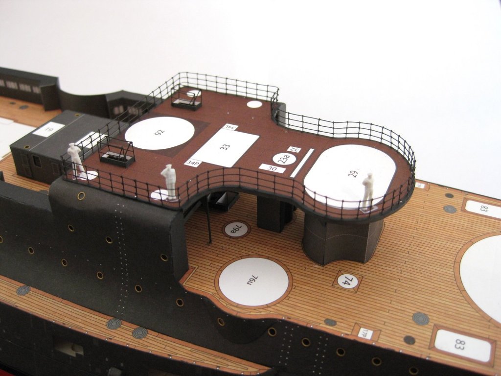
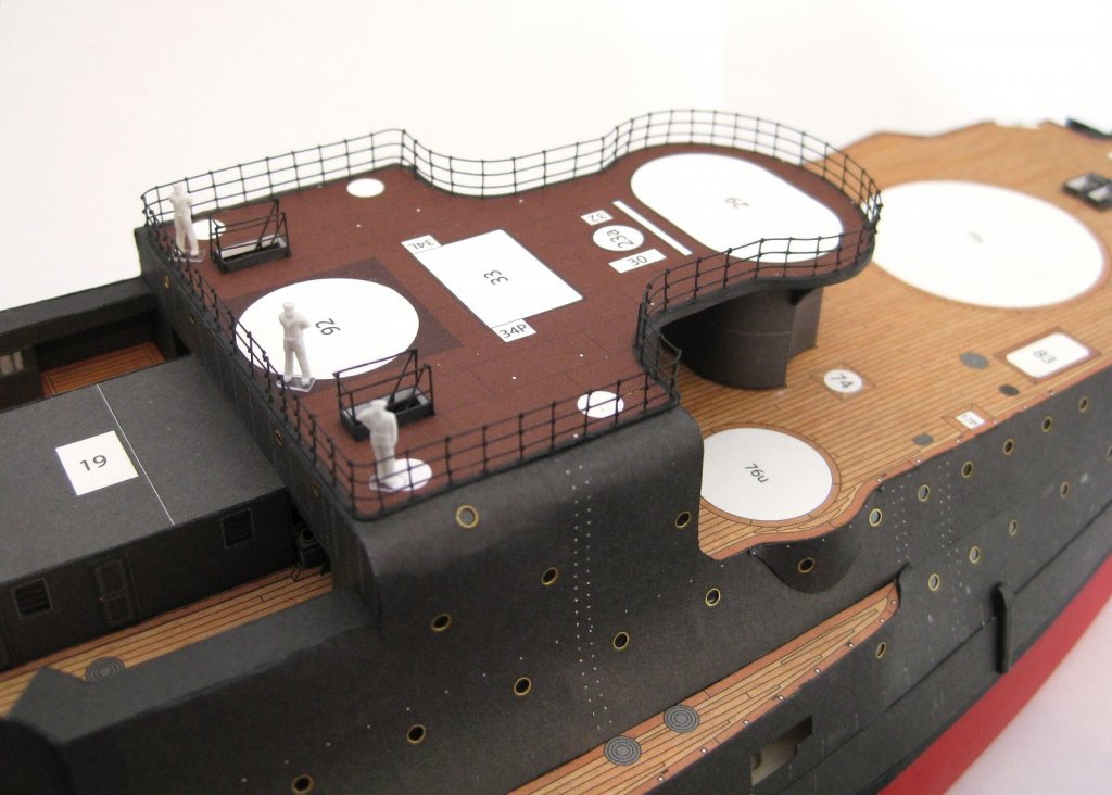
Thanks Craig for the nice comment. I always feel I could do better although on the whole I am pleased how they turned out but as usual the discrepancy has effects down the track which I will cover below. Thanks for the comment Danny, let’s just say selective camera POV hides many of my mistakes I know what you mean about being careful around finished work! In the case of the railings I caught myself a couple of times resting my hand on the ship to support my other hand with the tweezers! Hi Clare thanks for the comment, based on your work on other builds I am sure you will have no problems. Before I can continue with installing the bridge deck I need to finish a couple of bits and pieces I skipped over. One thing I missed was the stairs from the Con Deck to the bridge deck. It is official, I am the slowest builder out there taking 2 ½ hrs to make one tiny set of stairs! The handrails were as per the template but they squeeze together passing through the stairwell. Also required were 4 more 0.5mm deck supports. I painted the ends before gluing to the deck and will finish painting before flipping over to glue down. The Con deck curved railing which I was crying about being tilted inwards a bit now affects the front two supports and because of how well braced they are is preventing the whole bridge deck sliding fully forward into position. The quickest and simplest option would be to bend them back but visually would look average. So I sliced the card bracing and moved the post back and then used some scrap from the same card to fill in the gap. A bit messy but not really on view and the posts are more vertical. Time to fit the bridge deck and trialling fitting caused massive confusion! The Conning tower has white lines crossing the top which correspond to the bracing positions on the underside of the bridge deck so would mean these sit directly on top of the Con? This to me makes sense since the Bridge is directly above and if not supported below means only the front 2 posts hold the whole front end up!?! But as can be seen there is at least a 1mm space between the Con and the bridge deck bracing. So the deck needs to be level and the rear cabin, mast section and duct work are fixed heights and even if I cut them out leaving the lines on this would account for only a fraction of a millimetre too high. A double check of all the 0.5mm brass rod supports (c5 on the templates) matches the structures and the template so everything is the same height! The only other option I can think of is that the gap is correct…regardless I glued the bridge deck down; a level deck is more important than an unnoticeable (unless pointed out) gap on the underside Hmmmm never noticed the front support of the Con is askew before. Also after the photos were taken I noticed that the rear port ‘wing’ was being pushed up a little so removed the c5 brass post and filed it down so the corner sat down better. Also from the photos it would seem that it doesn’t matter how often you check and touch up the railings there are always missed bits of brass showing! I really thought I would get all 3 decks and associated railings installed on this extended swing but totally underestimated how long each railing would take and the finessing to fit the deck. Really like how the front structures are shaping up and looking forward to continuing upwards on my next swing back. Cheers Slog


- 244 replies
-
- 11
-

-
- borodino
- dom bumagi
- (and 1 more)
-
Hi Danny, great progress. I commented on exactly the same colour mismatch on my now defunct Bismarck log. Its a pity they don't review and tweek their kits periodically to fix things like that. I had some full length shots on my log showing the full deck and I had hoped at the time that once superstructures were placed the areas where they were joined wouldn't be so obvious. Cheers Slog
-
Thanks to everyone for the likes, these are greatly appreciated. Hi Craig, thanks for the comment. I know what you mean about eyesight; my close up vision has deteriorated rapidly the past few years. I often wonder if the rate is normal for getting old or if it’s accelerated due to our chosen hobby! Hi Danny thanks for the comment and links. I would have jumped at the chance to use generic rail if they had double the amount of stanchions or the ship required less. I reckon the original designer of the prototype had shares in a ship rail company LOL Saying that I do like the effect of lots of stanchions. I have come across Tom’s Modelworks stuff in the past but I always found their stuff to be more expensive than comparable offerings by others. The 3d railings look good but that price! Okay the Con deck railings attached to the deck. I started painting before remembering to take a photo. Finished finally; the below railing is the result of a total of 21hrs work! I don’t know if its just me but these are taking an age to do. Thoughts? Well they turned out not to bad for my first attempt at doing railings but as usual lots of room for improvement. Two stand out items; firstly the join for the railing ends on the rear run is pretty rubbish but due to its position can live with it. Secondly and most annoying is the front curved section, which was pretty much spot on when originally done and was very happy with it but…doing the last run on the port side straight section required a fair bit of pushing and pulling to get in to shape. Only after final gluing did I notice the port side of the curve section leans inwards a bit…enough to keep drawing my eye to it. Oh well. Next up to glue in the previous made components to the Con deck so the bridge deck can be installed and railed up. Cheers Slog
- 244 replies
-
- 15
-
-
- borodino
- dom bumagi
- (and 1 more)
-
Let me be the 1st to congratulate you on a very nice build. Well done it looks fantastic, look forward to following the Bismarck. cheers Slog
- 295 replies
-
- 4
-
-
- amatsukaze
- halinski
- (and 2 more)
-
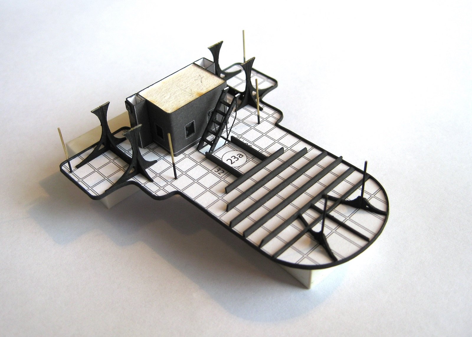
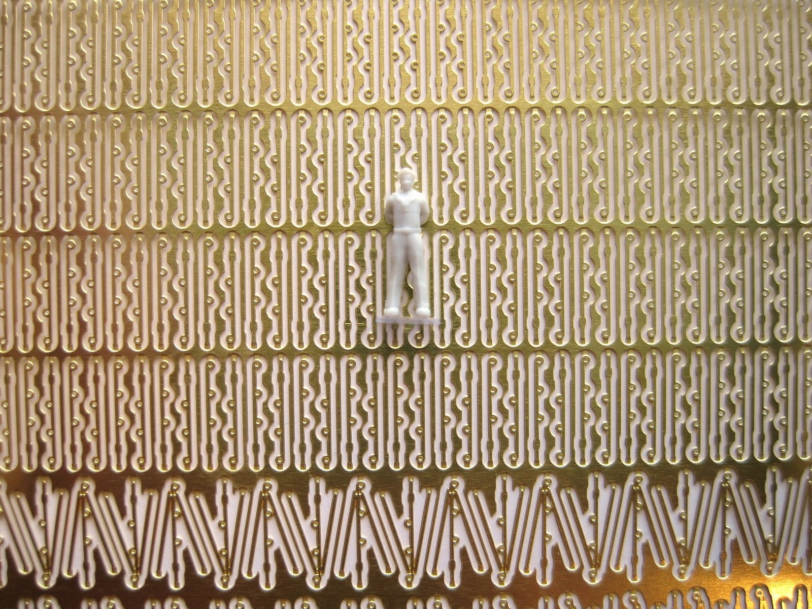
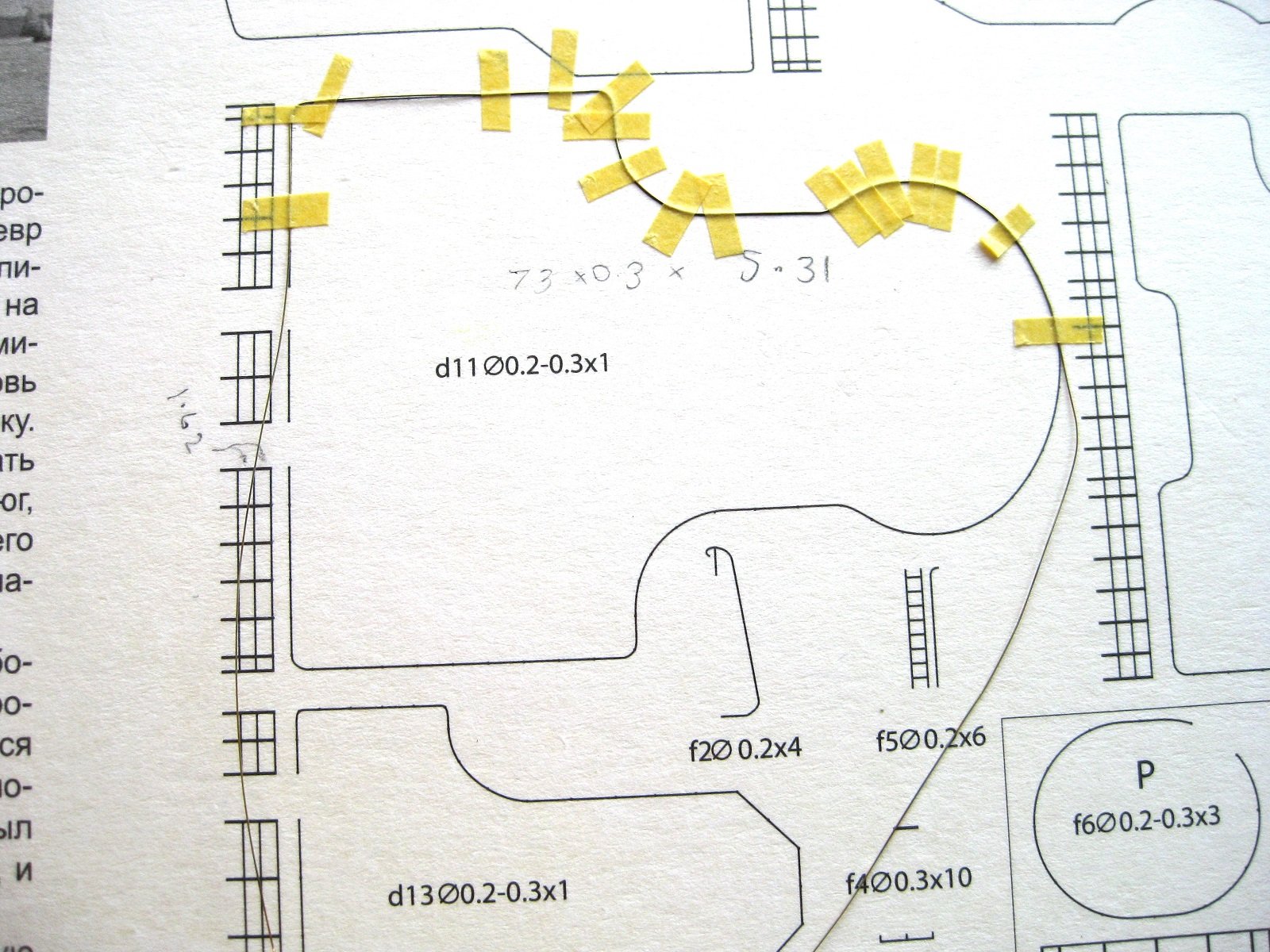
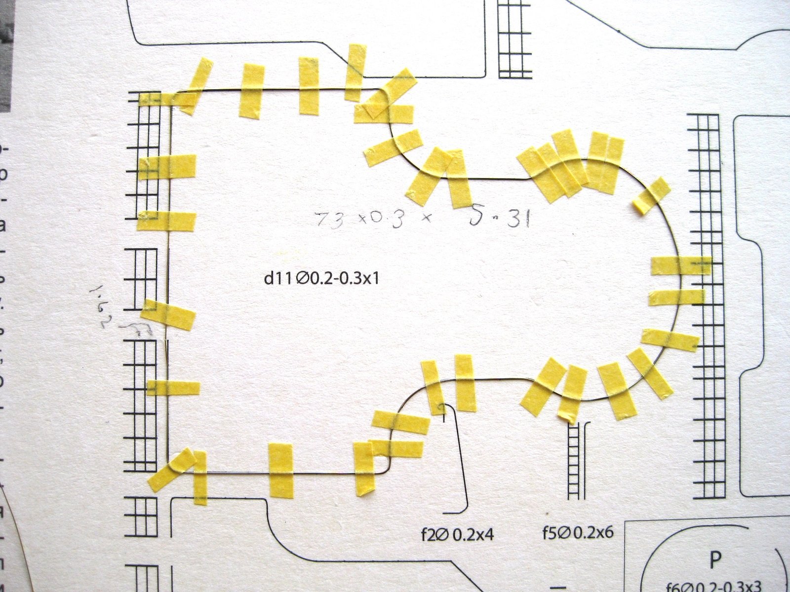
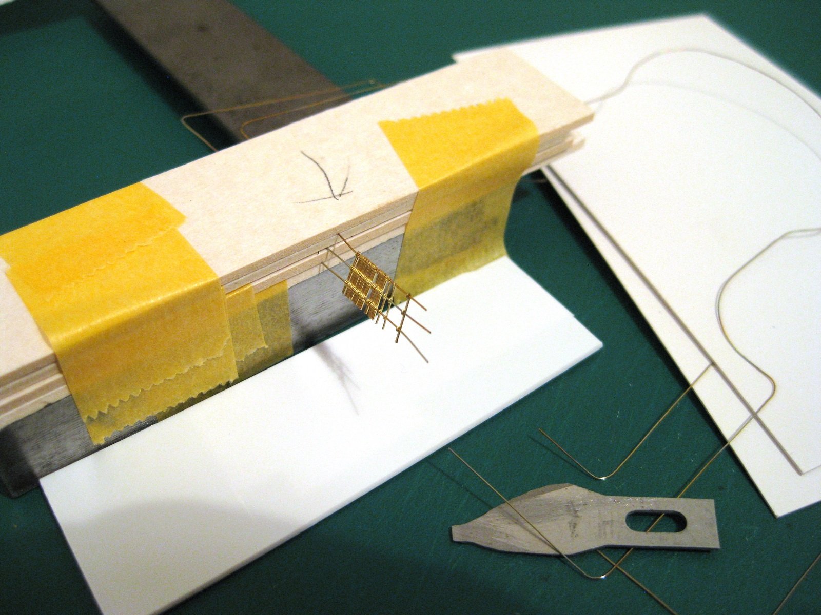
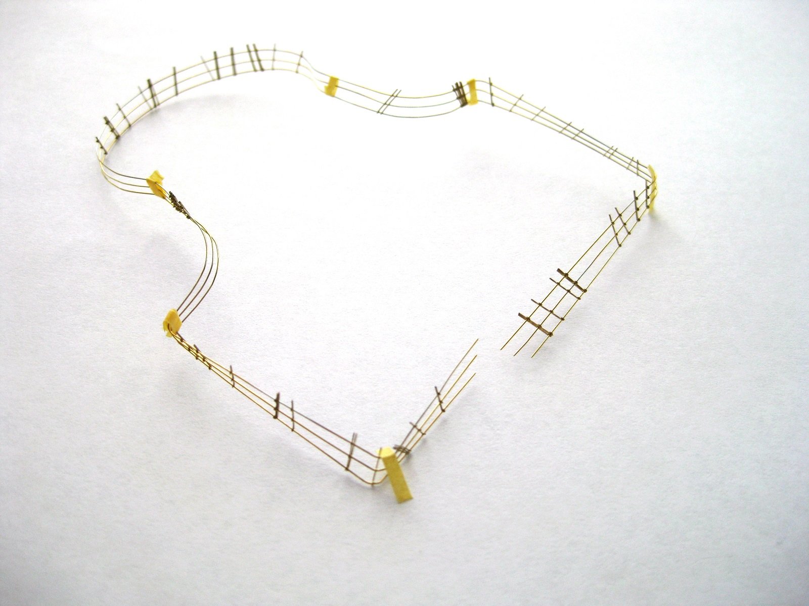
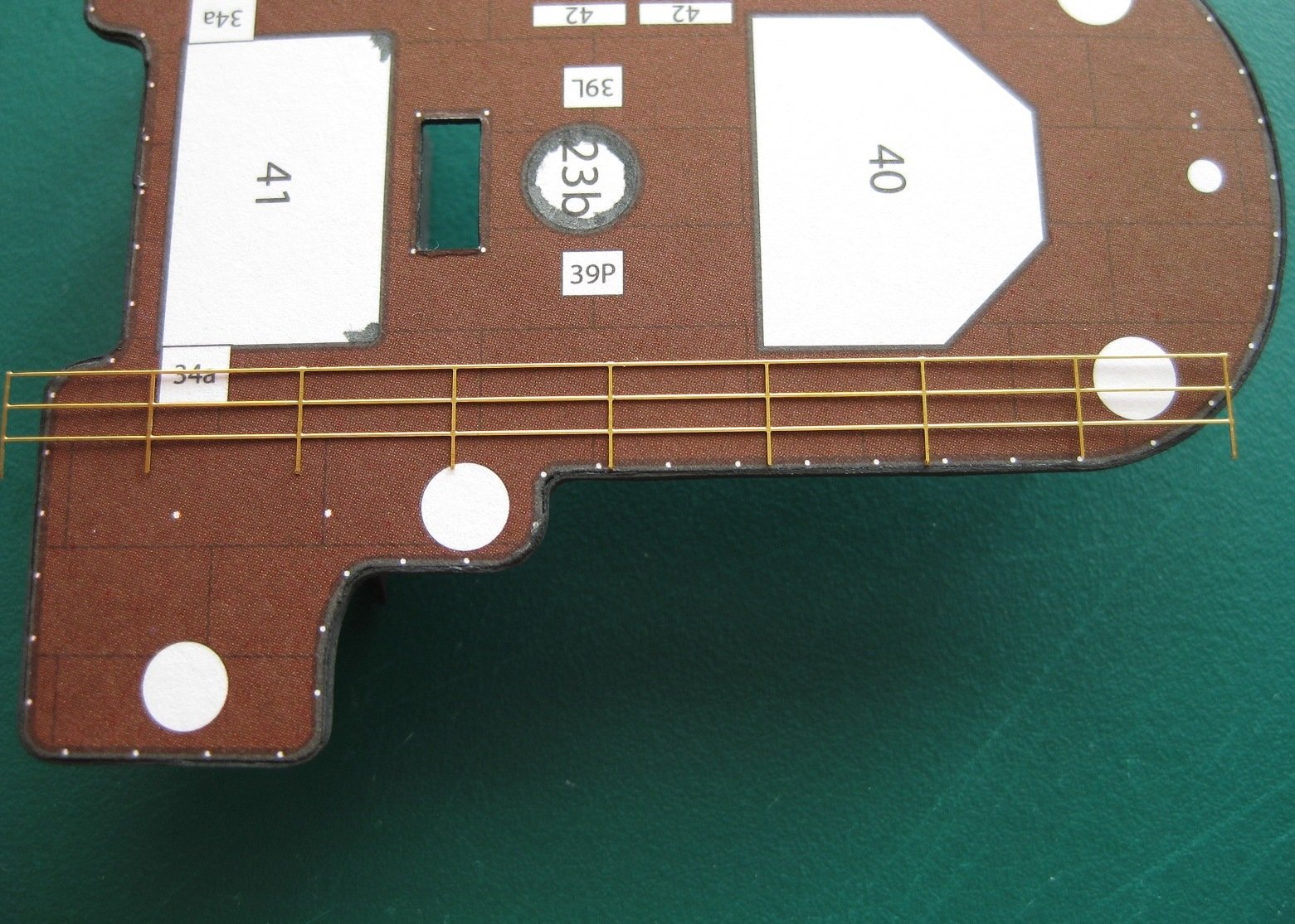
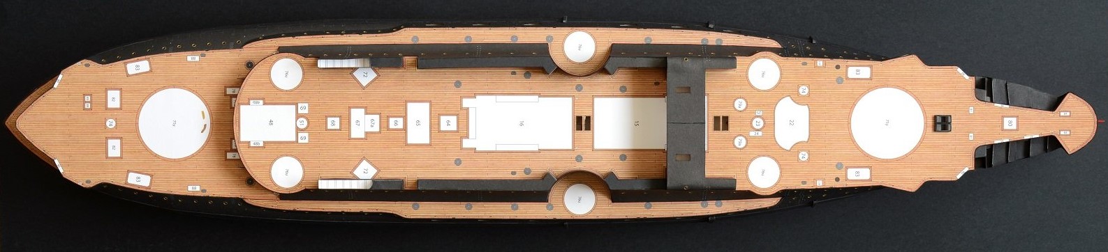
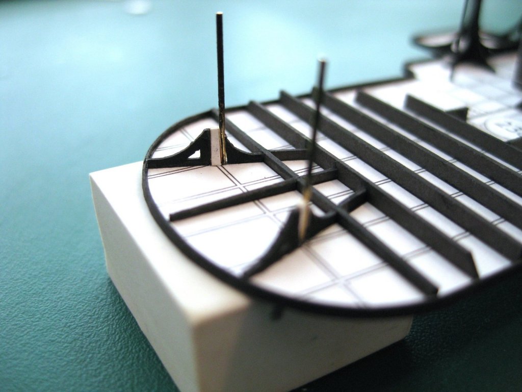
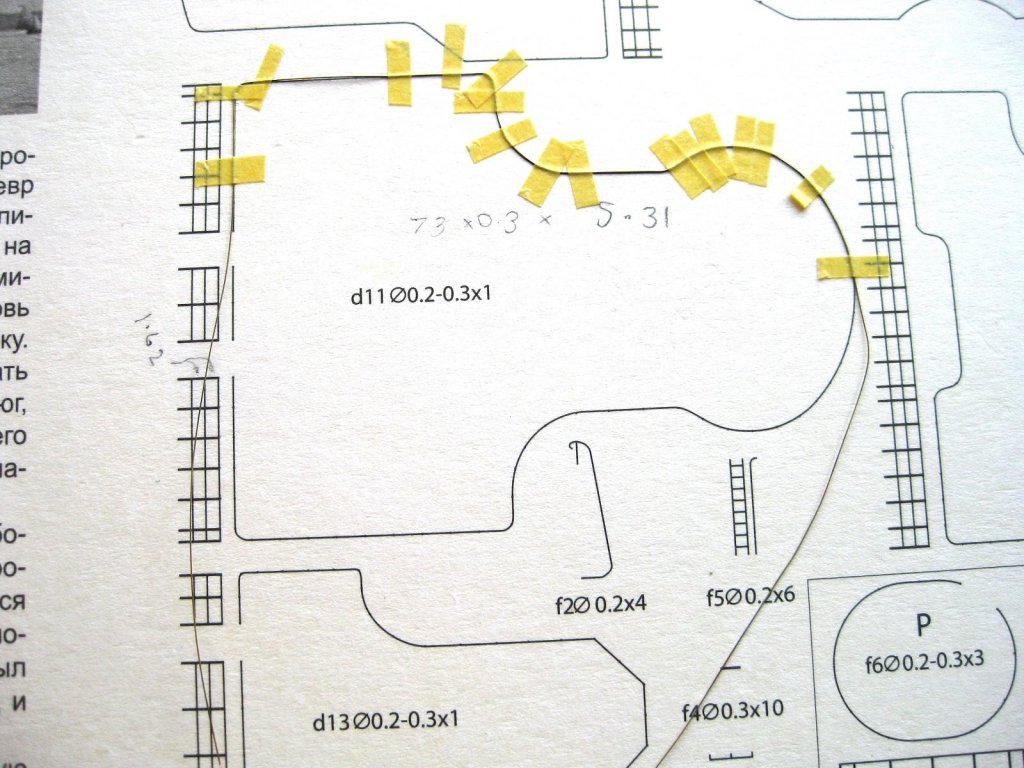
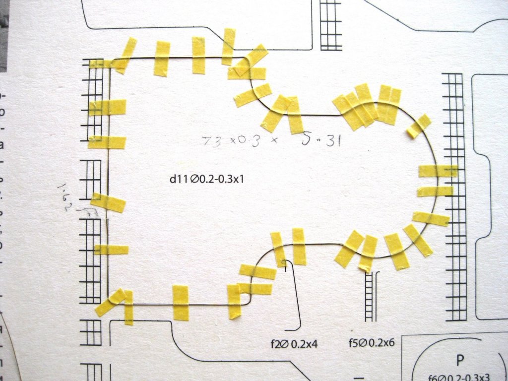
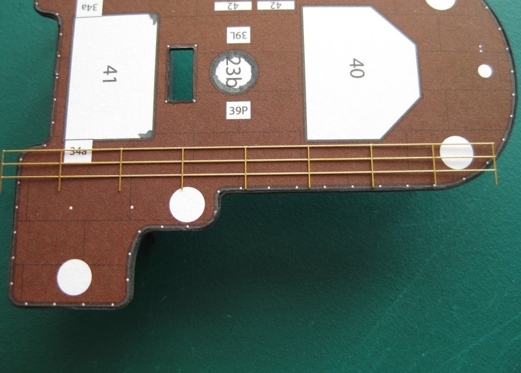
Hi, thanks for all the comments and likes. I am now in a position to do the deck handrails. The quickest and simplest method would be to use generic 3 rail photo-etch but as can be seen in the photo below the spacing of the stanchions are at least half of what is required and miss every post location. Since I really like the look of the high ‘density’ of stanchions this didn’t appeal to me. The other option would be to do as the plans suggest and use 0.3mm wire as stanchions and 0.2mm rails and build them up individually. I started to do it this way and began cutting dozens of posts, when I came across a build where the guy used individual photo-etch stanchions and I decided this would be easier (?) and still look good if not better for the desired effect. I preferred the style of the other guys stanchions where the rails run through the centres of the posts instead on the sides like the ones I got but the effect should still be good. The stanchions were also a bit high if left to length with the small rectangle section at the base, which I don’t like so cut this off. I used the kit suggested 0.2mm wire after checking it fit through the holes and this was formed to shape as per the template. The wire I have is very stiff and springy so I annealed it first and then starting from the front middle curve began forming it on the provided template. I would fix a section down with tape and then form to the line below; once the wire stayed in placed without holding it down I then taped that section and progressed round like that One rail down, another two to go for the first deck. Once the 3 rails were shaped I taped them down to my square to keep them raised for access and to separate them roughly too width. The photo shows the first lot from a total of 72 stanchions being slide onto the rails. I staggered the ends slightly to make it easier to thread one hole at a time whilst sliding them on rather than try and line up 3 together. I also placed card between each rail to separate them as they had a tendency to tangle up. It’s like herding cats trying to keep them in some kind of control. I know it looks like the aftermath of the Battle of Tsushima but it is still very flexible as the rails are free to slide along the holes in the stanchions. I grouped the stanchions into sections, counting out the required amount and then placing some tape to keep them separate. Okay the first 2 small sections glued down. This has to be one of the most frustrating things I have ever done! These 14 posts took 1 ½ hrs to do and from the photo I think its fair to say pretty obvious this is my first time doing any significant railing. It least this ship gives plenty of practice for railings. Although slow progress I am pleased enough how it is shaping up and once painted should just blend in to the overall appearance. Speaking of painting, I consciously chose to do it after installation. Before or after both have pros and cons but for me after should be better. That’s it for this swing but will be back for 5 days next time round so the goal is to get all the fore decks done and finished off so I can rinse and repeat for the rear decks. Cheers Slog


- 244 replies
-
- 11
-
-
- borodino
- dom bumagi
- (and 1 more)
-
Hi Rony, That is a very nice, clean build. A bit more information like scale, publisher length etc would be interesting. Cheers Slog
-
Looking good. I like your make shift jig to hold everything in alignment. Cheers Slog
- 295 replies
-
- 6
-
-
- amatsukaze
- halinski
- (and 2 more)
-
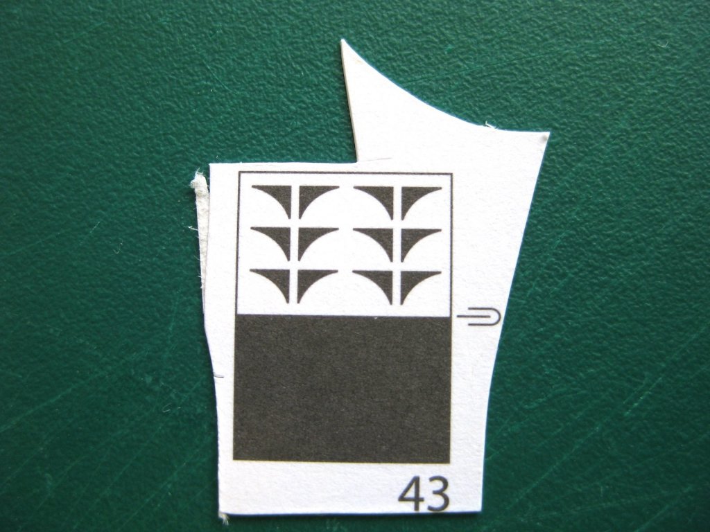
My guess is the publisher has just filled in the blank space between parts with a colour 'swatch' which can be used to make repairs or patches. Some publishers do this, others don't which is a pain as it means trying to colour match any repairs. Usually big enough to make at least one full size replacement part though.
-
Very nice Craig, looking good. I am curious, did you use the suggested paints in the colour callout as I don't have much experiance on paints. If I remember correctly the suggest paints and brands said they were semi-gloss; I wonder how they look in real life. Cheers Slog
- 467 replies
-
- 6
-
-
- mikasa
- wave models
- (and 1 more)
-
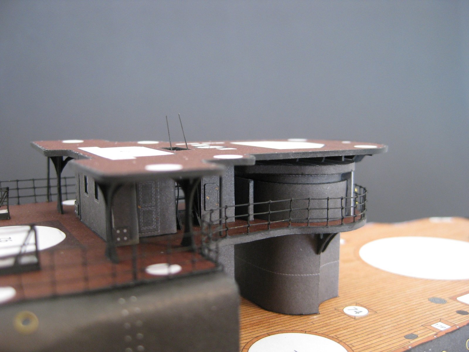
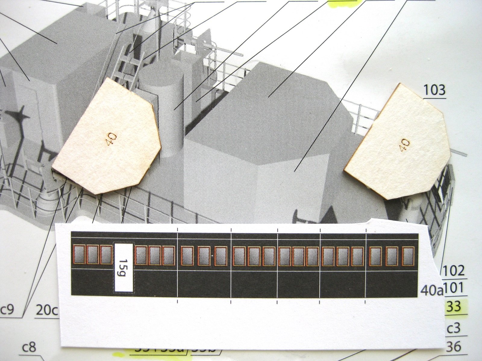
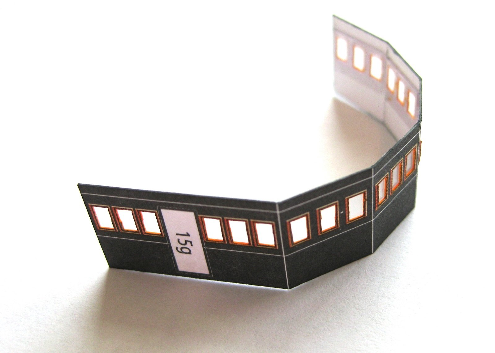
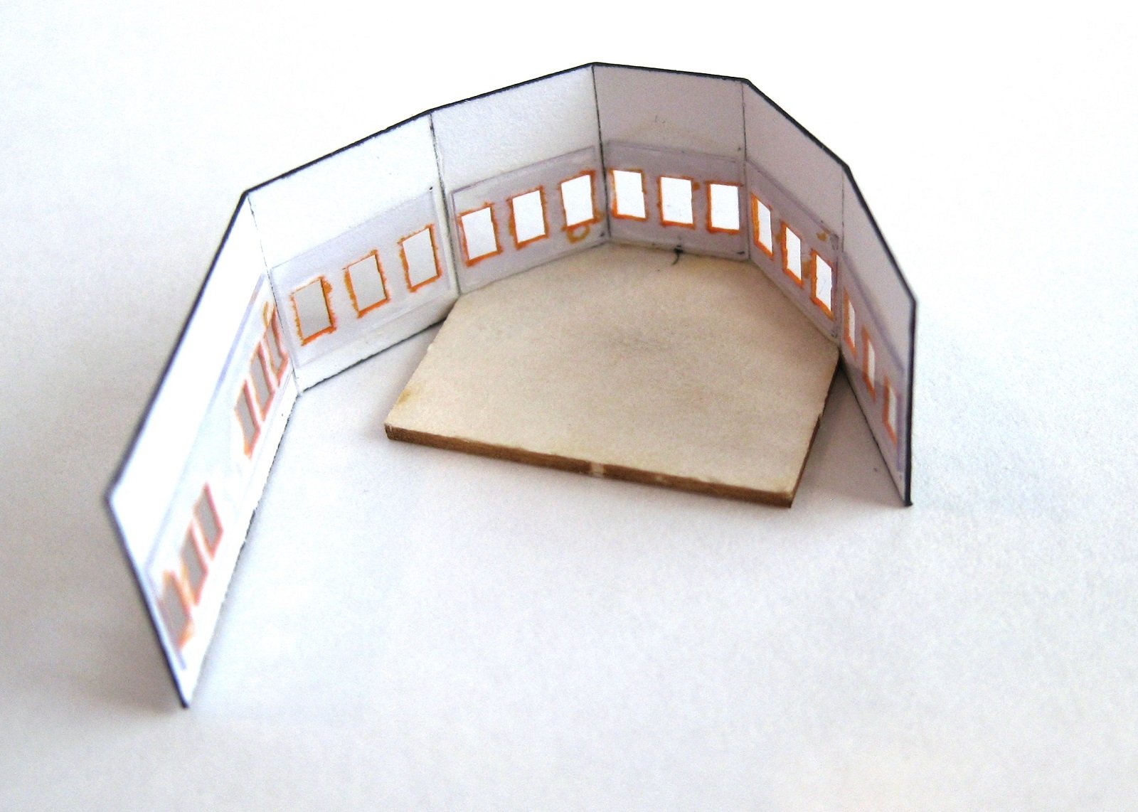
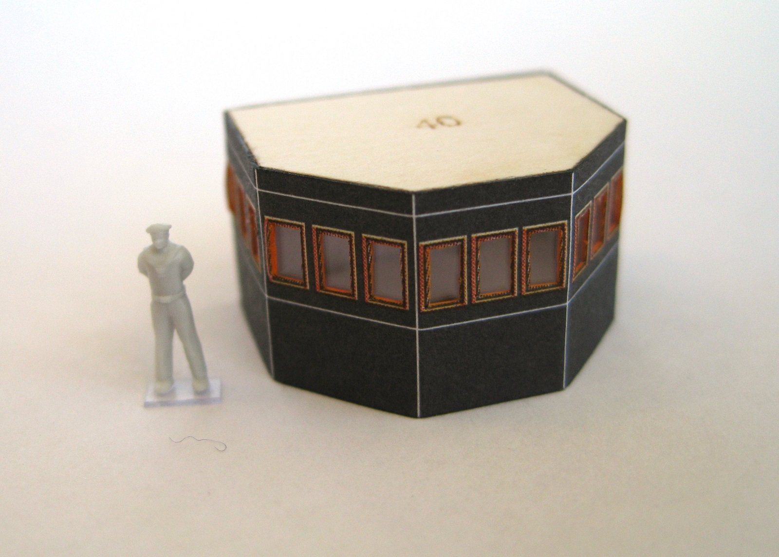
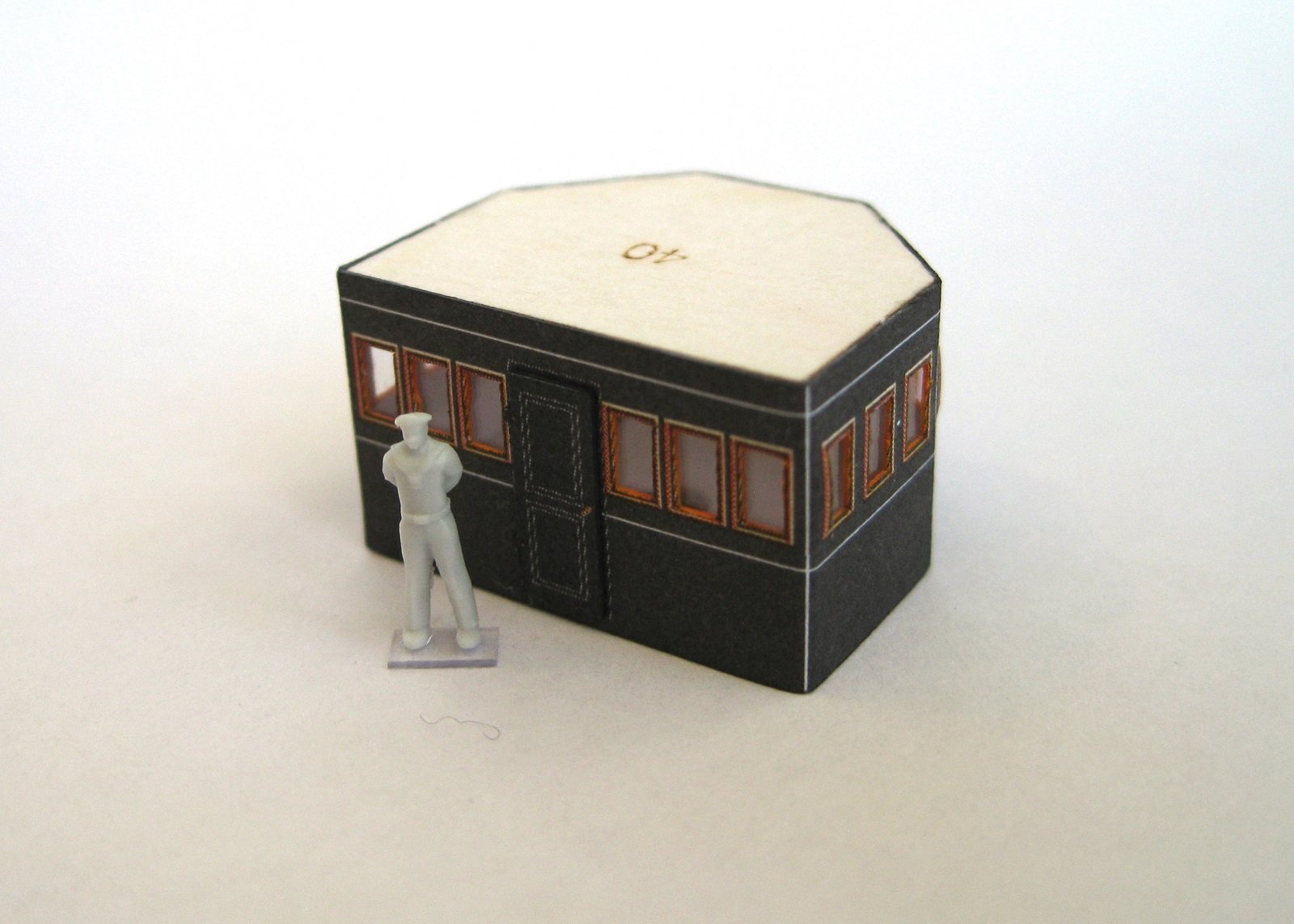
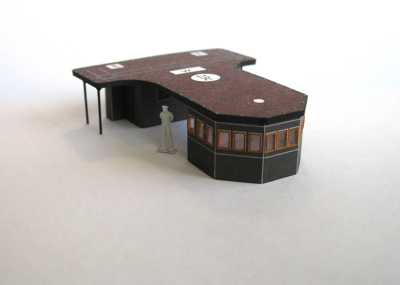
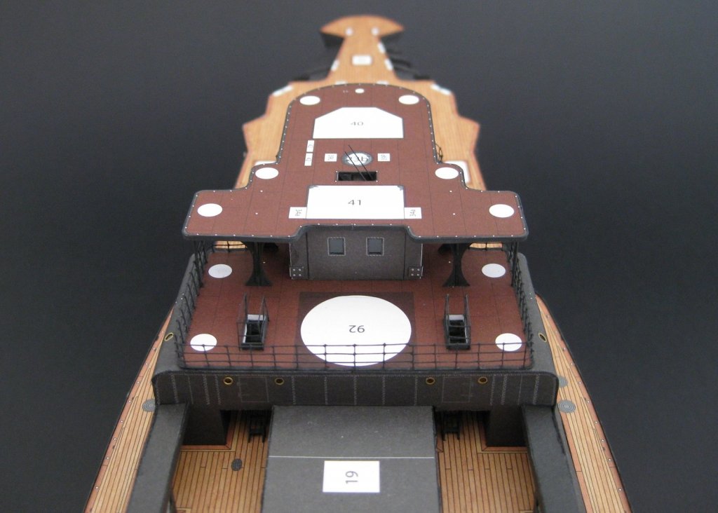
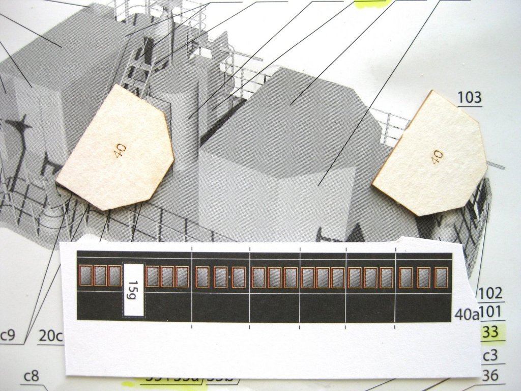
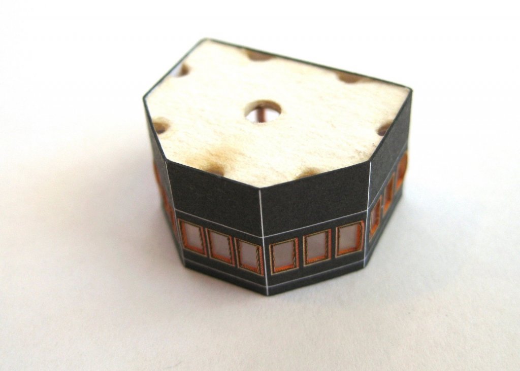
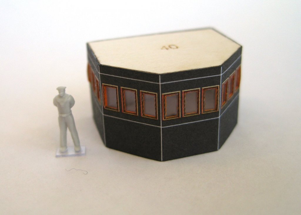
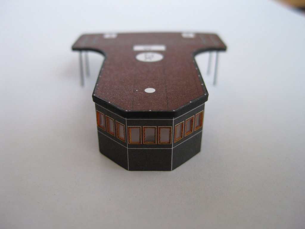
Hi Danny, thanks for the comment and I totally agree these are the fun bits and thanks to everyone for the likes. Bit of a boring post this time as it all just more of the same. Photo below shows another rear cabin and another couple of service ducts with hatches and another mast section similar to the deck below shown previously. Incidentally they are slightly shorter than the previous ones. Next is the bridge with only 4 parts, the wall, a door and top and bottom laser cut forms. These caused a bit of a dilemma. For the other cabins with only tops and bottoms I could pack them out to the correct height as the insides wouldn’t be seen. Since I wanted to cut out the windows and replace them with clear ‘glass’ I couldn’t pack them out as the windows go all the way round. This required a bit of head scratching on the best way to tackle this. The windows were cut out first followed by trimming the element to size. Following this I scored and marked the bends on the inside of the part and then glued in the ‘glass’ whilst it was all flat. Once that was done I pre-bent it roughly to shape. I decided to glue up one complete form rather than try and do top and bottom together. I also thought doing the top former was the way to go but, either or, should work. I held the top former down on a sheet of glass and worked from the front section and alternating from side to side to finish with the long back section. I did it this way to reduce errors compounding if starting from one end. Now that the top perimeter was glued to the form and the joining edges glued up I had to get the bottom form in to place. Firstly I made a hole in the centre so if it got jammed in during trial fitting I could hook it out. To make sure it was a nice fit and didn’t risk damaging the bottom edge or bulging it out, I carefully sanded the edges and trial fitted it several times until it could be pushed in comfortably. Once it fitted well I hooked it back out and punched some holes round the perimeter. This was so I could get a glue bond after it was fitted. It was too risky (IMHO) to apply glue firstand then try and refit the former. It worked out well. Couple of photos of the finished item. Really happy how it turned considering how apprehensive I was doing it without the packed out forms. On to the last top deck. Same deal as the others, top and bottom parts to glue together followed by a perimeter strip. The underside also has some posts with bracing as shown below. Since I was used to using laser cut forms for bracing I hunted through the parts sheets and the forms looking for them for an age. Finally found them and are a simple fold together part with no laser cut substitute. Since they are tiny I cheated a bit and once folded and glued I cut the horizontal and vertical side first and then simply made a straight cut between the 2 points. Finished top deck with the perimeter strip, posts and braces in place. The simplified braces can be seen here but once right side up and in place they won’t really be seen. Just to touch up the perimeter strip, posts and braces with some black watercolour. Finished bridge and top deck. The bridge fitted perfectly within the perimeter strip and on the whole pretty happy with it all. The eagle eyed among you will notice I haven’t cut out the stairwell yet ‘W’ This was an oversight and didn’t notice until I was getting ready for the pictures. I did the exact same thing with the con deck below it! Shouldn’t be an issue to cut out later. I am still have the stairs and railings but holding off for the time being due to some issues which I will cover when I do them. Until them I will continue to make assemblies as per the part number sequence on the plans. Cheers Slog


- 244 replies
-
- 13
-
-
- borodino
- dom bumagi
- (and 1 more)
-
Great looking subject Jan, I look forward to following along when you decide to make a start. Cheers Slog
-
Hi J, You are making nice progress. RE you question about the lines showing through; ideally the hull ribs, bulkheads should be faired similar to what would be done with a wooden POB hull. Cheers Slog
-
Beautiful work Grant. Hope you show some photos of the 'sea trials' Cheers Slog
- 339 replies
-
- 5
-
-
- dumas
- Chris-Craft
- (and 3 more)
-
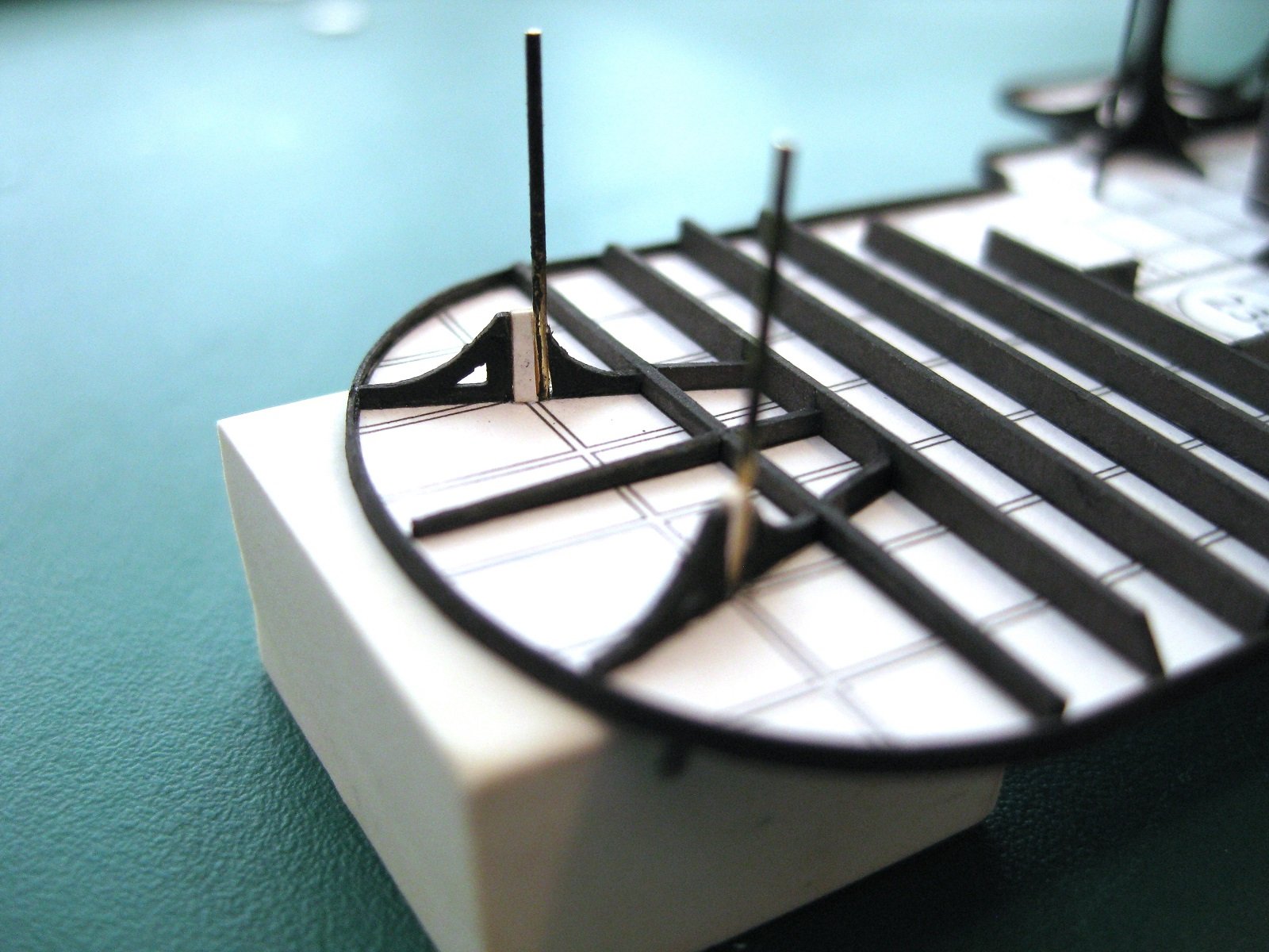
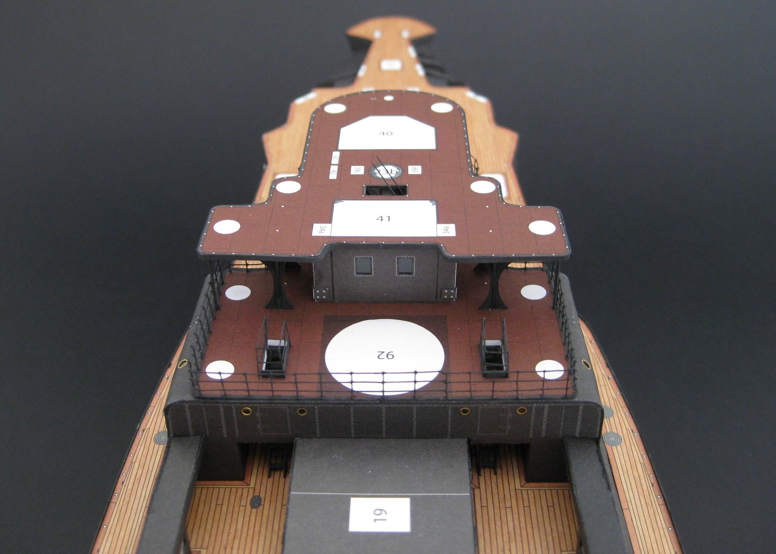
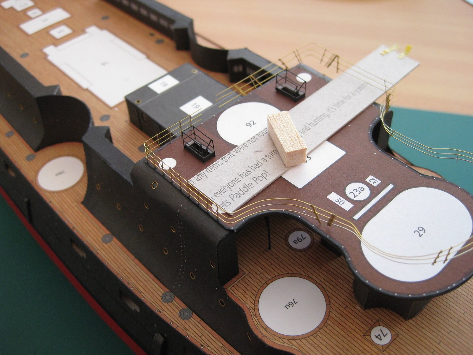
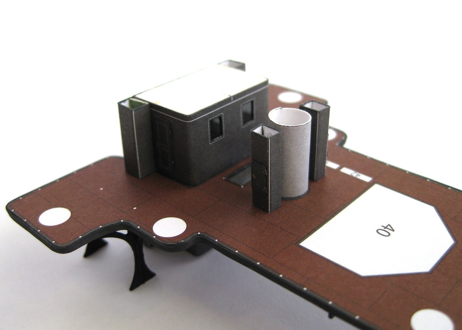
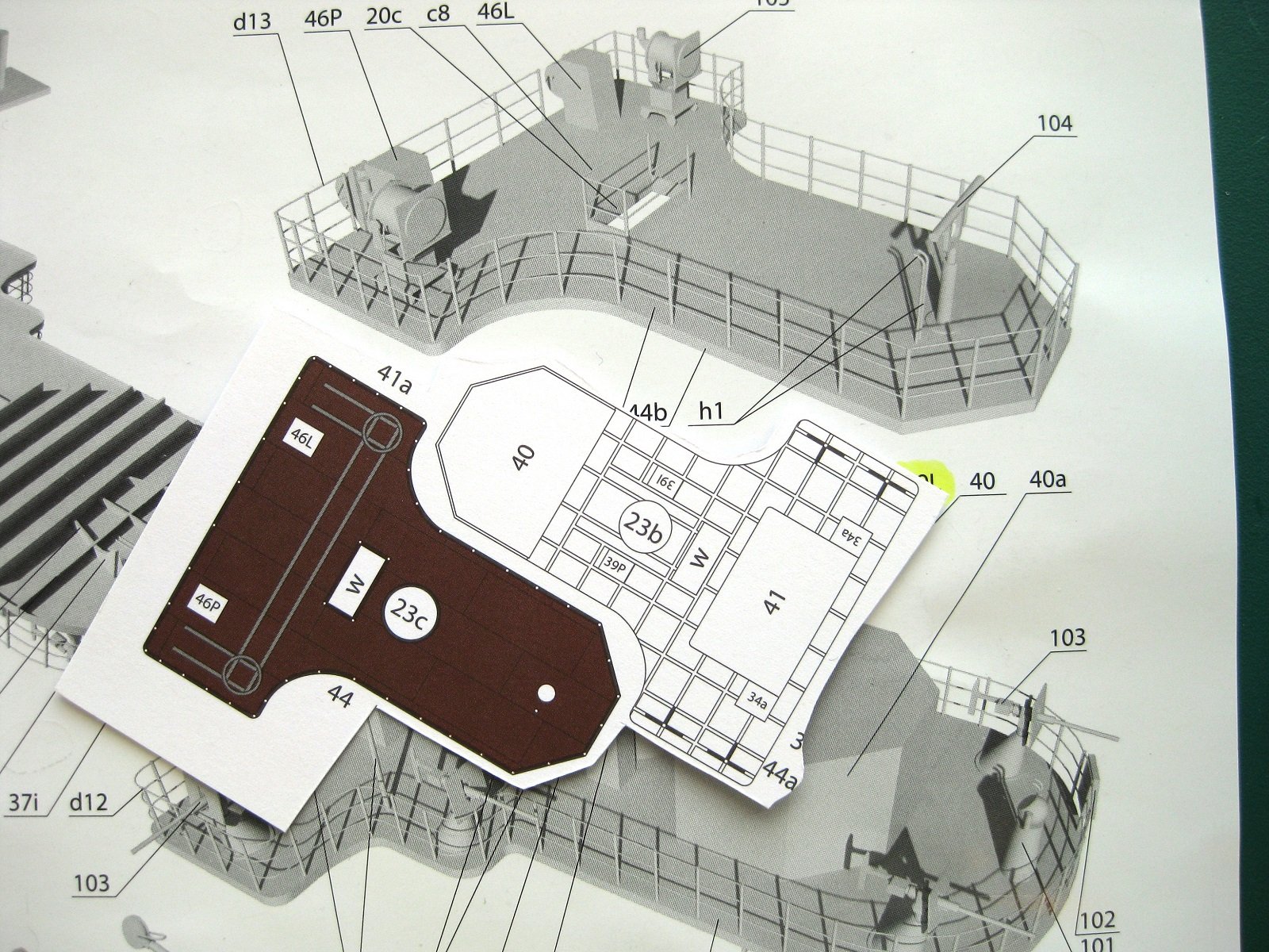
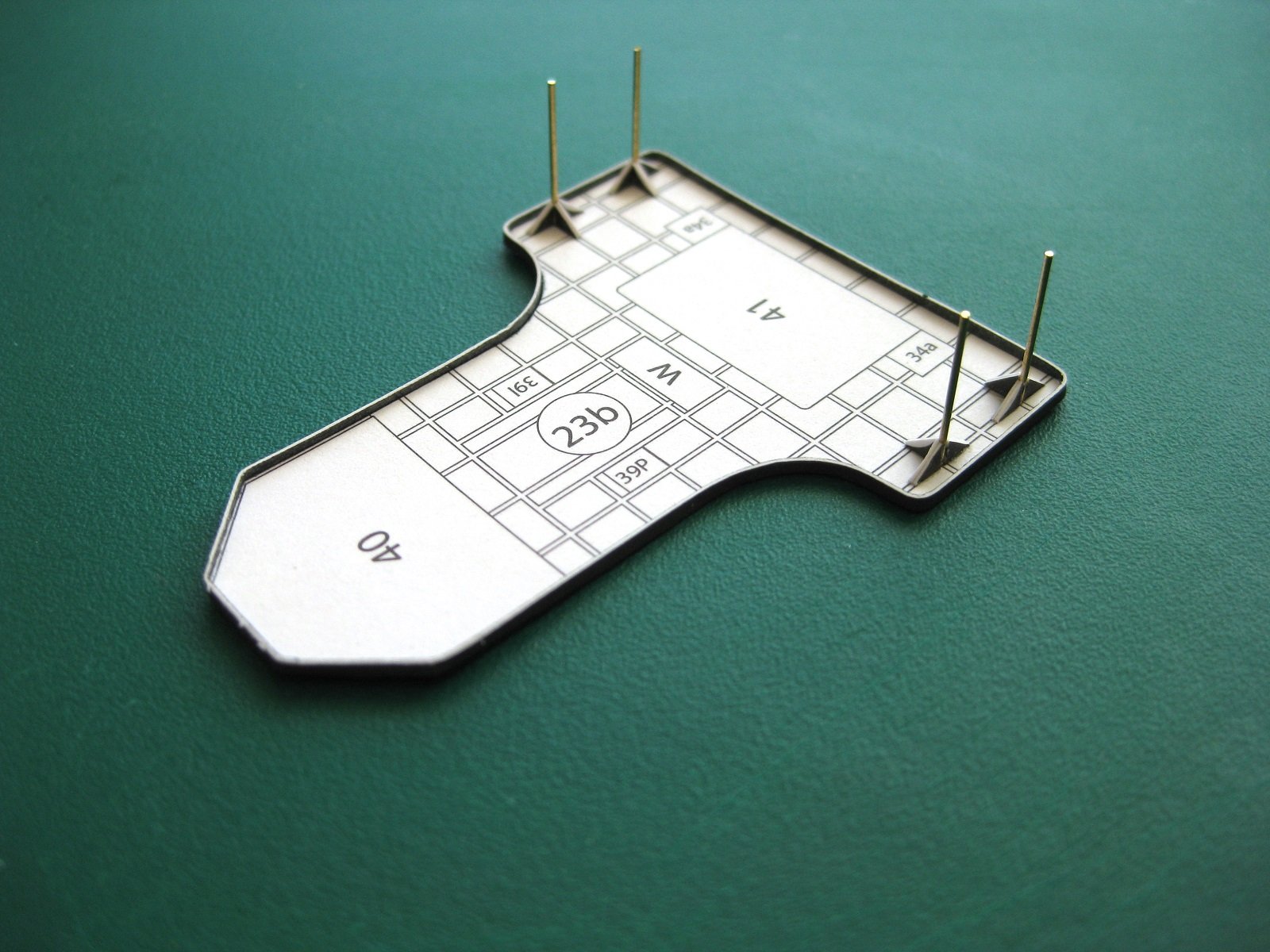
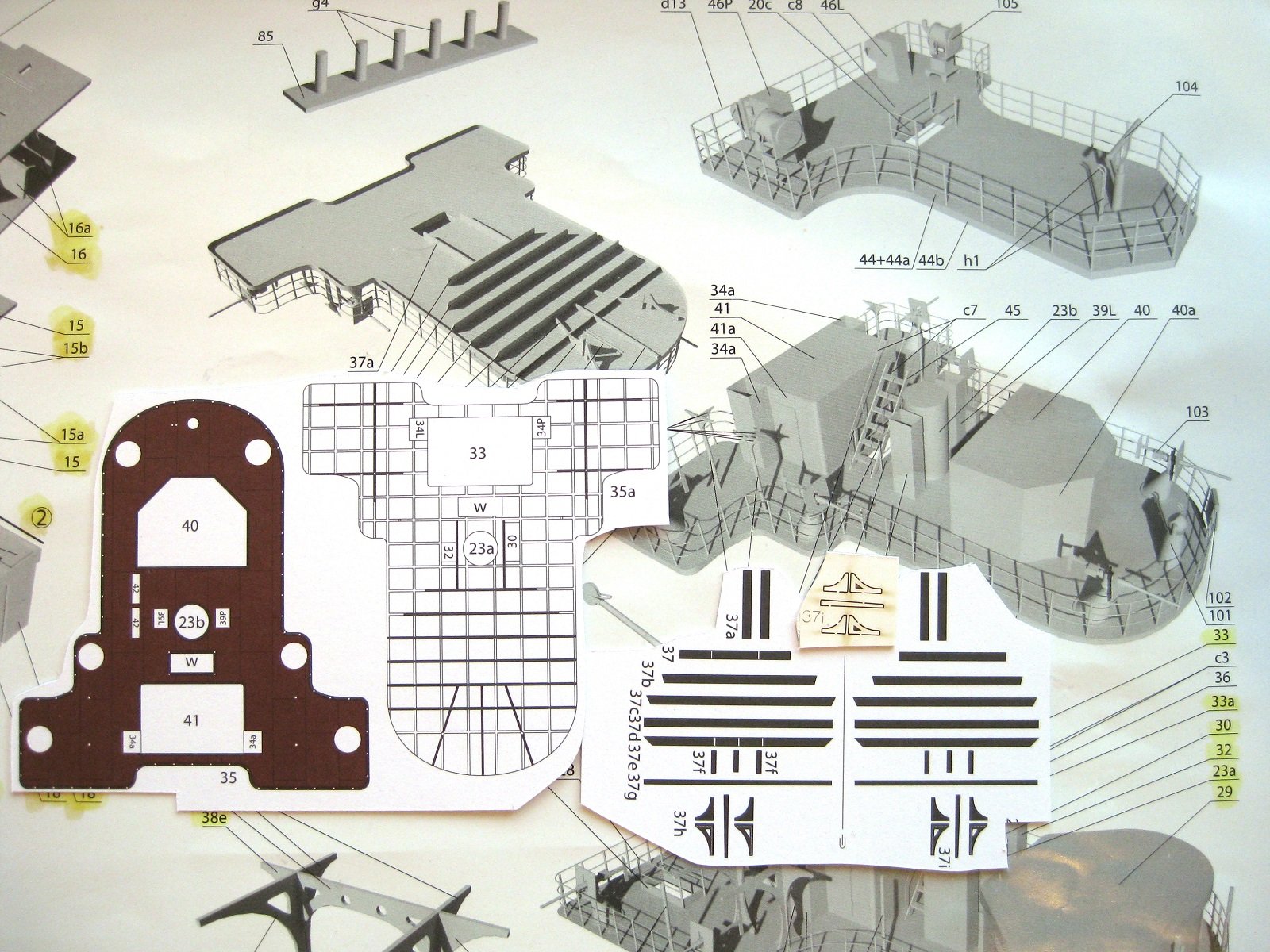
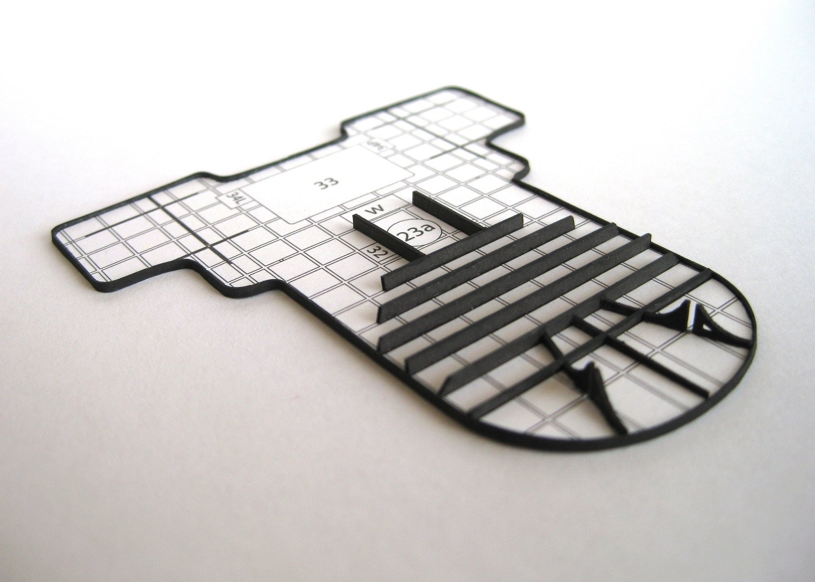
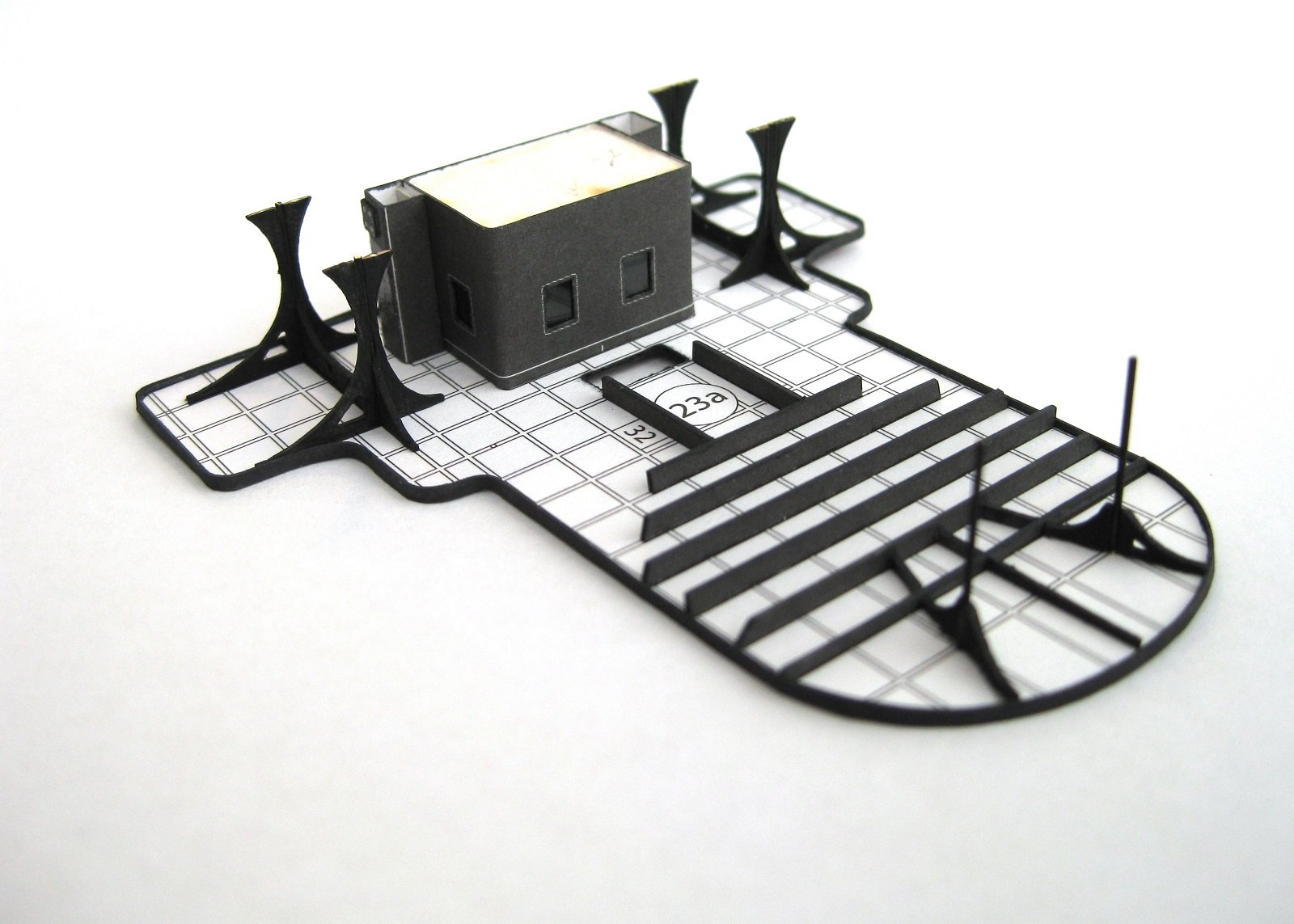
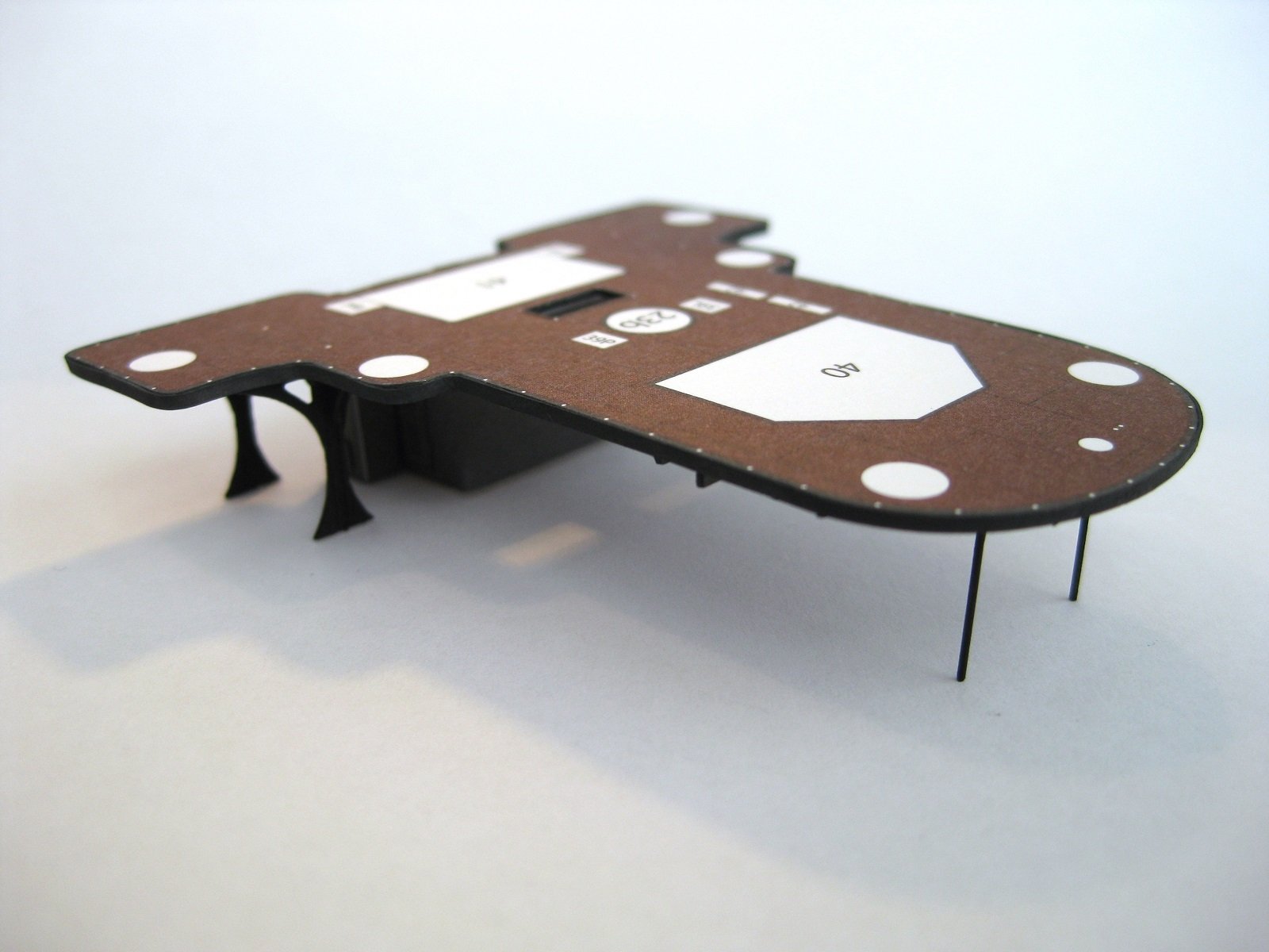
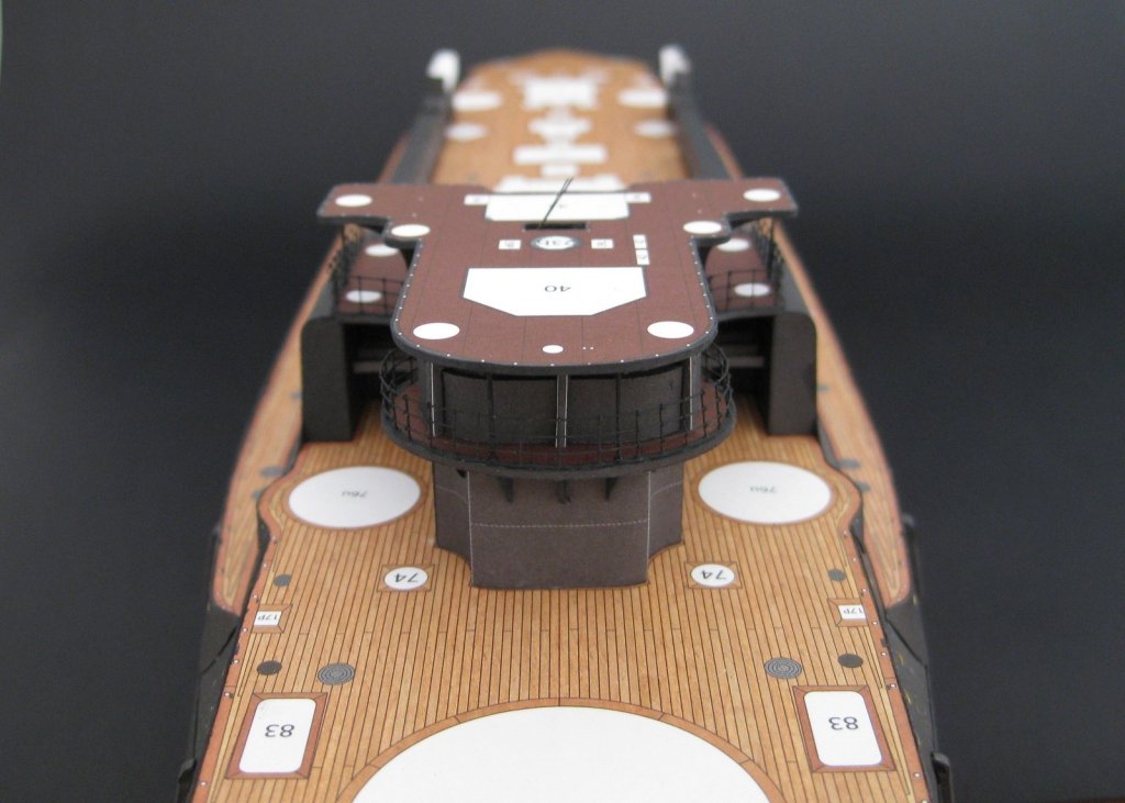
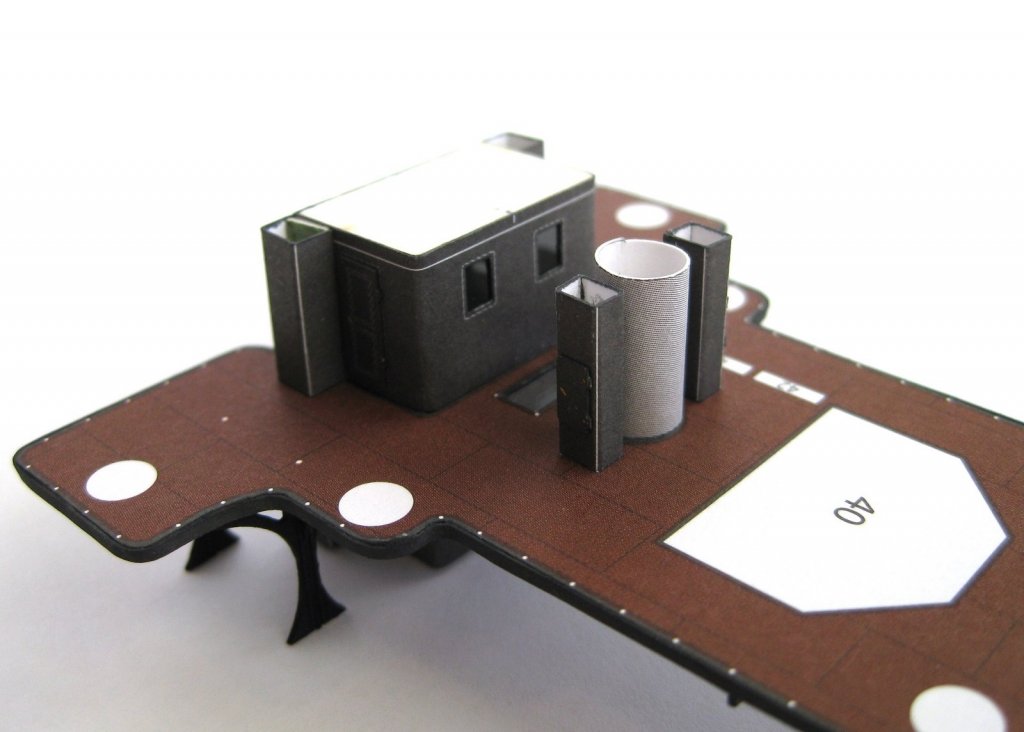
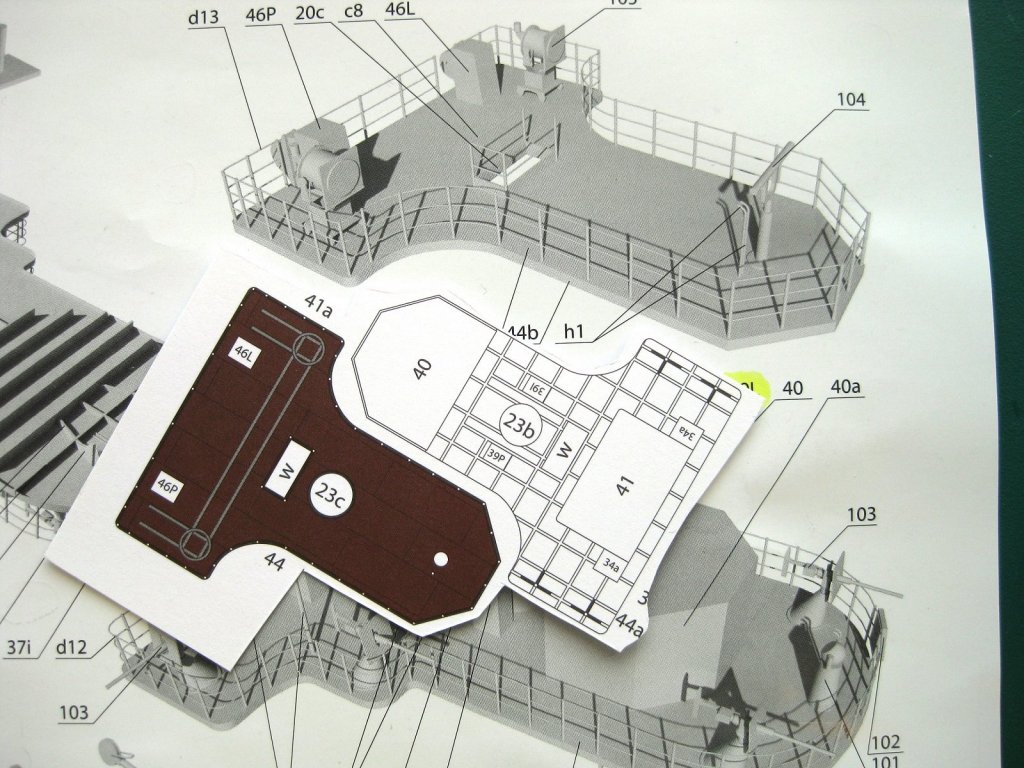
Hi, A small bit of progress. Whilst I decide the best way to do the railings on the Con deck (and the rest of them) I decided to continue on with the next level which is the bridge deck. Similar construction to the lower deck with an upper and lower surface and a perimeter strip (not shown). The difference with this one is all the bracing on the underside. Again substituted the small braces for laser cut forms. There are a lot of elements on this deck including a rear cabin the same as previous and of course the bridge itself which is the angular structure in the plans and the unprinted area it fits. The elements from the above photo fitted in position. Same as previously done for the Con deck. For assembly of the stack of decks I looked at the different options and what would be best/easier etc and decided in this case to add some Con deck items to the underside of the bridge deck. The bridge deck ready for more structures; especially looking forward to doing the bridge (location 40 in the photo). After seeing this photo on the computer I thought the front supports were messed up but didn’t notice when taking the photo as they are supposed to be vertical. Turns out they do bend back slightly but not as much as the photo shows and due to a slight hump in the middle of the deck they will straighten out when fixed to the Con deck below. Cheers Slog


- 244 replies
-
- 10
-
-
- borodino
- dom bumagi
- (and 1 more)
-
Hi jct, I have had great results with Faber Castell PITT artists pens despite what others say. I was directed to them by other card modellers. They are are quick and easy to use, don't need to worry about getting it where you don't what, don't bleed, dries immediately and edge colour before joining as they don't effect the glue joint. Saying that I also use watercolours and acrylics although I didn't like watercolour pencils. Try a few different options and see what works for you although you may settle on a couple depending on the task at hand. Cheers Slog
-
Hi jct, I will follow along also, although the subject isn't my usual area I enjoy watching card builds come together. Cheers Slog
-
Hi Craig, Nice steady progress, enjoying following along. RE the colours I had the same dilemma, as I also prefer the earlier black and striped funnel colours. Hadn't heard of the all grey scheme. The colour pull out in my kit shows grey topside with oxide red lower hull which is the 1905 Battle of Tsushima colours. When I get closer to building this one I may buy the Orel 1:200 card kit of the Mikasa to use as a colour reference as this kit is in the earlier black scheme. looking forward to more. Cheers Slog
- 467 replies
-
- 6
-
-
- mikasa
- wave models
- (and 1 more)