Keith Black
-
Posts
6,728 -
Joined
-
Last visited
Content Type
Profiles
Forums
Gallery
Events
Everything posted by Keith Black
-
 No doubt, Keith. I was just thinking out loud about the wheel design and wondering if there was a slight glint of reason behind Engel's madness.
 -
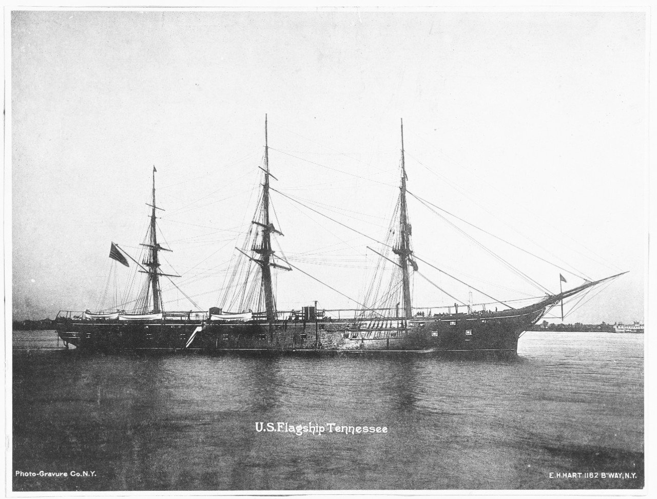
I'm measuring and laying out where everything goes on the hull and I'm laying out the wheels and this thought hits me........ On a normal sternwheeler setup water leaves the buckets and is tossed into the air and against the splashboard. The force of that tossed water represents energy, correct? Billy's wheels are 7 feet in diameter and 3 feet wide, very small wheels. The way Engel had Billy's wheels setup the buckets have less than a foot clearance as they spin inside the curved housings on either side of the engine. Did Engel, by chance or design, capture that wasted energy with the wheels acting like an impeller inside a water pump? Is the water coming off the Billy's buckets being channeled enough to provide any additional power/movement forward? Engle did not have to design the stern as he did even with the engine being between the wheels. He could have employed a more conventional design. There had to have been a reason he chose this design.
-
How funny, John. Thank you.
-
Amazing, Roel. Absolutely amazing.
-
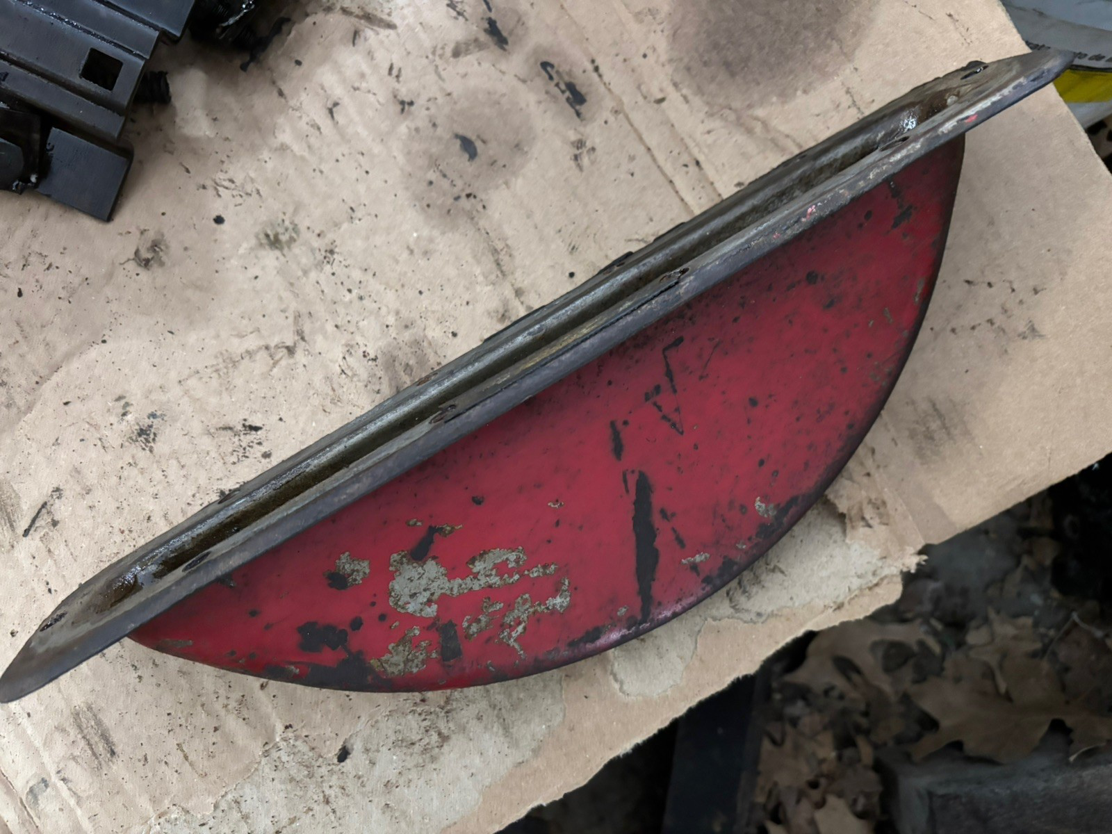
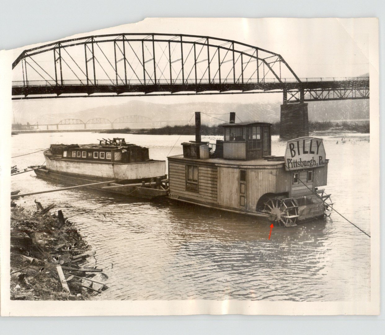
I'm continuing work on the hull. As I studied Billy's image the arrow points to an item I kept thinking looked familiar but I couldn't place it till this morning when I had one of those aha moments. It appears to be a tractor's rear axle gear oil pan. It makes sense that Engel would rig up something like that because he wouldn't have had access to oiling the outside shaft bearings. The inside shaft bearings were reachable from the engine compartment.

-
Your Albatros is looking awesome, James. Wonderful ratlines. They would look more complete if you could get up to the bottom of the cheeks but go as high as you feel comfortable with and don't worry about it.
-
Well, now that you put it that way......I guess I'll put a small window in each section facing forward. The door will be nothing fancy as it faces the foot of the stairs and opens inward. Thank you again, Eric.
-
Billy was definitely not chain driven, Tom. The engine sat between the wheels. Billy is quite quirky enough thank you very much.
-
I agree, Tom. This is why it's so dang hard for police to make sense of the various eyewitness accounts at the scene of a crime or so I'm told by NCIS. Thank you for the rendering, but where do the stairs land? I also think the pilothouse is centered, Keith. That's my story and I'm sticking with it. Speaking of sticking with it, after considerable conversations with myself I'm going with the center stairway. The one item item I can not argue away is the railing that runs parallel with the hull. I don't know why there are not two (one on each side) but I can't place that railing anywhere else other than for a center stairway. I'll just have accept the 6 x 10 foot sections on each side of the stairway as one of the many Engel idiosyncrasies. Thank you, Eric, Tom, and Bob for staying the course, sharing your thoughts, setting me straight, and forgiving (I hope) my hardheadedness.
-
I edited this after a respite with my pipe. You may have read pre edit. "Where I have the door marked doesn't work because you can't get around the stairs, duh. We have a similar door configuration in our house where access to the main stairway from the original kitchen has a door (the door is still there but is blocked on the other side of the door) with a step up to the main stairway. if it was a center stairway the door configuration could have been on either side at the bottom of the stairs." I'm not concerned about the pilothouse's structurally integrity, what I'm trying to say (badly I suppose) is the room below the boiler deck, on the main deck, would have 40 square feet removed from the center leaving little 6 x 10 foot sections on either side of the stairs. It's waste of space. To my eye it looks like it's in the center of the pilot house. *see Keith shrug The port side stack is much more straight than the starboard side, IMHO. I pointed out early on that they were decorative but that maybe the port side stack was functional for a wood stove. There is only 2 to 3 feet of space between the forward edge of the box that surrounds the stack and the forward boiler deck edge. If my thinking where correct the stairway opening on the starboard side would cut into the amount of surrounding box structure/ support for the starboard stack. Eric, my friend, I don't feel you're telling me what to do. You're sharing you thoughts on how you see things which is EXACTLY what I want you to do. Thank you for taking the time to make the drawing and for sharing your thoughts.
-
As much as I admire the desire to preserve that beautiful clock as original, I find it hard to believe that line is 300 years old and hasn't been replaced at some point. Did replacing the line make it non original? Not hardly.
-
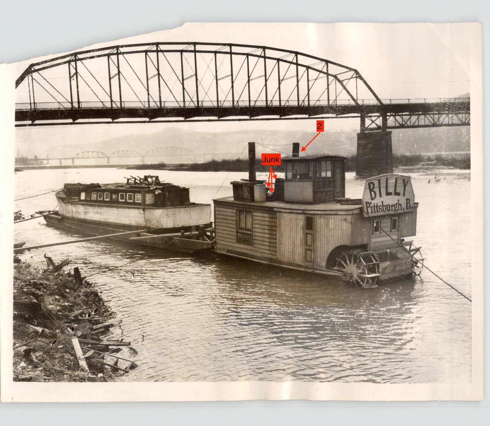
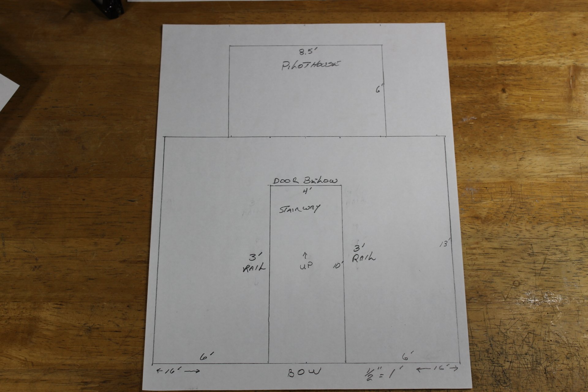
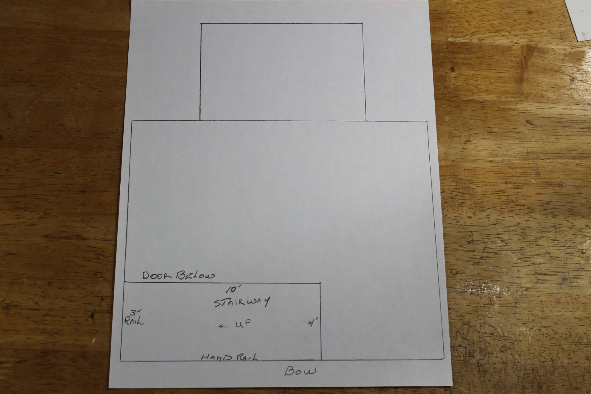
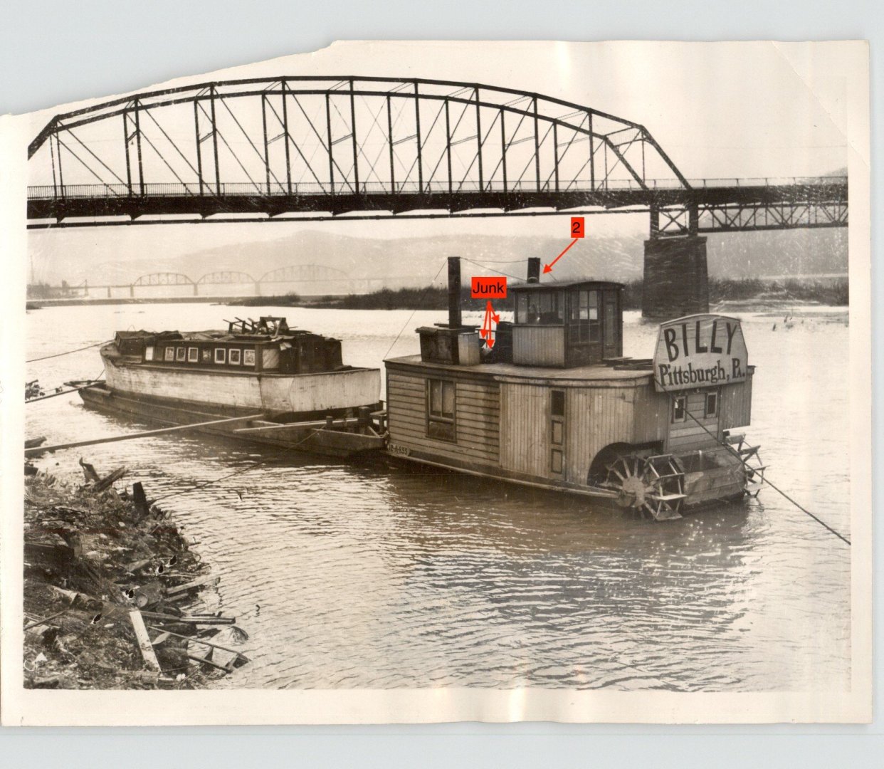
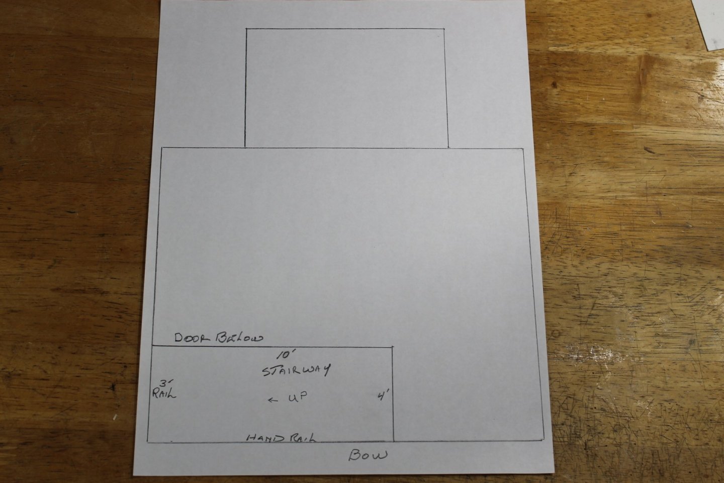
Eric, I hope the below drawings answer your questions. I believe so, Bob. Junk at the center of the pilothouse. I'll get to the stack below. Eric and Tom, is this the center stairway configuration you had in mind? If so it doesn't make sense to me because it cuts out so much of the deck structure below the pilothouse plus construction is much more complicated. Where I have the door marked doesn't work because you can't get around the stairs, duh. We have a similar door configuration in our house where access to the main stairway from the original kitchen has a door (the door is still there but is blocked on the other side of the door) with a step up to the main stairway. if it was a center stairway the door configuration could have been on either side at the bottom of th stairs. This is my thinking except the foot of the stairs are on the starboard side running up toward the center and the main deck structure door is on the 4 foot wall underneath the stairs. This allows more usable space in the main deck forward structure and construction is much easier. Regarding note 2 in the first photo, the reason the starboard stack leans is because the stairs being where they are don't allow the structural integrity as that for the port side stack. The only reason any of this matters is because it influences hull construction and deck planking layout. I can model it either way, I just need to know which way.

-
Tom, a door on the pilothouse fore wall leaves no place to put the ship's wheel. An inside stairway would mean it would have been open to the sky and elements and there wouldn't have been room in the pilothouse to have a stairway leading directly into the PH. As I noted in post #5, item 1, being a hand rail. The 'green' knee rail maybe a leftover piece of a salvaged porch rial leaned up against the PH? I'm not convinced it would have played a part in a stairway. I think the red handrail may sit along the starboard side roof edge? Creating the space necessary for a stairway at Billy's bow is a challenge that's way I favored a ladder until the question of how did Engel get heavy items up onto the boiler deck? There had to have been a stairway and a door, the how of it is the puzzle. When John enlarged the image I noticed that. If real, it appears to be a garden spigot with unknown reason for being. I know, I know, we are talking Billy here and reason seems at times sketchy. Due to the small size and not knowing the why of it I'm ignoring it and not including it in the build. Bob, if that's a stairway in front of the pilothouse it's completely plugged with junk and useless. Plus a center located stairway cuts into the center of the main deck structure below the PH. A stairway and door fitted into the removed corner on the bow/starboard side is making the most sense to me at this point. Tom and Bob, thank you for your thoughts and input.
-
Goober and Pile, Mississippi River whisky runners. You better be careful, Bob. Authorities are gonna arrest those two and confiscate your boat,
- 87 replies
-
- 3
-

-
- King of the Mississippi
- Artesania Latina
- (and 2 more)
-
The horn or lack thereof is the least of my problems right this second, Tom. The photo doesn't show access from the main deck to the boiler deck. There had to have been a ladder or stairs to get between the two decks. Because there was no walkway around the main deck structures, how did one access the main deck structures? I'm thinking there had to be a ladder or stairs along with a door on Billy's starboard side bow. I've been sitting here looking at the photo trying to think what that configuration looked like. I can't proceed with the hull till I have those bow details worked out.
-
Brian, the Choctaw would make an impressive model but I must say, I'm partial to the transitional period of 1850 to 1900 and either the Alabama or Harriet Lane would be neat builds. Whichever you choose I look forward to following along as your builds are a treat.
-
Sternwheeler, Brian?
-
The Caroline looks so impressive, Brian. Just an amazing build with fantastic attention to detail, the realism of the tarp is absolutely stunning.
-
That's a possibility, Tom. I'd have to mount it on the starboard side as there's nothing in the photo that supports a horn. We'll have to hold tight till the build gets further along. Thank you for the suggestion.
-
There's yard work and then there's yard work. Great progress. Bob. 👍
- 261 replies
-
- 5
-

-

-
- Victory Models
- Pegasus
- (and 3 more)
-
Thank you very much, Geordie. Tom and Tom, I've never added a tongue in cheek item to a model out of respect to MSW. In this case, even if I wanted to, scale would be the killer. A 6 to 9 inch bicycle horn to scale would be 0.050 to 0.075 inches in length. It would be so tiny one couldn't make out the detail in normal viewing regardless of how exacting it was made. Sometimes you have to take what Mr Keith says with a grain of salt.
-
Thank you, Keith. I placed ole Bob on administrative leave when the 3-D printed crew showed up. Instead of making him retire I put him in charge of spares. I wish you had been able to be here earlier and had brought up ole Bob. I would have sealed him inside Billy's pilothouse and let ole Bob float the Mississippi ever after. If I get to the mystery sternwheeler I may put an apron round his waist and place I'm in the galley. Yes, you missed the Susquehanna build in which I had a few moments of glory. John, Billy doesn't appear ready to weigh anchor. Maybe nav lights and a horn were items still not crossed off Engel's 'to do' list? I don't see any indication of electricity, very few of Billy's secrets are open to the viewer. Most have to be gleaned by deduction and speculation.
-
I'm thrilled, thrilled I tell ya to have you back and working on Cangarda, Keith. MSW wasn't quite the same without you.