Keith Black
-
Posts
6,759 -
Joined
-
Last visited
Content Type
Profiles
Forums
Gallery
Events
Everything posted by Keith Black
-

Length of boomkins on Pegasus?
Keith Black replied to Knocklouder's topic in Masting, rigging and sails
You're more than welcome, Bob. Glad I was able to help. -
Length of boomkins on Pegasus?
Keith Black replied to Knocklouder's topic in Masting, rigging and sails
Though a specific length isn't given in the below links, historically the length was six to eight feet on ships of that time period. You should be able to get a pretty good guesstimate from the images. Post #228. https://lehmanshipyard.com/2022/04/12/boomkins/ -
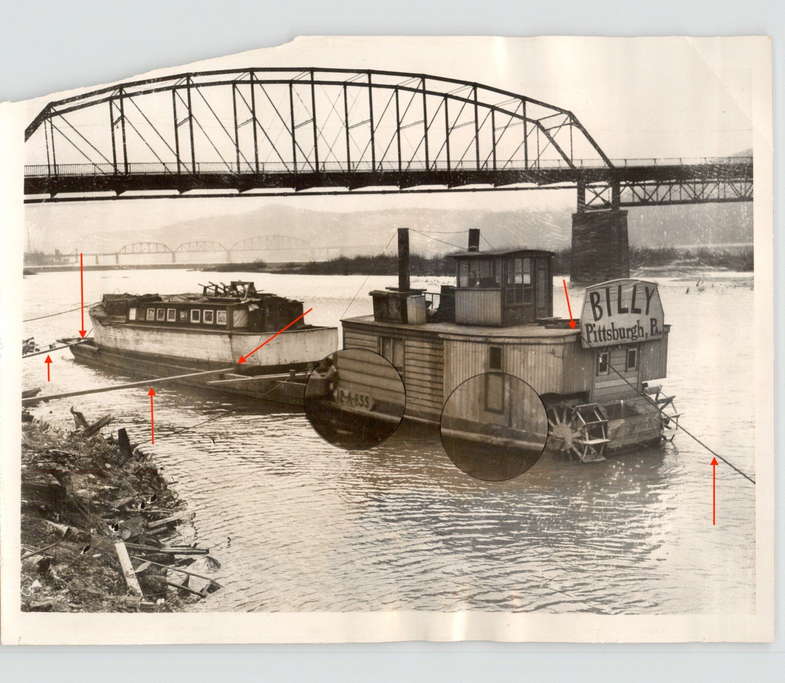
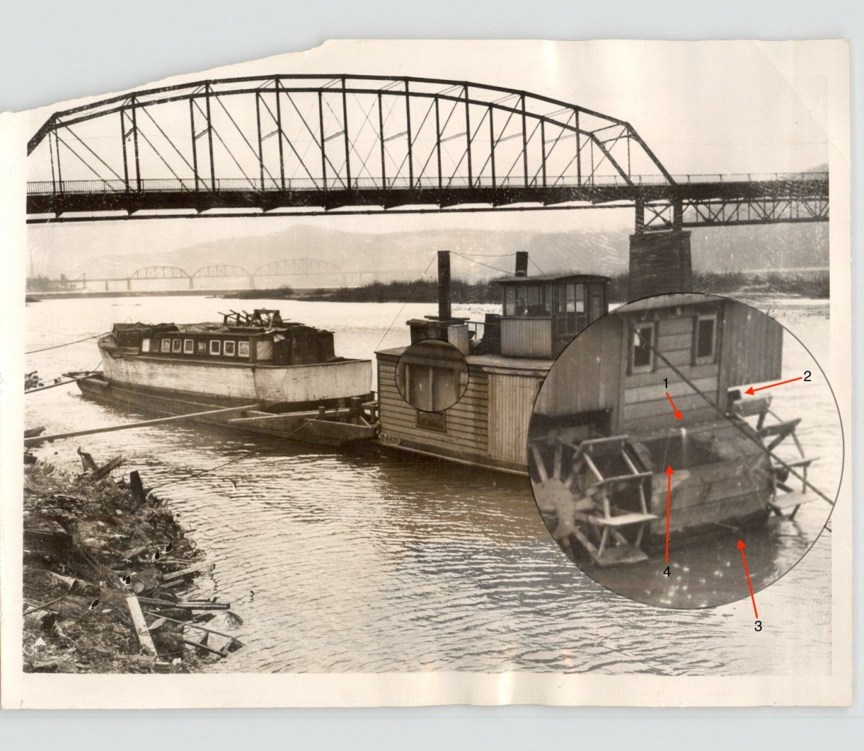
Roel, the stacks are not boiler stacks as there is no boiler though the port side stack might have been functional for a parlor stove? Being this is in the Mississippi, I think the barge and Billy were aground in the shallows. As far as the door goes, maybe? I'm still trying to get inside Engel's head. 1. Whatever that is, it's too small to be an exhaust. It almost looks like water running into the opening that's above the engine. 2. I'm very confident that is the exhaust. 3. I think that was the oil drain pipe? 4. That opening, was it roughed out with a sledgehammer and then artfully trimmed with a blowtorch? It's strange but then strange was Billy's middle name.
- 396 replies
-
- 7
-

-
- Billy
- sternwheeler
- (and 1 more)
-
Regarding Billy's main deck space, there's maybe a foot here on the port side and I assume it's the same on the starboard side. Also, Billy has about a foot of freeboard. All the springboards land on the barge as there isn't any deck space on Billy. That crazy door must have been strictly for ventilation. The stern line had to run from the boiler deck. If one came aboard via the barge, was there a door at the bow? There isn't a skiff in the photo, I have no clue how Engel planned on performing any repairs if required to outside walls of the main deck structure or the wheels?

- 396 replies
-
- 6
-
-
- Billy
- sternwheeler
- (and 1 more)
-
I am constantly amazed how your modeling skills have improved in four and a half years, Bob. You're taking on complicated task with ease and making a nice job of it. The Peg is looking really really spiffy. 👏
- 261 replies
-
- 3
-
-

-
- Victory Models
- Pegasus
- (and 3 more)
-
Ron, thank you joining in the journey and thank you for the suggestion. Two over one windows in 1930's were 24 to 48 inches wide by 36 to 72 inches tall. I think the window is 72 inches tall, width is yet to be determined.
- 396 replies
-
- 6
-
-
- Billy
- sternwheeler
- (and 1 more)
-
I received Billy's original press photo with the writeup glued on the back. Obviously the image is more crisp which may help determine colors. I plan on having it framed and placed/hung near to where Billy will be displayed.
- 396 replies
-
- 7
-
-
- Billy
- sternwheeler
- (and 1 more)
-
Thank you for following along, Steve. As for as the colors for Billy, lots of dirty white! Nooo, not all will be dirty white, that goofy door is tan with unknown trim color (red, maybe?) and the large window may also be tan. That vertically sided addition at the bow might be a dirty yellow? Possibly some stained wood around the window at the rear of the pilothouse and black paint where needed. Billy may have been ugly but when modeled he might turn out to be a bit colorful.
- 396 replies
-
- 5
-
-
- Billy
- sternwheeler
- (and 1 more)
-
That would make for a challenging build but the story is worth the telling, Paul. 👍
- 396 replies
-
- 3
-
-
- Billy
- sternwheeler
- (and 1 more)
-
This is such an amazing build, Matthias. Truly inspirational.
-
The Peg is looking fantastic, Bob. Congratulations on getting all the ratlines tied. 👍
- 261 replies
-
- 3
-
-
-
- Victory Models
- Pegasus
- (and 3 more)
-
She's a beauty, John. Great looking wheel. 👍
-
Welcome to MSW. Sternwheelers have almost zero rigging. Glad to have you aboard.
-
I love British canal boating. I'm subscribed to Cruising the Cut, it's one of my favs and David John is a hoot. Had I life to live over I would have emigrated to England long ago and found out what living is like aboard a narrow boat.
- 396 replies
-
- 6
-
-
- Billy
- sternwheeler
- (and 1 more)
-
In doing research on canal boats for images that might suggest Engel's cruiser was a converted canal boat I came across this canal boat image. Looks pretty similar. The Erie Canal was an important part of American history yet very little of that history has been explored here in MSW. Hopefully someone becomes interested in that wonderful history and wants to model the great workboat subjects that ooze from the muddy banks of the Great Cut. I'd be that Huckleberry except my remaining time is too limited for an already full picnic basket. https://www.eriecanal.org/boats-2.html I think I'm going to model just Billy and not the barge and cruiser. I know that's telling just half the story but half the story is all that I'm really interested in and have time for.

- 396 replies
-
- 12
-
-
- Billy
- sternwheeler
- (and 1 more)
-
Hello from the banks of the Tyne
Keith Black replied to Geordie Tyne's topic in New member Introductions
Geordie, welcome to MSW. Good looking builds, glad to have you aboard. -
Lynn, golf season is over. Time to get back to work on the Phantom.
-
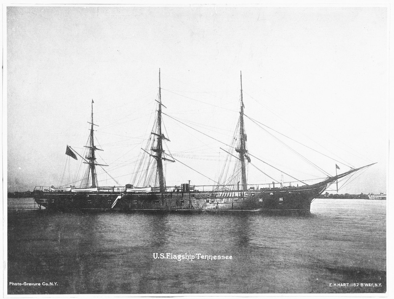
Thank you, Phil. Never in Fulton's wildest nightmare would Billy have appeared.
- 396 replies
-
- 6
-

-
-
- Billy
- sternwheeler
- (and 1 more)
-
Maybe, Bob. I thought it kinda looked like monkey rudders but I'm not sure. For me it's just one of the many curiosities I have in my collection of ugly sternwheelers. Oh my, Harvey.
- 396 replies
-
- 6
-
-
-
- Billy
- sternwheeler
- (and 1 more)
-
Ken, I think Engel bought a couple of buildings and a chicken coop and cobbled them together on the main deck. Kind of a sternwheeler crazy quilt. The car ferry is just one of my many photos of ugly sternwheelers that was the closest one to grab and attach in answering John. It's not one I envision building but yes, what is going on with the wheels? It's gas powered but there are some extra large pieces at the stern of the wheels I'm unfamiliar with.
- 396 replies
-
- 4
-
-
- Billy
- sternwheeler
- (and 1 more)