DONATION DRIVE - SUPPORT MSW - DO YOUR PART TO KEEP THIS GREAT FORUM GOING!
×
Keith Black
-
Posts
6,667 -
Joined
-
Last visited
Content Type
Profiles
Forums
Gallery
Events
Everything posted by Keith Black
-
Glad to have you back with us, Don.
-
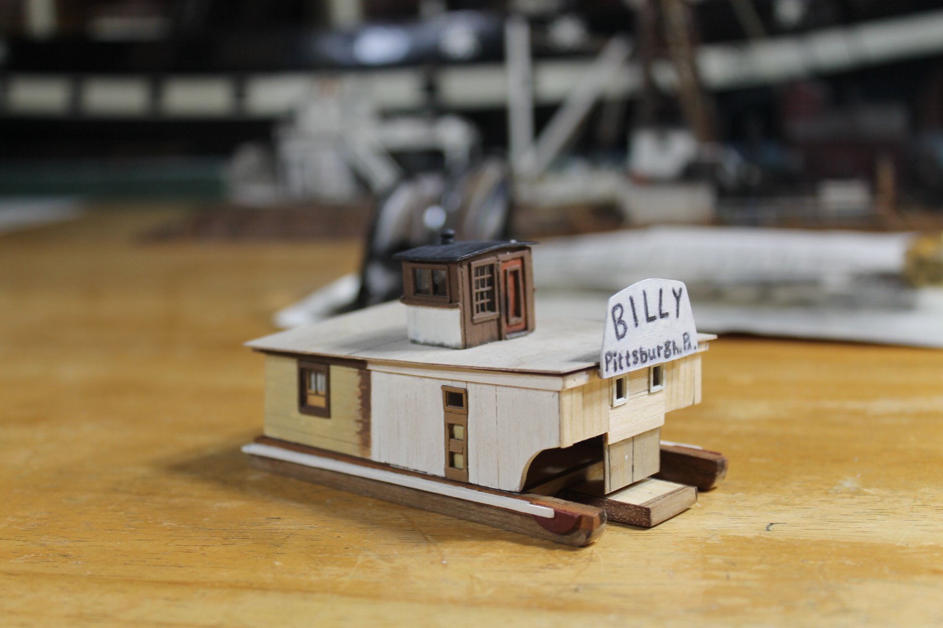
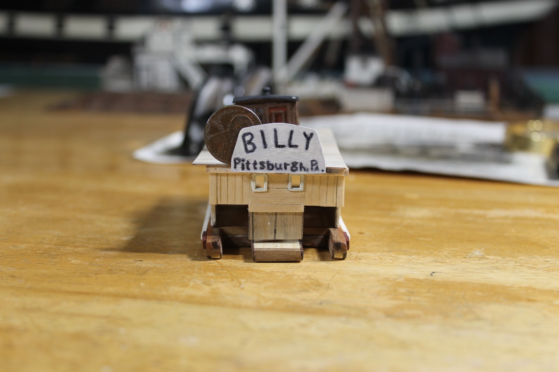
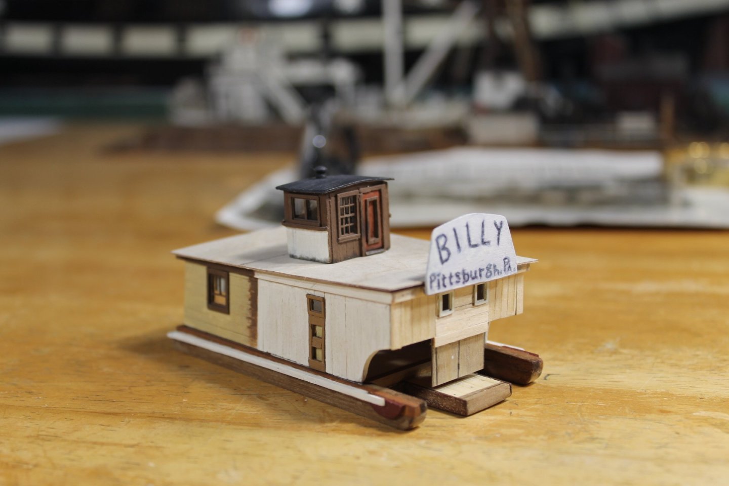
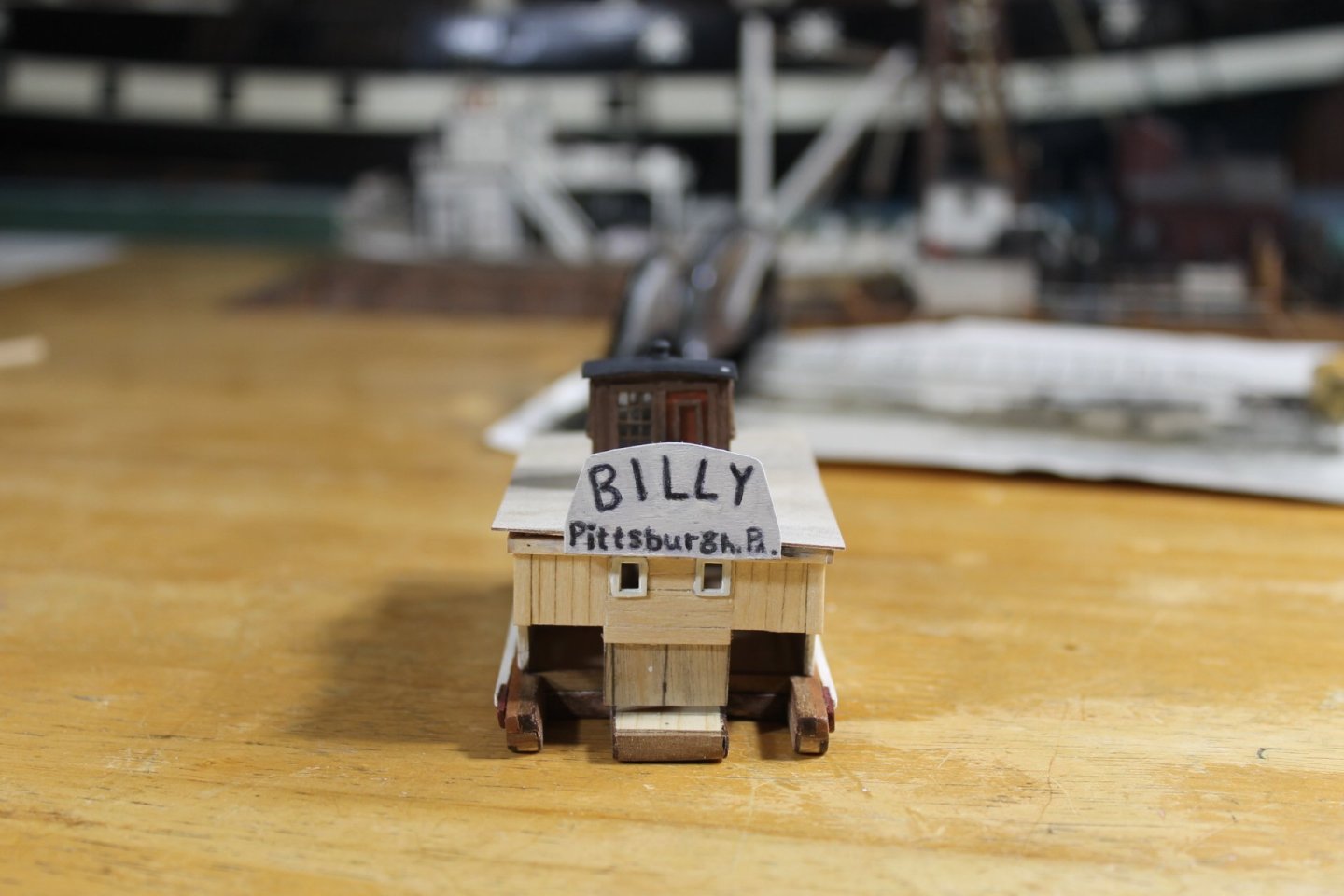
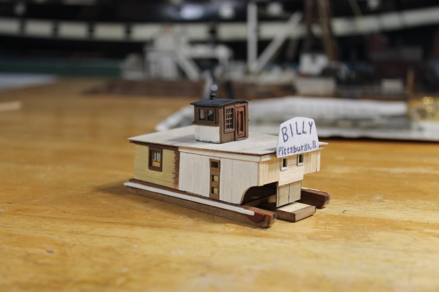
 Thank you to everyone for the likes, for your helpful suggestions, and for your patience during the name board discussions. Name board 1.0 Name board 2.0. Lettering was washed with heavy watered down white paint. And finally name board 3.0. The letters are hand painted with acrylic craft paint. I know there are thousands upon thousands upon thousands of folks that can do ten times better than I on this lettering on the name board but this is the best I can do. I'm done trying to do any better, I'm calling it done with 3.0, no mas. Please believe me when I say this looks a lot better at normal viewing distance than in a close up photo. The penny for size comparison. Most of the lower case letters are 0.10" high, some a bit smaller. Enough procrastination, on to the arches. Again, thank you for your patience, your support, and for being part of the journey Keith


-
Thank you for posting, Julie. I always enjoy your post. Eric, I think it's painted canvas stretched over board but I could be wrong. I've been wrong so many times lately I've lost count. I can't imagine trying to hand letter on silk span, Tom. Nicely magnified image. That proud wooden border is what I think are tack strips, Tom. Thank you for the suggestion, Harvey.
-
Congratulations, Bob. Your Pegasus build is your best so far. I look forward to your next journey.
- 261 replies
-
- 4
-

-

-
- Victory Models
- Pegasus
- (and 3 more)
-
Glad to see you've pulled up a chair, Kurt. Your vast experience and input is very much appreciated. After viewing countless times under heavy magnification I'm certain that the lettering was done on canvas, you can see the tack strips on the edges of the name board. Thank you for the idea, Tom but i'm going freehand lettering and let the devil take the hindquarter.
-
Thank you, Paul. Yes, the L's need to be heavier at the bottom. Thank you for the sage advice, John. I went to a serif font generator and Pittsburgh, Pa. is different than the lettering on Billy's name board. The ending "a" in the abbreviation Pa. is a lower case "a" not a small capital "A" https://www.namecheap.com/visual/font-generator/sans-serif/ Yes, the lettering was painted on canvas and badly stretched over horizontally run boards. Absolutely, Phil. What is the goal? If I use printed letters it's not going to look like the letters on the name board I don't care if the "a" was the same because the lettering will look manufactured, not hand painted. Right now I'm close. The letters need to be darker and some adjustments made as Paul suggested. I am not going to use the dry transfer letters I have coming, they'll go in my stash. Once the name board is done it needs to be able to have acrylic paint applied and not be adversely affected. The goal, IMHO, is to not only try and build as close to an exact replication as possible but to also capture the spirit of the subject. I think that lettering done by hand will far better capture the spirit of the name board than printed lettering, IMHO. The trick is, for me being one who is lettering impaired, to be able to make the lettering acceptable. A little secret, sad as it is, this is the best copying of lettering I've ever done. In the end of this project I'd like to be able to say, "yeah, I did that lettering myself" Please forgive this little distraction as I'm stalling building the arches. I keep running the best options through my three cell computer before committing to a course of action.
-
Thank you, Tom. It's just not 'there' yet, you know what I mean.

-
John, thank you for the idea, Bob @Knocklouder suggested the very same earlier. Depending how this looks when I cry uncle I may give the printing idea a shot.
-
Congratulations on completing your first build and doing such a swell job of it, James. I know you Dad is looking down with pride and a smile.
-
Thank you, Eberhard.
-
Siggi, my eyes only see beauty and I'm sorry to hear you're not satisfied but I completely understand. The builder's satisfaction is the only thing that matters when building our models.
-
The name board height has been corrected. I tried doing the lettering freehand, I've gotten close but not there yet. Keith

-
Thank you for the idea, Ron.
-
If that doesn't look real I'll kiss your cat.

-
Paul, welcome to MSW. Wishing you great success with your Polaris build, glad to have you aboard.
-
Simply unbelievable.
-
No problem, Eric. How very kind of you for the offer, Eric. I may not do the barge and canal boat and if I do the signs would need to be close to the window sizes. Should I decide to build the barge I'll revisit this with you in a PM. Thank you again.
-
I have a sheet in route from Woodland Scenics that I ordered yesterday, Eric. As I mentioned to Bob, they're not exact but they'll be hundreds of times better than what I could do by hand. As far as the windows go, you're correct, Eric. The windows could be treated any number of different ways and we'll leave it at that. Thank you, Eberhard, Eric, Bob, and Geordie for you input.
-
Great googly moogly, Bob. You and bowsprits are like a divorce attorney and weddings.
- 261 replies
-
- 7
-

-
-
- Victory Models
- Pegasus
- (and 3 more)
-
I've never printed my own, have thought about it but never attempted it, Eberhard. Geordie, I think every junkyard in Pittsburgh was Engel's oyster.
-
I've got some letter transfers coming that will work but they aren't exact, Bob. i've never done the mod-lodge thing so I'm a bit leery about trying to learn a new skill though that's a bit lame.
-
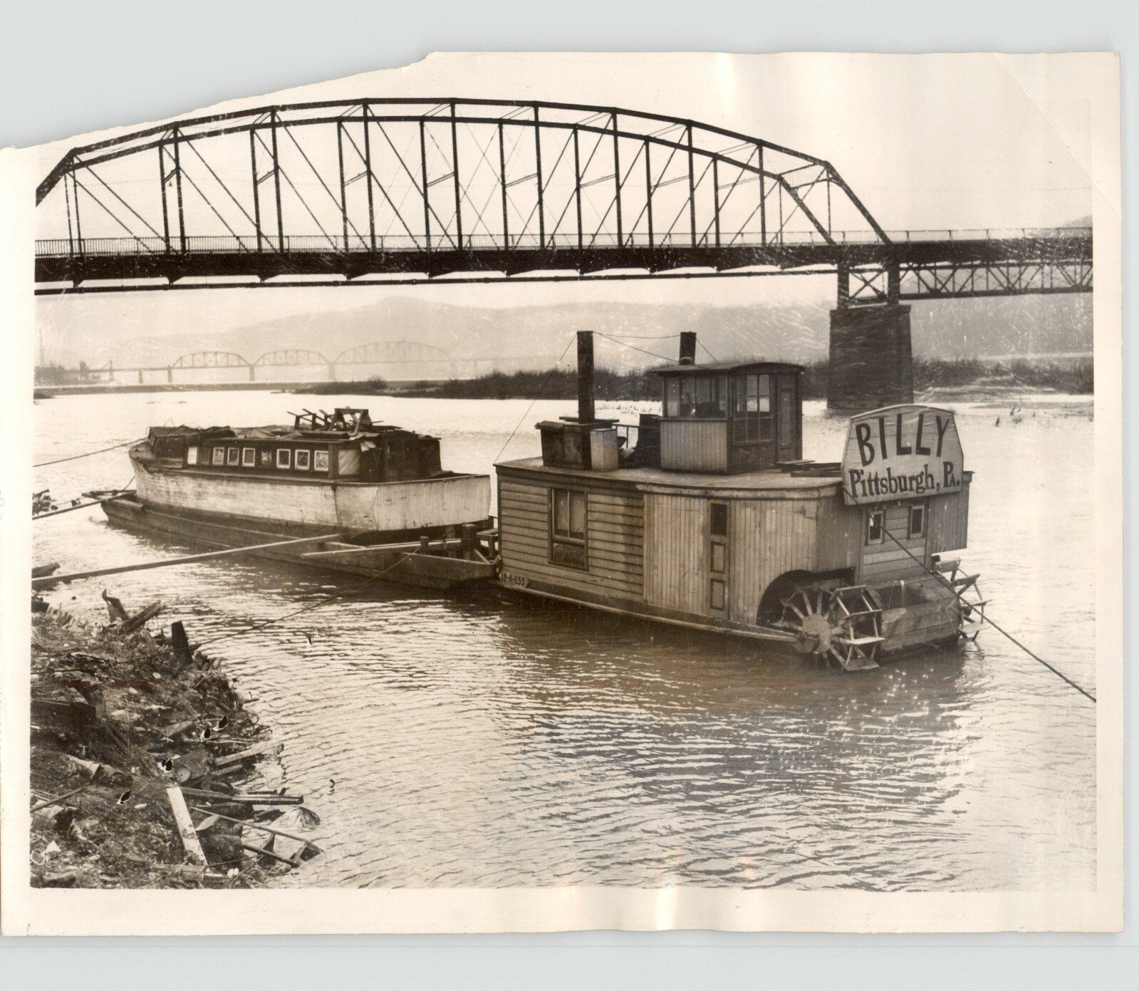
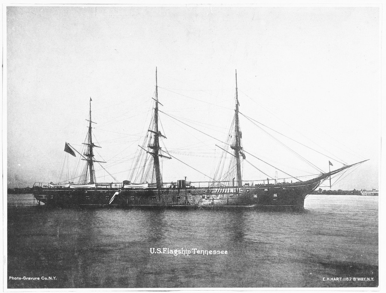
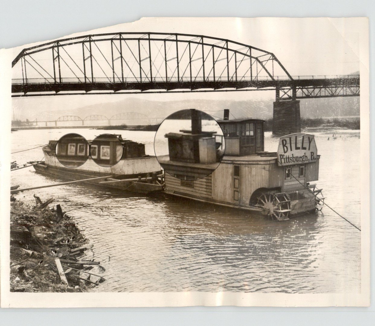
The type of signs is unimportant, it's, are they signs? Yes they are, Eric. But going back to the press wright up, Engel's boat had been damaged in a flood and Billy was his ticket to getting the boat down south to make repairs. It looks to me like they are signs put in as temporary replacements for damaged windows. I think ole Engel was a scavenger so putting in signs as a temporary fix seems plausible. They don't look like like curtains to me, Eberhard? They could be but the window shades in Billy's windows are plain Jane.
-
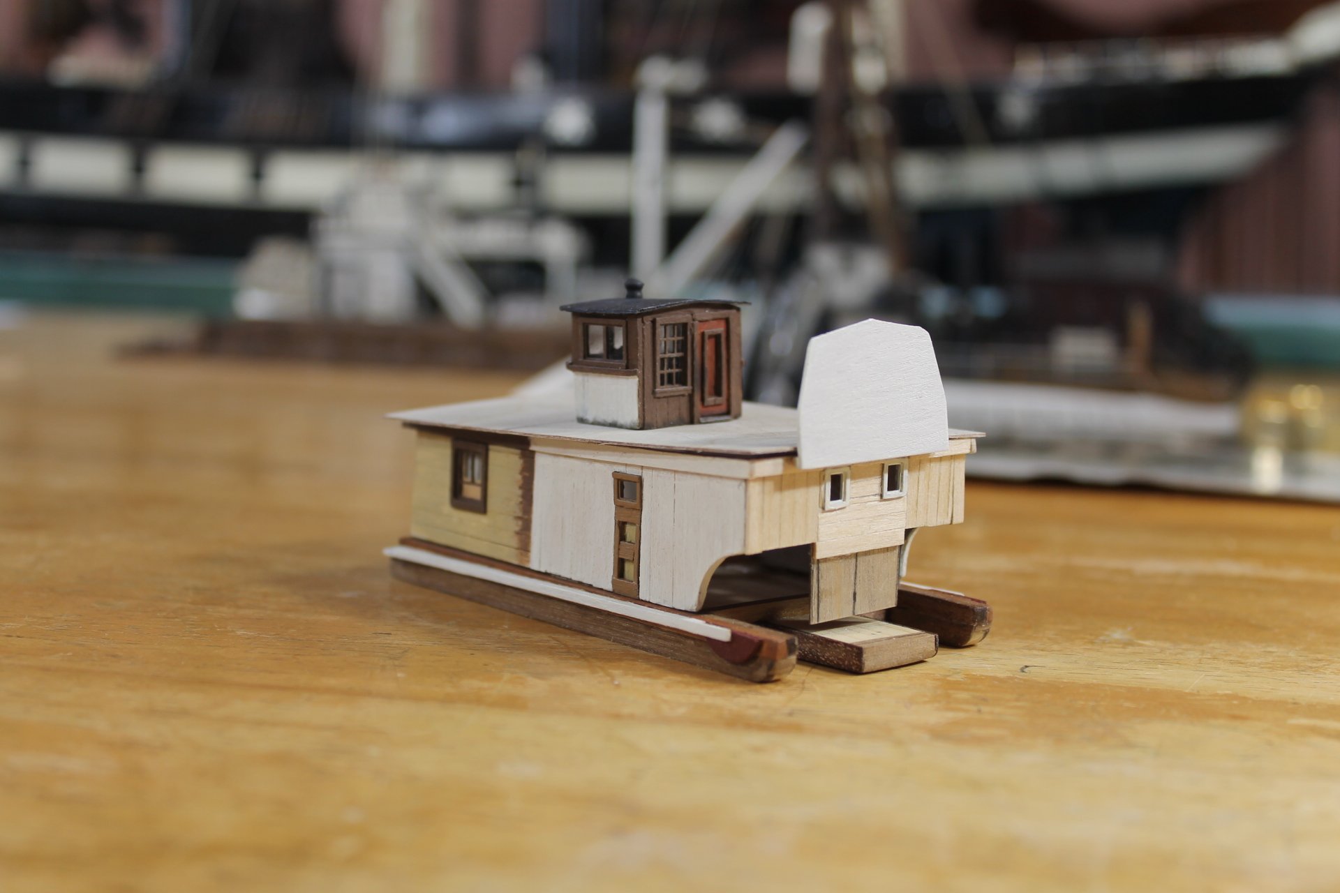
Thanks to everyone for the likes and comments. The stern is starting to take shape. I set the windows about 0.05" too high but I'll have to live with it. Billy's name board's width is okay but the height needs to be lowered about two feet. It's easily removable and made so as i'll need to remove it to add the lettering. I'm a pretty good painter but I can't do lettering for beans. Attach, remove rinse and repeat is all part of the process on the stern as it is so complicated. Question....... in the enlarged loops, are those heavy cardboard or porcelain signs? I"m not going to try and replicate them, it's just a question to satisfy my curiosity. Thank you. Thank you to all for being part of the journey. Keith

-
It's good to see you back working on the Cecilie, John. Are you still working in view of museum visitors?
-
Eli, welcome to MSW. Nice job on the Endurance, glad to have you aboard.