


el cid
-
Posts
143 -
Joined
-
Last visited
Content Type
Profiles
Forums
Gallery
Events
Everything posted by el cid
-
I still wonder if both cables weren’t left turned on the drum. Even with the pawl engaged, an anchor could be lowered by letting the line slip around the drum in a controlled manner. To me this would be a much safer method for dropping anchor than just cutting it loose to run out wildly. And if turns weren’t on the drum before anchoring, when weighing anchor the crew would have to haul up all of cable from below (and I suspect the bitter end was secured to a hard point in the hold), and thread the end of the cable around the drum several times and then feed all the excess cable back down below. If anchored in shallow water, that could be a lot of excess cable. FWIW, Keith
-
Hmmm, good one. Perhaps both cables had turns on the winch but the turns for the one not being worked were left slack or loose around the winch barrel. A winch or windlass will only take a strain when there is tension on the inboard end of the line, otherwise the line will slip. Having turns around the winch or some some other hard point would also help the crew control the anchor as it’s dropped and the ship backed down to set the anchor. Having handled my fair share of mooring lines, it wouldn’t be fun hauling all the line out of the cable tier to get to the bitter end so as to get it off the winch, but maybe that’s what they did. HTH, Keith
-
My guess would be that after the first anchor is set, the cable was “stoppered,” taken off the winch, then turned around an appropriate hard point (eg. riding bitt). Then the cable for the second anchor was taken to the winch and the process repeated. Curious to learn if there was another method. Cheers, Keith
-
I really like the added bolt detail, as you say, they’re pretty prominent on the prototype. Not to derail Jon’s log, but does anyone know if these would be a common construction feature on other vessels of the period (eg. the US Brig Syren)? Any references to recommend re: this shipbuilding practice? Thanks ahead, Keith
-
Have you seen these resin dry transfer rivets? I haven't used them myself, but might save considerable time. https://www.archertransfers.com/PAGE_Rivetpic.html Cheers, Keith
-
US Brig Syren by Gahm - Model Shipways
el cid replied to Gahm's topic in - Kit build logs for subjects built from 1801 - 1850
Yeah, I know what you mean. The bar has been set pretty high. Still fun to learn new techniques from the masters here and attempt to emulate. -
"When I opened the box I found a jumble of sticks. They were not separated or packed by size." LOL...I have a faint recollection of a Mad Magazine (or similar) cartoon of a kid opening a model kit and finding the same. And funny you mention Ben Franklin, a favorite five and dime when I was growing up in Northern Virginia. Was telling my wife about it the other day (she from Texas had never heard of it). Hadn't thought of that store for years and actually believed it long defunct. Looking forward to following your build. Cheers, Keith
- 82 replies
-
- 2
-

-
- skipjack
- wye river models
- (and 2 more)
-
So my understanding is that in early designs, those “decks” where the gratings are located were simply walkways connecting a raised f’ocsle and quarter deck. They evolved to form a more traditional deck except for the open waist. So perhaps these walkways (and the fore and aft decks at the same level) aren’t considered the main deck, with hatchways to the ship’s interior. Perhaps the main deck, for purposes of watertight integrity (such as it was), was the deck on which the boats are stowed. Therefore there would be no need to make the gratings watertight (ie raised comings to secure a cover). As to the purpose of the gratings, I’d guess they were intended to help dissipate smoke from the guns and let in some additional light. Cheers, Keith
-
Re: Jud's astute observation. I think the modeler should consider whether they are representing the ship as a clean, prototype display (clean, no weathering, no paint fading, no rust, grease, etc) or as an "in service" display (weathered, worn, and faded, rust streaks, grease stains, etc). Well cared-for museum ships like Victory are more like the former; an active ship, even a well-kept ship, is going to show signs of wear-and-tear. The pitfall for modelers is inadvertently mixing the two representations. FWIW, Keith
-
Tung Oil "Experiment"
el cid replied to knightyo's topic in Painting, finishing and weathering products and techniques
My observations re: pure ting oil, not tung oil “finish,” on new walnut rifle stocks. First couple of coats cut 50:50 with mineral spirits. Applied liberally and allowed to soak in for about 20 minutes or so, then excess buffed off. Wait about a day between applications. Later coats, maybe 10 or more for long-term protection, cut about 75:25 tung to mineral spirits. Buff well with a cotton tee shirt in between.applications. Makes for a nice deep, water proof (or resistant) finish. Note that with age the tung oil oxidizes to a nice reddish brown color. Not sure this directly addresses your post, but maybe cutting the tung more will help even out the splotches. HTH, Keith -
I suspect that because the upper sails and yards were relatively small, it was easier and perhaps safer to furl these sails by lowering the yards (as opposed to rigging and stepping out on foot ropes and pulling the sails up). During heavy weather the upper yards (with sails attached) and masts would be struck down to the deck to lower the ships center of gravity and reduce windage aloft...I think this was a common evolution for ship's crew. HTH Keith
-
If you’re doing a seascape display, you might want to check out the technique described here: http://www.shipmodels.info/mws_forum/viewtopic.php?f=4&t=155661 I believe the modeler is a professional artist and his painting, weathering, and seascapes are perhaps the best I’ve seen. Unfortunately I think he’s moved on from ship modeling, but am greatful he was kind enough to share his techniques. HTH, Keith
-
While I'm unsure during what condition the guns would be kept loaded...always when underway or only when enemy action was likely or expected, I doubt they were loaded and unloaded daily. It was though probably common, at least in well-run warships, to exercise the guns regularly. Probably have the gun crews go through all the motions except for actually loading and firing (to conserve powder and shot). I can't cite a reference nor do I have direct experience with muzzle-loaded artillery, but I suspect once the guns were actually loaded, they normally stayed in that condition until fired (with a tampion in the muzzle to keep moisture out). I'm sure there were tools for removing the wadding, shot, and powder in case of a misfire, but this operation was (is) probably inherently dangerous. Hopefully someone else here has a good reference and can give a more accurate answer. HTH, Keith
-
I usually try to get the major components assembled and prepped before beginning to prime and paint. I haven't built a plastic sailing ship since I was a little kid (Revel Flying Cloud I think), but for modern ships I'll build the hull and add the deck so I can get good clean joints all around. I'll also assemble the various superstructure components and clean them up too. If there's a joint that will need to be cleaned, I'll attach superstructure pieces to the hull before painting everthing together, otherwise I paint the hull and superstructure pieces separately then assemble. I picked up a trick somewhere along the line whereby you spray your deck color first, then by spraying the hull and superstructure at a low angel (i.e. from below the deck level), you don't need to mask the decks. Just some touch up with a brush where there is slight overspray or paint "holidays." Very important...where you do paint parts before attaching, you have to scrape or sand the paint off of each surface where the parts meet. Remember, styrene cement (e.g. Testors liquid) is a solvent that "melts" the plastic parts together. Paint effectively prevents the chemical reaction from occurring. You're on the right track, thinking ahead and problem solving. Cheers, Keith
- 49 replies
-
- 2
-
-
- constitution
- revell
- (and 1 more)
-
Cement together, fix gap and any other flaws, prime and paint. I also tend to attach any other sub assemblies to the hull before painting, if feasible. HTH, Keith
- 49 replies
-
- 3
-
-
- constitution
- revell
- (and 1 more)
-
Bob, it looks like we were typing at the same time. I was trying to make similar points, but your response is articulated much better than mine. Cheers, Keith
-
Couple of points re: "definitive" sources of info on rigging, especially running rigging. Unless there is photographic or other evidence for a specific vessel at a specific point in time (e.g. "as built"), all we can do is make reasonable, educated guesses as to the exact configuration. Often there are many different ways to perform a particular rigging task, and I suspect period sailors had their favorites (that were perhaps not well documented in the literature). Therefore rigging configurations may have changed with a vessel's captain, sailing master, or bosun, or just evolved over time. Also, maybe rigs varied based on materials and supplies (e.g. blocks, line of a particular size, etc) available at a particular point in time. I offer the example of main sheet controls for a modern recreational sailboat (see https://www.harken.com/content.aspx?id=3901). All are "correct" and will serve the purpose, but pick a popular boat model that's been around for any length of time and I'll bet you can find a variety of different main sheet configurations, modified per each owner's preference. For modeling, I use the available resources to help understand the purpose of a particular rigging system and then try to think like a sailor when deciding on which technique makes the most sense (considering of course general time period and nationality). FWIW, Keith
-
For joining styrene to styrene, I always use a liquid solvent like Testors. With the model parts joined together, you can use a small pointed brush or a pipette to apply the solvent to the joint. Capillary action will wick the solvent into the joint and effectively “melt” the parts together quite neatly. I typically use CA for attaching resin or photo etched parts. Thin CA will wick into joints neatly too. White glue can also be used for attaching photo etched parts, especially small-scale ship’s railings and such. And for gap gap filling I haven’t found anything better than Bondo Spot and Glazing putty. My oldest surviving models are 20+ years old and everything seems to be holding together. HTH, Keith
-
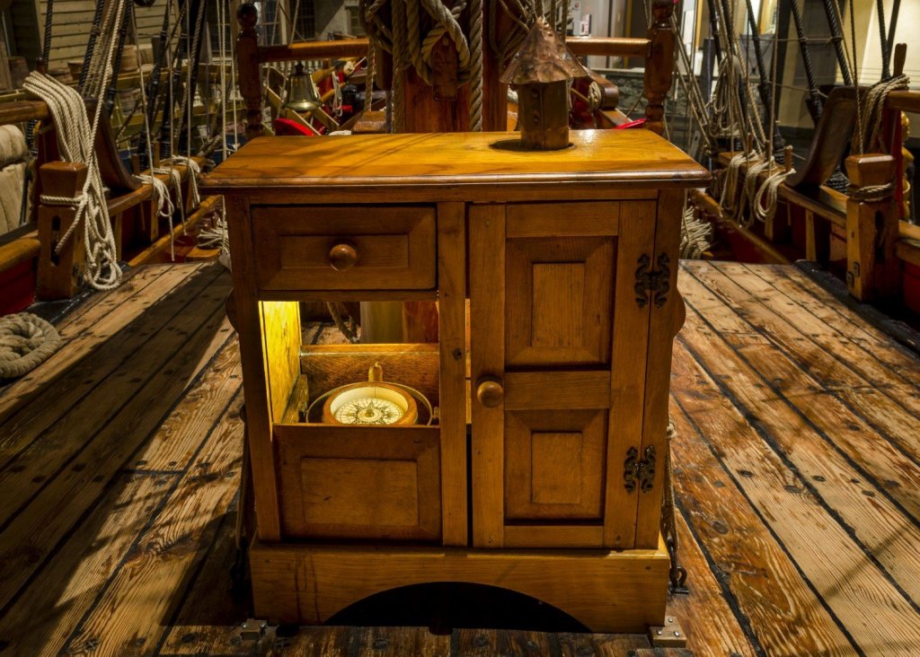
There seems to be a dearth of information on binnacle cabinets. This is a replica of a 17th century cabinet from the vessel Nonsuch (found at the Manitoba Museum website).
-
All encompassing compass considerations
el cid replied to JerseyCity Frankie's topic in Modeling tools and Workshop Equipment
There’s a reason compass leads are used in drafting, as opposed to just chucking a pencil on one leg. Compass leads aren’t sharpened to a conical point like a pencil, they’re sharpened to a bevel. That way as the lead dulls, the diameter of the circle (or arc) doesn’t decrease too (as measured at the inner edge of the line). Hard to picture in the mind’s eye, but I suspect if one could find an old drafting textbook, this would be better explained and illustrated. Cheers all, Keith -
I agree, these are interesting little ships and I'll be following your build. With patience nearly any plastic kit, even the older poorly fitting ones, can be turned into a gem. For joining styrene, I suggest using Testors liquid or similar solvent. With these you're not really gluing parts together, but melting them together. With parts that fit together well, you can hold them together and let capillary action draw the liquid solvent into the joint, usually makes for a very neat job. I haven't used tube glue since a teenager in the '70s but remember many messy glue joints (blobs and such). CA is useful for joining non-styrene items, as is plain old white Elmers, depending of the parts and expected stresses. Some use CA for gap filling (often w/ baking powder to thicken), but I haven't had much luck with it. Somebody turned me on to Bondo Spot and Glazing putty (available in a tube at most auto parts stores) and I never looked back. Dries quickly, sands easily and smoothly, and can be scribed if needed. It contains a solvent that acts on styrene too so it becomes "one" with the model. HTH. Cheers, Keith
-
A machinist turns a brass cannon barrel
el cid replied to Bob Blarney's topic in Modeling tools and Workshop Equipment
Lathe work is like magic. I've turned some decorative wood items (bowls, table tops, etc) but my only experience turning metal is doing brake rotors and drums. And even that process gave me great satisfaction (I'm easily amused). Thanks for sharing!- 1 reply
-
- 3
-
-
My first thought is that they’re hull “stiffeners” as sometimes added to longer ships, but I suspect a lightship would require support pretty often, so I’m guessing those structures are actually fenders to help prevent hull damage when vessels are alongside. Just a guess. HTH, Keith
-
I don't know a reference or specific knot, but will offer that when underway in open water where the anchor wouldn't be readied for use, it would be very well secured with multiple lashings to minimize any chance of the anchor shifting (at least that's how this seaman would do it). I also understand that for extended offshore sailing the anchor cables would be untied and stowed below and the hawse holes plugged. Depending on the layout of the ship and availability of suitable hardpoints (e.g timberheads, cleats, etc), I would think multiple turns of a line around the anchor and hardpoint then maybe finishing on the timberhead with a clove hitch or on itself with some half-hitches. HTH, Keith
- 1 reply
-
- 3
-
-
Jim, Perhaps my favorite sea story is Monsarrat's "The Cruel Sea" (and the associated stories compiled in "Three Corvettes"). Your North Atlantic convoy paintings really convey the atmosphere of the events he describes. Thanks again for sharing. Cheers, Keith

