RiverRat
-
Posts
206 -
Joined
-
Last visited
Content Type
Profiles
Forums
Gallery
Events
Everything posted by RiverRat
-
 Having seen your collection of carvings, I was going to point out this post to you..........too late! Bob (hexnut), What tools did you use to do your carving? Brian
 -
Hello Ferit, I just have to keep coming back to check on your log! It's such an elegant ship to begin with, and your excellent craftsmanship has been a joy to watch as it progresses. What beautiful work you're doing, especially replacing the kit parts with your own. Brian
-
Hey, nice looking model, and you did a great job overcoming the poor instructions provided! As far as being intimidated by others' skills....POPPYCOCK! Yes, there are quite a few awe-inspiring builds here, but there are even more who are rank novices, or nearly so, and with a log for your Rattlesnake (I have a current bias for this ship ) there is plenty of expert help if needed. Brian
-
Impresive! What operations will you actually have using R/C? I can't imagine controlling a large number of sails. Brian
-
You'll find that most ships have a "sheer", where the deck is lower in the middle compared with the fore and aft, a long sweeping curve, and a "camber", where the deck is higher in the middle than at the sides. Think banana. You'll need to clamp/pin/weight the false deck down to the bulkheads, providing they're correctly shaped from the factory (look at the plan's drawings) rather than shimming them up to the deck.
-
Very good! Thanks so much. But it looks like it has little travel side-to-side to be of much more advantage than an eyebolt? But then I know near nothing of handling a boom............... Brian
-
Thank you all for the insights. John, some of the Mamoli drawings that aren't of a "square" view are poorly done. The horse is about half the height of the rudder top and halfway back to the transom. Clearance is not likely an issue. Edit: Wayne. I just looked at a Hahn drawing too. Unclear also, but the side view of the lower attachment looks more horsey than ringy Brian
-
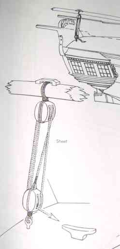
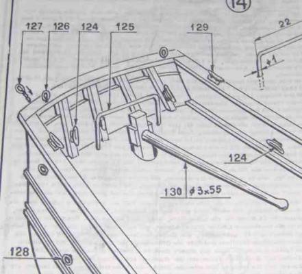
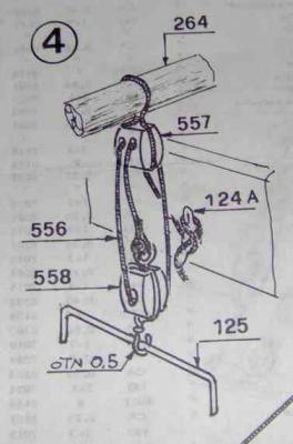
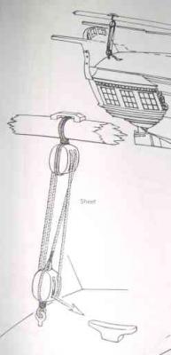
Looking far far ahead at some of the rigging instructions for my Rattlesnake privateer (I'm only at the first planking stage...), it has a "horse" (part # 125) for the mizzen boom sheet. #264 is the mizzen boom: On the model, this is bent brass wire. Anybody have an image or a description of how a horse actually looked? I don't know what the Model Shipways version does for this rigging. Lees in '...Masting and Rigging..." mentions the horse but suggests an eyebolt was generally used, such as this image from Petersson "Rigging Period Ship Models". I suspect using a horse versus the eyebolt was the model designer's choice and not necessarily the definitive arrangment. I'd likely go with the eyebolt version without a better vision of the looks of a "proper" horse. Thanks! Brian
-
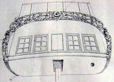
Hi Aaron, The Rattlesnake uses a tiller, no wheel, and the rudder post rises through the cabin up through the quarterdeck. It would block the use of a window in the middle, apparently. Here's a National Maritime Museum Admiralty drawing of the stern, showing the windowless space. Just a frame or moulding for appearance it seems. Other things to note: The solid lines inside the "ears" of the carving may indicate a space between the sides and the carving rather than solid like in the kit models. See Pasi Ahopelto's scratch-build Rattlesnake here at MSW for example. I believe the dark circle on the lower right might be the exit for the captain's "seat of ease" Brian
-
Hi Zev, Welcome to the Rattlesnake community! I'm doing the Mamoli version so I may not have much input into the MS version particulars, (the Italian to English translation of the instructions sometimes really sux!), but will keep an eye on 'ya. Be patient, have fun with it, ask for help here if needed. Enjoy the challenge and the process. Regards, Brian
-
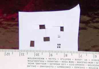
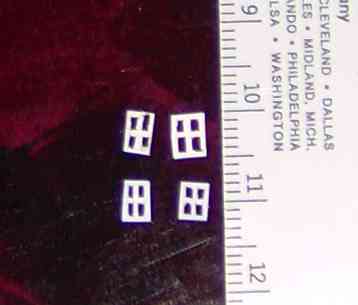
OK, I decided to try to make some myself (since I made the suggestion !) I tried manila folder and notecard (index card) paper, using a #11 X-acto, cutting on a glass plate. I guess the glass was a mistake, as it dulled the blade quickly and made a mess of things. I tried some polystyrene cut from a laboratory weighing dish (approx 0.014" thick) also. After switching to my cutting mat, things got much better. I liked the poly; after making the four panes, and before cutting the whole thing out of the sheet, one could if careful, shave the muntins to make them thinner. To cut out the outside, I simply pushed down with an X-acto chisel blade. Here are some roughly 2 ft x 3 ft windows. Top are paper, cut on glass and mat. Bottom are poly. Coulda made 'em a bit nicer, but had to get back to planking.............. I cut two panes at a time, for alignment, mostly pressing blade down so not to slice too far, cutting four verticals, then the horizontals. I was starting to get a process and a rhythm going. Put on some good tunes and you'll have dozens made in no time(!), or maybe not..... Cheers, Brian
-
Would you consider heavy paper? Such as business-card stock, note cards, manila folder.... These would seem to be a good scale thickness. Brian
-
I understand what you're describing, but it seems some are installed where the back may not be assessible. I'm thinking especially on bulwarks where cannon are rigged. Brian
-
Wee modellers simply glue these into decks, bulwarks, cannon carriages, and such. Just curious....How were these actually secured? Were they threaded bolts with washers and nuts? Configured like a wood screw? Hammer-riveted on the back-side? I've no intention of re-creating these in miniature. Just wondereing how the stresses were handled in reality. Regards, Brian
-
Boots...sleeves...COATS! Ha, I sensed it was clothing related. Thanks shipmates. On the Rattlesnake, I'm sure the tiller opening would be sealed, as the rudder post passes through the captains cabin... Brian
-
Now-and-then (and rarely) I see the rudder opening covered, I assume to seal it from the sea. Was this a normal practice in reality? During certain eras? Certain types of vessels? I seldom see it in models. Would they be tarred canvas or something else? I'm building the late 18th century privateer Rattlesnake, which uses a tiller, not a wheel, and has this opening on deck for the tiller. Normal to cover it? Just during adverse weather? Does these seals have a name or did I guess right with "boot"? Brian (not sure this is in the right forum category....)
-
Jan, Such a georgeous model! The photos through the rigging with the white background are especially striking. Bravo! Brian
-
Yes, if you want to be realistic, more treenails (or representations of) than just at the bulkheads of a POB build. Here's an example from Dan Vadas' HMS Vulture: http://modelshipworld.com/index.php?/topic/230-hms-vulture-by-dan-vadas-1776-148-scale-16-gun-swan-class-sloop-from-tffm-plans/?p=5318 Brian
-
Yes. There will of course be a lump there. You can diminish it somewhat by lightly hammering on it or by forceful pressing. I'm not sure how woolding is done on an actual mast, but if it is done this way, it might be that the lump is "acceptable" to have in a model.
-
When the end after the last wrap is put through the loop on the right in step 3, it is pulled under the wrap, necessarily forming a loop or bight under the wraps. Practice on some dowels. Or a broomstick for bigger scale.
-
This is the same technique as Daniel shows, in diagram form, Used to do bindings on shakuhachi (Japanese bamboo flutes) http://www.shakuhachi.com/Y-BindingRepair.html Regards, Brian
-
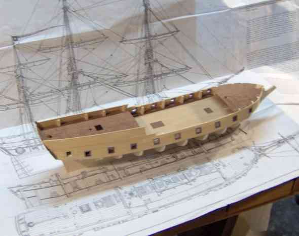
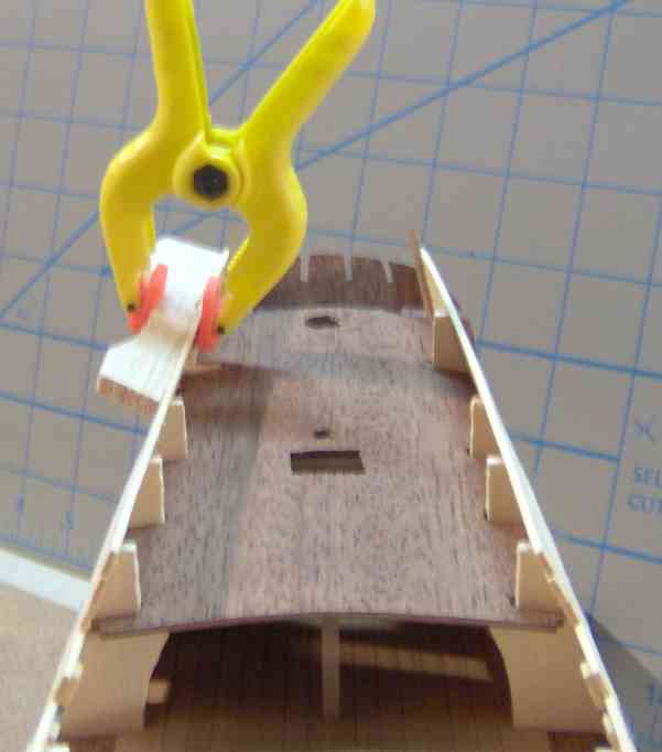
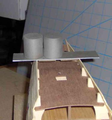
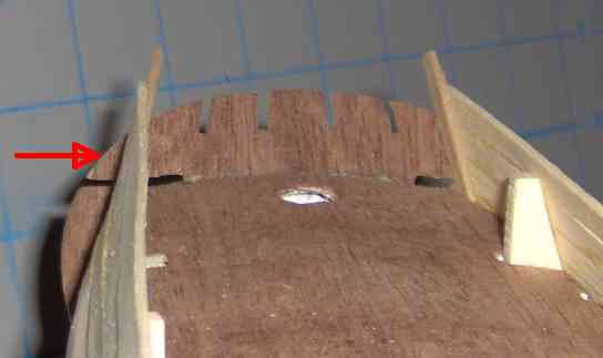
Thanks JP for sharing your experience. As expected, the dry clamping didn't work and I decided to try the water soaking. Rather than clamping, I found I could push the assembly from inside to get a good shape. I used a piece of scrap balsa cut to fit from the opposite bulkhead to its mate. I used a water-soaked cotton swab to wet the area ( 3 planks ), inboard and outboard, avoiding wetting the bulkhead afore and the corner joint aft. I re-wet the area numerous times throughout the evening. You can probably see some of the wetness in the above picture. I could see and feel that the glue was softening and worried about the joint between the planks opening up, I added some weight to maintain contact. So this evening I took off the weights and removed the patented balsa plank-tensioning device. Hey! It worked pretty well! Not perfect, perhaps only some slight sanding to fair it rather than massive filling. Such a relief. Here's a view of the wee frigate ready to move on. Ignore the shortened stem. I had repaired it after one of our cats used it to gnaw on. I recently snapped it off by accident (will pin/dowel it next time) and may leave it off for the time being. Cheers, Brian
-
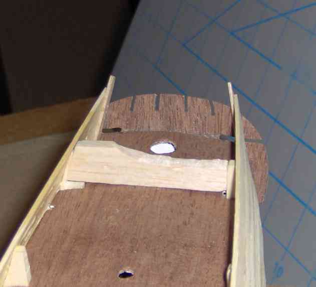
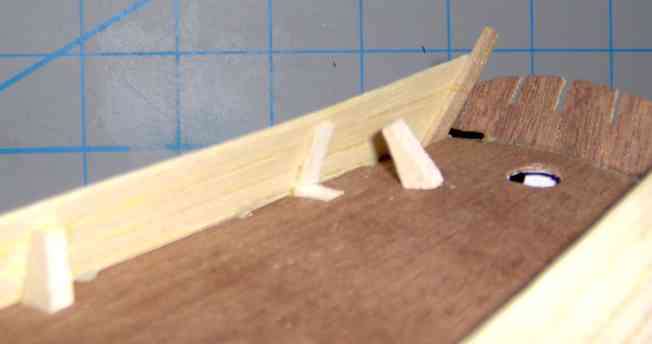
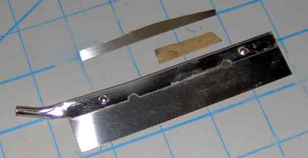
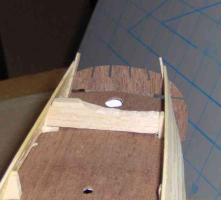
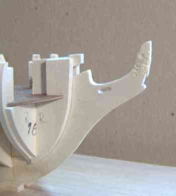
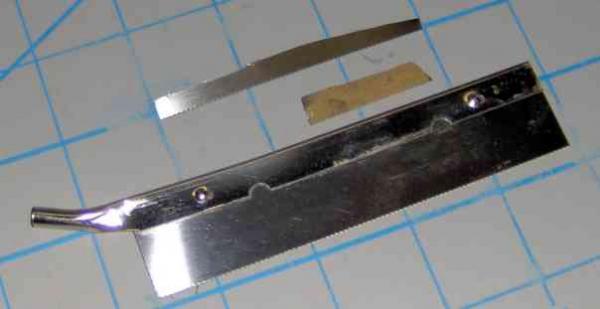
It seems I keep telling you all I'm on the verge of getting to the (first) hull planking. But another (hopefully small) delay..... I had finished the last planks for the quarterdeck rail/bulkhead/whatever. Thought they were sitting pretty; bent well in three dimensions. Unclamping the next day showed the starboard side had a shallow "S" curve rather than a smooth sweeping curve aft. Apparently the bulkhead at that point wasn't properly faired (shimmed in this case) though I had gone over everything a couple times and it looked good (I thought) as the plank was drying in place I thought using a wide area of filler would offend my sensibilities so I considered other fixes. I sliced off the offending bulkhead extension close to the planks and along the deck. This has to be done anyway(!), so no concern. Also continued the lower deck-flush cut to completely sever it from the rest of the bulkhead below. This actually relieved some of the "S". Encouraging. (The first picture is after that cutting.) I've clamped the rail against a curved piece of balsa and am letting it sit, hopefully to conform and stay in that position. Not sure this will work this way (dry). I'd want to do this wet, but I expected that would loosen glue joints (yes/no?). Suggestions welcome!! To cut the bulkhead hunk out, I used an X-acto saw blade piece that I've cut from a stock saw. I don't recall how I made it. Probably cut with tin-snips and the cut edges cleaned up with a file. Really really really (REALLY!) handy. Flexible. Makes nice flush cuts, etc. Here are a couple pieces. Regards, Brian


-
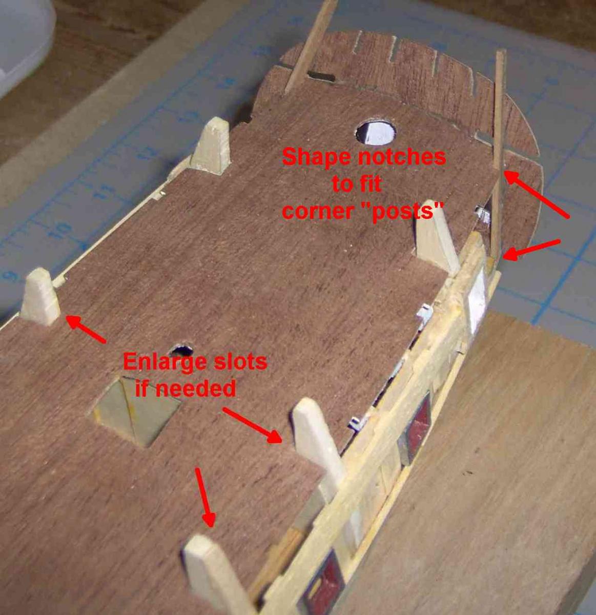
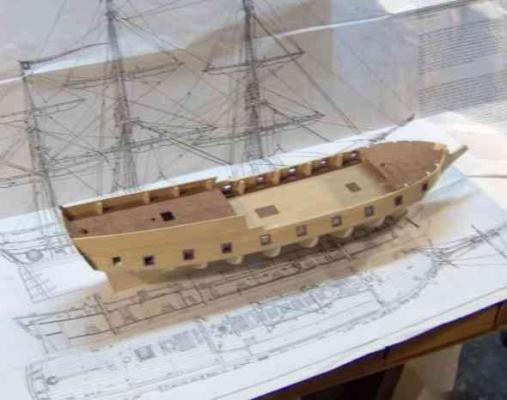
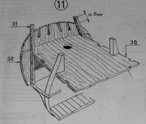
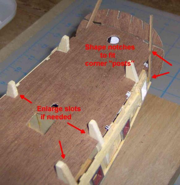
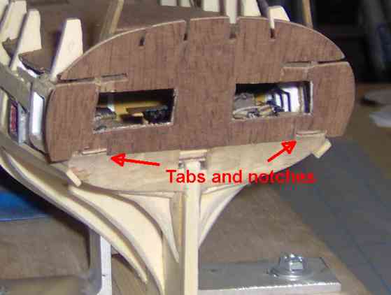
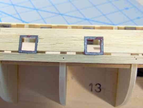
Here's a bit of an update. I had intended to wait until I got a little further, but we need more 'snake stuff here! So while some glue dries........ I've installed the false quarter- and fore-decks and the transom and have done the 1st planking between the gun ports. Sooo...tips and tidbits for Mami RS builders and some baring of my boo-boos The false decks and transom piece (these are thin mahogany) should be soaked, formed over a curved surface approximating the camber, taped down and allowed to dry, I guess overnight would be good; my q-deck was taped down several months during my hiatus from building! Many months ago, looking ahead at the instructions, I read one is to "6) Glue....the halfdeck 30 [quarterdeck], the stern strips 31 and the transom 32." At the time, I pictured having to do these all at once, rigging some fancy clamping, and applying just too much pressure and having it explode apart.......... Silly me. I managed to do each of the three separately, in that order. However, the tabs at the aft of the q-deck, ended up slightly lower than the mating slots in the transom. So DO use the transom or other placeholder to keep the end of the deck up. I ended up removing the tabs and leaving it as it lay. Too little difference to fret over. Oooooh, almost forgot... The quarterdeck has not only camber ( a side-to-side curve), but it's long enough to have a sheer curve (front to back). The middle, between the mizzen-mast hole and the hatch, needs to be clamped/held down to the bulkhead underneath when gluing. The slots in the false deck that fit around the bulkhead extensions may need adjusting, from poor manufacturing, misplacement of bulkheads, or both. NO problem. Feel free to open up the slots as required to fit all the bulkheads AND to center the deck. I had to adjust several. Any gaps will be planked over or other wise covered later. The corner notches in the two decks for the stern posts/strips (31) will likely need to be opened up to fit. Angle the bottom of 31 and bevel that end (it angles inward) for a better glue joint. After installing the transom ply piece, I noticed it was a hair off-center. Should have eye-balled the trial fit for that aspect of alignment and adjusted the tab-in-notch fit. Again, I'll just make little adjustments to compensate; no problem. THAT completes sheet 1 of twelve sheets of instructions! (Two sheets on each large fold-out). 1-4 are hull, fittings, etc; 5-9 are rigging; 10 is parts templates and dimensions; Table "A" is views; "B" is masting and the rigging thereof. Earlier, the first layer of planking was initiated in installing the ports. Apply one row of planking (5x1.5mm), its lower edge lined up with the lower edge of the false deck. Use the metal gunports themselves to give the spacing for the line of planking just above them. At the stern, I was not careful to keep this lower edge to lower edge alignment on one side, so the aft-most ports aren't quite level port-to-starboard. Not noticable unless you look at the stern and rock your head back-and-forth ( so DON'T DO THAT!!). I've added a wedge/sliver of planking to the higher side to make both sides nearly level for the upcoming 1st planking of the hull. The drawings conveniently show that two first-layer (5mm) planks fit neatly to fill between the gunports. At Dominik's Rattlesnake build, it looks as that is so. HOWEVER!!! my ports seem to be 11.5 mm, and I've had to add some narrow strips to make up the difference. I've done that, and am doing the first layer of planking on the quarterdeck rail. THEN, I'll do the first layer of hull planking, trying to use 2nd-layer planking technique for practice, having never ever ever having done this stuff before. I have access to a number of planking tutorials/books,... Blessings to MSW and and its vast collective knowledge............. Regards, Brian
-
Haven't tried it. But if the silicon carbide (or whatever) rock-polishing grit is too severe, you might try what's used for cleaning/polishing brass cases for ammo re-loading --- corn husk or walnut shell pieces. I can imagine it being a nuisance separating your blocks out of those natural colored media! Brian