RiverRat
-
Posts
206 -
Joined
-
Last visited
Content Type
Profiles
Forums
Gallery
Events
Everything posted by RiverRat
-
1799 was after the war for independance, so a different Enterprizse or commisioned later as a navy ship. Brian
-
 Ferit. I'm chiming in with praise for your hoops! You must make an instructional video of your technique. The first episode of MSW-TV!
 -
On p.4 of my build log is a stern view of the Admiralty (I think) drawing. It has a slight but apparent arch, much like the deck camber and not as much as the carved decoration, but that little bit makes a world of difference in appearance (to me at least).
-
Yup, fully aware of that. But concerning an ugly taffrail that might be like what Janos was thinking of...for example:
-
Very good! Thanks for the discussion and drawings gents. I had thought mirroring the camber might look more "elegant", but horizontal it is. Janos, your "ugly" rail reminds me of a couple of Rattlesnake taffrails I've run across. Those would certainly scream to be camberized. Brian
-
Title says it. I'm approaching a point in my 1780s privateer Rattlesnake build where I may need to keep this in consideration. Are the top surfaces horizontal side-to-side or would they match the deck's camber? Maybe not a significant detail, but, well y'all know how nit-picky we can be sometimes.......... Brian
-
Hi Martin, Glad you missed the tornados. A safe room! Is this specially built or just the best you have on hand? Cutting little pieces, trying to get the lengths and angles right (or close enough, and I discounted miter joints immediately!), and handling them with fine forceps wasn't exactly easy! ...which is why I put the adhesive on the plastic. If I re-do these, I might try to hold them with tape and apply the adhesive to the wood instead so there wouldn't be as much excess. The tiny pieces are guaranteed to fly out to parts unknown if I handled them with forceps I've started a bit of the second planking above the wales; may have an upcoming update after a few strakes on. Brian
-
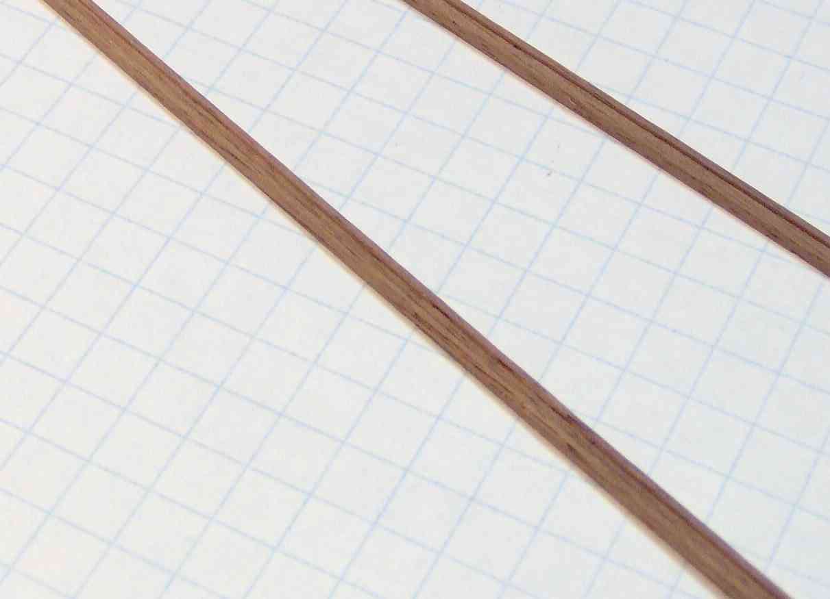
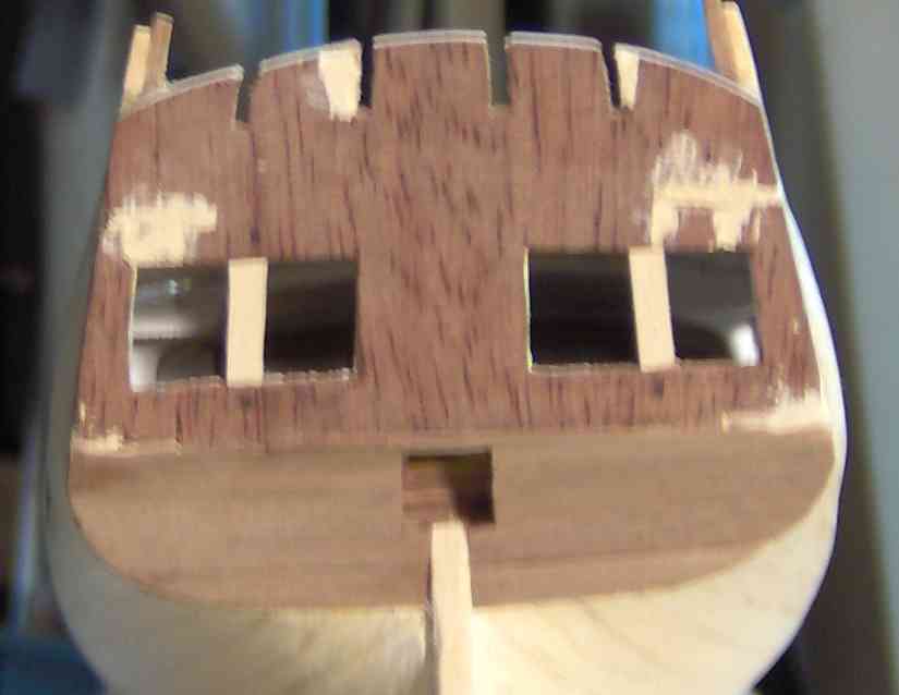
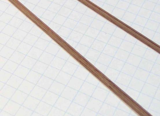
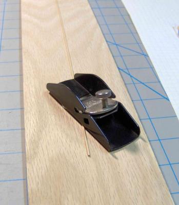
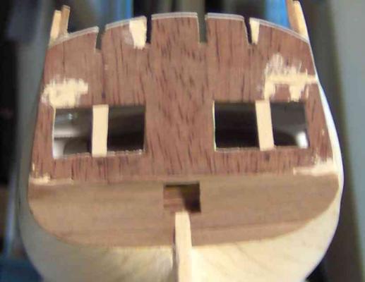
Another jump backwards to re-do the rudder. I had mentioned before that some of the non-square view drawings in the plans were sometimes ambiguous or poorly done. The drawing of the rudder assembly gave me the impression that all the cut-out areas for the gudgeons and pintles were parallel with the waterline. When I made it this way, it just struck me as odd looking. My earlier pictures might show a hint of it. After looking at some of the scratch builders' rudders, I've removed the offenders and have more appropriate shapes; top of the "cutout" is square with the hingeline and the bottom is angled for relief to ship/unship the rudder. The general side-view drawing of the model (which I failed to consult at the time) does show all the cuts square with the hingeline, but doesn't indicate the sloping lower cut. Here, I'm in the process of opening up the transom for the lights. A piece of clear plastic with the frame limits drawn, and the plastic inside that area removed to allow me to cut and sand with the drawing in place. I drilled an outline of holes with a pin vise while watching the coverage of the violent storms coming through the area (lots of high winds and rain but thankfully no tornado here) and used an X-acto knife to oust the middle. I had gotten hold of some of that Tamiya model masking tape in 6mm. Great stuff! I used it to mask along the glue lines for the lower transom trim pieces (1mm boxwood) to make glue clean-up easier. And it flexes enough that masking shallow curves, like these two pieces, is easy. Here are the lights, not glued in place, with a paper printout of Hahns carving for my amusement. I'll be designing my own, but would add it much later. I may get a fresh batch of that RC56 adhesive to see if it's thinner than my old stuff and may remake the lights if so. While you can't see it without really close examination, there are some heavy areas of squeezeout, though clear, and I wasn't prepared to clean up at the time of assembly. Kind of tough to scrape within a 3x3mm space without having something ready to do it. Another failure to think ahead! I've made some 1.5 x 3 mm "C" moldings for the first strake of the second planking using a razor-blade scraper as found in the "Relief Mouldings" topic: http://modelshipworld.com/index.php?/topic/516-relief-mouldings/?hl=moulding#entry6017 Should be titled just "Mouldings" I think......... Not especially clear with my older digital camera. I need to invest in a better one (that I can control - I used to be whiz with my Nikon SLR and collection of lenses.....) Brian

-
Hello Elmir, The profile view of your vessel caught my eye when you first posted. Such an interesting subject and your build is looking great! It's also a treat to see another working/traditional vessel among the ubiquitous warships! Regards, Brian
-
Yes, you are certifiably insane . (But in a good way....)
-
Suggestions for "entry level" kits
RiverRat replied to Spaceman Spiff's topic in Wood ship model kits
Hey there Spiff, A thread you might want to look at is: http://modelshipworld.com/index.php?/topic/2406-what-is-entry-level-in-the-world-of-wooden-ship-building/ It might give some suggestions for you. As far as a resin kit build log, there certainly are some, perhaps not many, but feel free to get one started! All are welcome. Wood, plastic, paper, bone, shells,.......... Brian
-
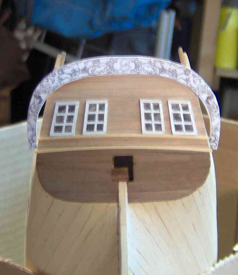
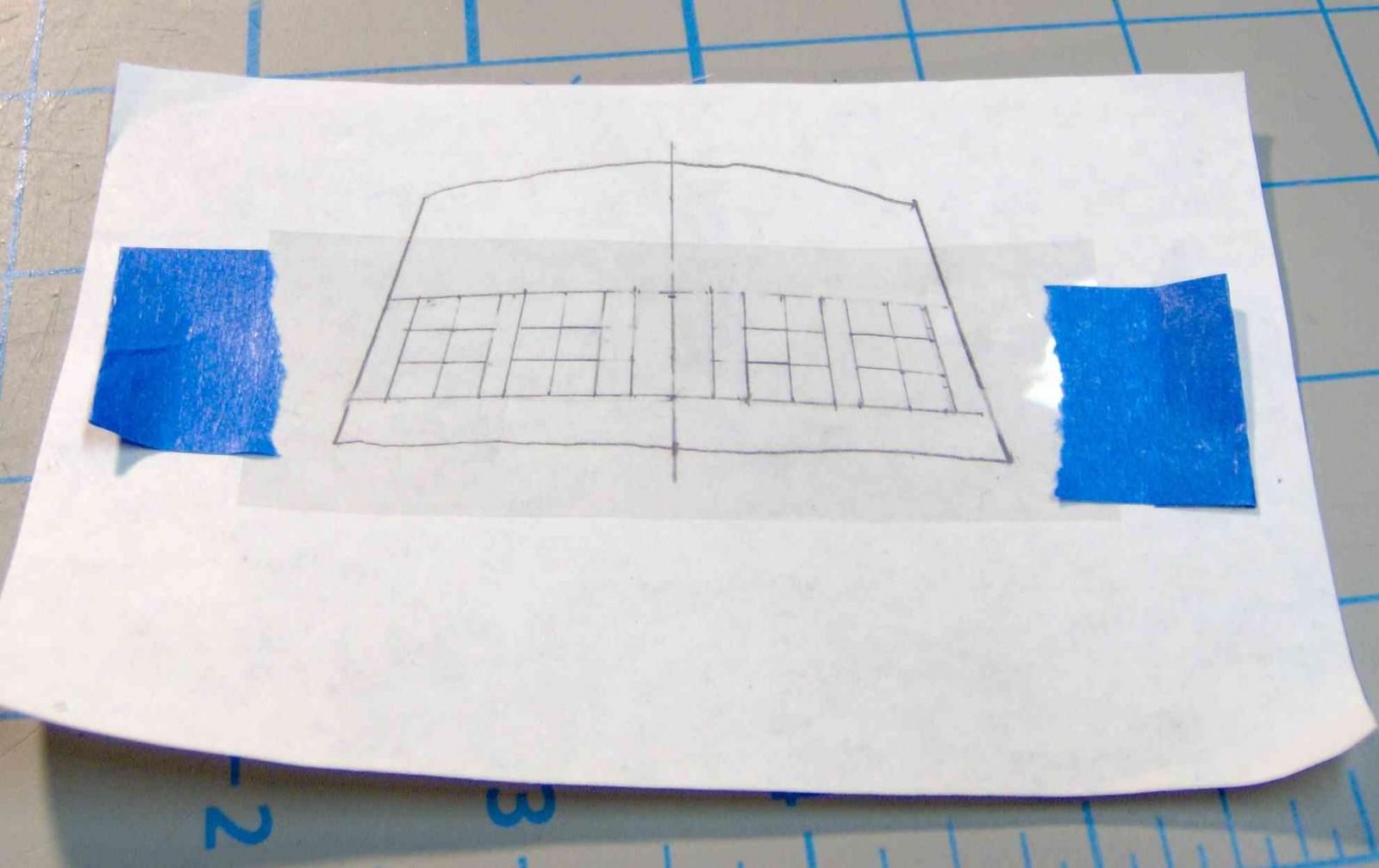
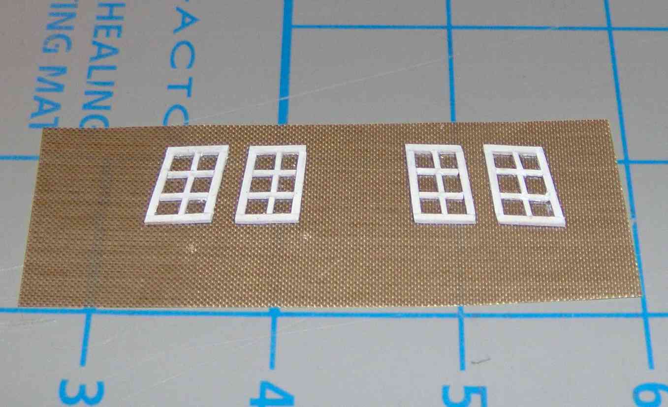
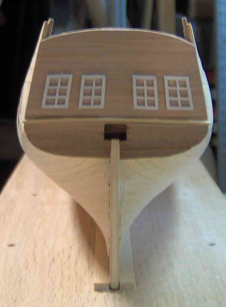
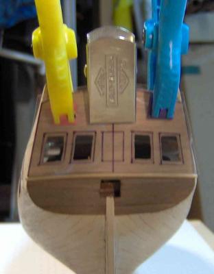
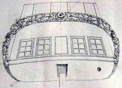
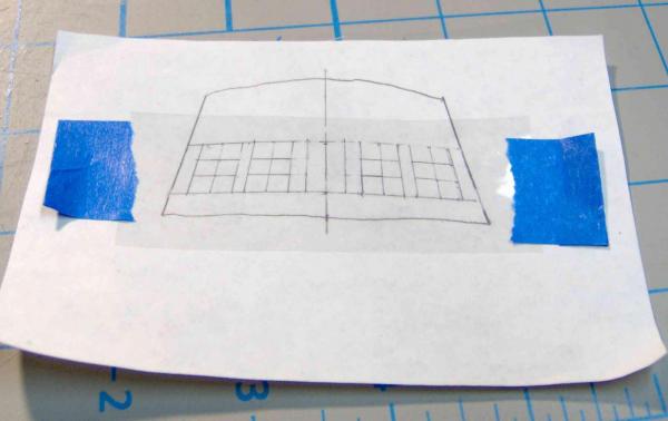
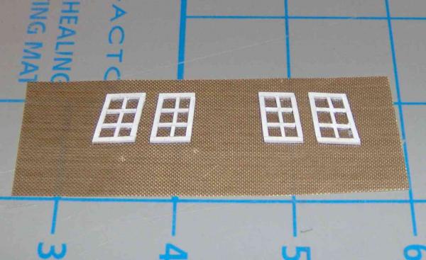
Yves. Thanks! I've been finding, though, that most of the detail is lost with the deck above and the transom installed. Without something like LED lighting inside, which I'm not doing, one only gets a hint of the contents in the cabin. That's Ok with me; I just didn't want to have bare kit bulkheads visible in case one actually could get a good view inside through the stern and quarter lights (windows). demonborger. Yes, the inner wall of the bulwarks get horizontal planks. It's probably not a difficult fix; I was just noting my lack of experience and foresight at the time I built that section. More lack of foresight to come, I'm sure! UPDATE Back-tracking a bit --- Before I had got much of the first planking on, I decided to add some stops to the side of the mast slots in the ply keel to limit side play of the base of the masts. I had this probably unfounded worry that a mast might slip sideways out of the slot and drop down into the hull. These were just some glued bits of wood or ply, left and right of the slot, that would allow some side-to-side play but not enough for the mast to leave the keel. Sorry, no photo. Another Mamoli RS builder, I think, mentioned cutting down the size of the obtrusive ply bulkheads supporting the aft of the forecastle. Good idea! I did likewise, at least half cut away, and put some dark stain on them. They will be hidden even more when the bulwarks are planked. No current photo here, but I'll likely show it later. TRANSOM LIGHTS (Sometimes I worry about my properly calling the ship's windows "lights", as there might be some newbies reading these, and think I'm talking about lanterns or something! ) While early on I planned on making see-through windows instead of using the kit's metal part, I had no definite PLANS in mind until I got to the point of making them. Insetting them, or flush with the planking might look better, but I decided on surface mounting low profile frames. First, before planking the transom, I had to refill a part of the big openings I had left in the mahogany false transom. Needed the support between the lights. Transom was then planked with 1x3mm cherry. I had ordered some 1mm x 1mm boxwood strips along with the other woods replacing some of the kit wood. I used a small plane to thin some of this down to about 0.6mm to be used as the outside of the frames. For the muntins, the strips separating the panes, I similarly made some 0.6 x 0.6. Longish strips of these were pre-painted (white acrylic) on three sides. The bottom was kept free of paint by sticking it to painters tape, the tape peeled away carefully right after the coat. From a tracing of the transom shape, I laid out the lights to arrange them similarly to that in an Admiralty drawing: I'm using clear .002" mylar for the glass. This may be similar to the clear plastic sheet protectors you can get where office supplies are sold. The adhesive I'm using for the wood-to-plastic is Super Z RC-56, a canopy glue used most often for RC planes. Looks like white glue (it's not), but dries clear and is flexible. The bottle says it's an excellent adhesive for vinyls, plastics, fabric, wood and glass. I did a test on some small pieces and it bonded well. I could peel it apart, but I'm confident of it for a static, unloaded part. This bottle, though never opened, was a few years old and the adhesive was a bit viscous/thick and hard to spread thinly. I managed OK, but after using it, I read some reviews and learned that it was actually thinner than white glue! So! Fresh stuff for next time. I taped the clear plastic over the paper layout and built the frames on the plastic, scuffing the bondlines a bit with a narrow diamond file for a little more adhesive bite. Each light is 9 pieces. Top and bottom horizontals, two sides, these all 1mm x 0.6mm; two full width muntins, and 3 small vertical pieces in the center, these 0.6 x 0.6. Done in that order. Adhesive was goobered on the bondline and the cut-to-length piece set in place. After curing overnight, the lights were trimmed aroung their periphery, leaving the painted wood light on top of a piece of clear plastic. Cut ends and some joints were touched up with acrylic. The cut-outs in the transom are (hoped) to be slightly smaller than each frame, the frame (the plastic underneath) bonded over the opening just under the frame outline (did I explain that OK?) with RC56. The cut-outs aren't done yet, but just for grins, here are the lights temporarily tacked to approximate position. One of the two pieces of horizontal trim has been applied. On the kit's metal piece, the "Rattlesnake" name fits between the two. Sheesh! Enough already! Hope I didn't bore you much. Regards, Brian

-
Thank you all for the lovely birthday wishes! I was going to give myself a birthday present by getting to "such-and-such" point in my build, and post an update, but didn't quite get there. But, I'll post what I have when I get back into port later today. In the meantime, I left a cask of rum and some vittles in the captains cabin for the party guests. Until I return........
-
A question on working mizzen lateen sails
RiverRat replied to Stevinne's topic in Masting, rigging and sails
That ship looks familiar! See: http://modelshipworld.com/index.php?/topic/2311-nina-and-pinta-reproductions-at-grafton-illinois/ Brian -
Hi normy, Yes those are likely millimeter units. Instead of converting each and every one, get some scales/rulers in millimeter or centimeter units (10 mm = 1 cm). It'll save you a lot of trouble. Might be able to find some at an office supply store and I know there are scales that can be printed out that are available on the internet. For example: http://www.vendian.org/mncharity/dir3/paper_rulers/ Brian
-
My current workshop (in a box)
RiverRat replied to TK1's topic in Modeling tools and Workshop Equipment
I LIKE it! We have a cat that has a compulsion to grab anything off of shelves and bench tops that it can reach, and I've had to go through a number of protective measures to keep tools and parts from its prying paws and teeth. A kit like yours would be handy. Brian -
Hey, it's your choice as for as color, grain and texture, and what appearance you hope to achieve. I'd also prefer 3, though,....straighter grain, more consistent color. All seem too coarse to simulate scale wood grain, but that's an eternal curse to modellers, ain't it? Brian
-
Thanks JPett. I'd downloaded the MS instructions long ago and now remember seeing that joint, but I'll be sticking with my plan to overlap the counter rather than trying that miter. This approach seems to have been approved by several, so I'm quite OK with it. Hey, got my replacement wood today (some of the kit wood was ratty) and will get to the second planking soon. Brian
-
Know anyone who makes native american style flutes? Some of your pieces look long enough. Brian
-
Dan, With Allan's additional cant question..... What were the pins like that secured them, what were they made of, and how were they configured that they could be removed (and presumedly inserted/re-used). Sorry if this is nit-picking, but it really does interest me..... Brian
-
I just finished reading this series of 20 novels and a published unfinished manuscript. I'm saddened, despondent. depressed, in the doldrums, and heartbroken that this was the end of the series, that Mr. O'Brian passed before finishing the one, and that the series won't continue indefinitely. Wonderful writing, characters you get to know in depth, some of which you emphasize with and even become concerned about their outcomes. Outstanding reading even if you're not a fan of historical novels, the Napoleonic era, or seagoing life. Oh! Ship-modelling content! You'll find a wealth of information on ship handling, life on a sea-going vessel, and such that could be of use to detailng a model to make it come alive and add more character. Your humble and obedient.......... Brian
-
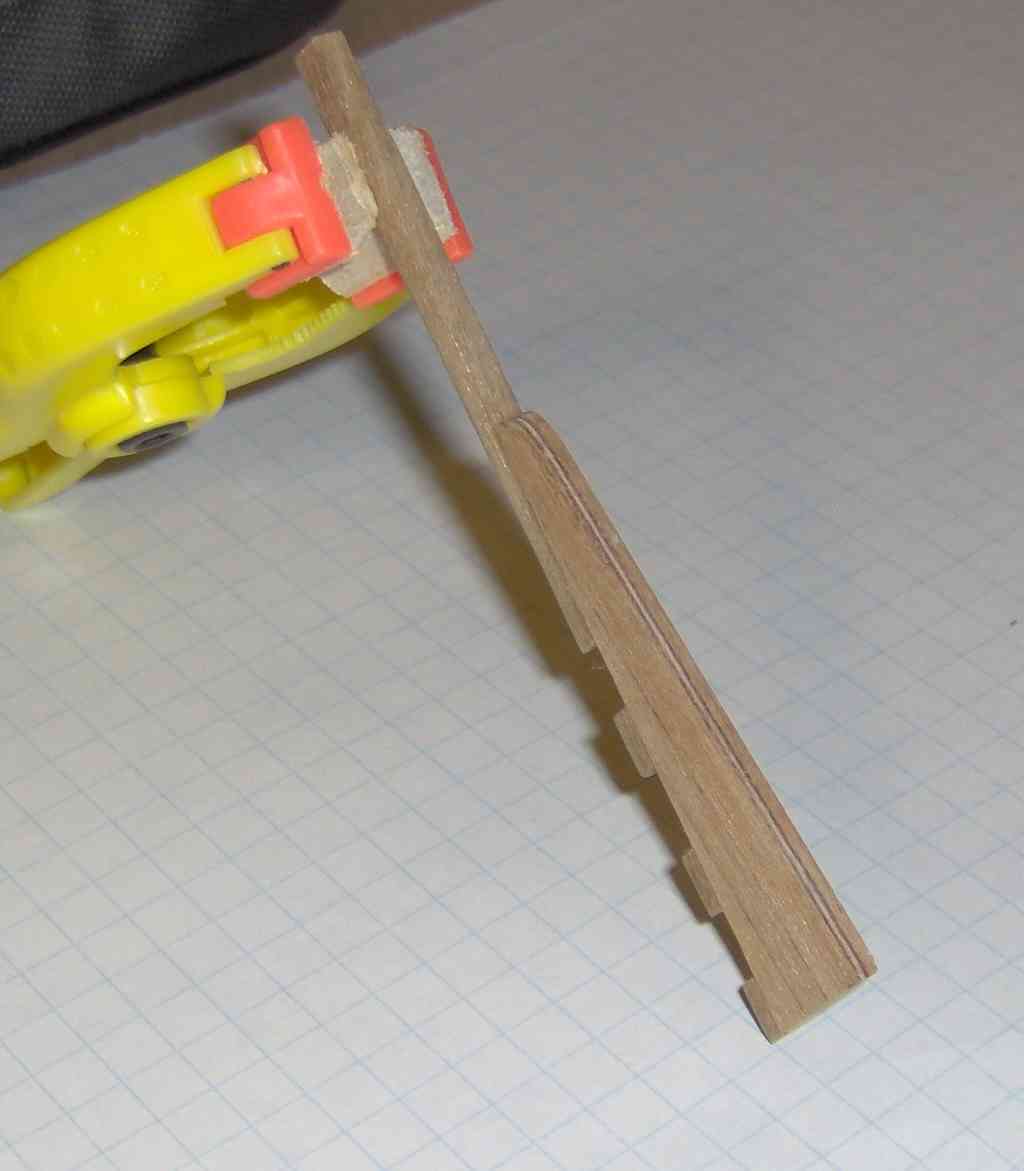
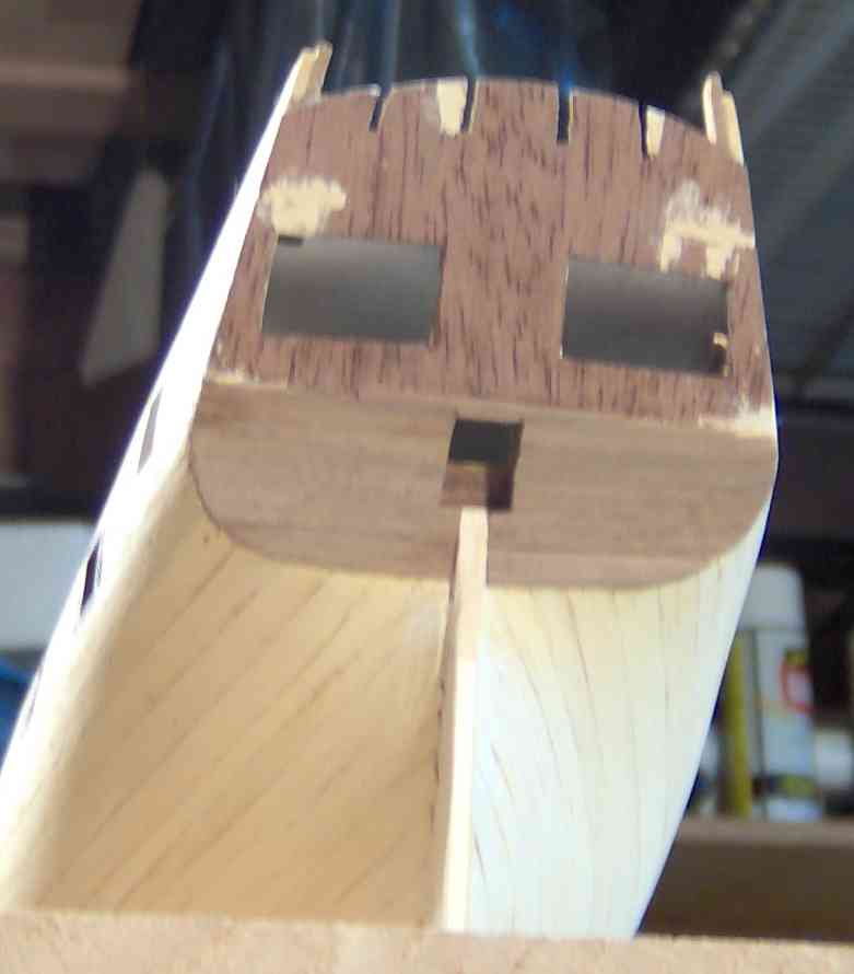
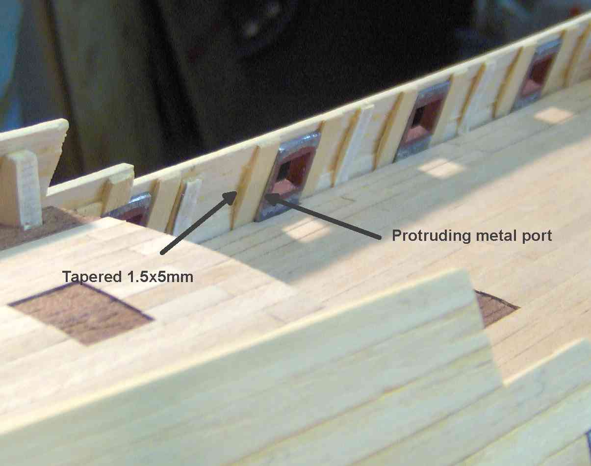
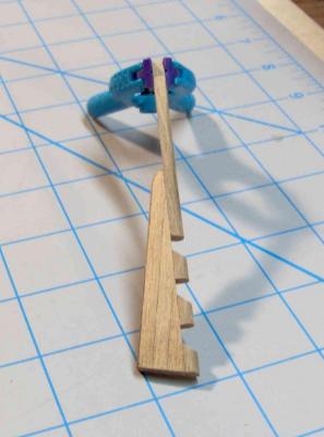
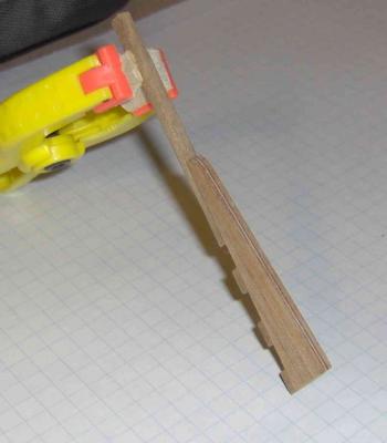
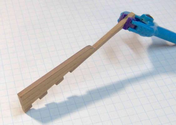
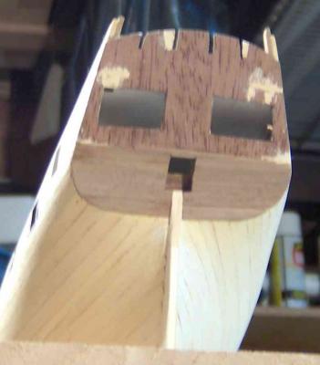
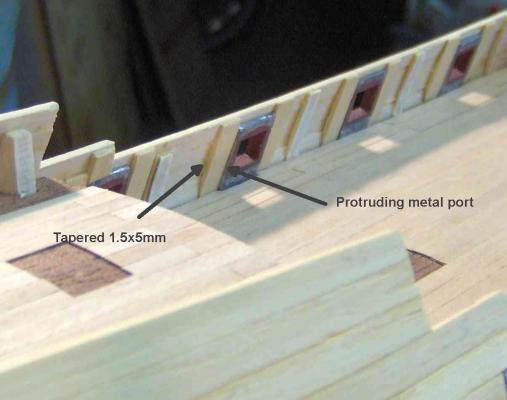
Should get some new wood in a day or two for above-the-wales planking. Here's an interim update. I can plank the counter with what I have, but wanted to make up the rudder to make sure of clearance. It's walnut built on a mahogany-ply pre-shaped base. Acchh! It has a light layer in the middle of the ply. I thought of staining at first, but decided to cover it with some 0.5mm walnut. Better, but not as seamless as I'd hoped. Will likely be painted whitish below the waterline anyway, unless my lower-hull planking miraculously comes out nearly flawless. Planked the counter, but first dabbed some dark stain on the exposed light wood and ply inside the rudder opening (port?). Patched with filler the delaminated spots on the brittle mahogany-ply false transom. To future Mami RS builders and maybe metal gunport users.... Looking back, I wish I had bent the upper and lower tabs on the metal ports inward a bit, to fit better the inward curve of the bulwark. A couple protude inward a little and I may have to do a little fussin' and finaglin' to get the inner planking to fit well. Something I DID do, now wishing I hadn't, was to taper the vertical 1.5x5 pieces alongside the ports, to fit the bulwark curve. Should have used bent pieces to fit, leaving them full thickness. Cheers, Brian
-
Hi David, Try to use wood glue (PVA) when you can. Reasonable working time and a strong bond. I would suggest "medium" CA (5-15 sec) if you need something quciker on a spot that's, for example, difficult to clamp. I would reallyreallyreally avoid the "thin" CA (3-5 sec). It wicks to a great extent and may create an area that won't take finish like the surrouding areas not affected by the CA. Brian
-
OK!! Thanks Chuck for the terminology verification. I had looked up definitions and pictures ( on the internet ) for these two terms before, and vagueness prevailed. Thank you all for your input. I'll be doing stern planking first in this case, though it's not necessarily universal. Stuns'ls alow and aloft! Brian
-
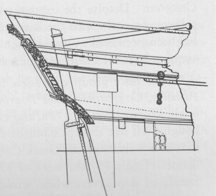
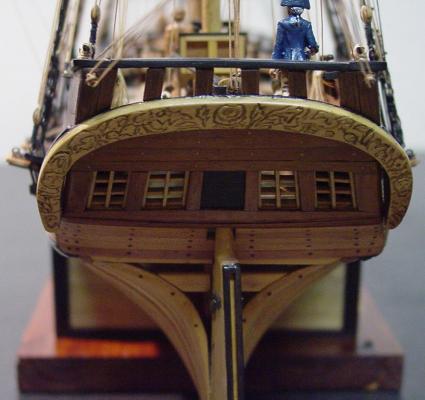
Hi Chuck, I have a copy of that stern pic, but the one I have is not very clear. I may not be using the terms "transom" and "counter" correctly. I have been using, wrong or right, transom as the main part with the lights/windows, and counter as the undercut below that. Here's a side view of the RS stern: Set me right here! What's the correct terminology for these two areas of the stern? Thanks, Brian