Osmosis
-
Posts
626 -
Joined
-
Last visited
Content Type
Profiles
Forums
Gallery
Events
Everything posted by Osmosis
-
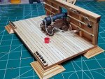
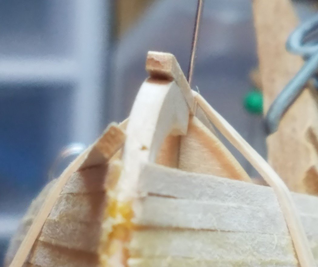
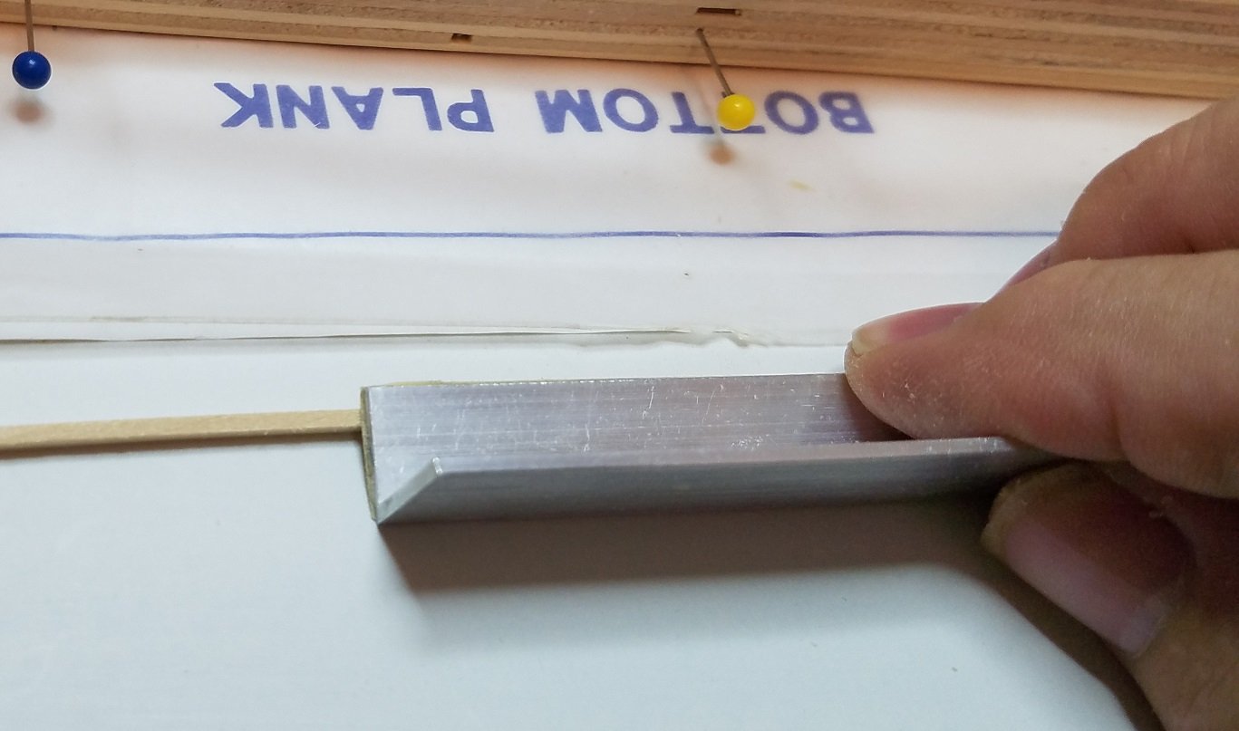
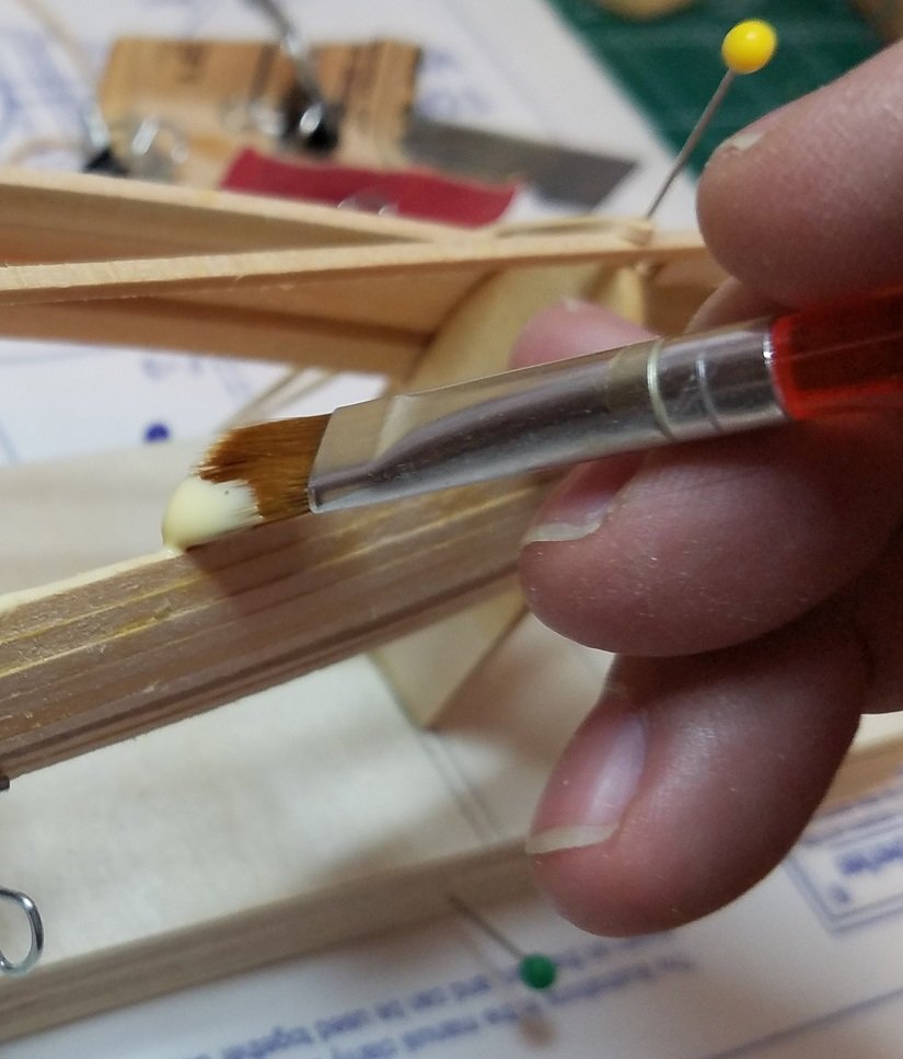
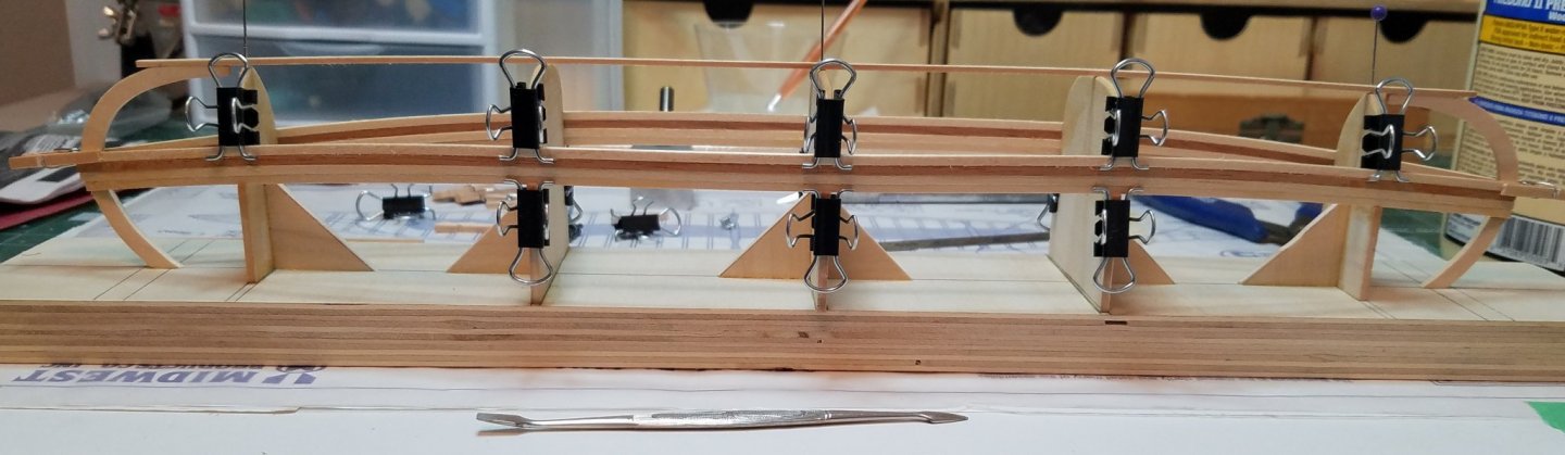
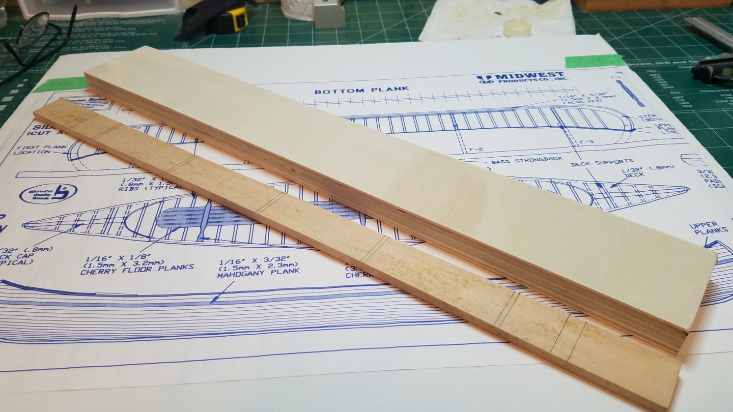
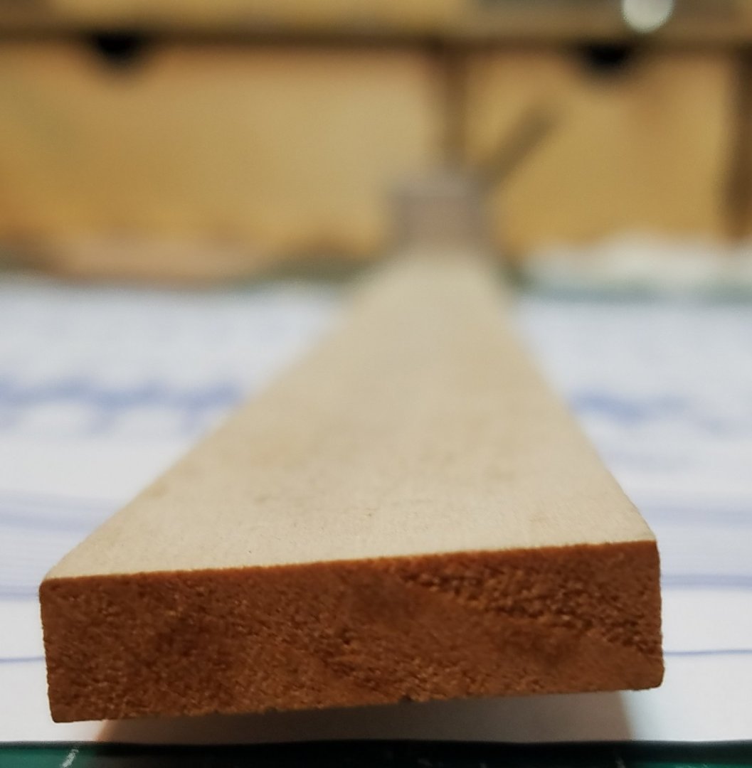
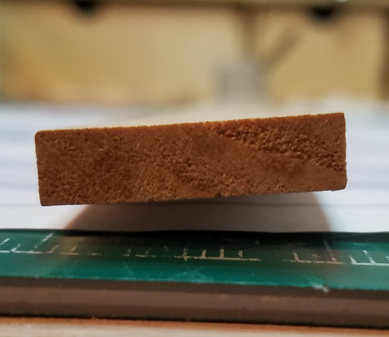
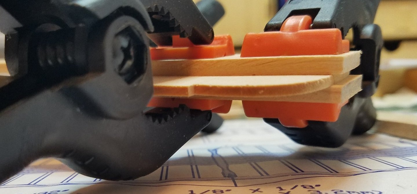
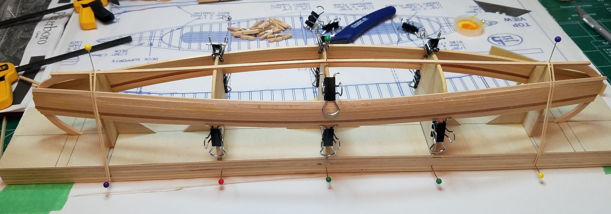
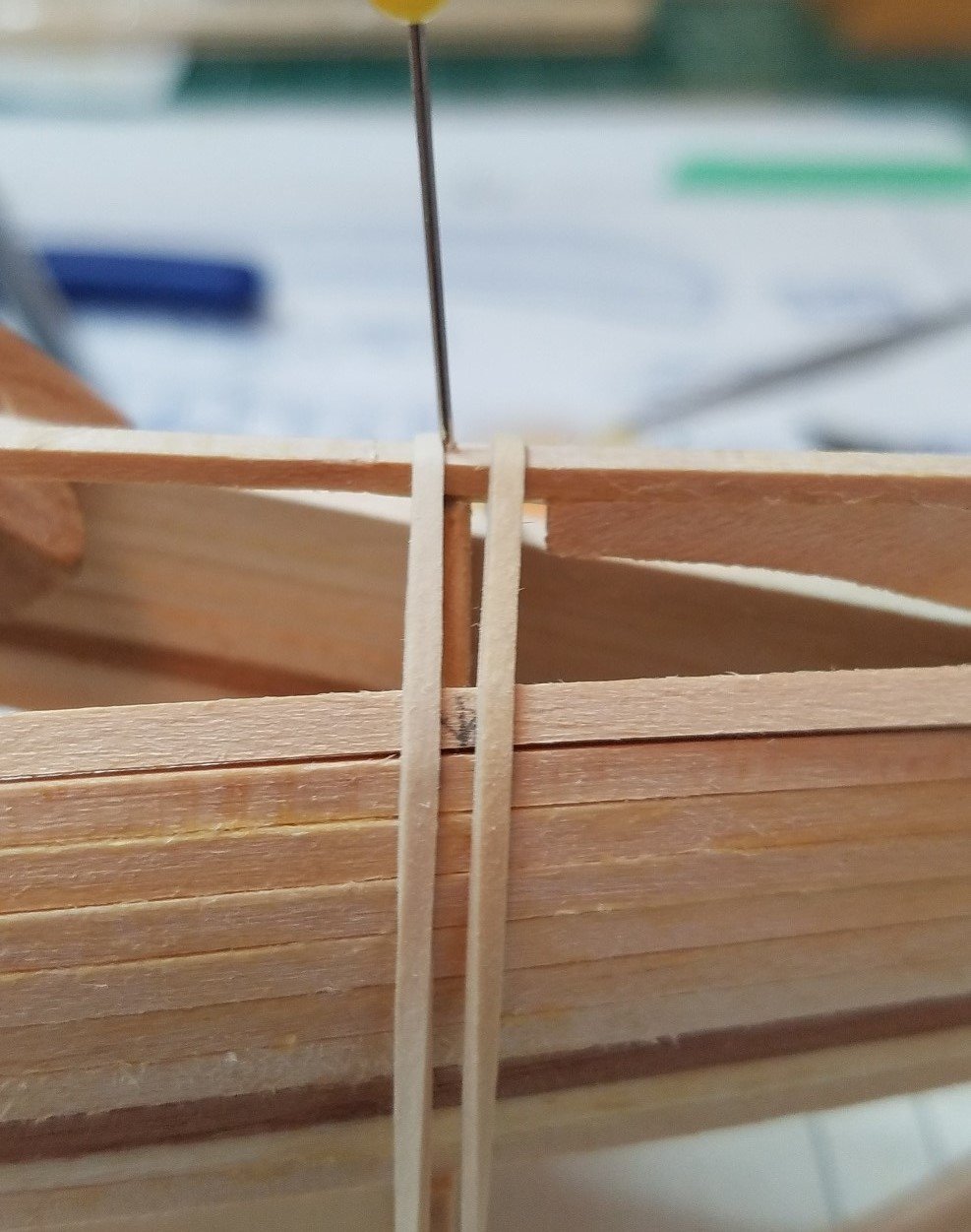
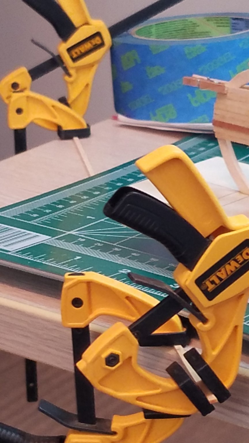
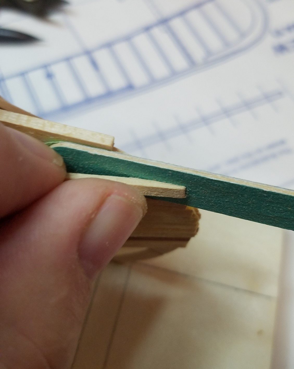
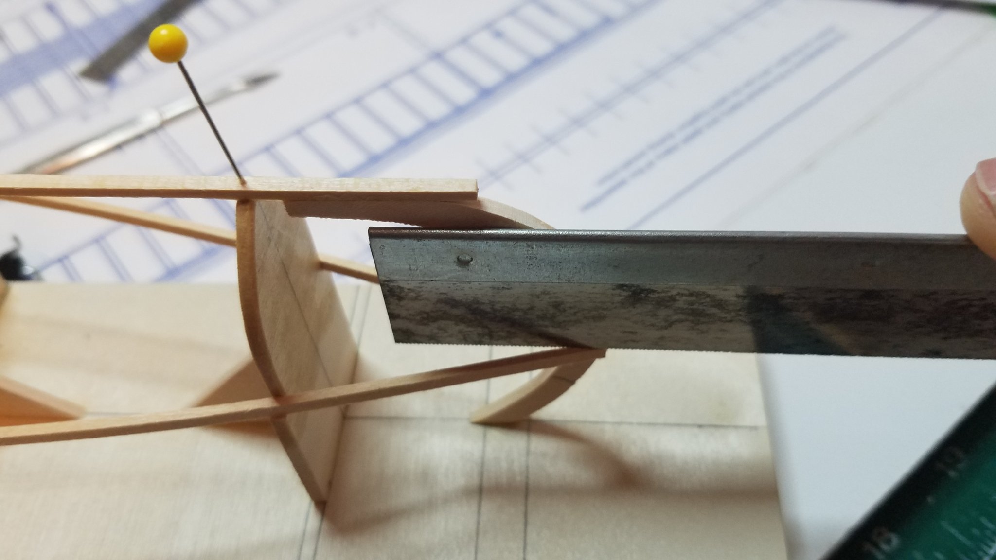
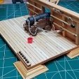 The planking is getting much harder at this point. But I think I have worked out a sufficiently over complicated system for getting through it. The problem is that there is quite a bit of twist needed in order to get the planks to lay right while transitioning around the "bilge turn" to the flat bottom and that twist is all in the final 2" of either end of the plank. Add to that the size of the plank 2mm compared to the size of my sausage sized fingers and well forget trying to twist and shape it in place. So here we go my Rube Goldberg ( you younger guys will have to ask your Grand Parents who Rube Goldberg was) planking method. Here are the three main tools I have been using. Left to right, An old cuticle tool mostly for scraping excess glue, an emery board with masking tape on one side and a small piece of 3/4"x1/2" aluminum angle with a piece of 120 grit sand paper glued to the 1/2" side. You can also see all the various clamps and rubber bands and other clutter laying around. Step 1. Dry fit the next plank and cut to length leaving approx 1/8" over on each end. You can see here the amount of twist needed. Step 2. Mark an arrow at the first frame on each end pointing toward the previous plank. Step 3. Wet the area between the arrows and the ends of the plank simply by holding under running hot water for a few seconds. Step 4. Very gently clamp to a flat surface. The wet basswood compresses very easily. I used the corner of my workbench. Leaving the ends hanging over the edge. Step 5. Using 2 more clamps very gently grab the extreme ends of the plank and twist in the direction of the arrows. Step 6. Brace the clamps in that position and let dry for 15 or 20 minutes. Step 7. Place the plank back in position. Step 8. Using the emery board with the taped side toward the keel so as not to damage it carefully taper the ends of the plank until they seat flush against the keel. Step 9. Remove the plank and place on a flat surface with the arrows pointing up and facing away from you. Using the aluminum sanding block as shown, one edge resting on the work surface and the other riding on the top of the plank. Bevel the top edge. Step 10. Use a small paint brush or you own favorite glue applicator apply a small bead of PVA glue ( I am using titebond II) to the top edge of the previous plank. Step 11. Place the plank in position. Step 12. Clamp the heck out of it and go have a samich or something. a I know this seems like a lot of extra work and it is but it sure makes the planks lay right into position with very little gap. I am at least satisfied that the result is worth the effort. My next plank should be dry by now so I better get back to it. Regards
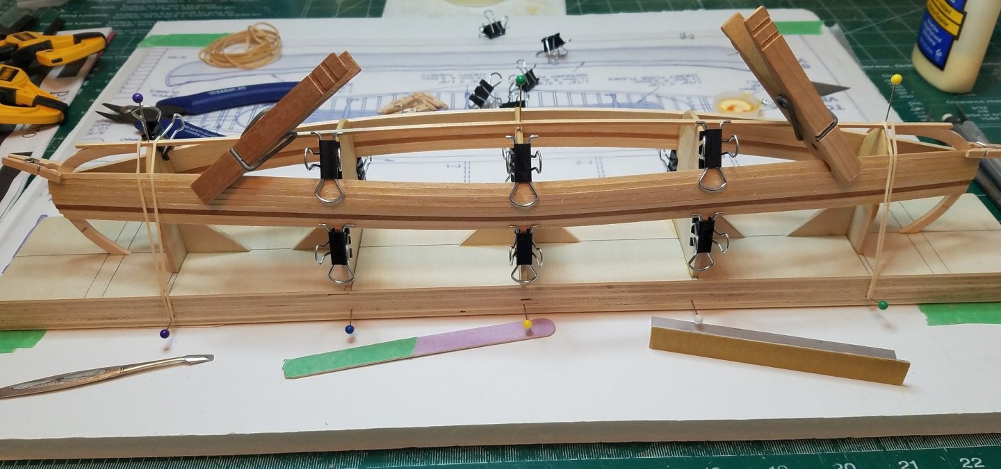
.jpg.5eff21d462dd5a69e13eb81154833026.jpg)


- 84 replies
-
- 7
-

-
- peterboro canoe
- Finished
- (and 1 more)
-
I like it because it gives me a few minutes time to make any adjustments. Some people prefer CA and I use it in certain applications but you need to be sure you have the parts in exactly the right alignment because you only get one shot at it. For planking and finicky stuff I prefer to have a little more time to get the parts where I want them.
- 84 replies
-
- 3
-
-
- peterboro canoe
- Finished
- (and 1 more)
-
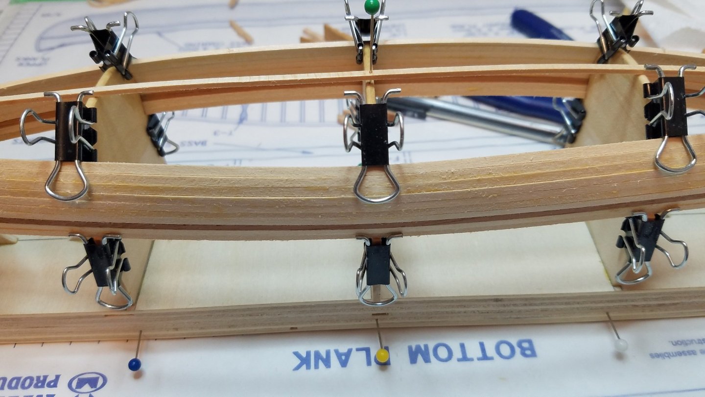
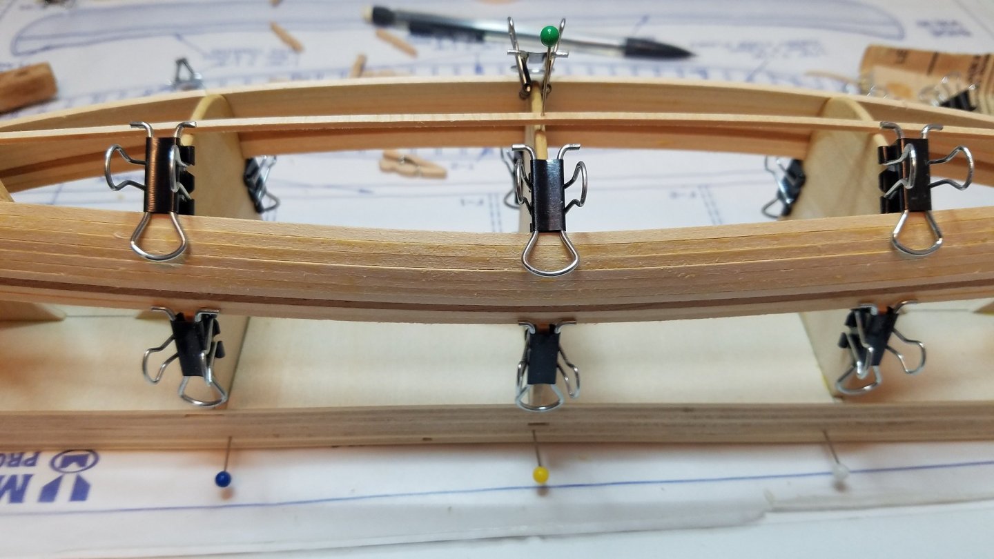
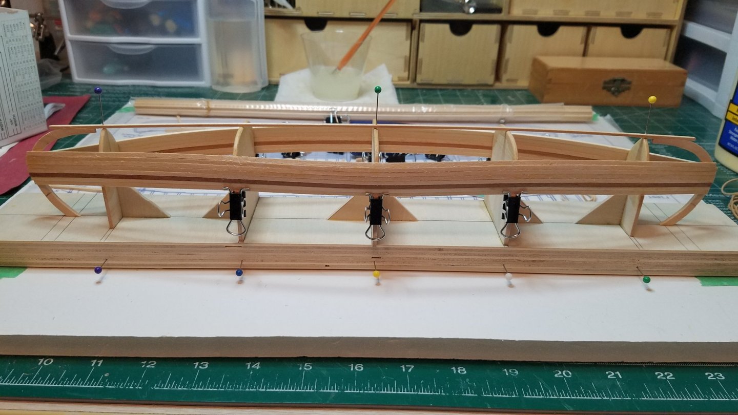
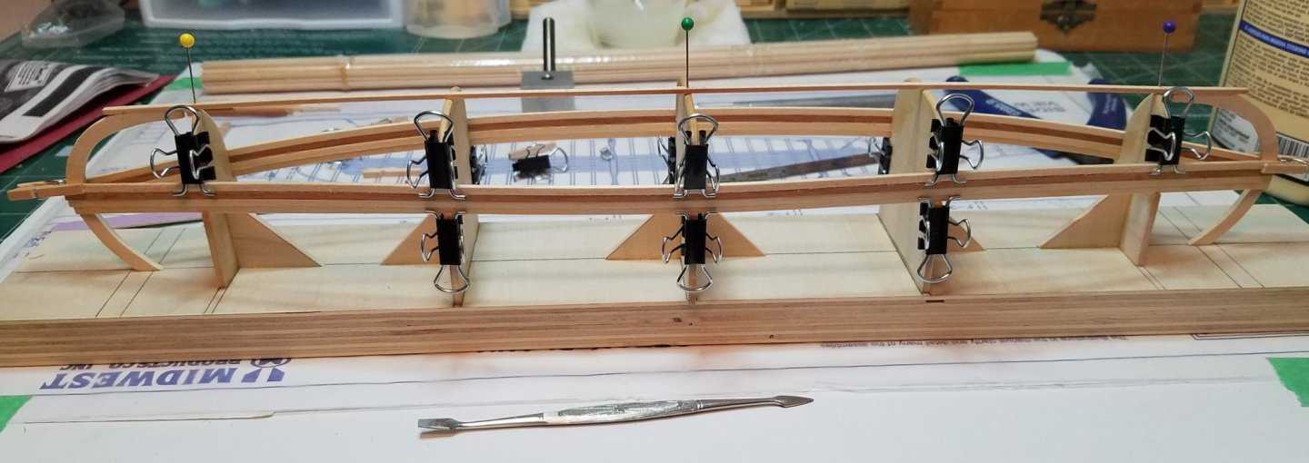
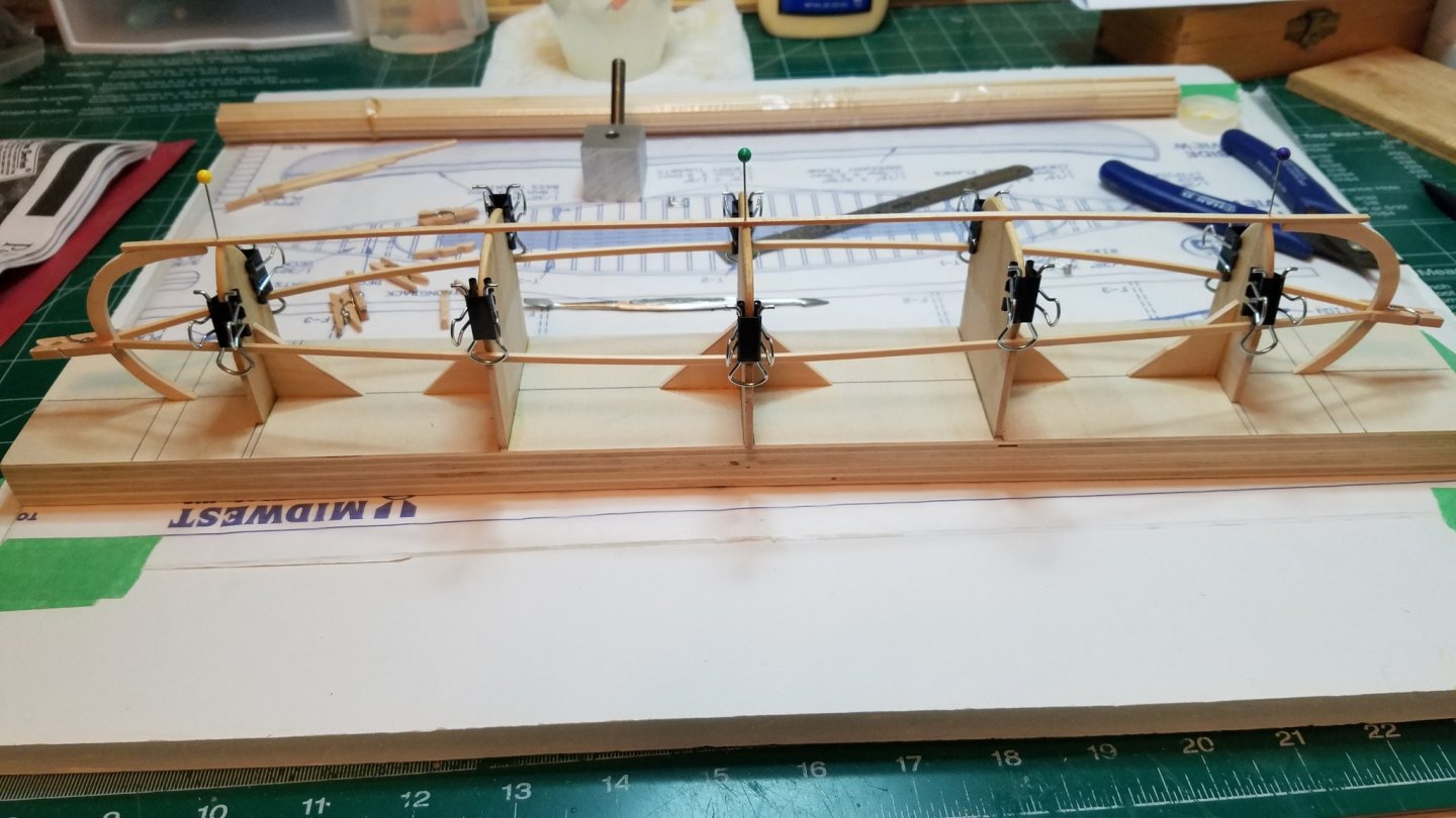
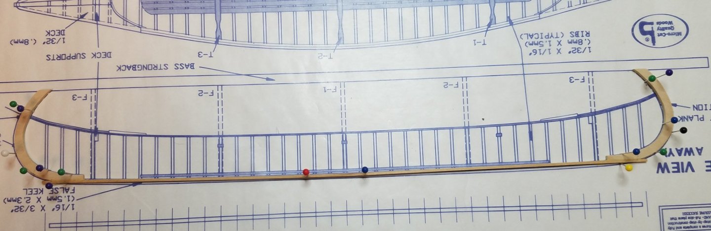
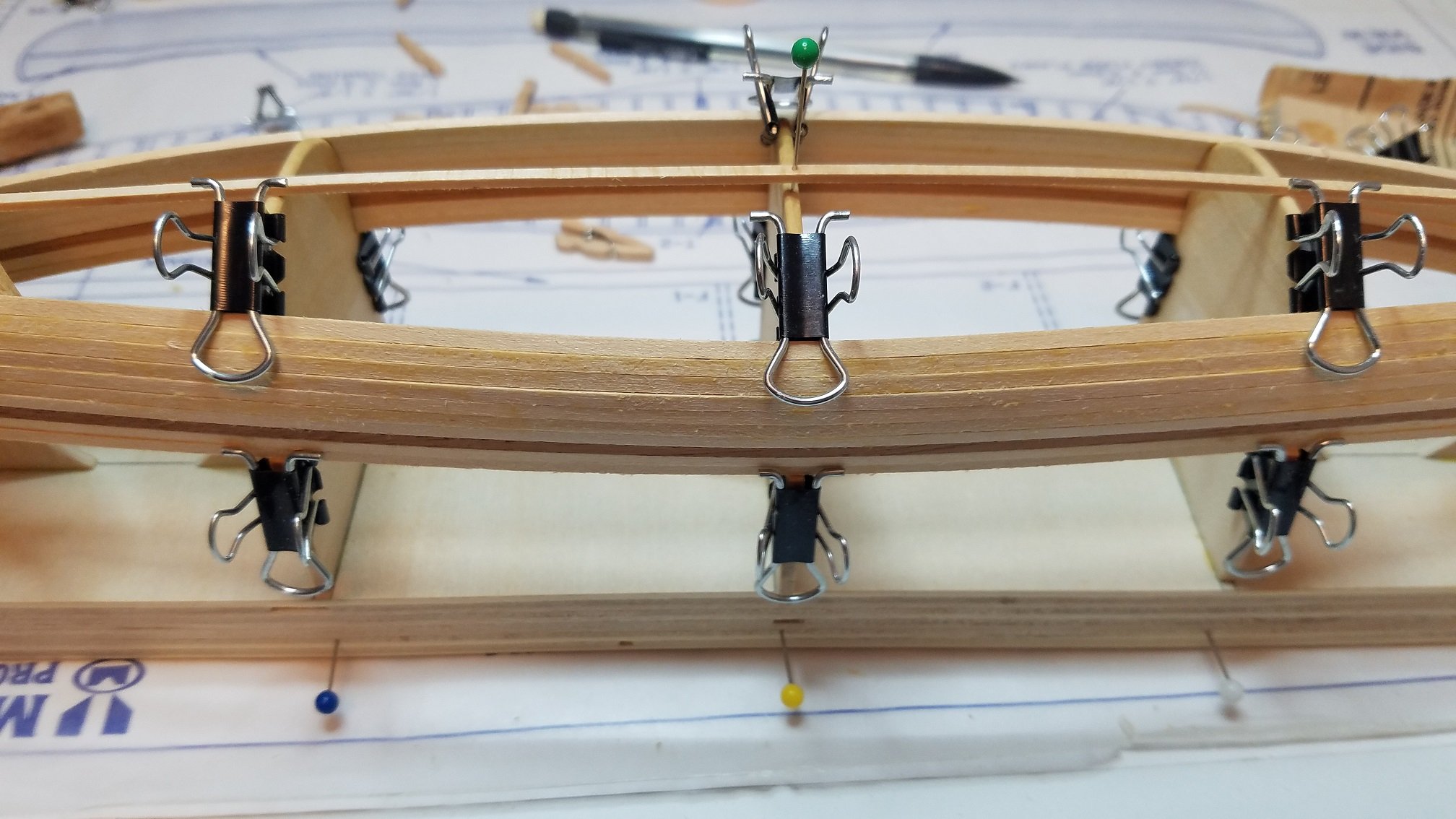
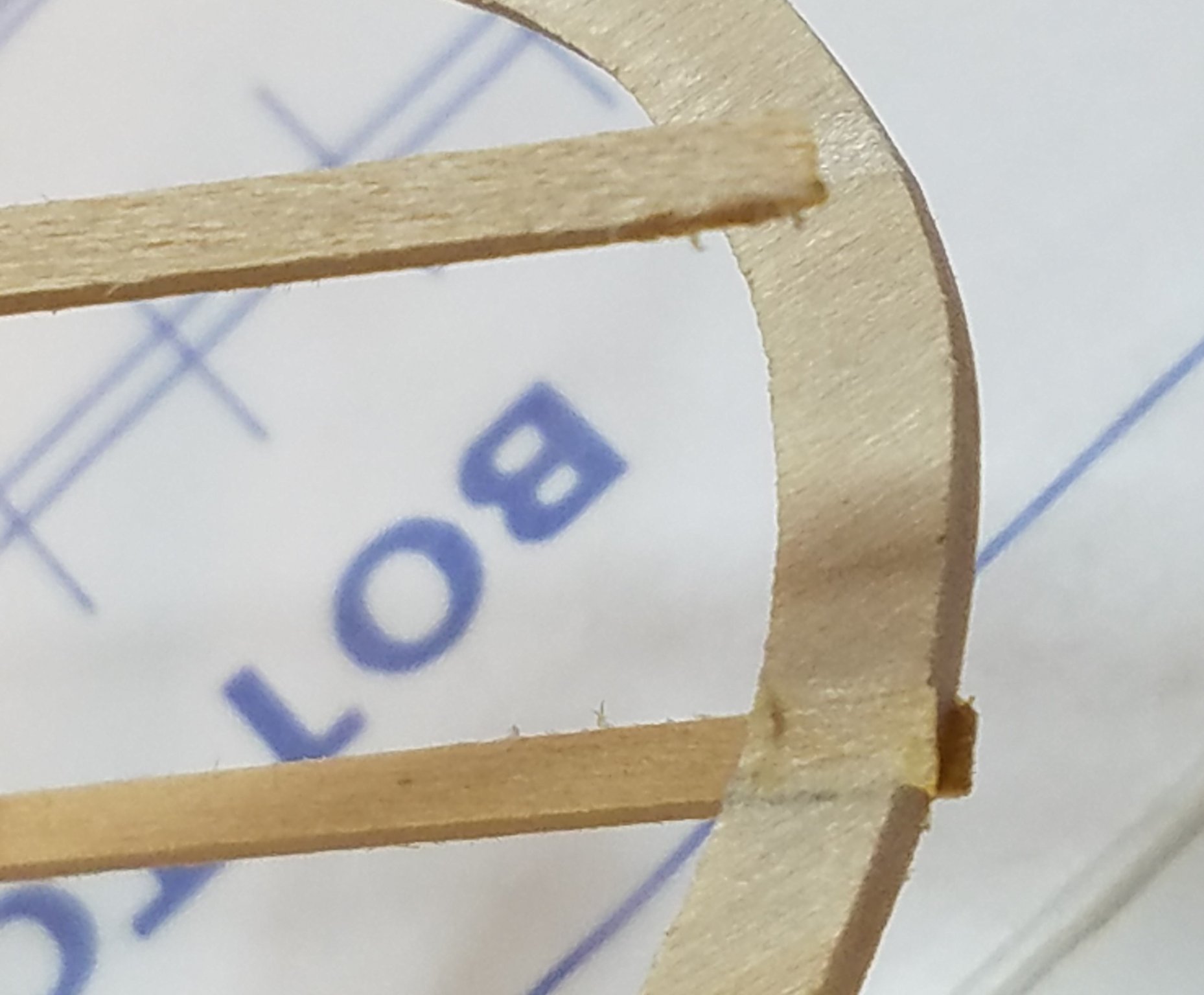
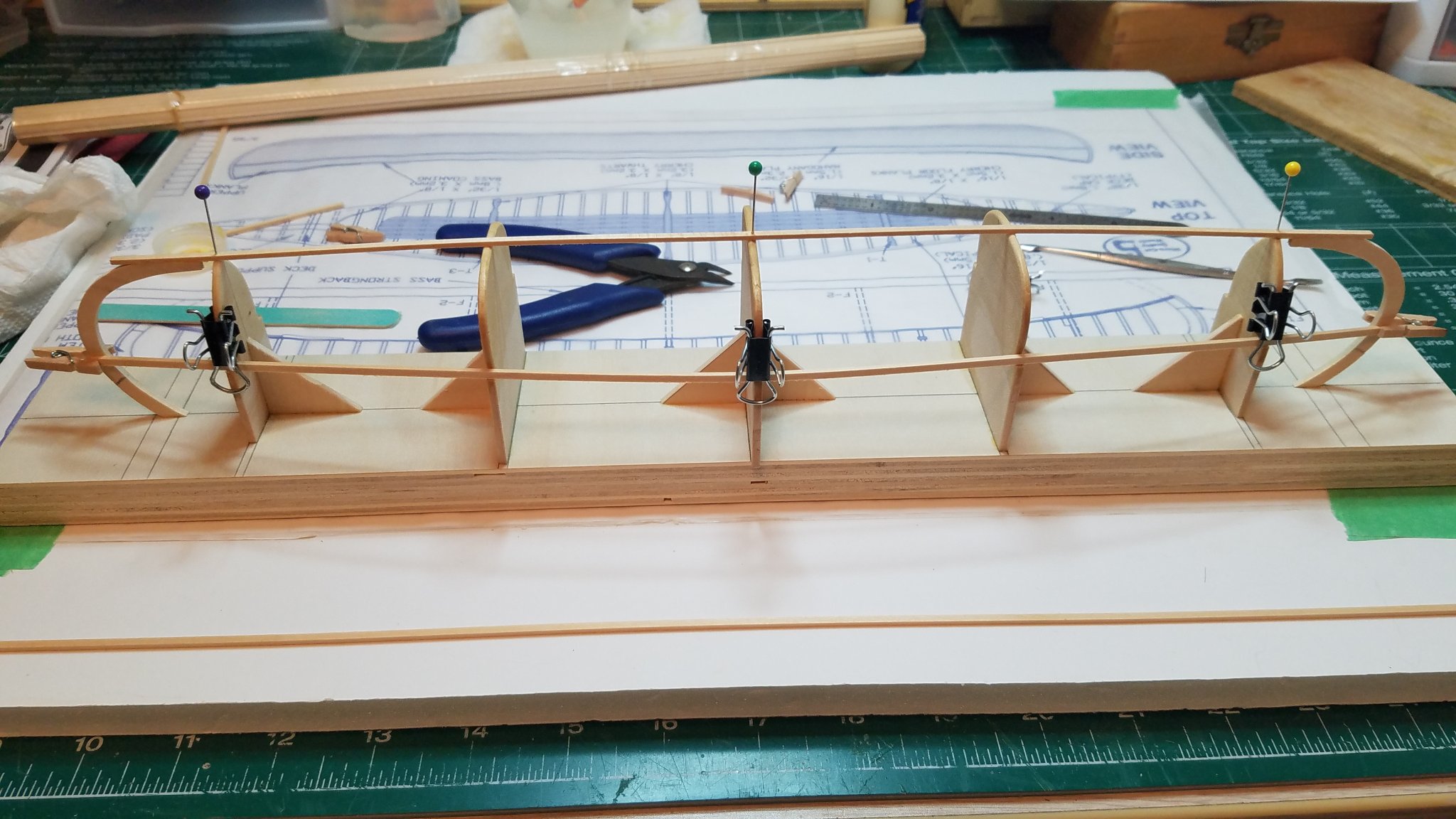
Thanks for all the likes. And the planking continues. I told the admiral I will be self quarantining in my hobby room until the crisis passes or I am done planking which ever comes first. I think the corona virus will be long gone before I am done planking this thing. Slow and steady. I am using PVA exclusively on this build which means I have to wait 15-20 mins between each plank so it will take a while. I am running out of clamping room on the outer frames so I will be switching over to a combination of clamps and rubber bands for the duration of the planking. That is the reason for the pins on both sides of the base. I will also need to start beveling the planks that go around the "bilge turn". I really should have beveled the last one in the picture, if you look close you can see a small gap due to the turn starting on the center frame. That's it for now. Stay safe everyone. Regards
- 84 replies
-
- 7
-
-
- peterboro canoe
- Finished
- (and 1 more)
-
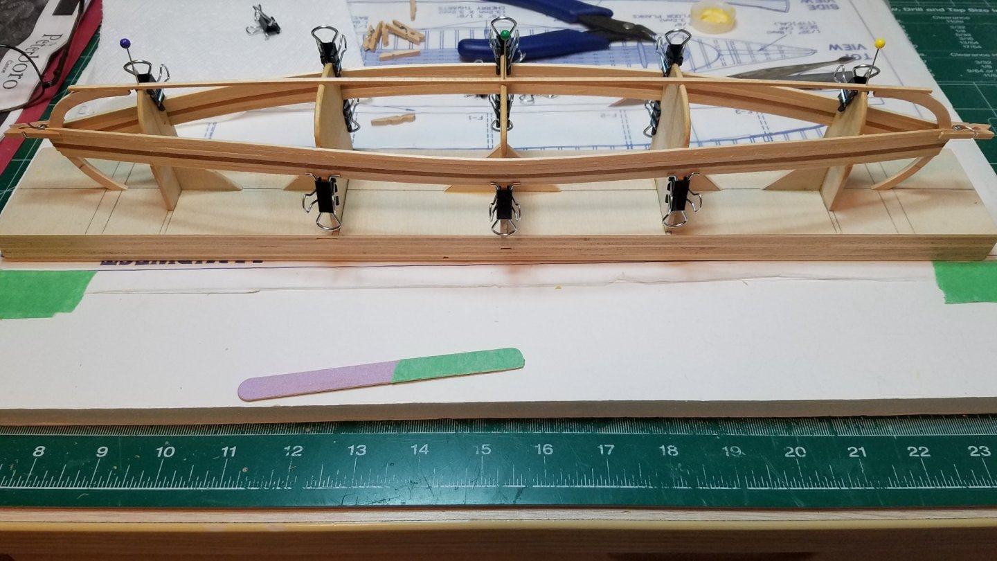
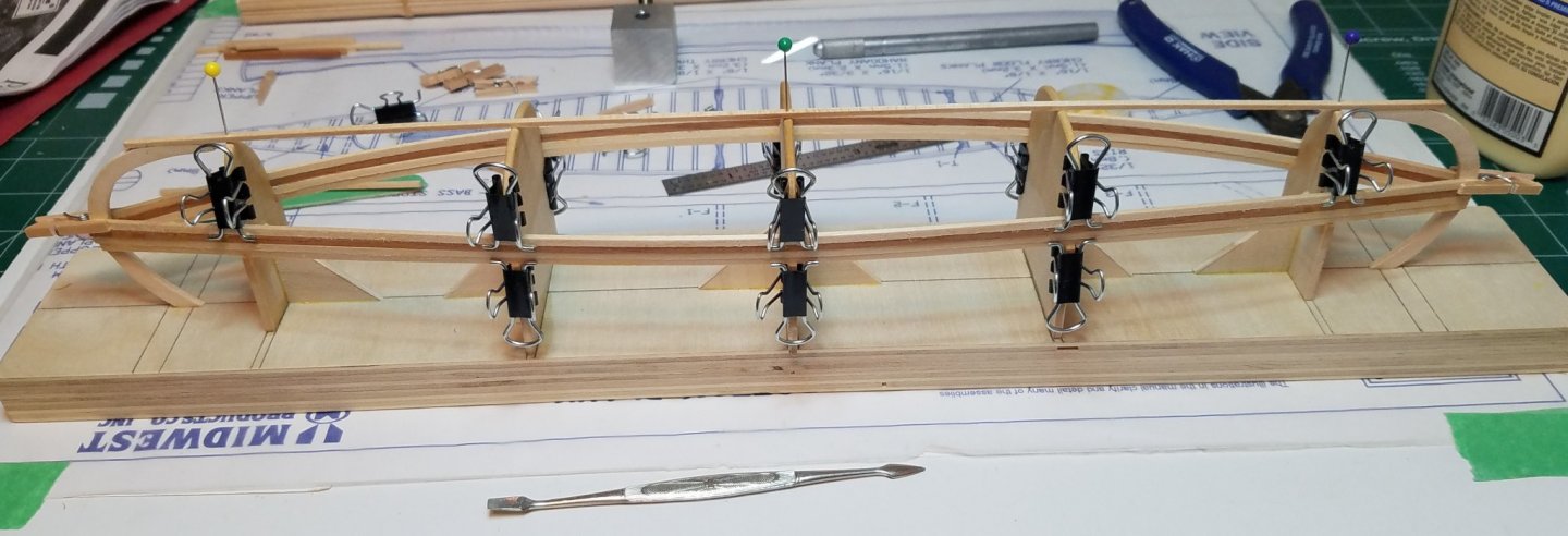
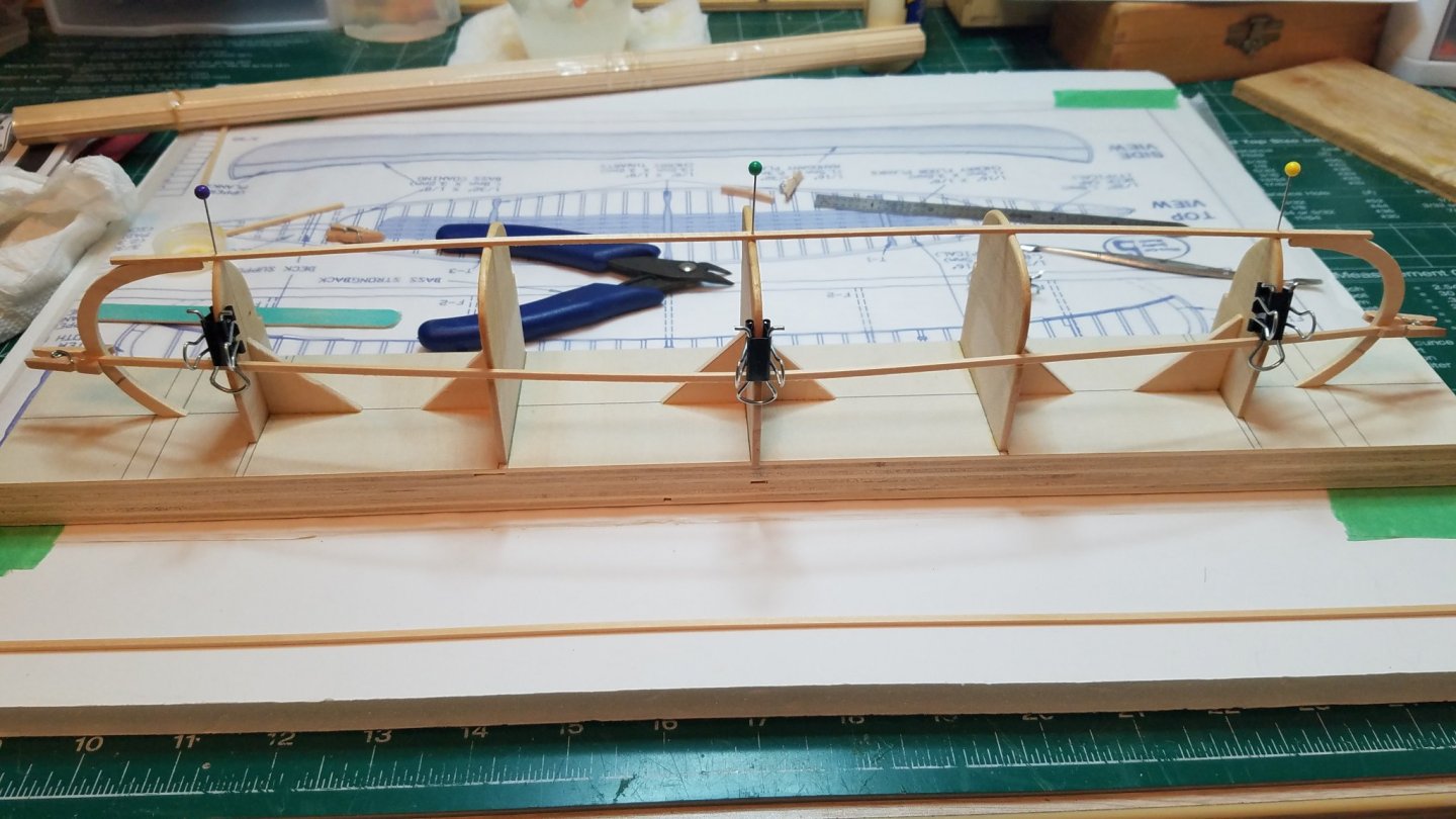
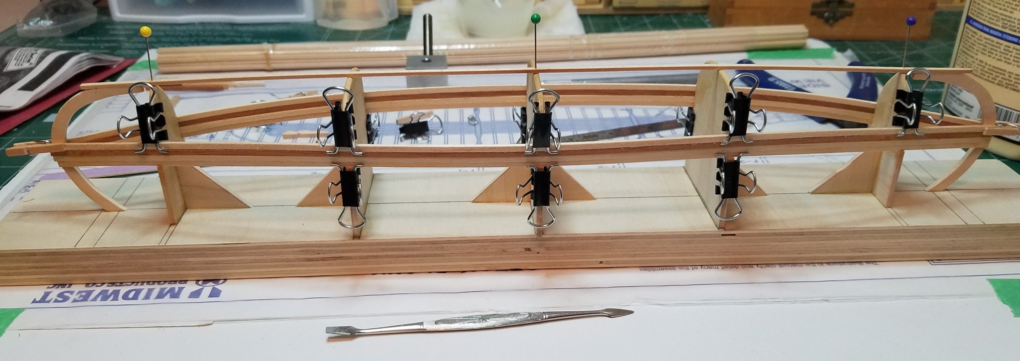
Just a brief update tonight. Before I went to bed last night I noticed that one of the first planks was not sitting tightly against all of the forms. I did not take a picture but it was off of both of the F2 frames by about 1/8". So after laying in bed thinking about it for a couple of hours, at about 1:30 this morning had to get up and fix it. I simply took a kerf cut worth of material away when I cut it. Then cleaned up both sides of the cut. Clamped and re-glued it and that was all it took. So I went back to bed and slept like a baby. Today the planking continues. The gunnel has a distinct inward turn at the top at frames F2-F3-F2. I added the three clamps along this edge to keep the top of the plank firmly pressed into this part of the frames. I will leave them there until the planking is complete. Not more than a week or so at the rate I am going. Well better get back to it. I can get 2 or 3 more before bed time. Regards


- 84 replies
-
- 7
-
-
- peterboro canoe
- Finished
- (and 1 more)
-
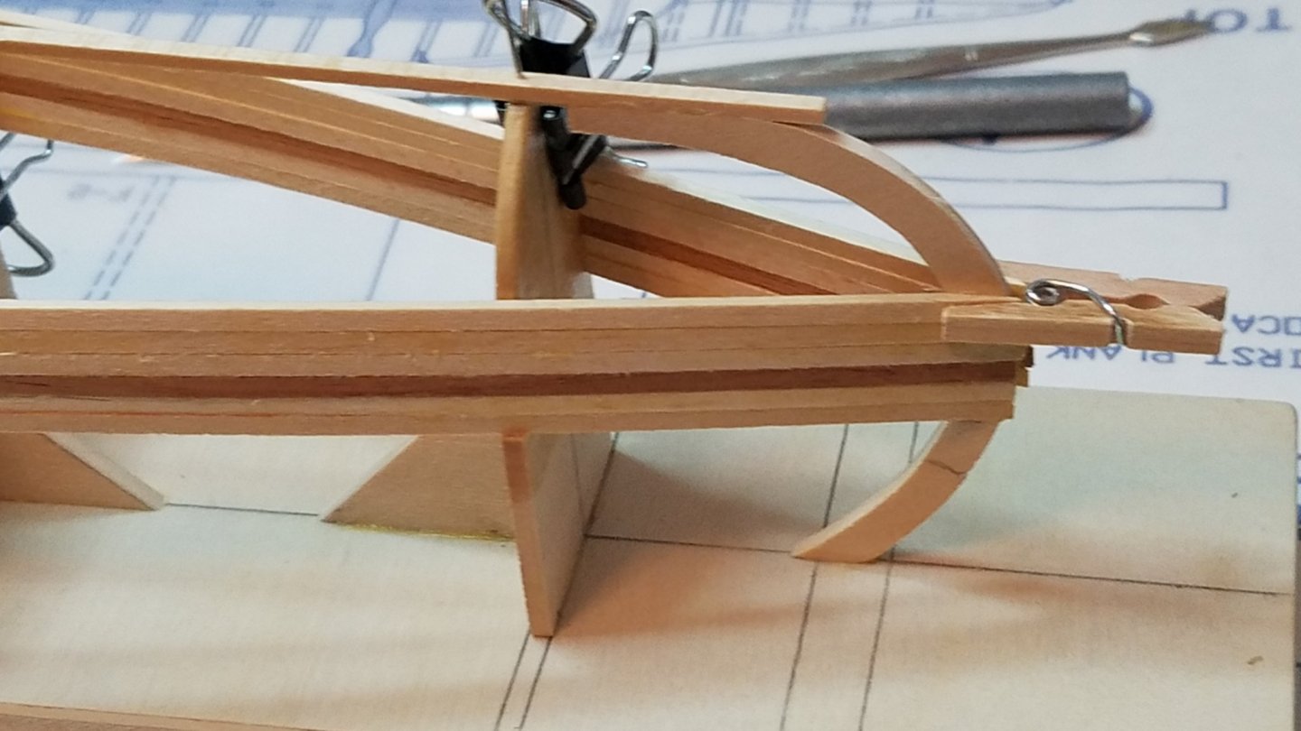
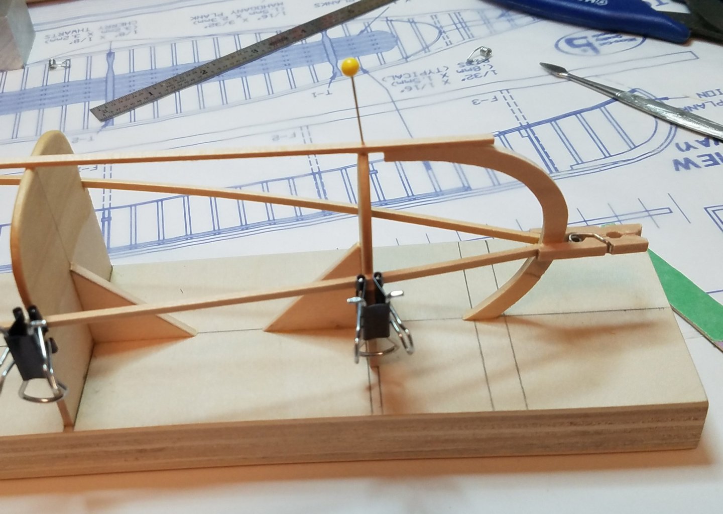
When I got home from work this evening I put a couple coats of wipe on poly on the areas of the frames that will be in contact with the planking in the hopes of minimizing gluing between the two. Once that was good and dry I mounted the keel assembly to the frames and base board. Then the first plank was cut beveled and glued up. Then its opposite member. I knew those dollar store toy cloths pins would come in handy some day. I think I will let that set up for awhile before proceeding any further tonight. Regards
- 84 replies
-
- 9
-
-
- peterboro canoe
- Finished
- (and 1 more)
-
Congrats!! and Welcome Back!!
-
I am currently building the Midwest Peterboro Canoe. I want to make sure that the finished hull comes off of the frames cleanly. I was thinking of giving the frames a coat or two of wipe on poly prior to starting the assembly. I will be using PVA ( Titebond ) will the poly prevent the glue from adhering to the frames? Or is there a better more proven method? Or am I just over thinking it as I usually do?
-
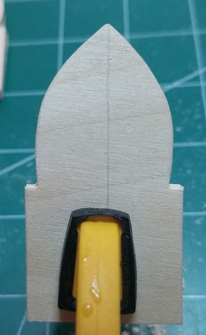
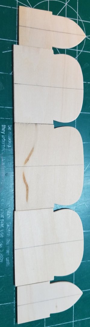
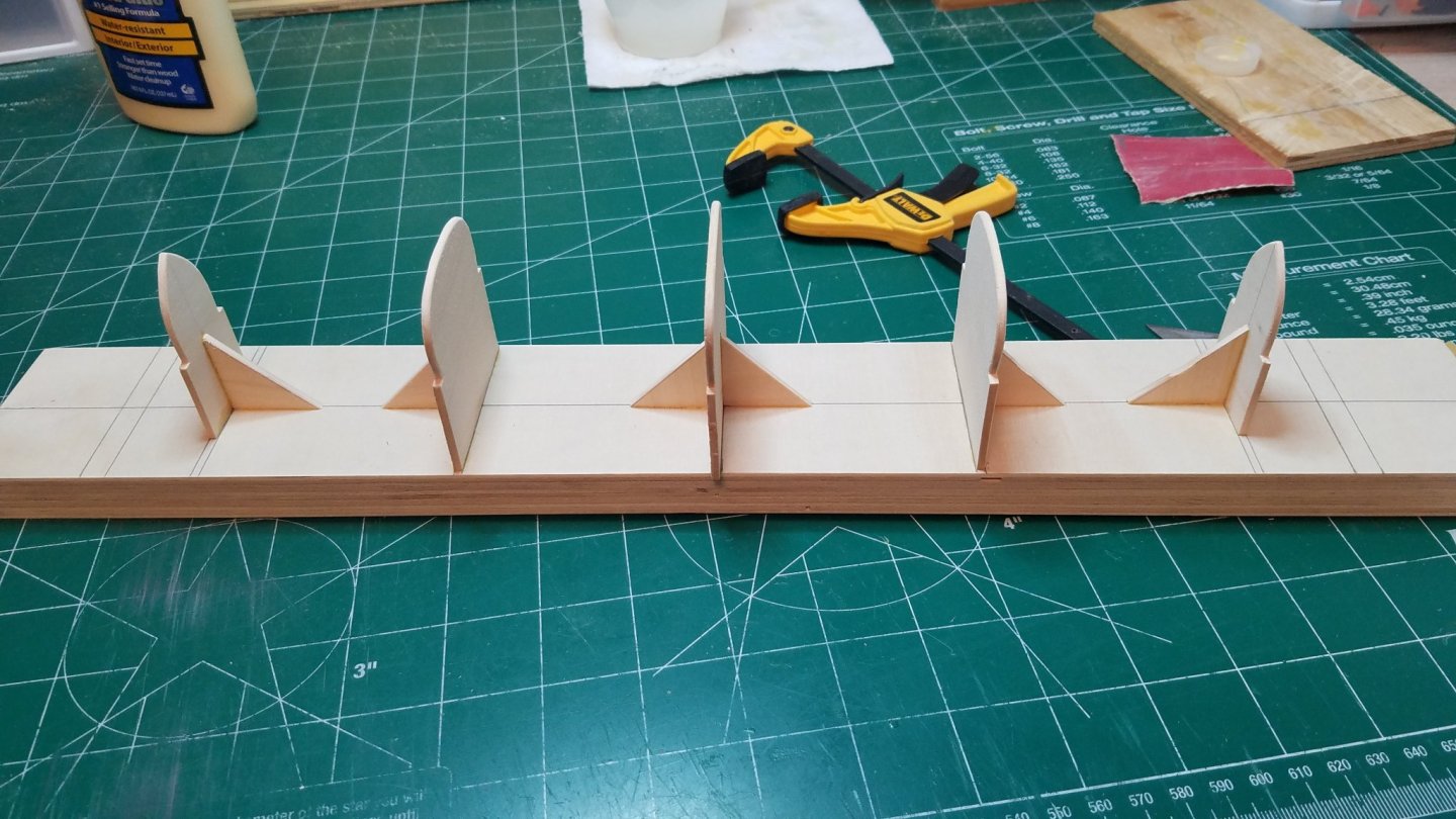
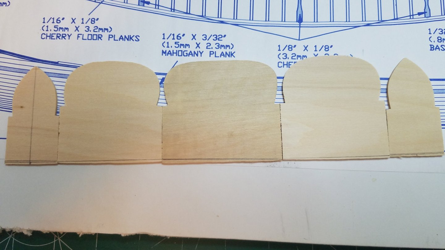
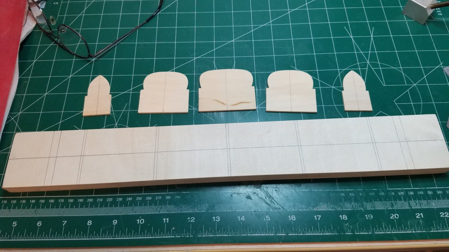
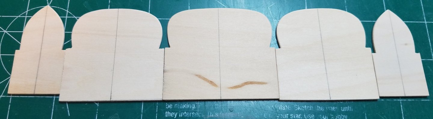
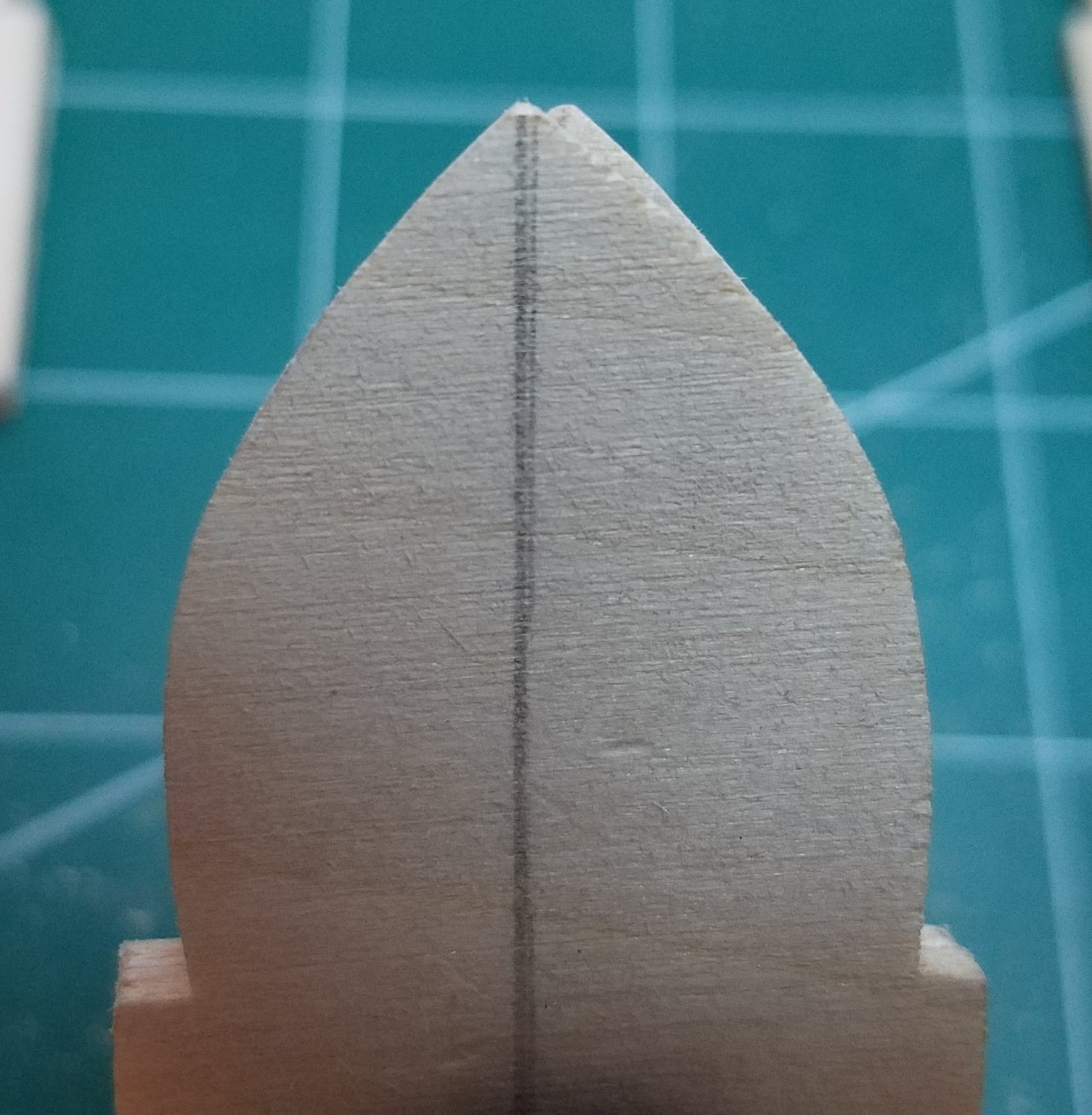
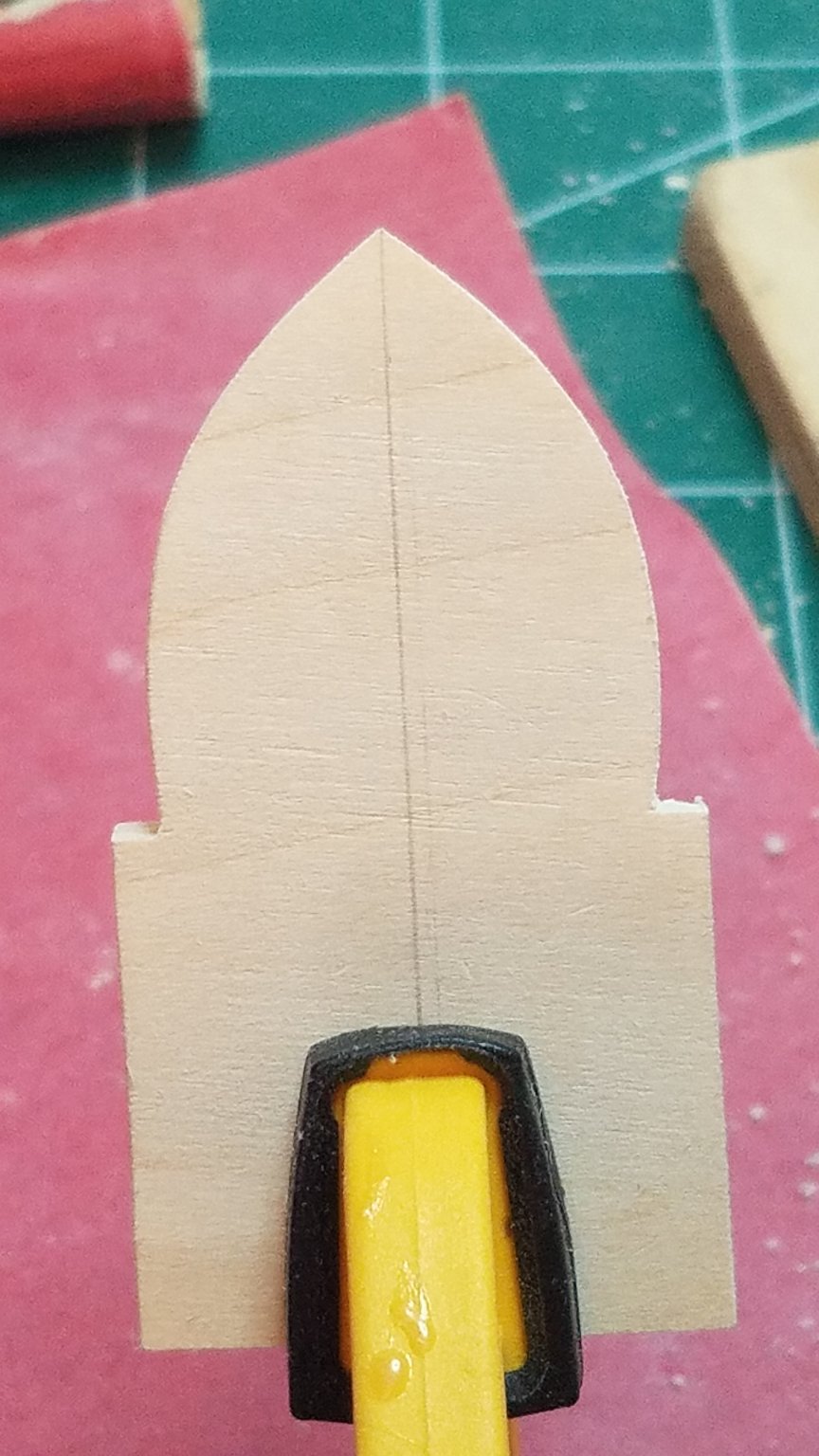
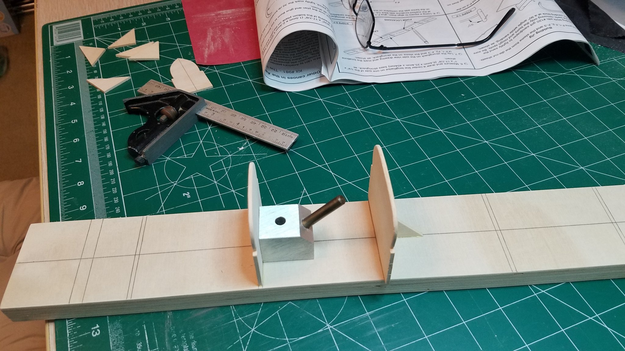
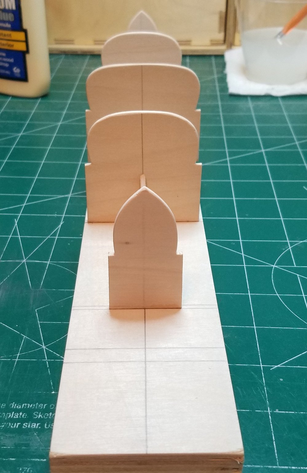
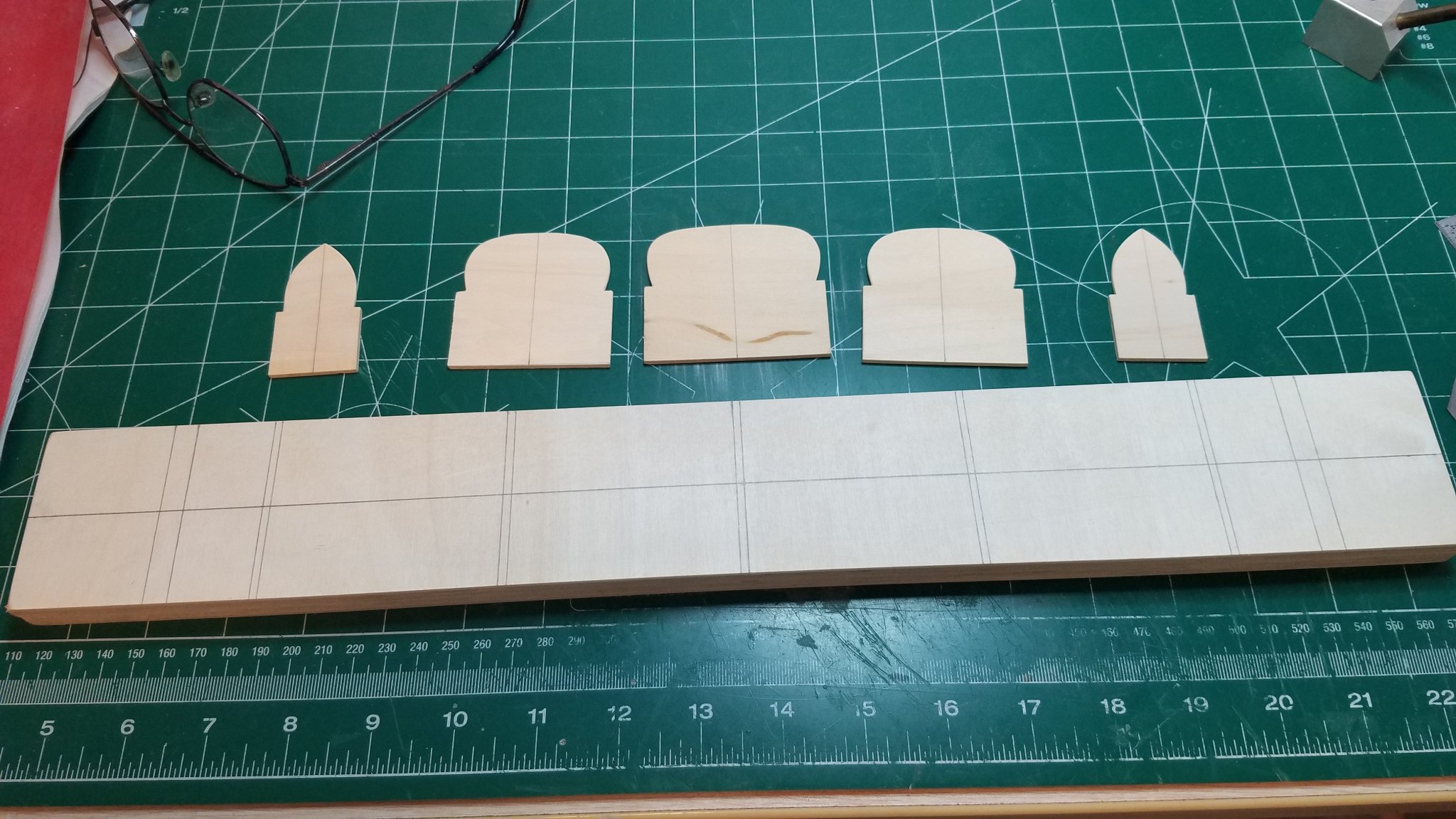
Thanks for the likes and the comments. Well several minor and correctable things about this kit slowed me down tonight. The dies were obviously not what they once were by the time this kit was made. All of the die cut sheet parts have a terrible bevel on them. Also none of the parts are symmetrical. I know big deal it is just a canoe and only cost me $19.50 after all. But here is the thing. I am a design engineer by day. I design piping and control systems for water treatment systems. Most of my day is spent staring at a computer screen drawing and looking at perfectly parallel and perpendicular lines. Also by design most piping components are symmetrical. So I can tell from across the room if two lines are square or parallel or if a shape is symmetrical. These things just jump right out at me. And if they should be but are not it really drives me nuts beyond description. Call it anal retentive or OCD or what ever. I cannot just let it go. Having said all that on with the show as they say. My quick fix of the warped frames seems to have worked pretty well. To start with here is my new building base to replace the warp one that came with the kit. 3/4" Birch grade A ply. So far so good. I started by just checking how square the parts were as you can see by the reference lines they are not at all. Then I drew the center lines using the plan as a template this is where the odd shape really jumped out at me. This is both F3 frames one on top of the other. they align perfectly but you can see they are lopsided. However flip the top one over and bam! So using a sanding block I removed the excess material from first the top piece then switched to the bottom one. Then I redrew the center line. Not perfect but a lot better. The pair of F2 Frames were also the same but not quite as bad. Here they are with new center lines and nice square bottoms. Then I laid out the building base as instructed. Using my small square and this little block I found in a box of tools I purchased a couple of years ago started installing the frames on the base. The gussets were just cut from the corners of the die cut sheets. Over kill I know but I would refer you to the top of this post. I also eased the edges of the frames where the planking lays to limit the surface area in contact with the glued up planks. Then I laid out the stem pieces on the plan these also required quite a bit of reshaping. Well that is it for tonight. I know I created more work than I really needed to but that's what I do. Gotta go now the panthers are playing. Don't know why this extra pic is down here I have tried several times to edit and delete it but it will not go away.


- 84 replies
-
- 8
-
-
- peterboro canoe
- Finished
- (and 1 more)
-
VAC-U-DUCK - Vac-U-Boat by Osmosis - FINISHED
Osmosis replied to Osmosis's topic in Non-ship/categorised builds
Since it is a Drake I did not want to call it a maiden voyage..... but then again it is 2020. -
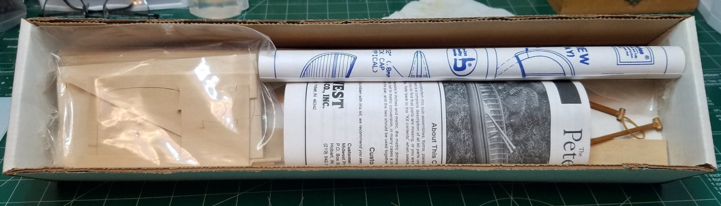
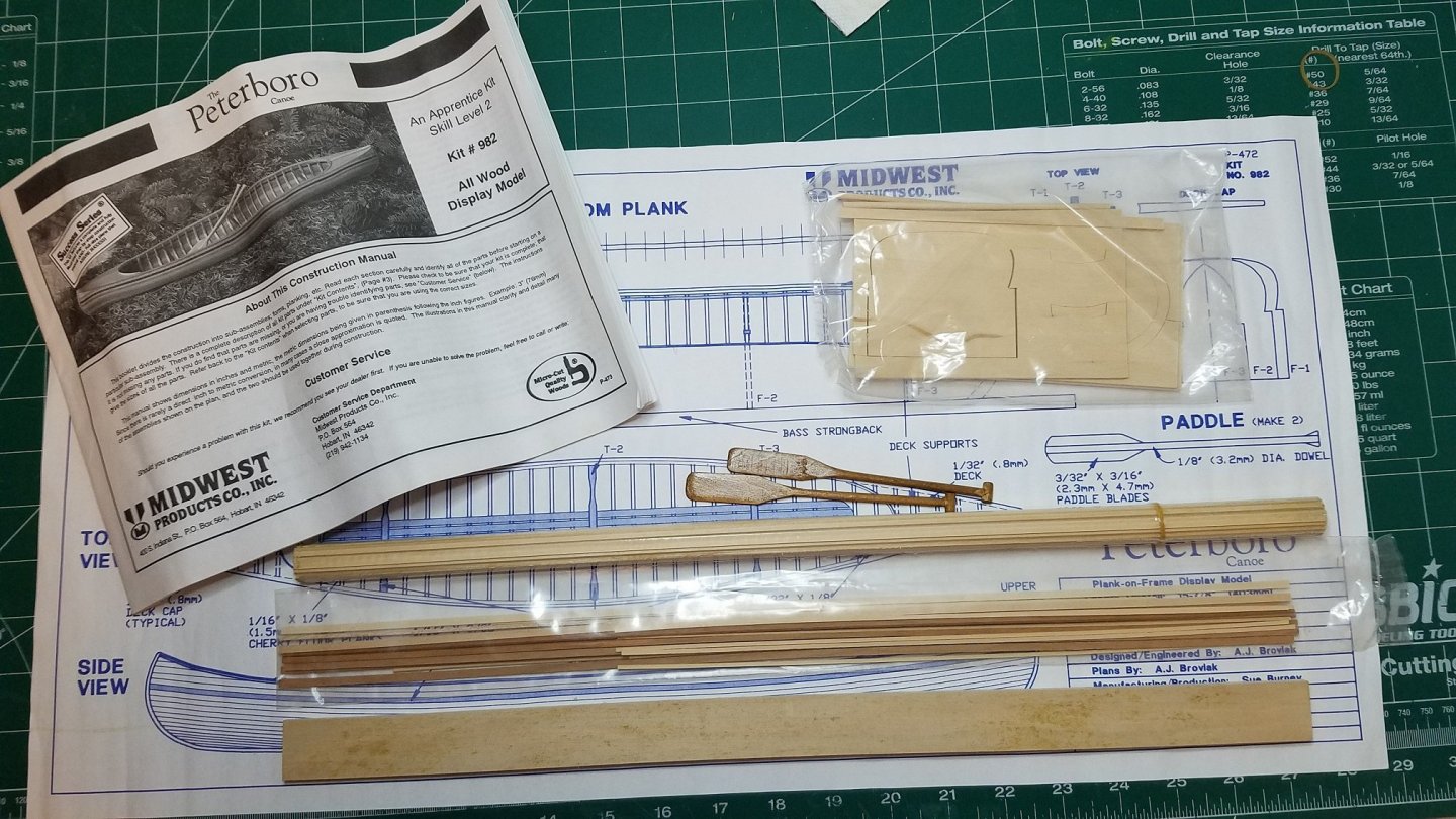
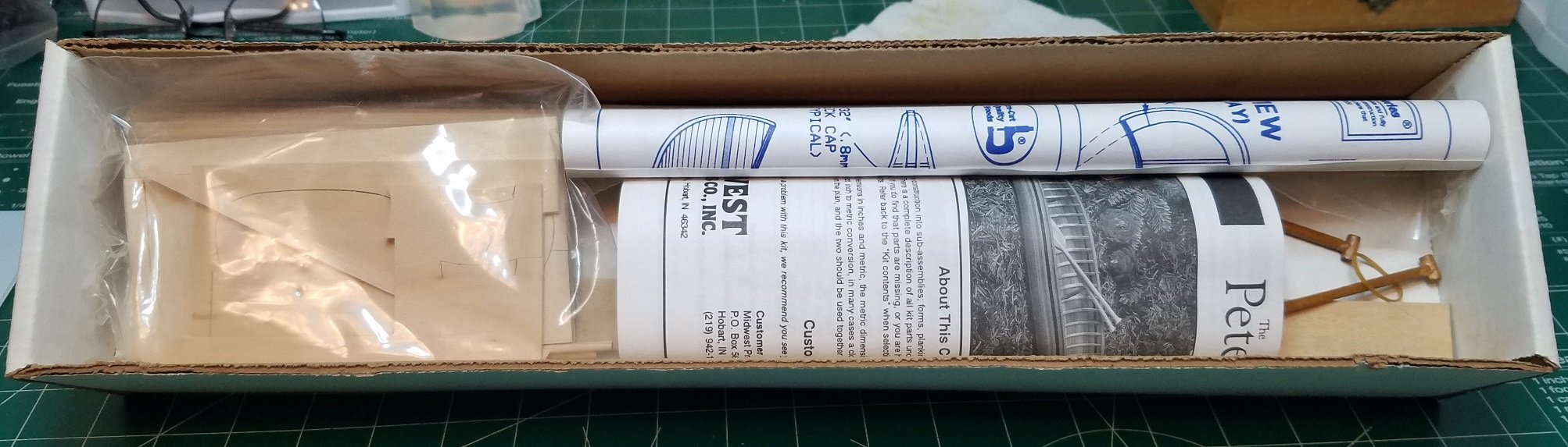
This is a kit I have wanted to try for a long time. I was inspired to finally go out and find one by member Duanelaker's recent build. I got this one on e-bay for $19.50 plus shipping. I hope I can do it justice. The box shows a little water staining but the contents were dry and did not at first appear to have been wet. All of the parts were in their unopened original packaging. An inventory confirmed all of the parts were there, including two pre-made and finished paddles plus the parts required to make two more. As you can see there is some discoloration (mildew) on the "strongback" building base. Upon closer inspection you can see that it is warped to the point of rendering it unusable. This will be easily replaced by a nice stable strip of 3/4" marine plywood. Two of the building forms were slightly warped also. So I soaked them for a couple of minutes and clamped them between a couple of strong backs for the night. Hopefully I will be able to get started in earnest tomorrow night. Best Regards
.thumb.jpg.763407220106385b0451a417914da63f.jpg)
- 84 replies
-
- 5
-
-
- peterboro canoe
- Finished
- (and 1 more)
-
VAC-U-DUCK - Vac-U-Boat by Osmosis - FINISHED
Osmosis replied to Osmosis's topic in Non-ship/categorised builds
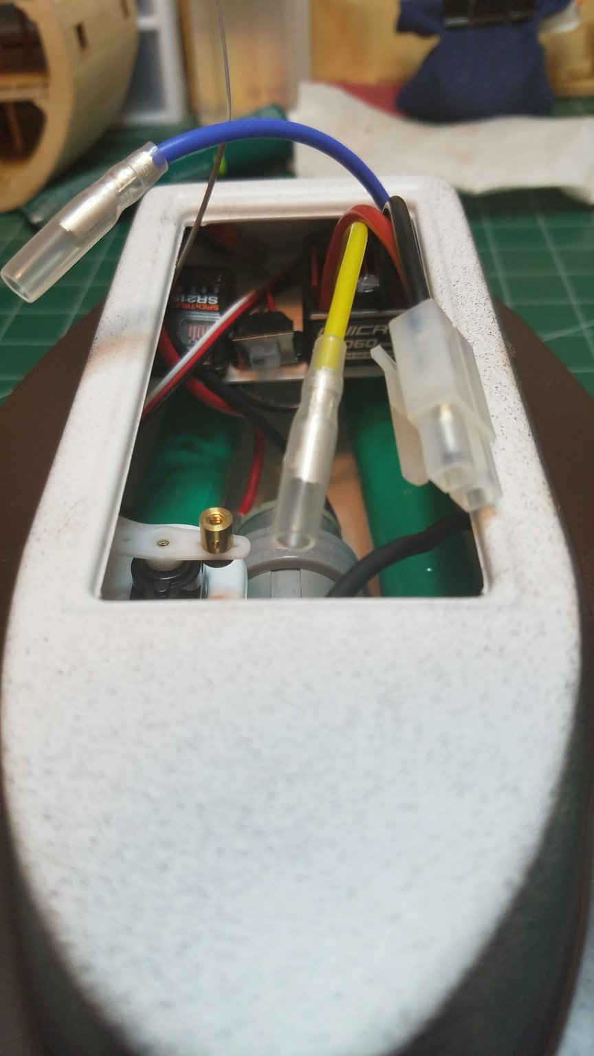
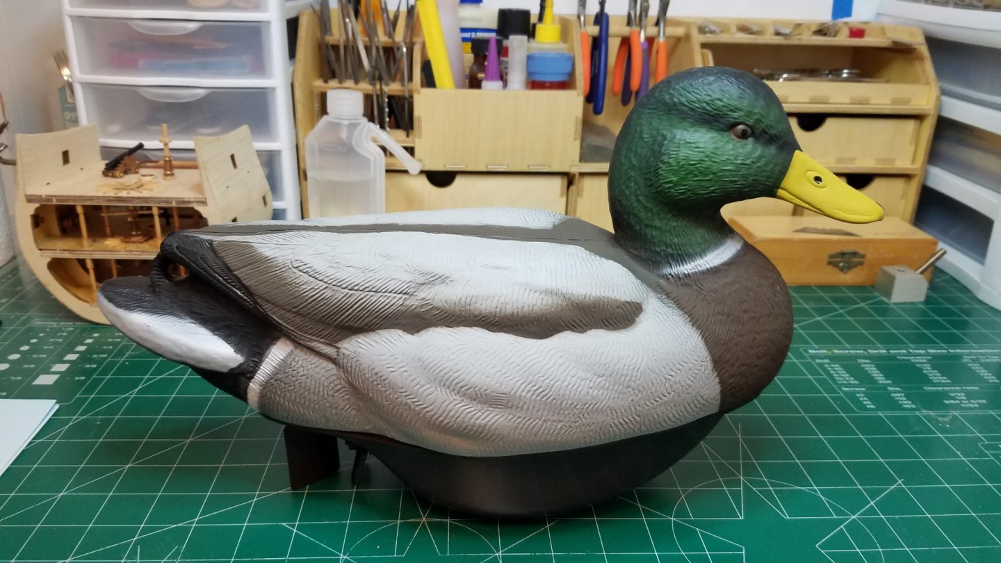
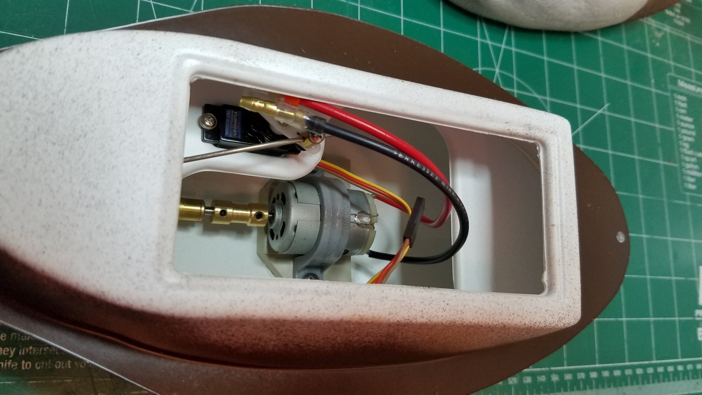
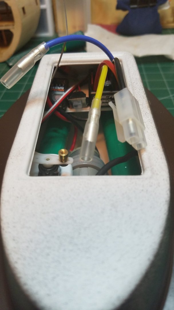
Just a small update. All of the innards are in and tested. Batteries are fully charged. The clear acrylic hatch needed to have the corners rounded slightly in order to seat in the recess fully. The ESC power switch did not have a means of through mounting so I filed a small notch in the hatch so I could have access to it. I will finish taping the hatch prior to going to the pond. Here he is ready and waiting for his first swim. Now if only the weather would cooperate! It was blowing 18-20 yesterday and more of the same is predicted for today. When I let the dogs out this morning it was blowing pretty good so we will see. Maybe it will lay down enough by this evening to get him wet. Regards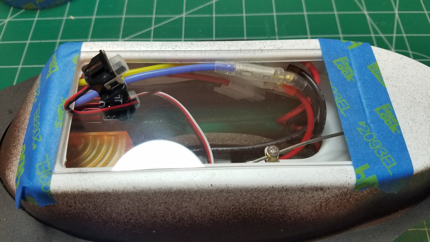
- 36 replies
-
- 12
-
-
kit review USS Missouri (or any Iowa class) 1/350 by Joy Yard
Osmosis replied to Tigerdvr's topic in REVIEWS: Model kits
I saw that but something about those listings seemed off. I don't know what but something said don't click here. -
kit review USS Missouri (or any Iowa class) 1/350 by Joy Yard
Osmosis replied to Tigerdvr's topic in REVIEWS: Model kits
Just in case I should work up the courage to try something like this one day could you tell us where you got it it. I looked through joy-yards web site and could not find any pricing or ordering info. Thanks -
kit review USS Missouri (or any Iowa class) 1/350 by Joy Yard
Osmosis replied to Tigerdvr's topic in REVIEWS: Model kits
I wish I had the skill set required to do justice to one of these. I will be following this build with envy when you get started. -
Fortunately I live and work close enough that if I really need something I can make the trip down there and back in a slightly extended lunch hour.
-
VAC-U-DUCK - Vac-U-Boat by Osmosis - FINISHED
Osmosis replied to Osmosis's topic in Non-ship/categorised builds
Imagna, Thanks for the info I will remove the silicon as soon as I get home tonight. My RC interest actually started with helicopters. From helis I slowly started to acquire airplanes but as with most hobbies life seemed to intrude and I slowly got rid of all of my planes helis and gear. Thankfully I was able to get a good value for all of it as FM was still the preferred radio. If I had waited another couple of years I would probably never been able to get rid of it. Once my Daughter was grown up and married and I got to the point where I could take up hobbies again I decided yachting was now my speed and since I have a nice pond right across the street it is very easy to grab a boat and set sail. -
VAC-U-DUCK - Vac-U-Boat by Osmosis - FINISHED
Osmosis replied to Osmosis's topic in Non-ship/categorised builds
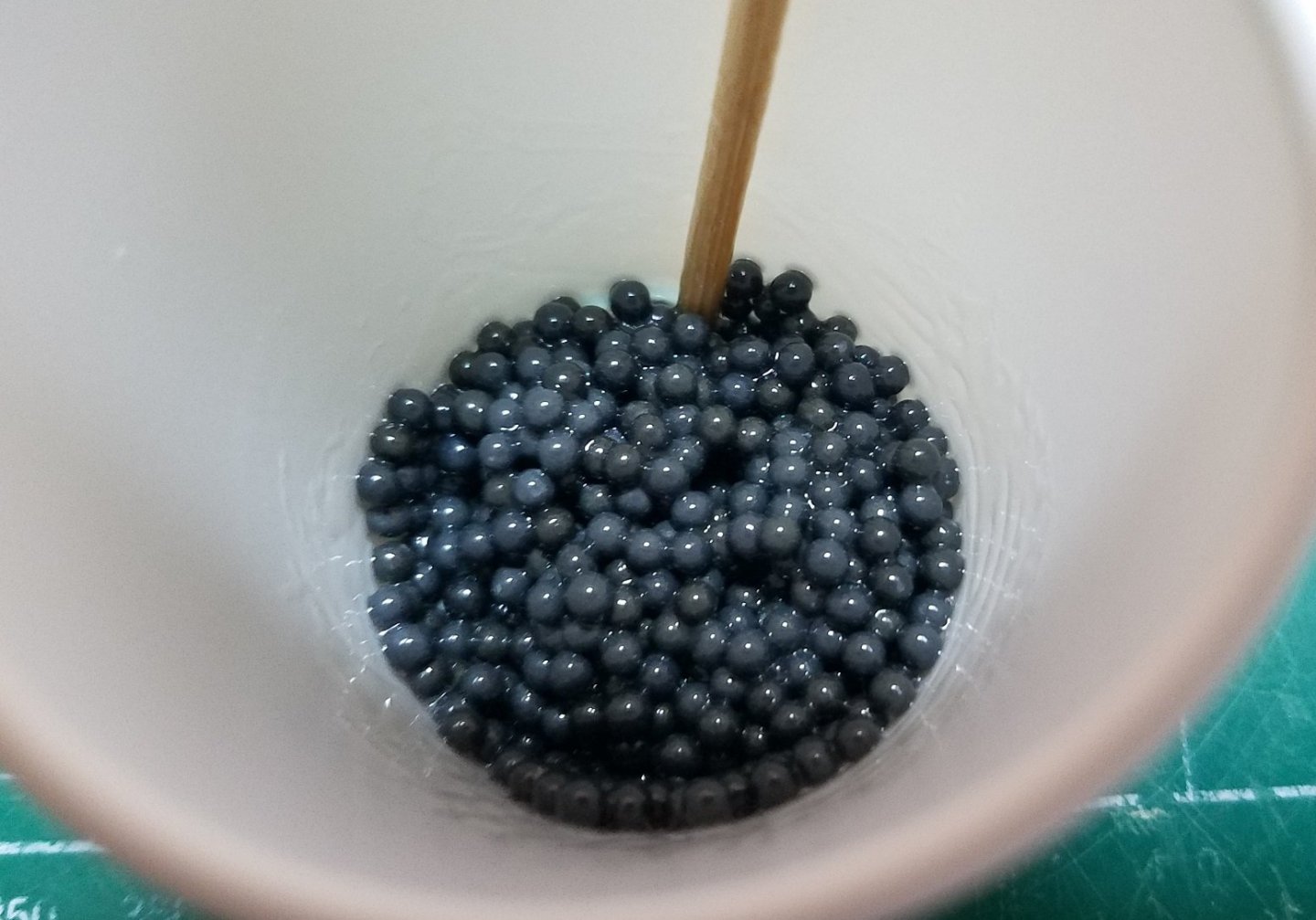
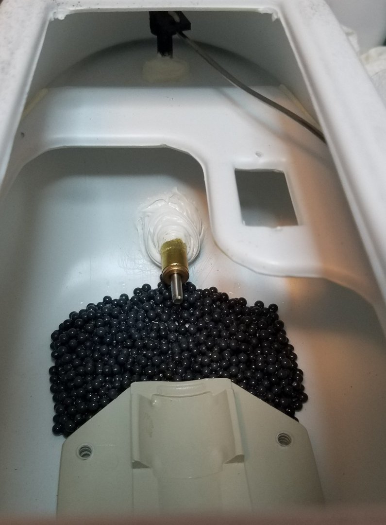
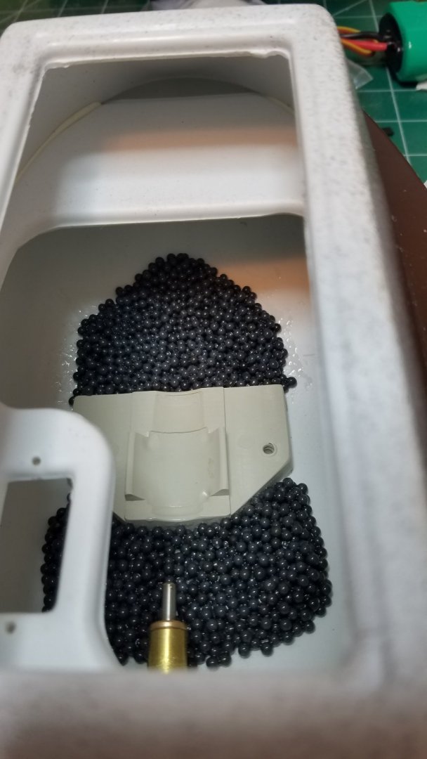
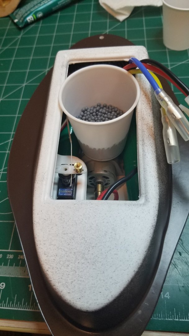
Thanks for all the comments and the likes. Some updates on my progress over the last couple of evenings. First I finished the battery mod. By covering the exposed ends with a dollop of silicone sealant. I also connected bound and tested all the radio gear so that it is ready to go when the time comes. Then I cut a gasket from some closed cell foam I had left over from another project. Then it was time to install the ballast. I divided it up roughly in half. Then divided one bag in half again. and placed it in the bilge. As usual if I think about it long enough I will finally decide to do it the right way. I was going to leave the ballast "loose" (in zip-loc bags and attached with velcro ) so as to be adjustable. But with so little room and limited access once the batteries are in place I decided to make most of it permanent. So after once again removing everything. I mixed up a little 30 minute epoxy. Added slightly less than half of the lead shot and mixed well. Then using a tongue depressor as a scoop carefully placed it in the aft bilge. Then lather rinse and repeat for the forward bilge. I kept about 1/4 of the shot for final adjustment. Once the epoxy is set I will reinstall everything and that should be about a wrap except for getting it over to the pond. I will let you know how that goes in the next installment. Best Regards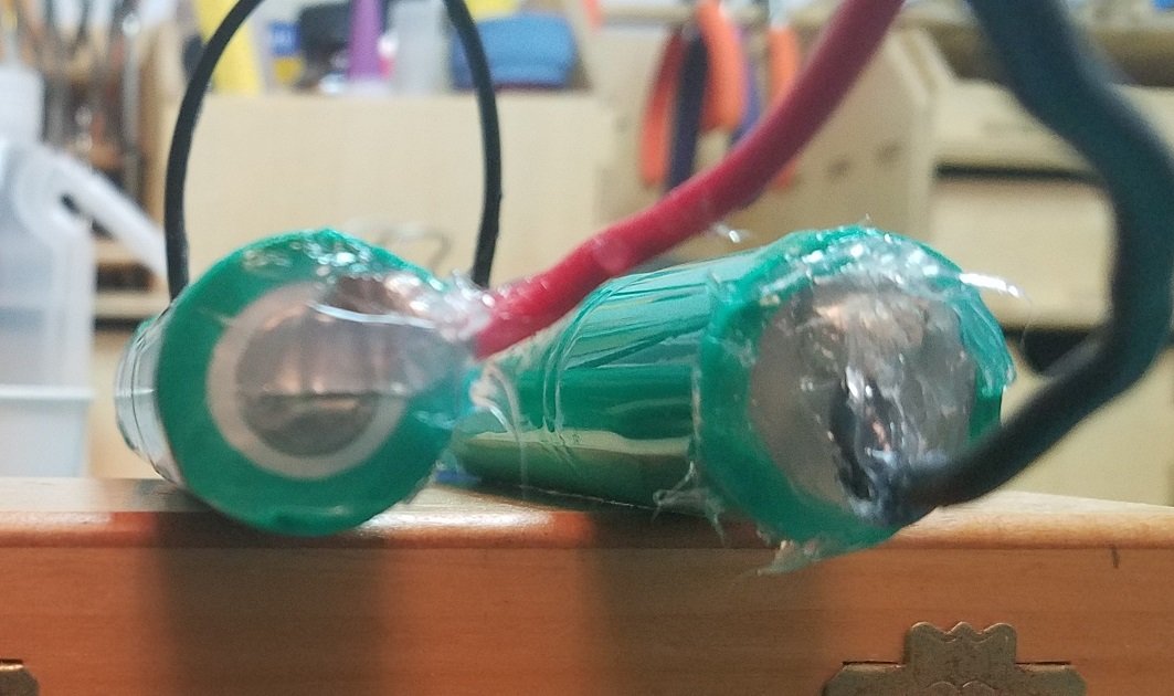
.thumb.jpg.4eed6493f2f31c2feda2f84e45e1c24a.jpg)

.thumb.jpg.e91d4db090fd4319eac7d8696b901817.jpg)

-
VAC-U-DUCK - Vac-U-Boat by Osmosis - FINISHED
Osmosis replied to Osmosis's topic in Non-ship/categorised builds
If there was a little more room I was thinking if installing a pump and hose (water cannon) through the "bill". Maybe later but for now I don't think he will be seen as much of a threat. -
VAC-U-DUCK - Vac-U-Boat by Osmosis - FINISHED
Osmosis replied to Osmosis's topic in Non-ship/categorised builds
Here in FL, we have mostly Muscovy Ducks and Egyptian Geese which are quite a bit larger and more aggressive than wild ones. Mostly due to people feeding them, they have lost all fear of humans. I am a little worried but I hope to be able to out run them. I did do a little bit tonight but mostly just trying different locations and amounts of ballast. I should have this done tomorrow and in the pond this weekend. I will post update and pics tomorrow night. Regards -
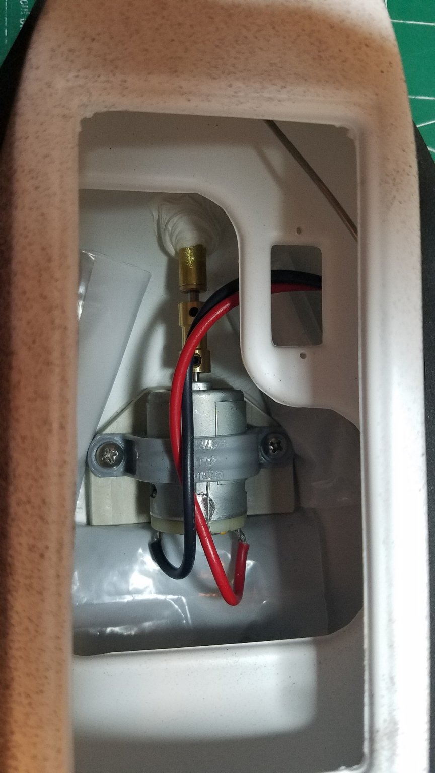
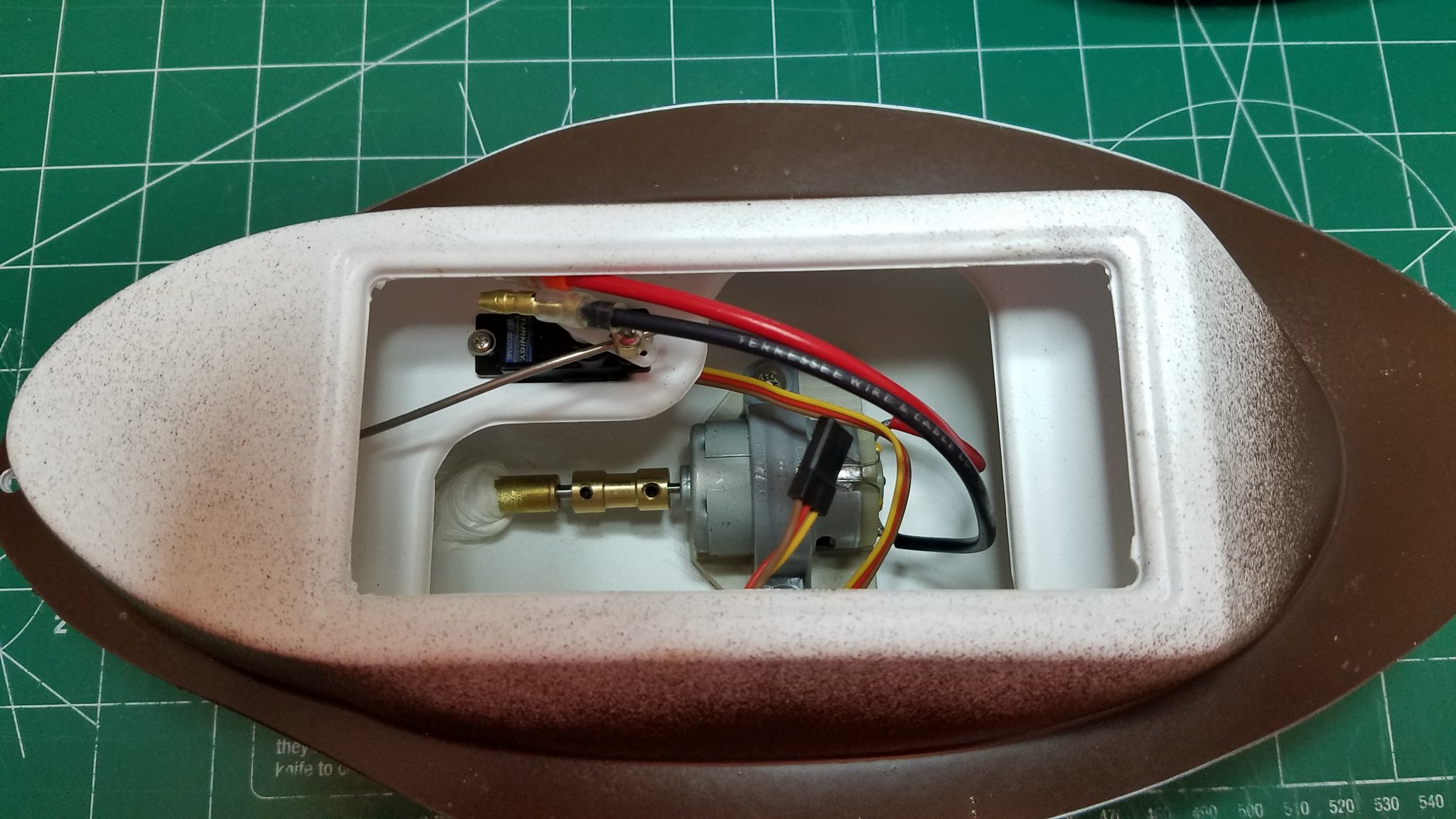
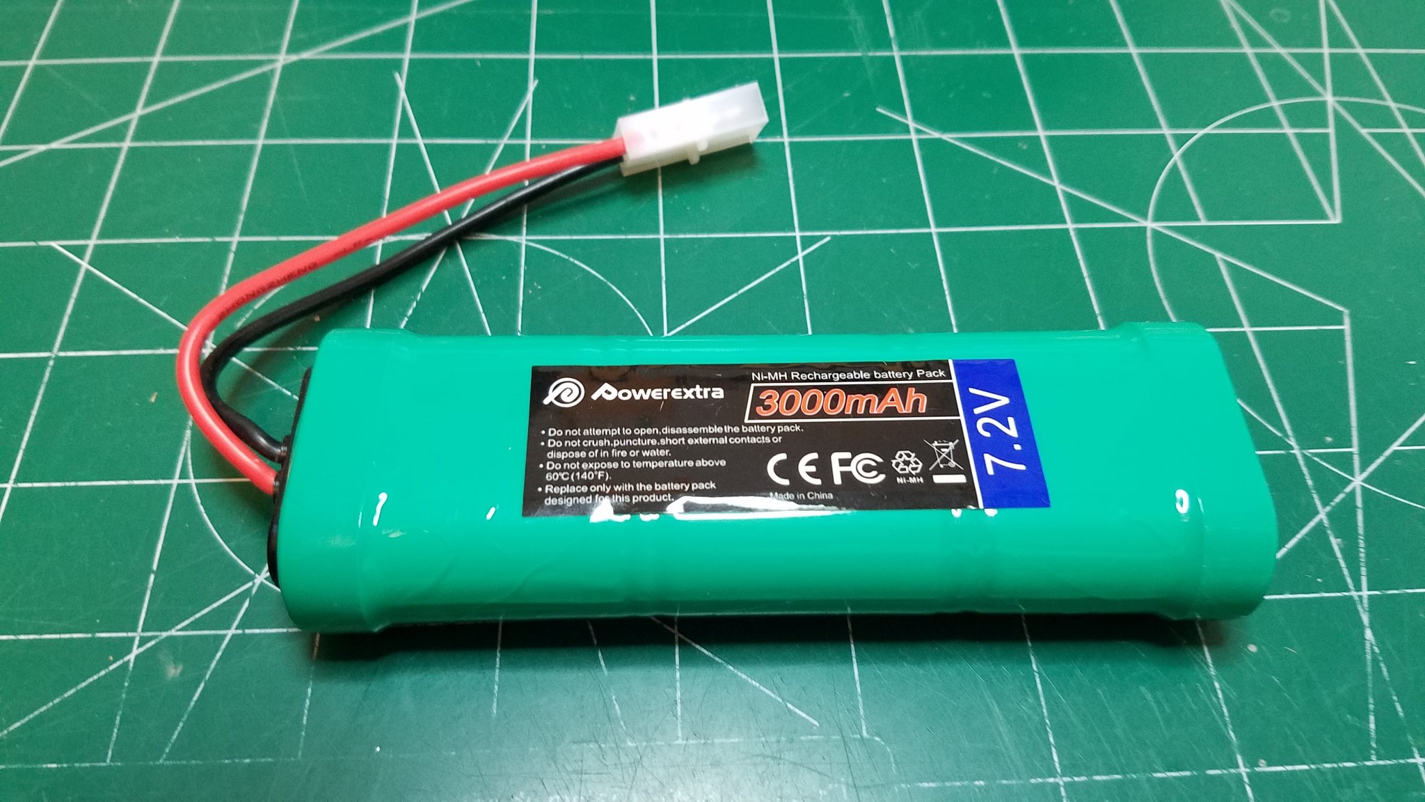
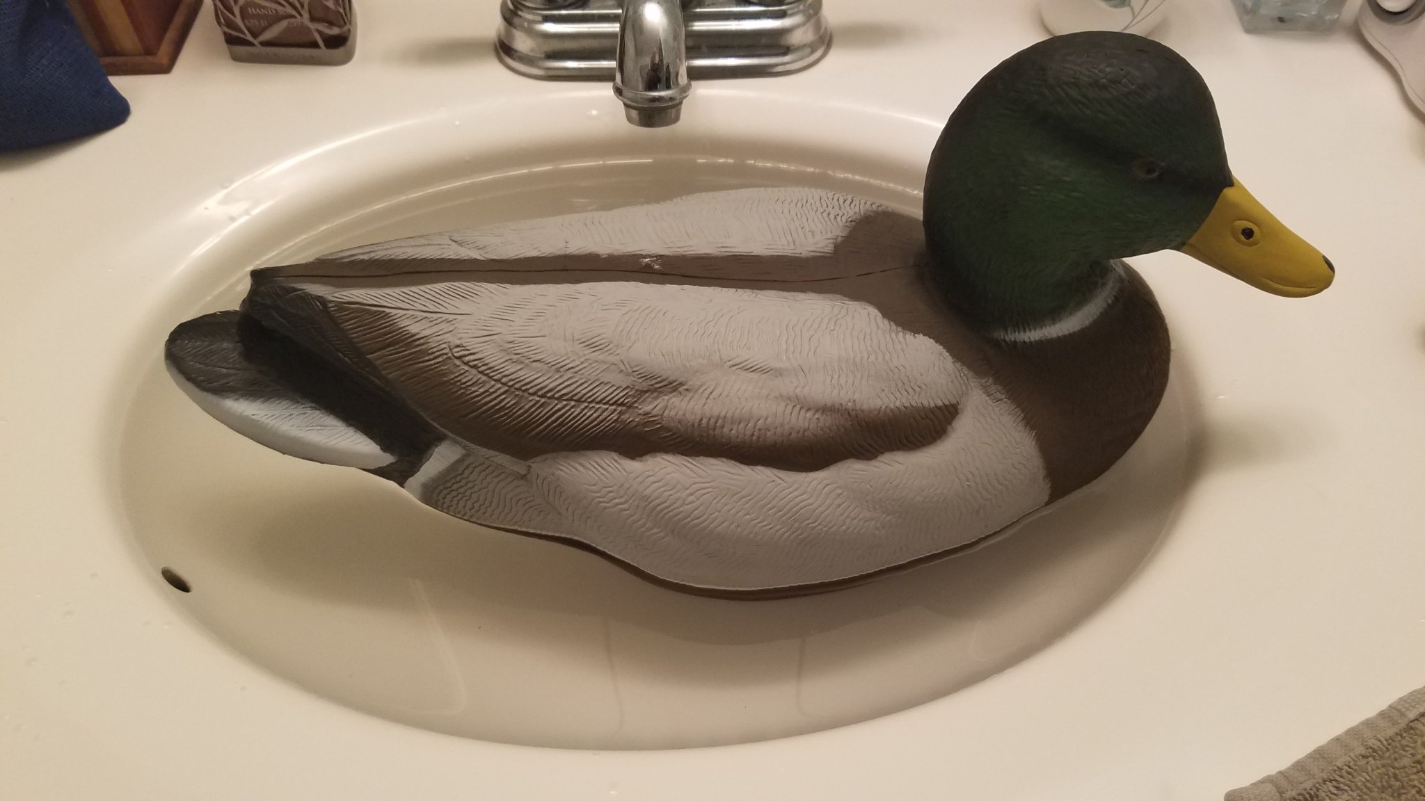
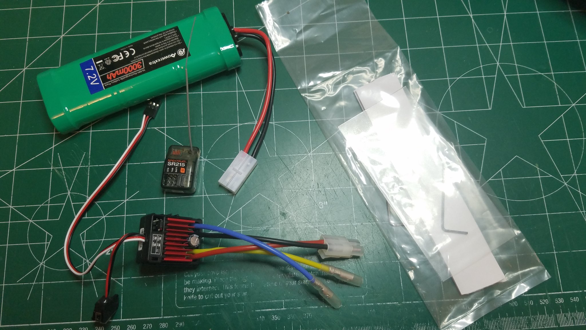
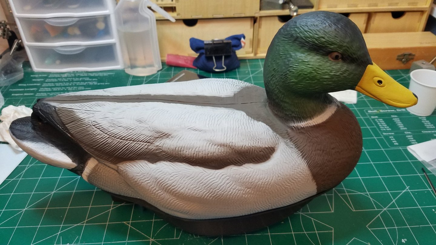
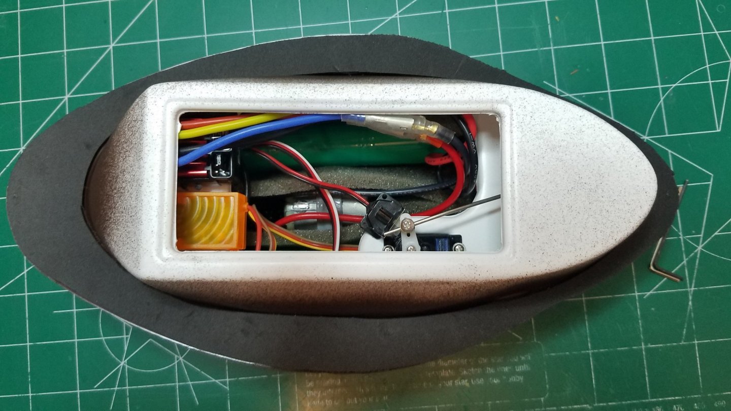
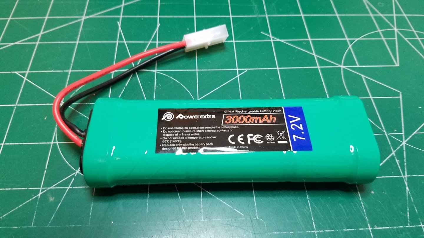
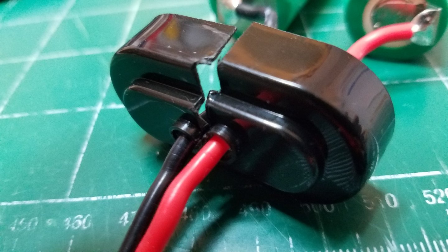
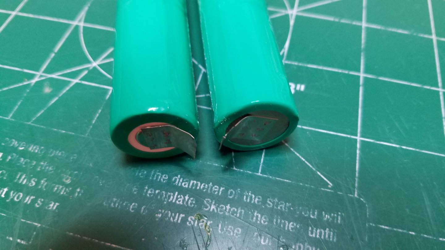
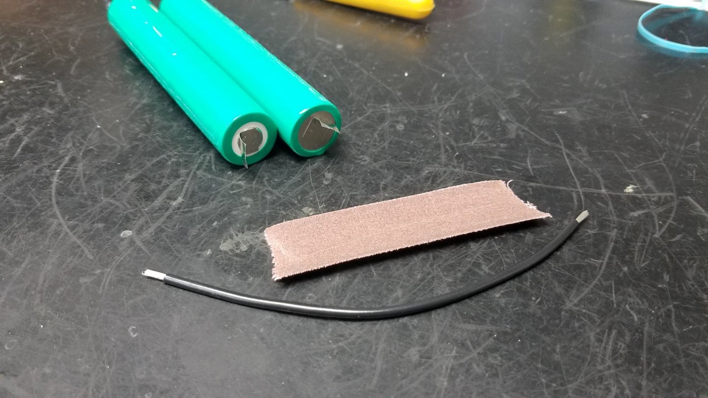
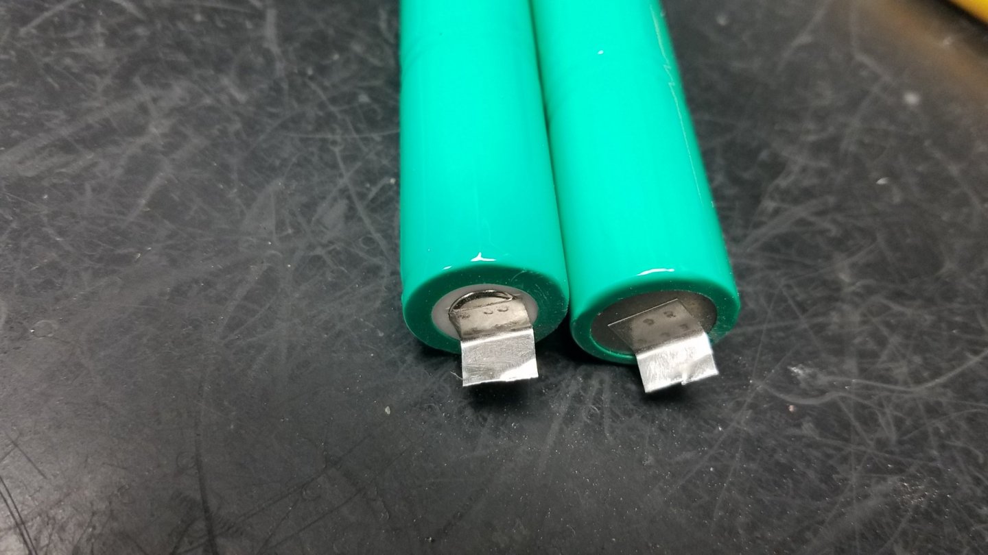
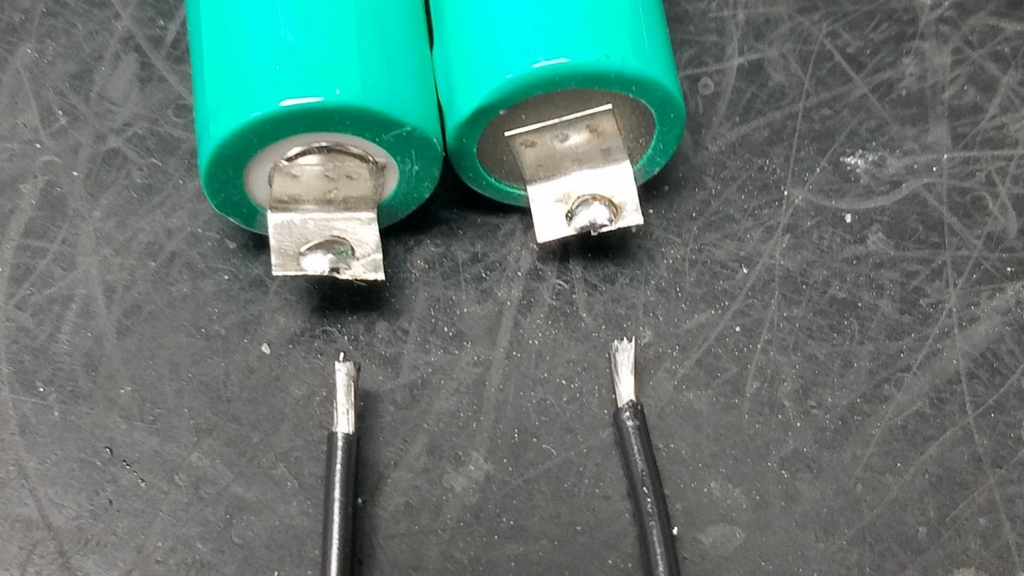
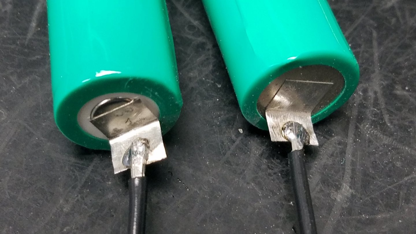
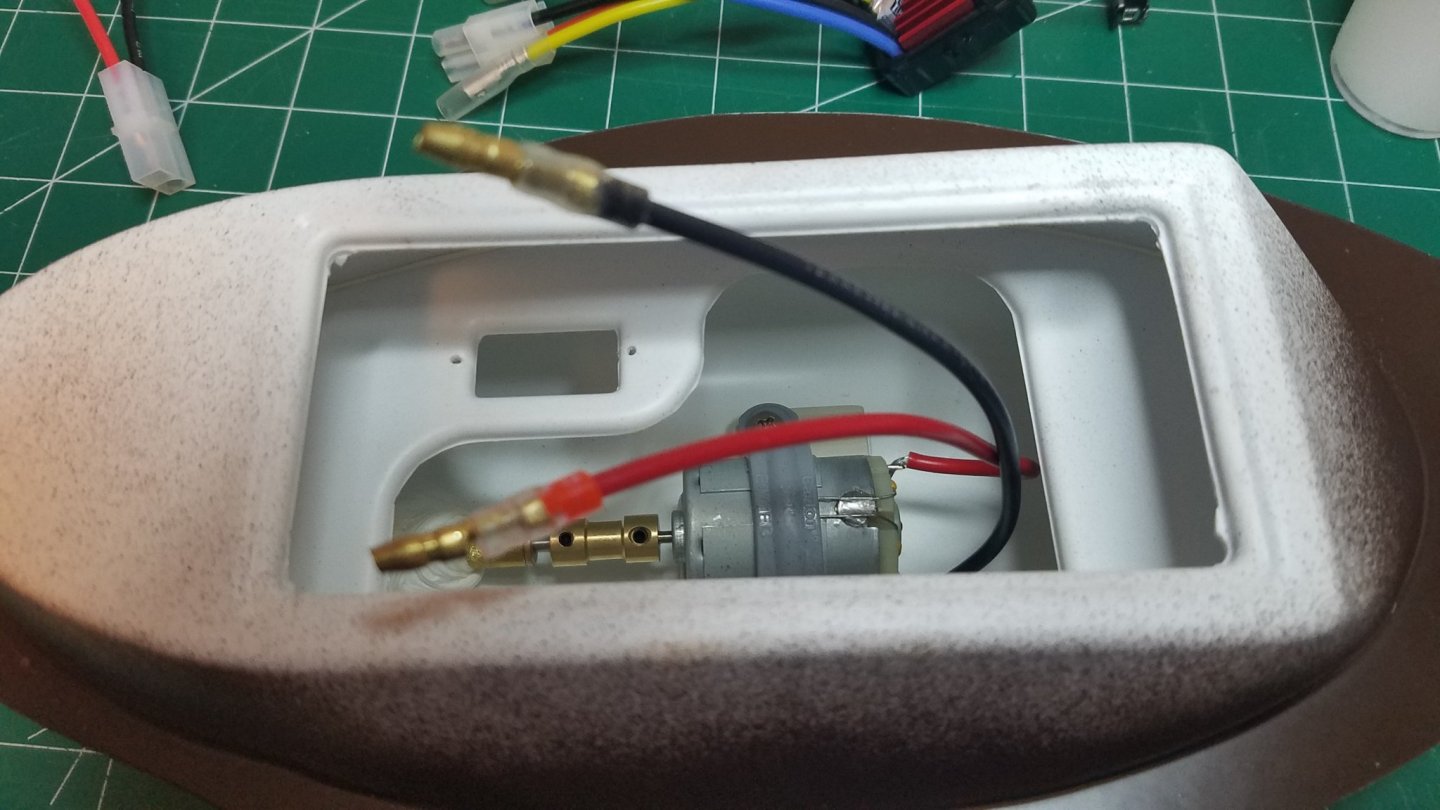
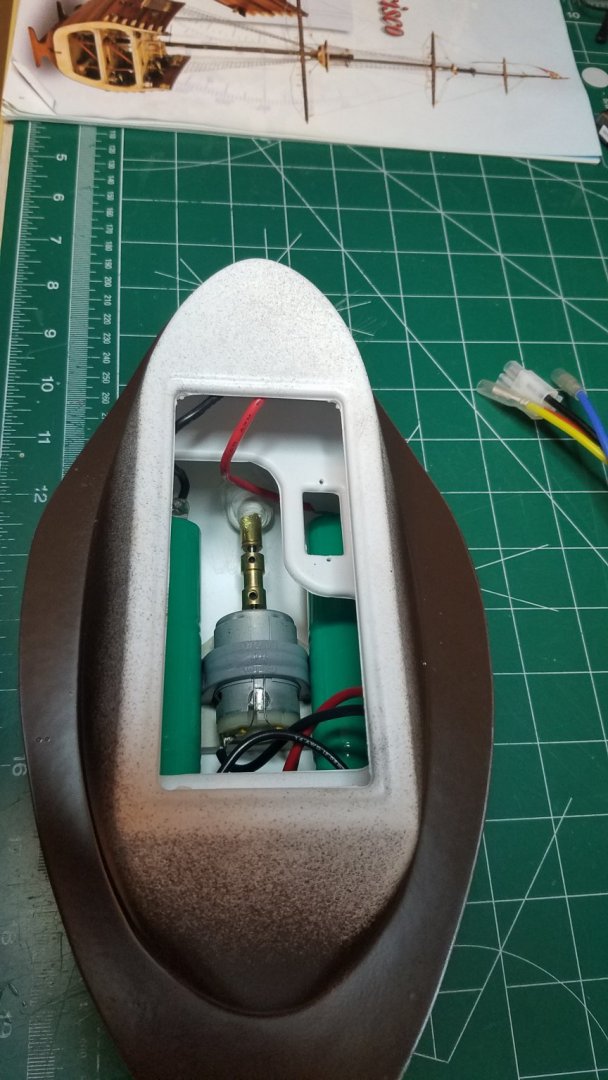
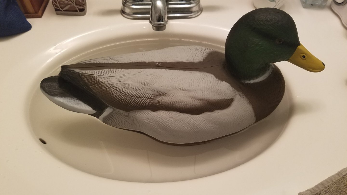
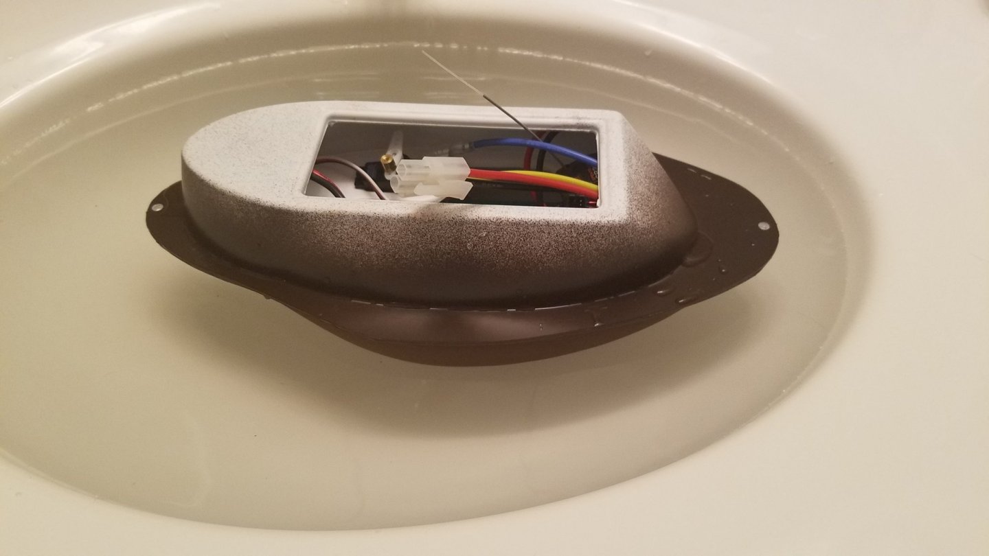
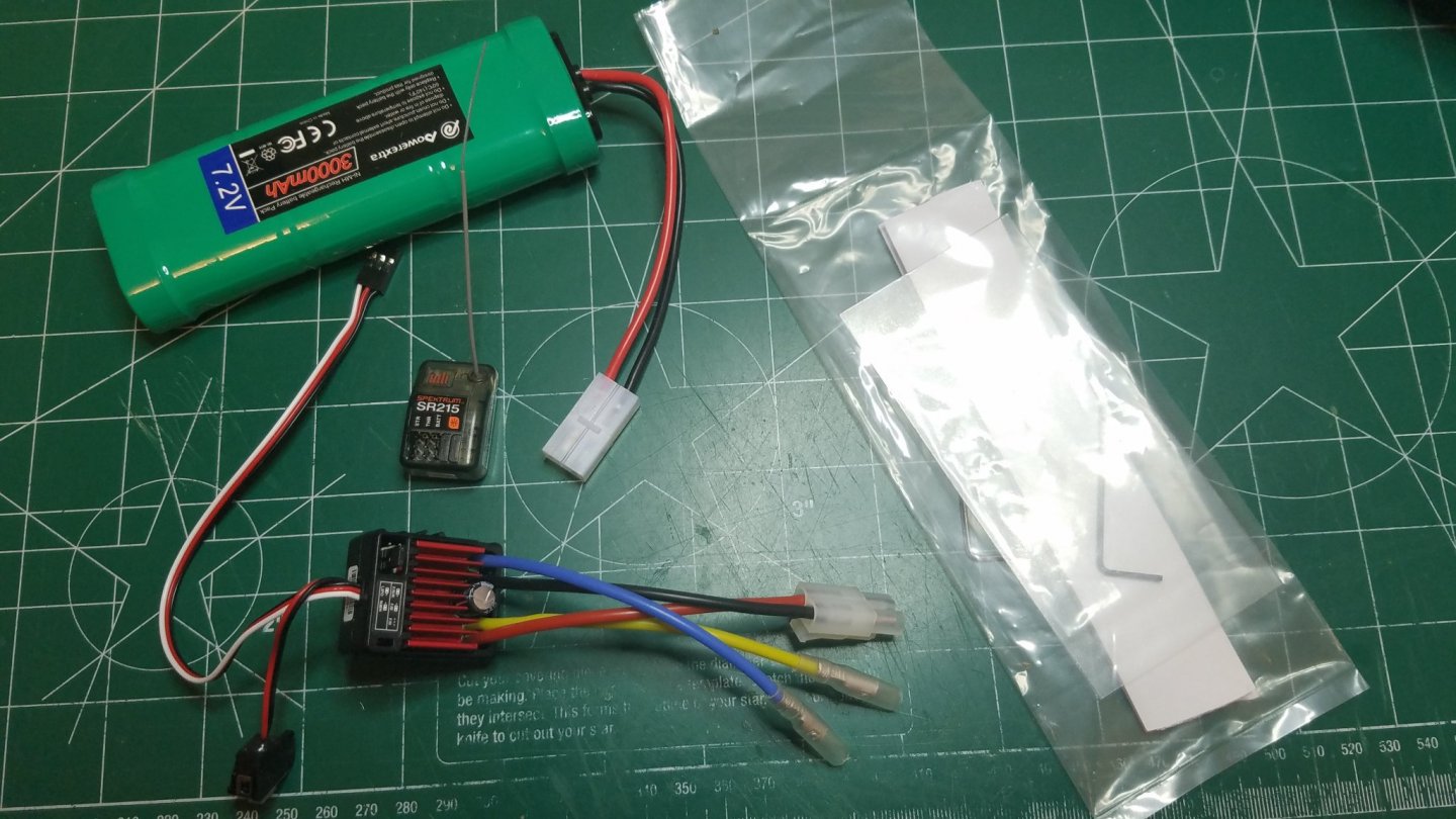
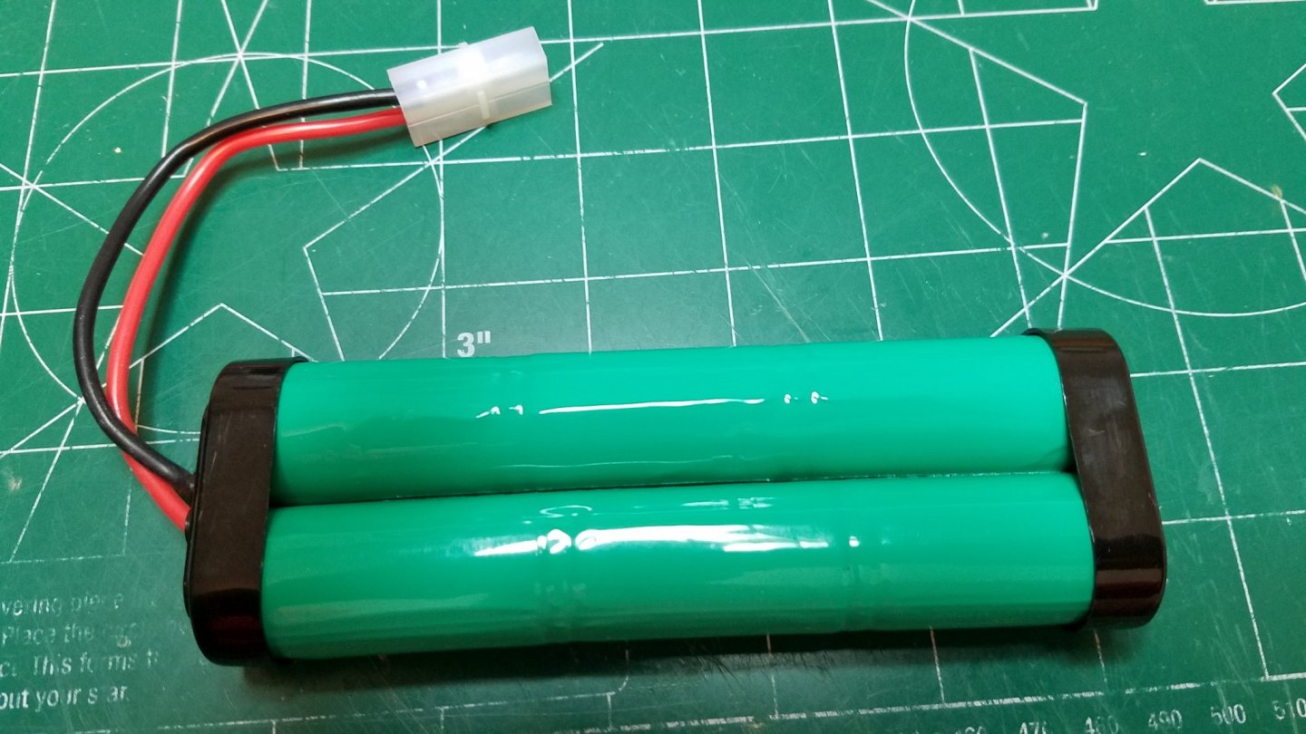
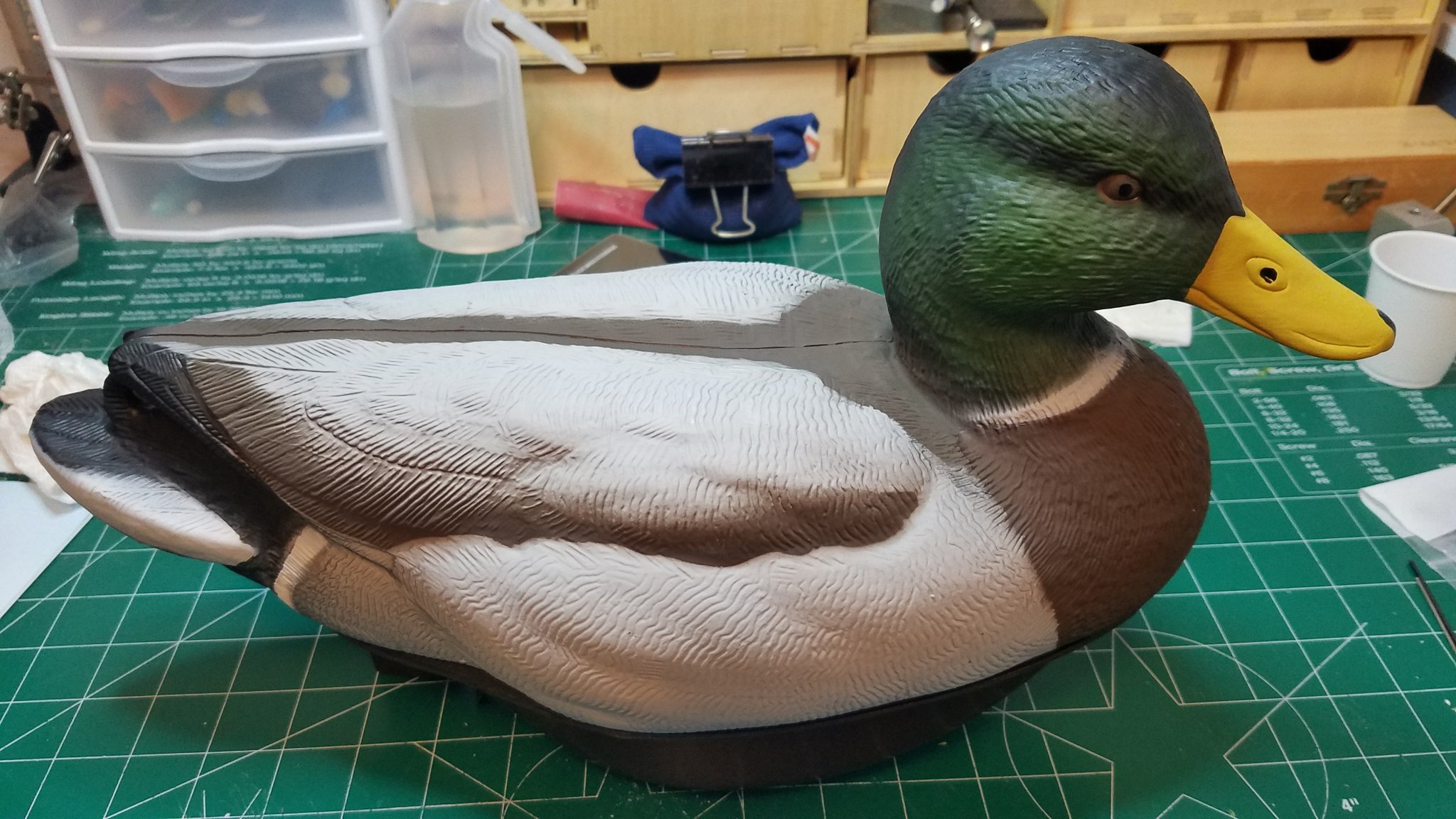
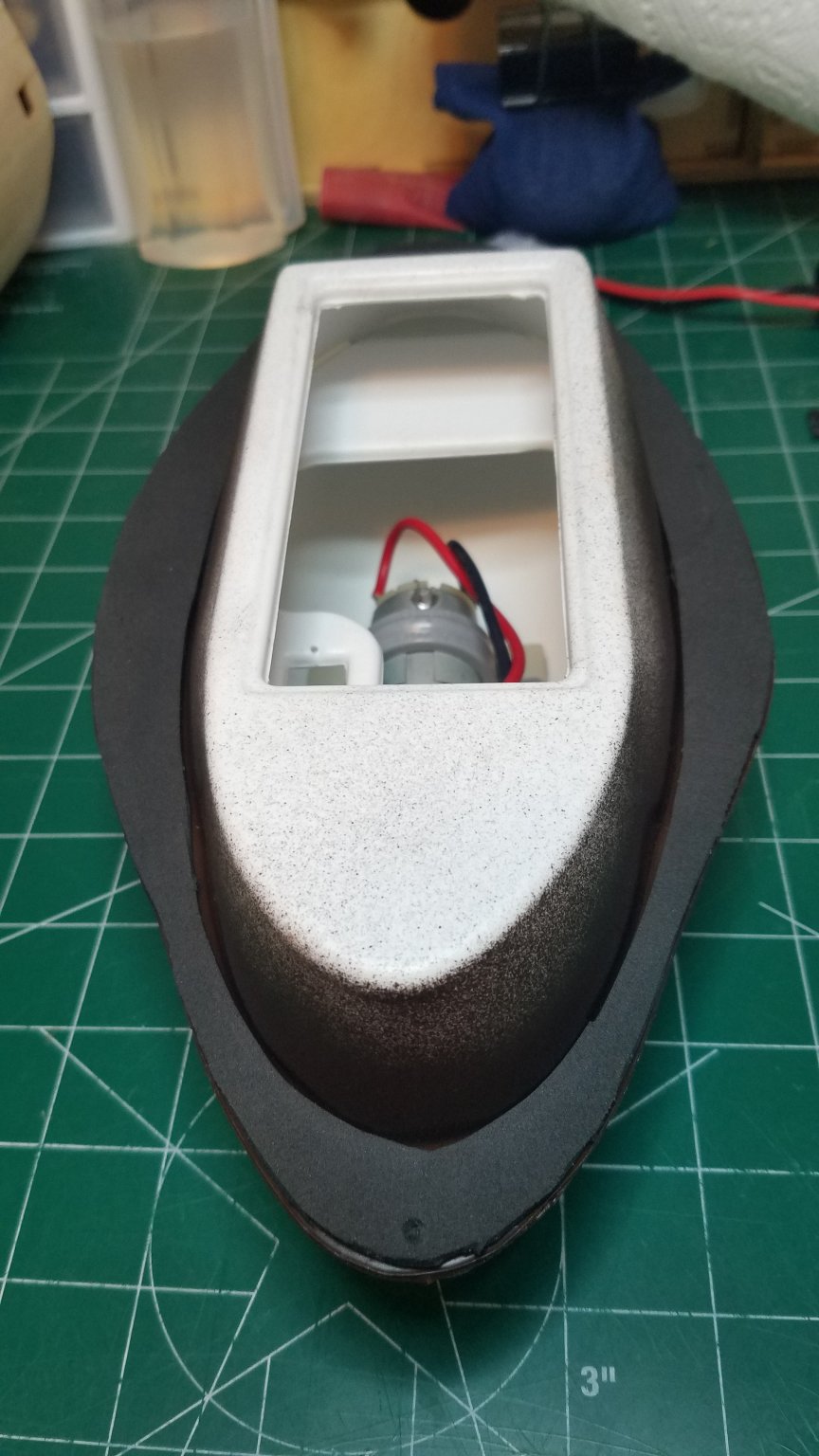
Taking a short break from my San Francisco Cross Section for a little fun and frivolity. I posted this a while back in "What have you received today" and am just getting around to building it. My intention is to gift it to the Admiral and let her chase ducks, coots and geese around our pond while I am sailing my RC yachts. As the title says it is a remote controlled duck from Phil Pace at Vac-u-boat. Besides the nicely painted duck with motor and steering servo the kit includes, a stand some velcro and a couple of allen wrenches. I had to supply the battery, speed controller and receiver. This is the way it comes from the factory, motor and steering servo already installed. A nice little shelf up forward for mounting the electronics but other than that it is pretty tight in there. I decided on a NI-MH battery to cut down on the extra ballast that I already know I will need. Unfortunately I will not fit in the hull without some modification. So first we carefully cut open and remove the outer shrink wrap. Then we snip and remove the plastic end caps. Next we snip the connector strap on the end opposite the wire leads. A piece of #16 AWG wire and some emery cloth and a soldering iron and we are good to go. First we rough up the ends of the connector strap. Then very carefully and very quickly pool some solder on the tabs. Try not to build up too much heat as bad things will happen (Boom). If you don't get it right away let the tabs cool off and try again. Also strip and tin the ends of the wire. Then quickly melt the pool of solder and press the end of the wire into it while it cools. and that is it. In order to get the battery in I had to remove the steering servo. Then lifting the corner of the servo mounting shelf ever so slightly push one side of the battery down alongside the motor. Lay the other half of the battery on the opposite side. They lay in there real nice and very deep in the hull. I will lay some foam padding under them in the final assembly. Once the battery was in I replaced the servo and radio equipment in its approximate locations for a ballast check. Off to the test tank (bathroom sink). As you can see it floats fairly well already. It had a noticeable port list but I swapped the positions of the receiver and ESC and that small change was enough to almost eliminate the list. I added enough lead shot to bring the waterline just above the seam. Not sure if this is good or not but thought it would look more realistic that way. I also plan on putting a foam gasket on the mating surfaces just in case. I did not take a picture of the ballast while it was floating but this is how I did it. As you can see it does not need very much. I was going to mix it with epoxy and spread it in the "bilge" but I think I will divide it up into two small zip-loc bags and lay them in the bilge one fore and one aft of the motor so that it is adjustable. That is it for tonight I will get back to it tomorrow.


- 36 replies
-
- 11
-
-
I am not sure yet. I was going to wait and see how cramped it is in there once I get all the cannon rigging done.
-
Looking good. You should be able to see the light at the end of the tunnel by now.
- 114 replies
-
- 1
-
-
- small
- Peterboro Canoe
- (and 2 more)
-
What method are you using for bending those beautiful ribs?


.jpg.2dc4ce85203d3b3894ca0f453fd36876.jpg)


.jpg.24e6cd979818a85875bfe3d0cb441dd1.jpg)
.jpg.51886e19648760d364fddcbebf87cf28.jpg)