Jeff T
-
Posts
247 -
Joined
-
Last visited
Content Type
Profiles
Forums
Gallery
Events
Everything posted by Jeff T
-
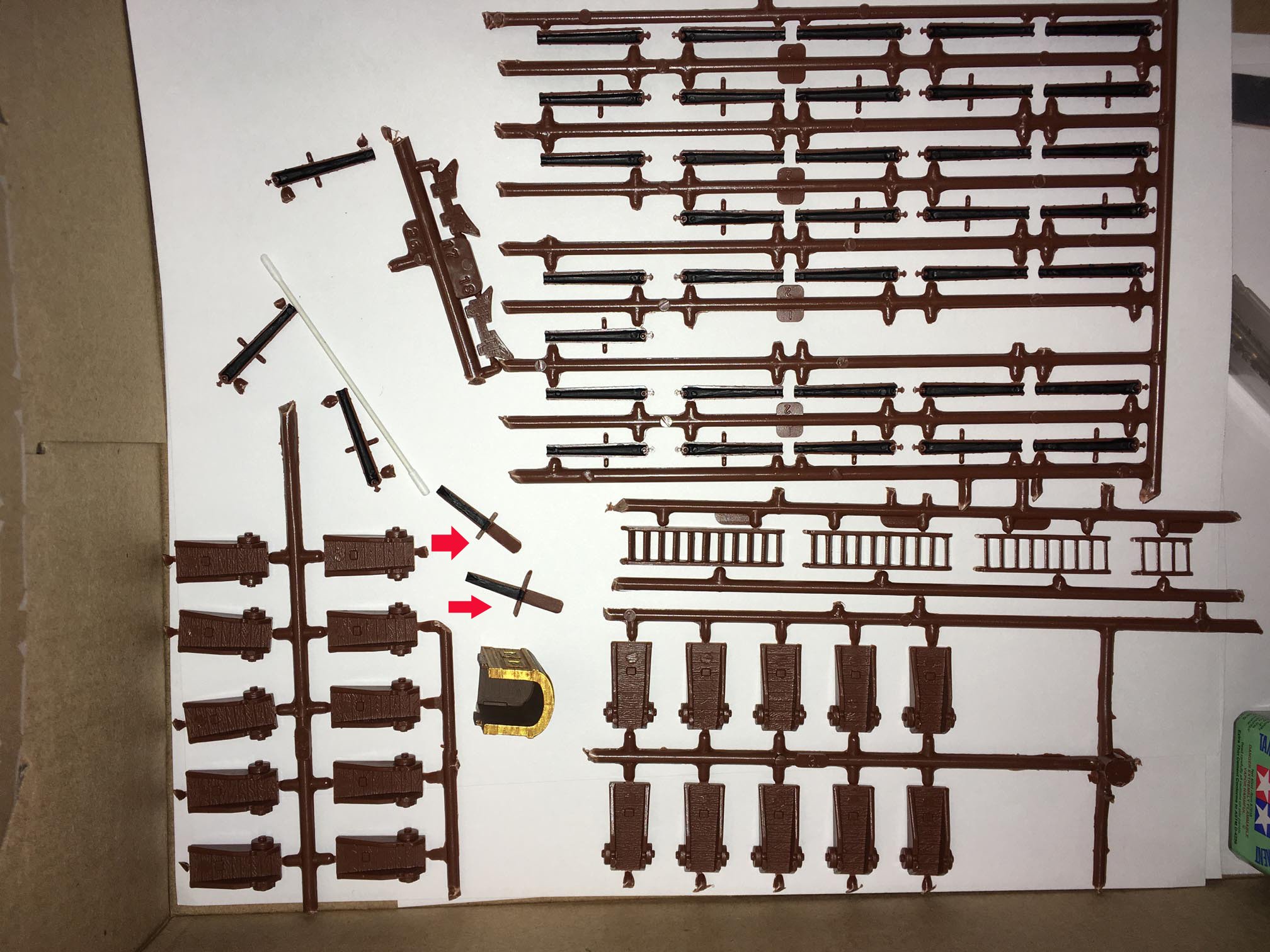
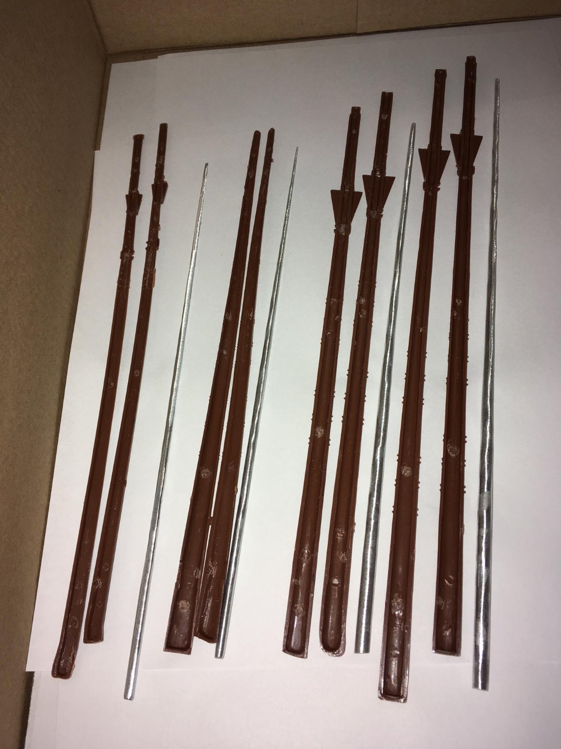
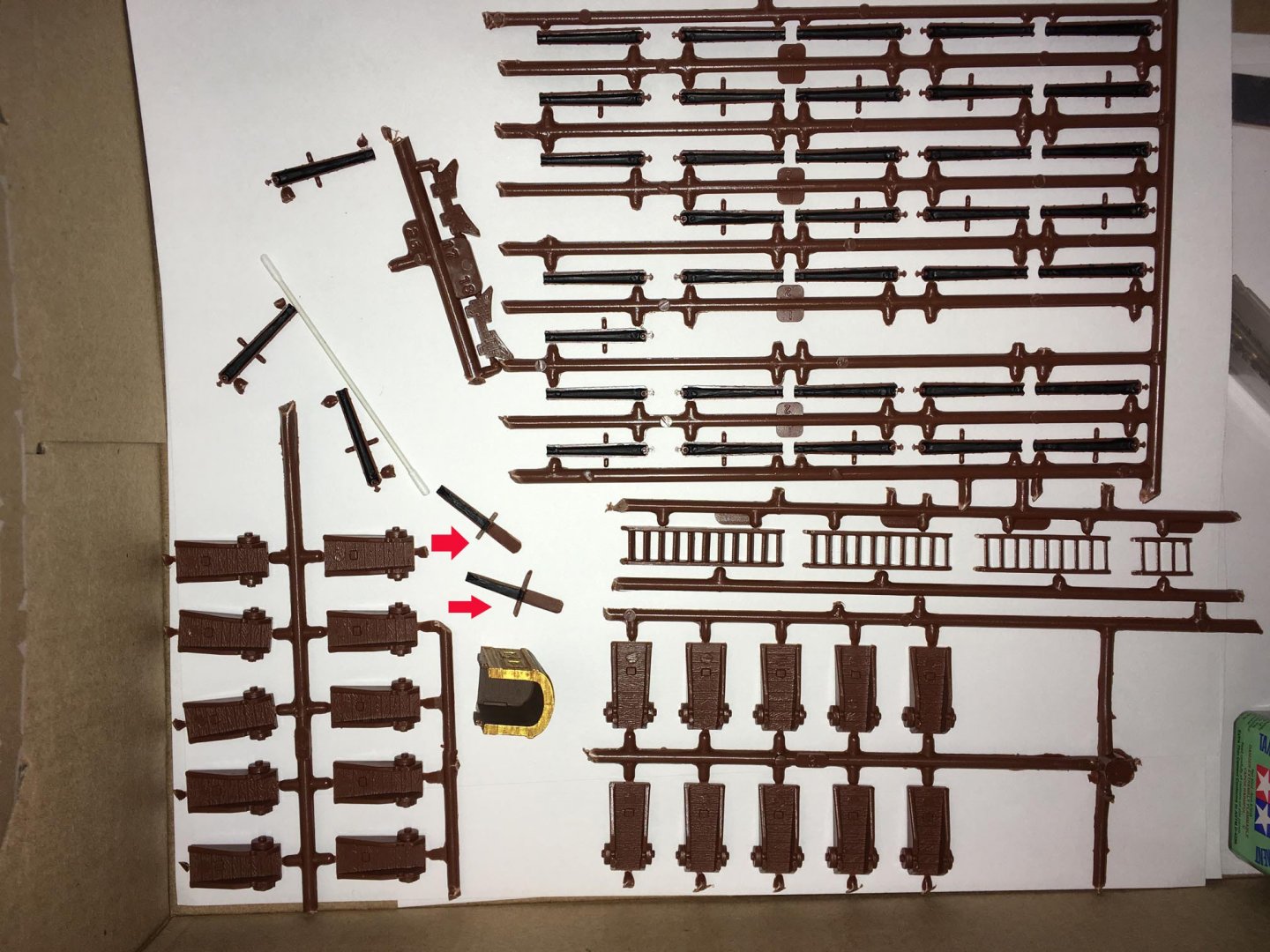
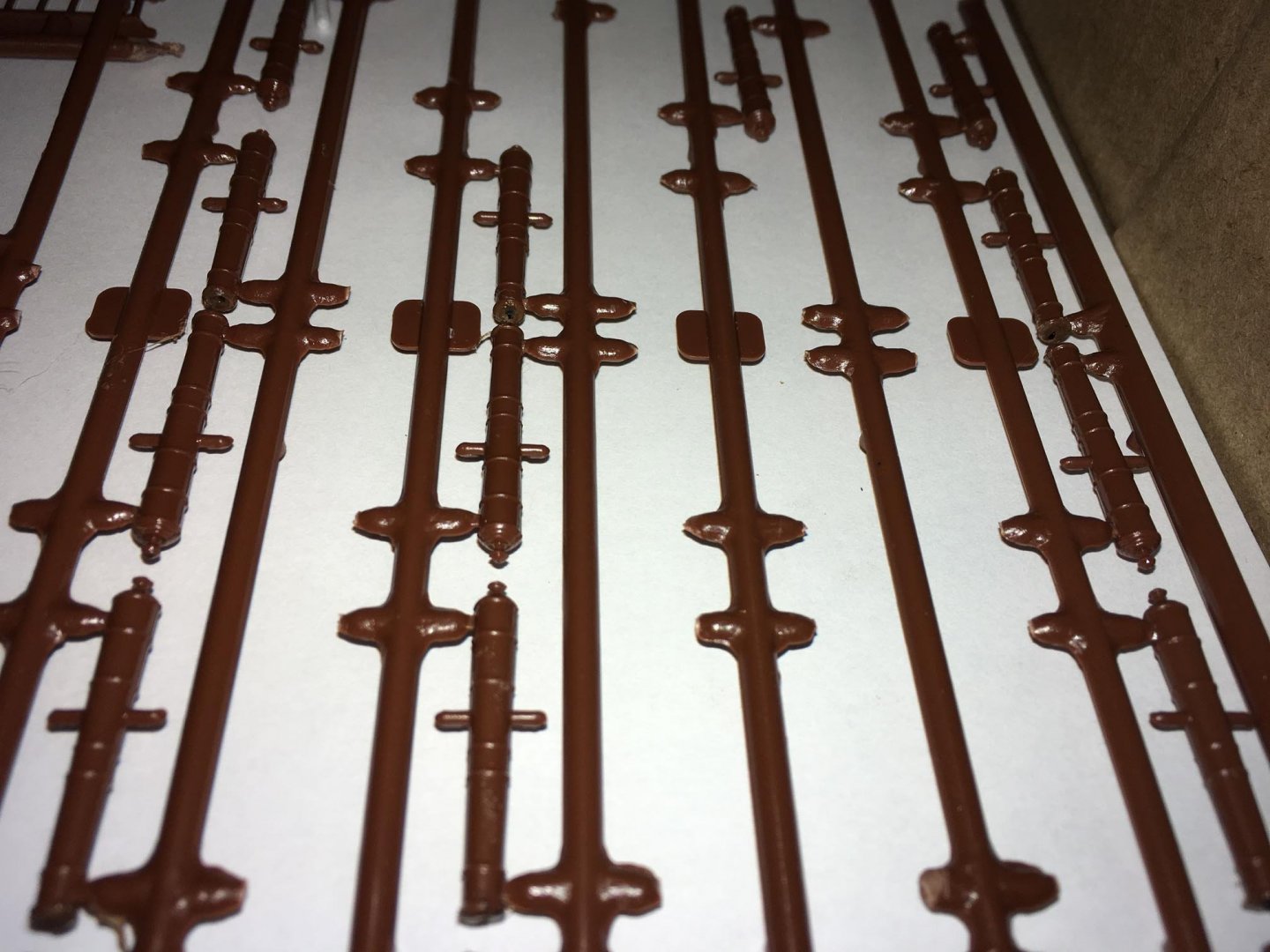
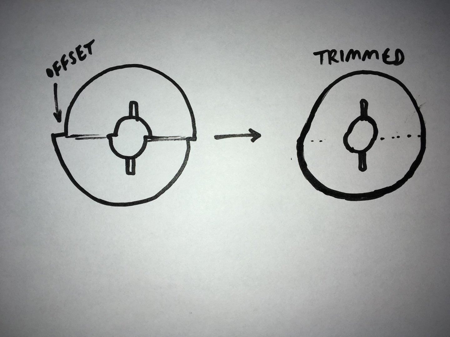
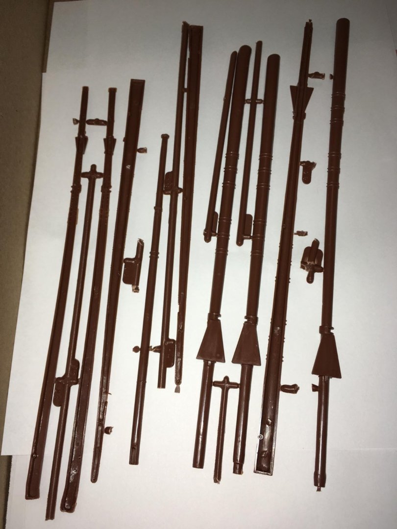
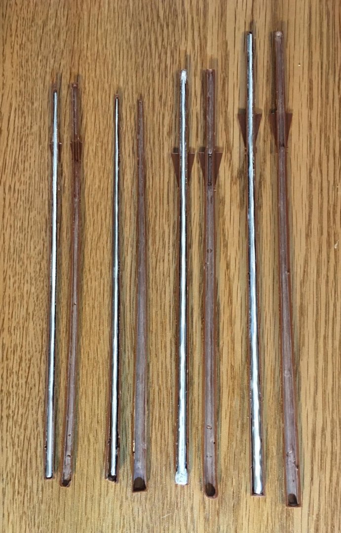
My next project is working on the cannons. It seems like it would be fairly straightforward: the two halves of each cannon are cemented together and then the piece is mounted on the gun carriage. Unfortunately, since the molds for this kit are old (1970s, I think), the pieces sometimes do not fit together very precisely. So a lot of work is required to get rid of the mold lines. In my kit, one of the cannon halves was missing, and I lost another one. Fortunately, I remembered how Backer had used sprue to make cannons for his HMS Bounty, so I tried it out by making a couple of cannon halves. The photo below shows that first, I painted the insides of the cannons black. Red arrows point to the two cannon halves that I made from sprue. Next, I glued the cannon halves together while most of them were still on the sprue. The muzzle openings were rarely perfectly round, and often had a gap between the top half and the bottom half. To try to fix this, I applied some "molten" styrene to the muzzle which, when it is totally dry and hard (need to wait a week or more), I can sand them and bore them out round. I have been working on the carriages, too. The molds were apparently offset by only a fraction of a millimeter in some cases, but when you trim them mold lines down, the wheels are not perfectly round. I will just have to accept that as an artifact of the kit. The drawing below shows what I am describing (I don't yet have a photo): These end up being reasonably round enough so that it hopefully won't be too noticeable in the model when everything is done. I will probably place the more contorted ones in the forecastle or beneath the half deck so that they aren't as visible.
-
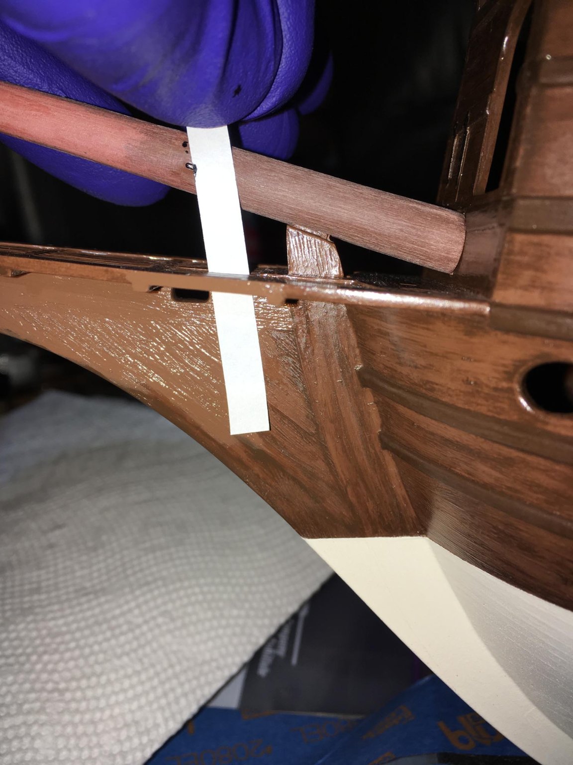
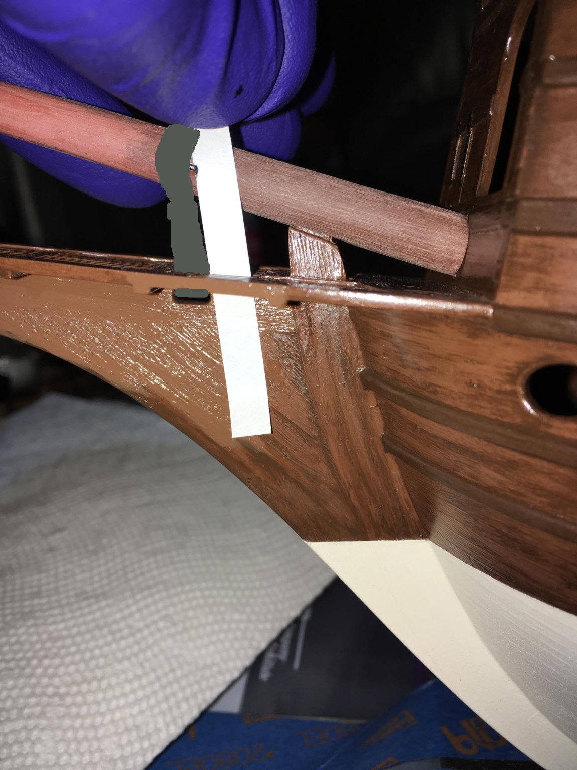
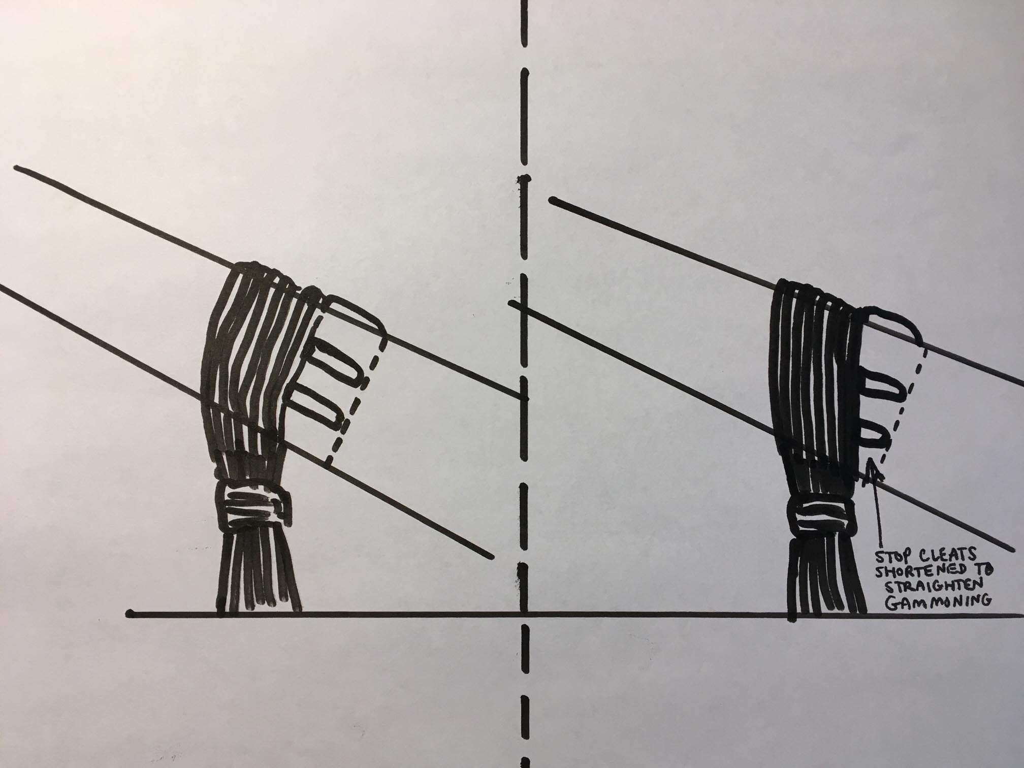
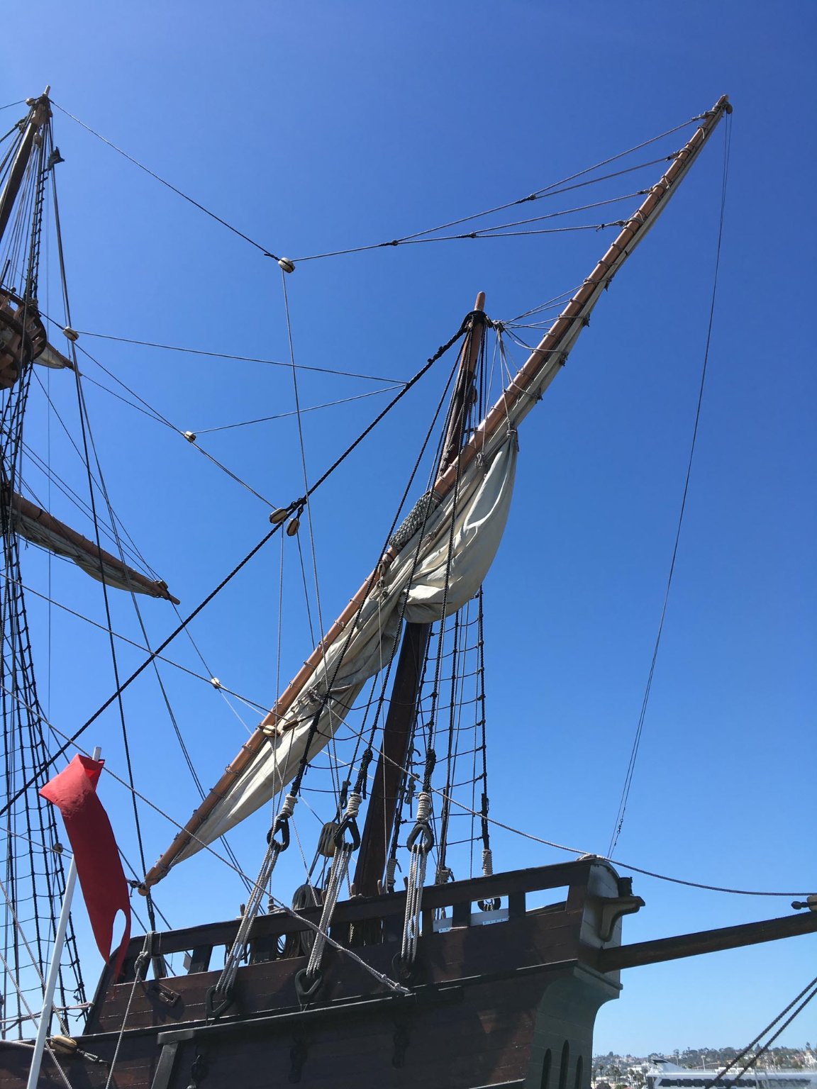
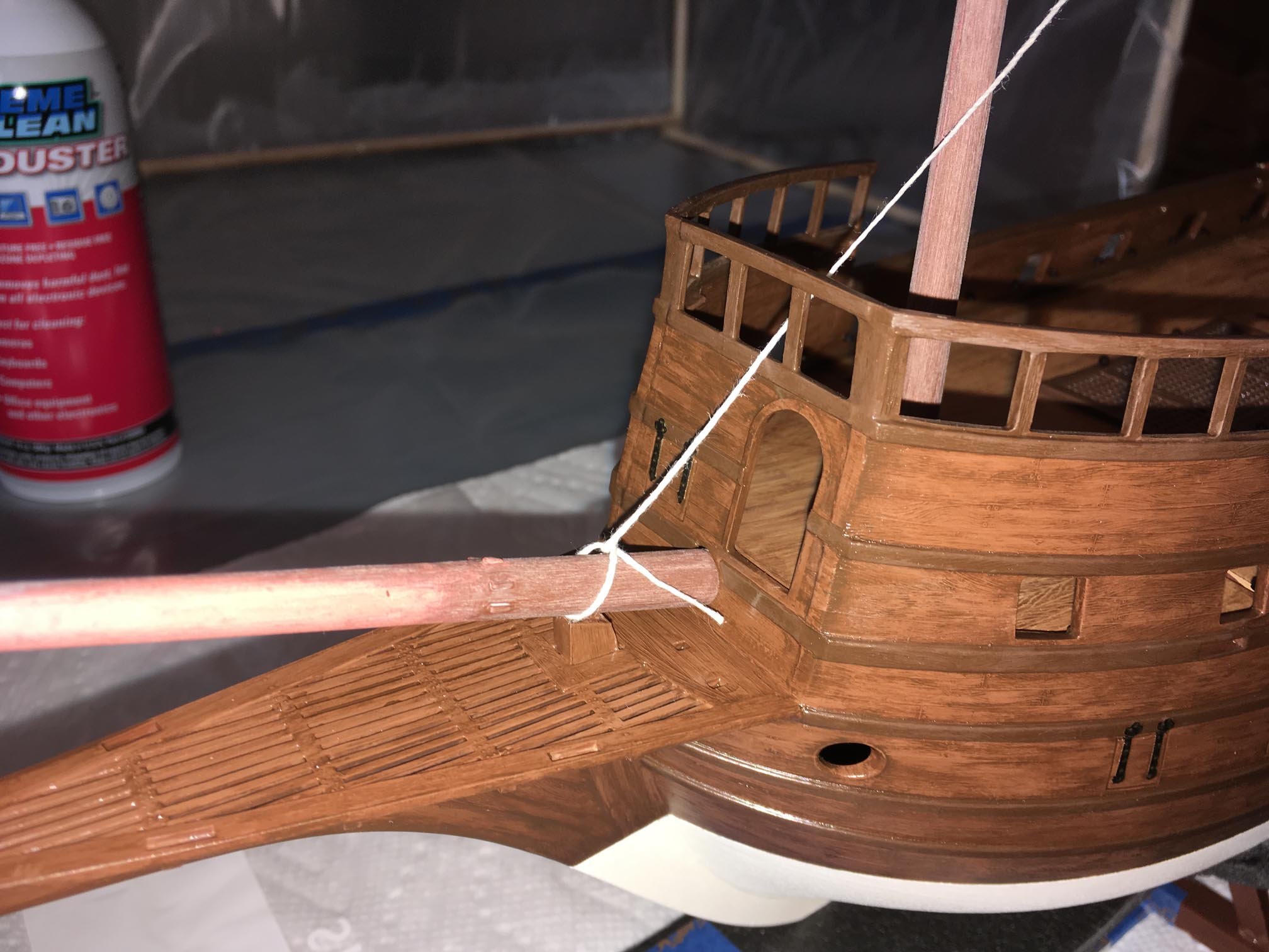
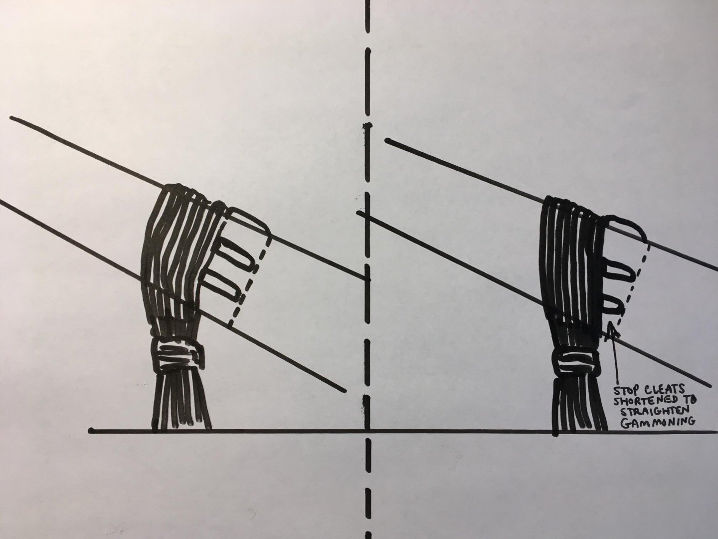
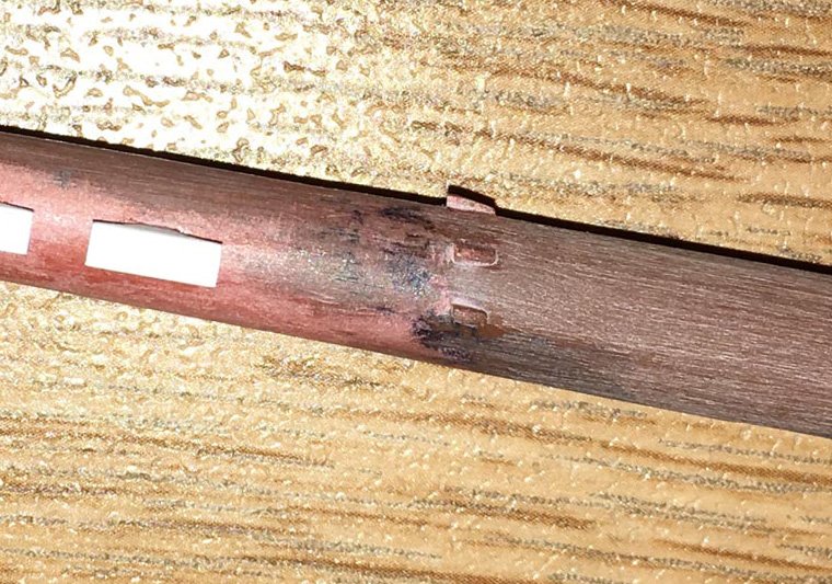
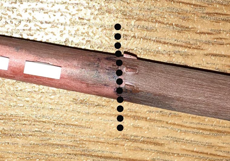
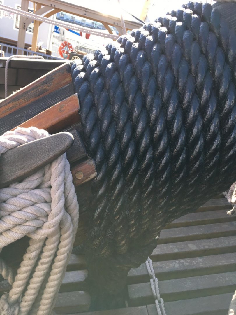
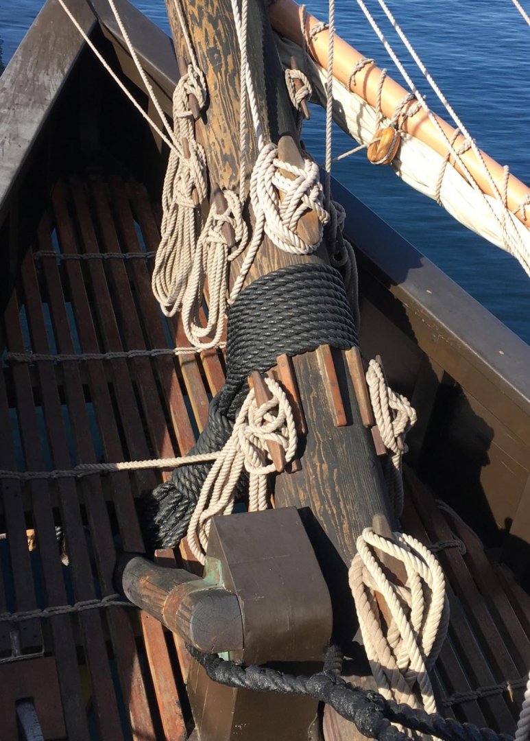
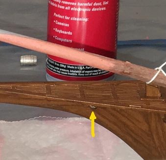
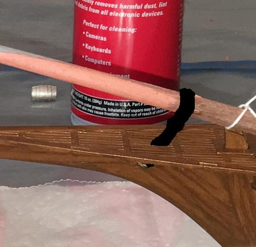
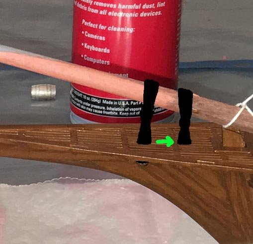
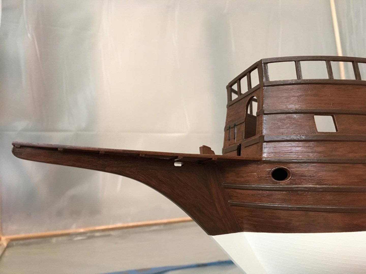
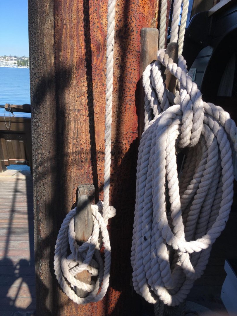
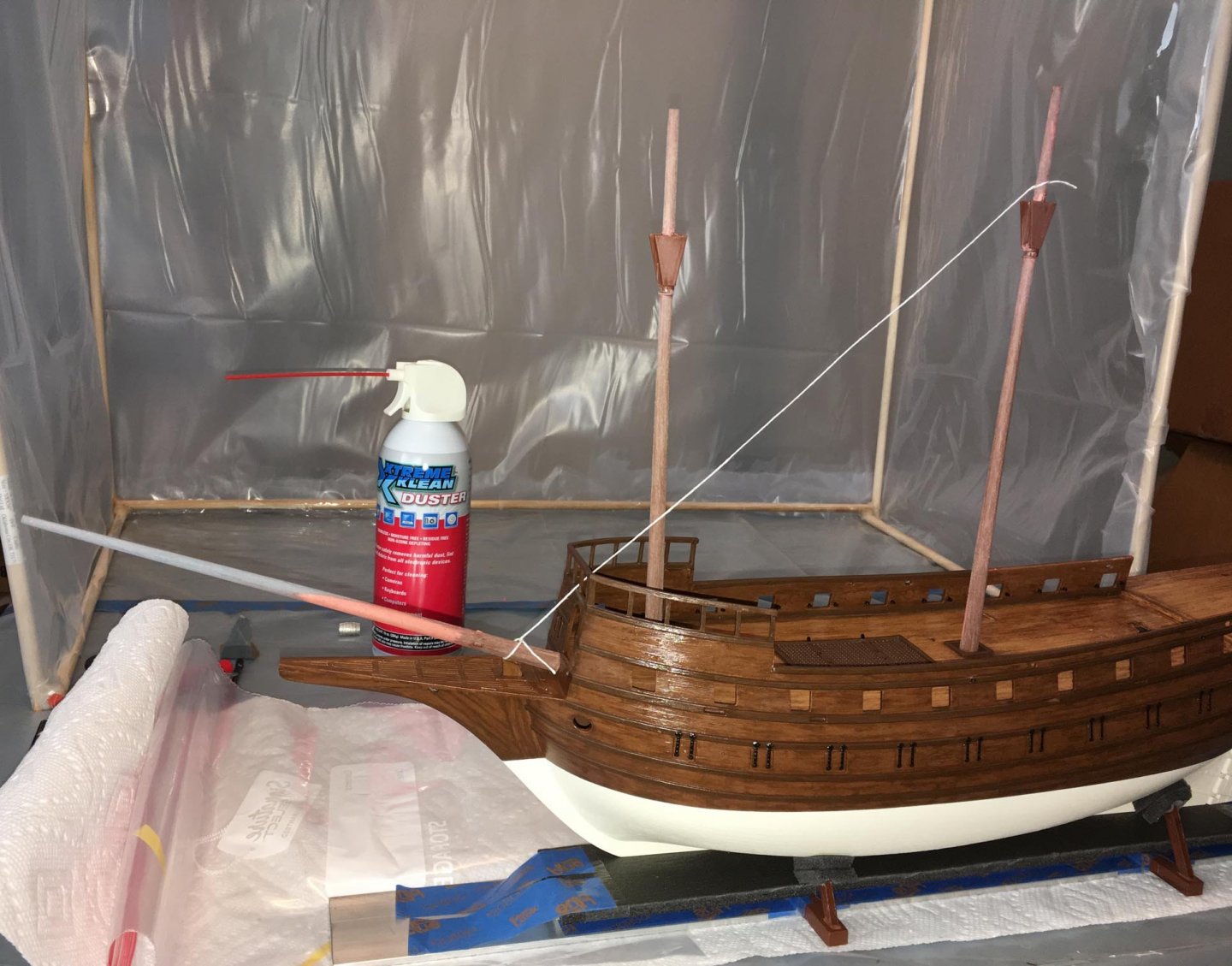
2) I also modified the stop cleats on the bowsprit. The photo below shows me holding a straight piece of white paper inserted through the grating in the beakhead floor, right behind the new gammoning hole (with repainting in progress). It means to demonstrate the trajectory of the gammoning, which will be right in front of where the strip is located. The uncompleted bowsprit is dry-fitted in place. The end of the lower stop cleat on this port side is marked black (follow green arrow): If I were to do the gammoning around the bowsprit against the stop cleats as they are, it would be a little "kinked" rather than "straight up" (see the grey virtual gammoning): So to avoid the "kinking", which seems to me might add additional strain on the lower cleats, I decided to trim the cleats back at an angle as they go from top to bottom (see the drawing below): Here is how they look now (the bowsprit is angled in the photo as if it would be angled above the beakhead): I drew a dotted line to show that the gammoning can be put straight against them: On the galleon replica in San Diego, the gammoning is also mostly straight, with the forward ends of the stop cleats angling a little backward with respect to the axis of the bowsprit as they go from top to bottom: (


-
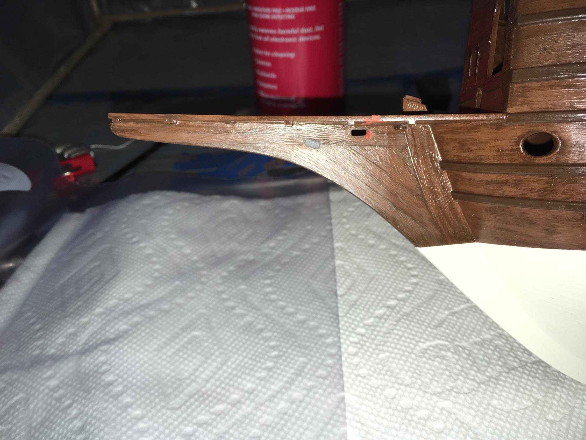
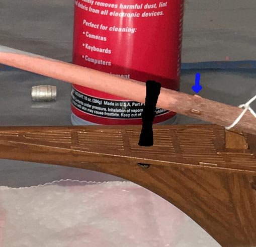
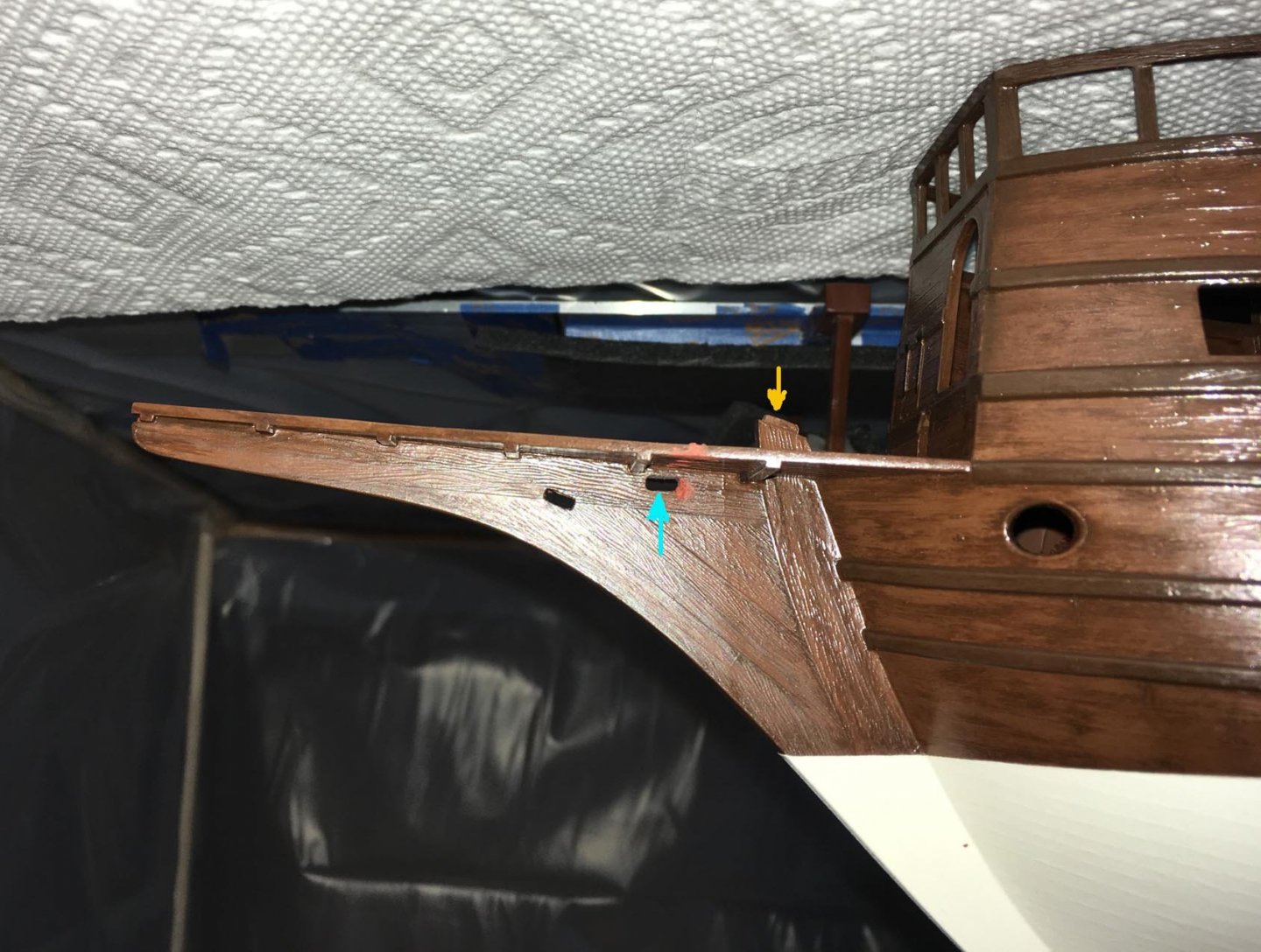
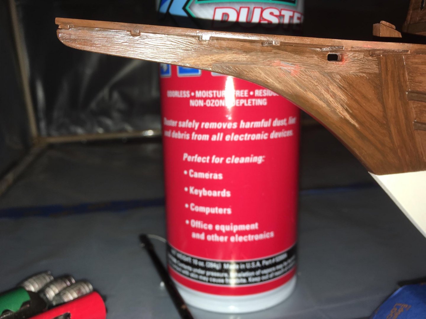
I made a couple more modifications: 1) On the kit's bowsprit, there are small stop cleats molded in place: Ideally, I would want the gammoning to abut the stop cleats, like this: However, as you can see with the (work in progress) bowsprit dry-fitted in place, the gammoning hole (goldenrod arrow) is a bit far forward in the knee of the head: So, if I did the gammoning through that hole, bringing it vertically upward, it would look something like this: The stop cleats are by themselves and further aft (blue arrow above). I could push the gammoning back so that it abuts the stop cleats, but that looks awkward: Or, I could move the whole gammoning aft (follow the green arrow below, and note that the aft gammoning would replace the forward gammoning in the picture): I decided to move the whole gammoning, and to do this required that I move the gammoning hole further aft in the knee of the head. The photo below shows the location of the new gammoning hole (indicated by the aquamarine arrow), which is closer to the stempost (goldenrod arrow): Also note that the new gammoning hole is further up, closer to the floor of the beakhead, such as one may see in a model of the 16th century HMS Revenge. I had to put the new gammoning hole right behind one of the transverse beams below the floor of the beakhead so that the gammoning could still go up through the grating of the floor. Repairing (filling in) the old gammoning hole, and "scribing" wood grain: Here it is after some repainting: Here is a picture with the camera flash: Basically, it will be ready to go when I get to the rigging stage. (The gloss of the paint will also be eliminated by that time with clear matt varnish.)


-
Very nice with the figures, Bill! Enjoyment not only for the grandkids, but also for people of all ages — it adds life and a “story” to the ship.
-
Great Job, Bill! Congratulations!
-
Very nice, Bill! 👍🏻
-
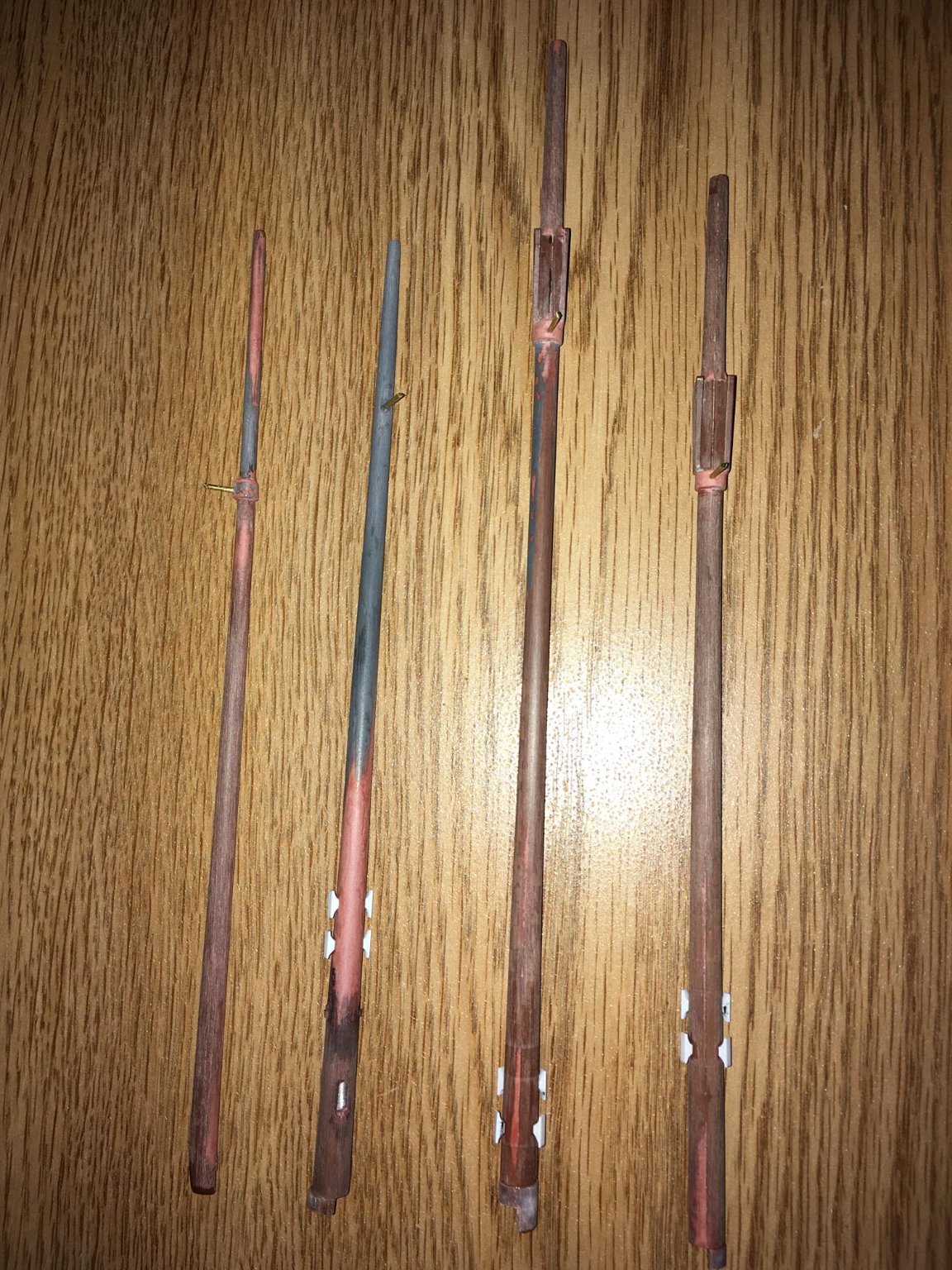
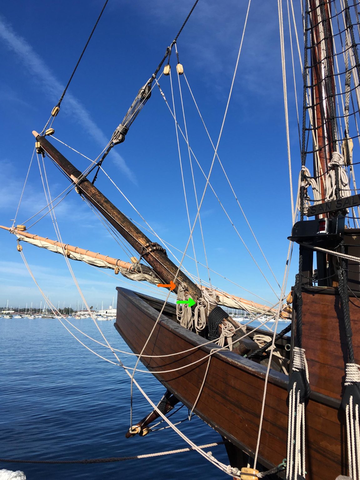
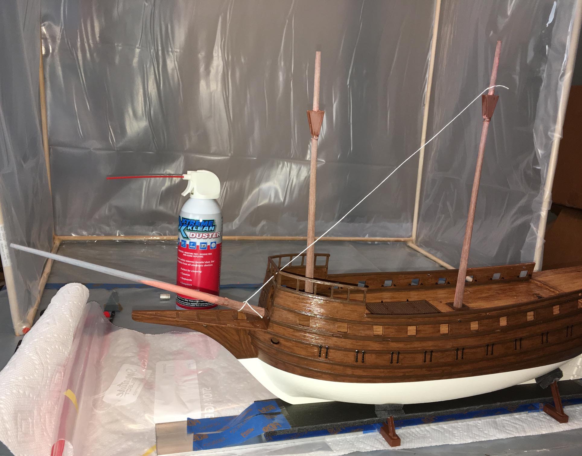
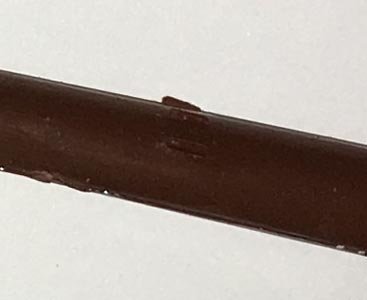
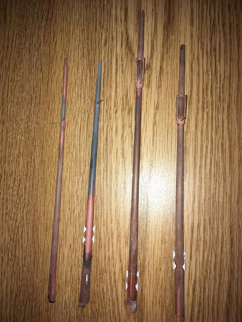
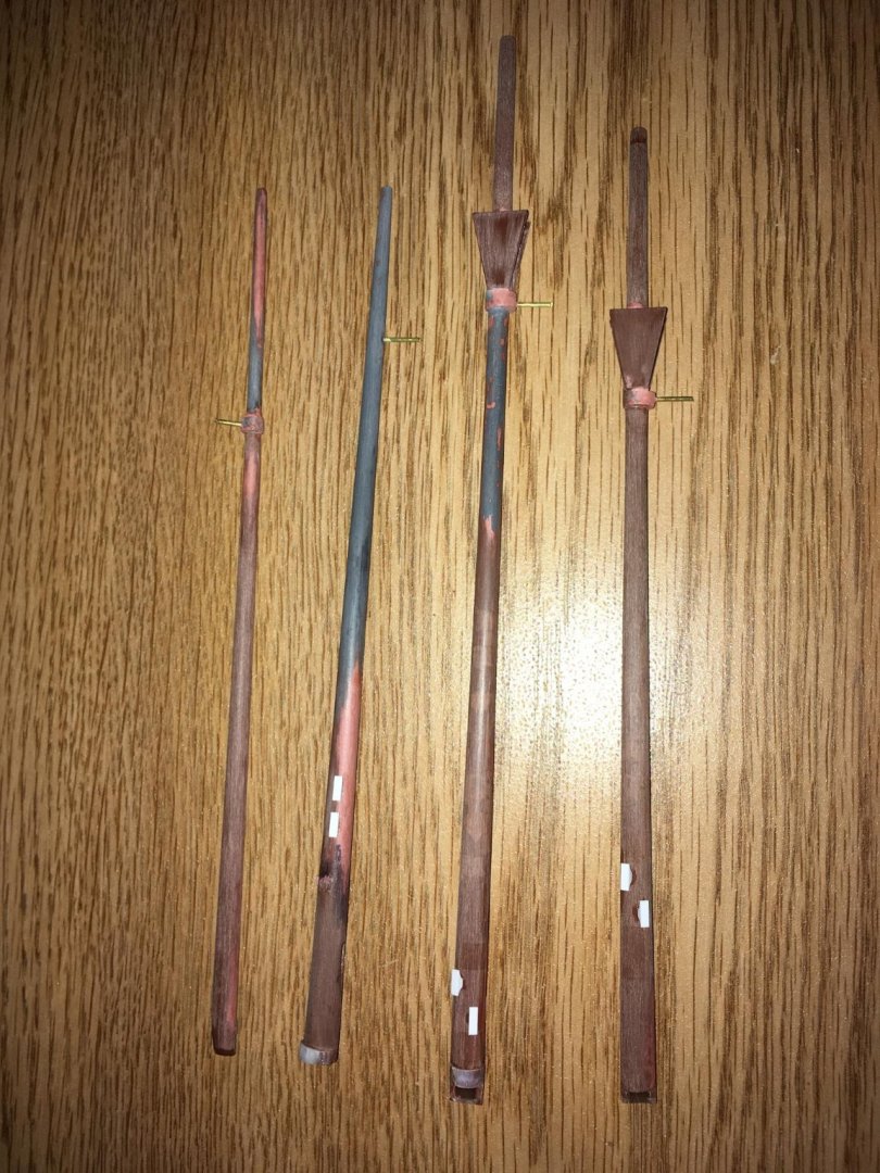
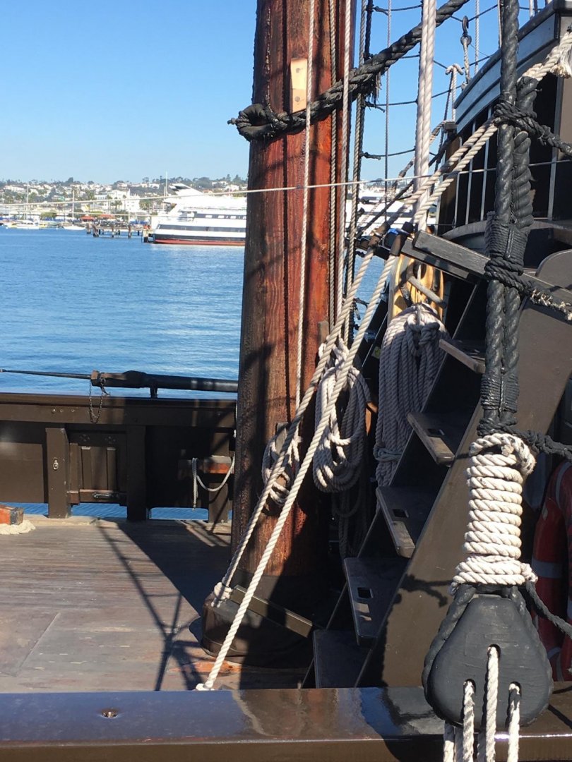
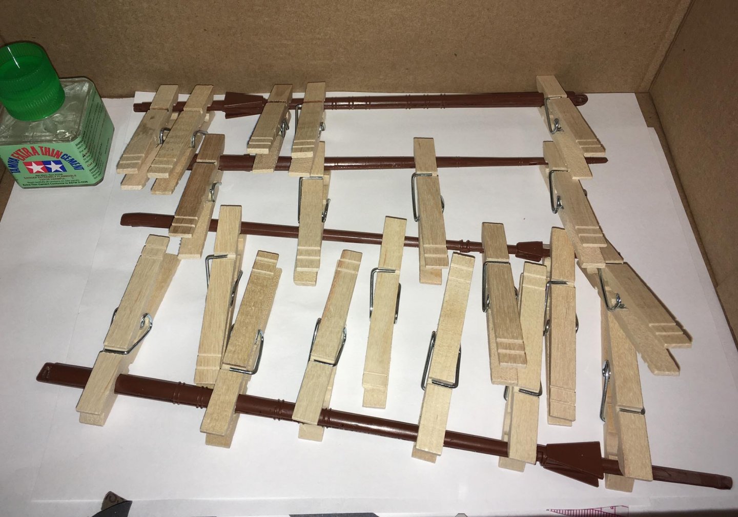
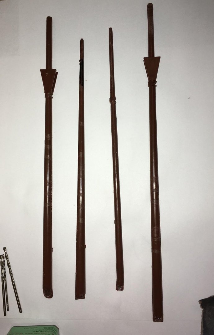
Here is how the bowsprit and masts look with the cleats attached (from left to right: mizzenmast, bowsprit, mainmast, foremast): The square areas of exposed plastic within the reddish putty on the bowsprit in the photograph in my second post from November 14th were made to allow the solvent cement to make strong bonds with the polystyrene cleats. Eventually, after the topmasts are made and attached and after the spars are made, I will spray them all brown and then "weather" them. For rigging, my plan will be to belay the spritsail lifts (port and starboard) to the fore cleats on the bowsprit, and the spritsail braces will be belayed to the aft cleats, like this: (On the port side, the orange arrow points to the fore cleat, which would correspond to my model's fore cleat and you can see that the spritsail lift is belayed there. The green arrow points to the aft cleat, to which the spritsail brace is belayed. There are other cleats on the bowsprit of this replica galleon in the above photograph, but I will not place them on my model -- the rigging may differ a little, and I may instead use the pinrails in the beakhead.) On the same replica galleon, the cleats on the mainmast appear in the photographs below (port view): On my model's masts (mainmast and foremast), I have placed corresponding cleats port and starboard, and these will be used to belay buntlines, which is described in Peter Kirsch's book The Galleon: The Great Ships of the Armada Era (Naval Institute Press, Annapolis, Maryland, 1990), p. 151. (Starboard view, left to right: mainmast, foremast. Cleats are higher up on the foremast because of the forecastle will be right below them, and the mast will go down through the forecastle to the main deck.)

-
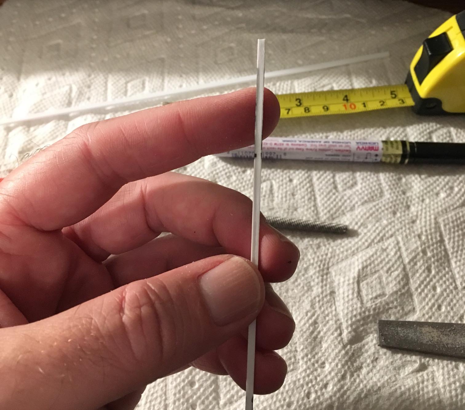
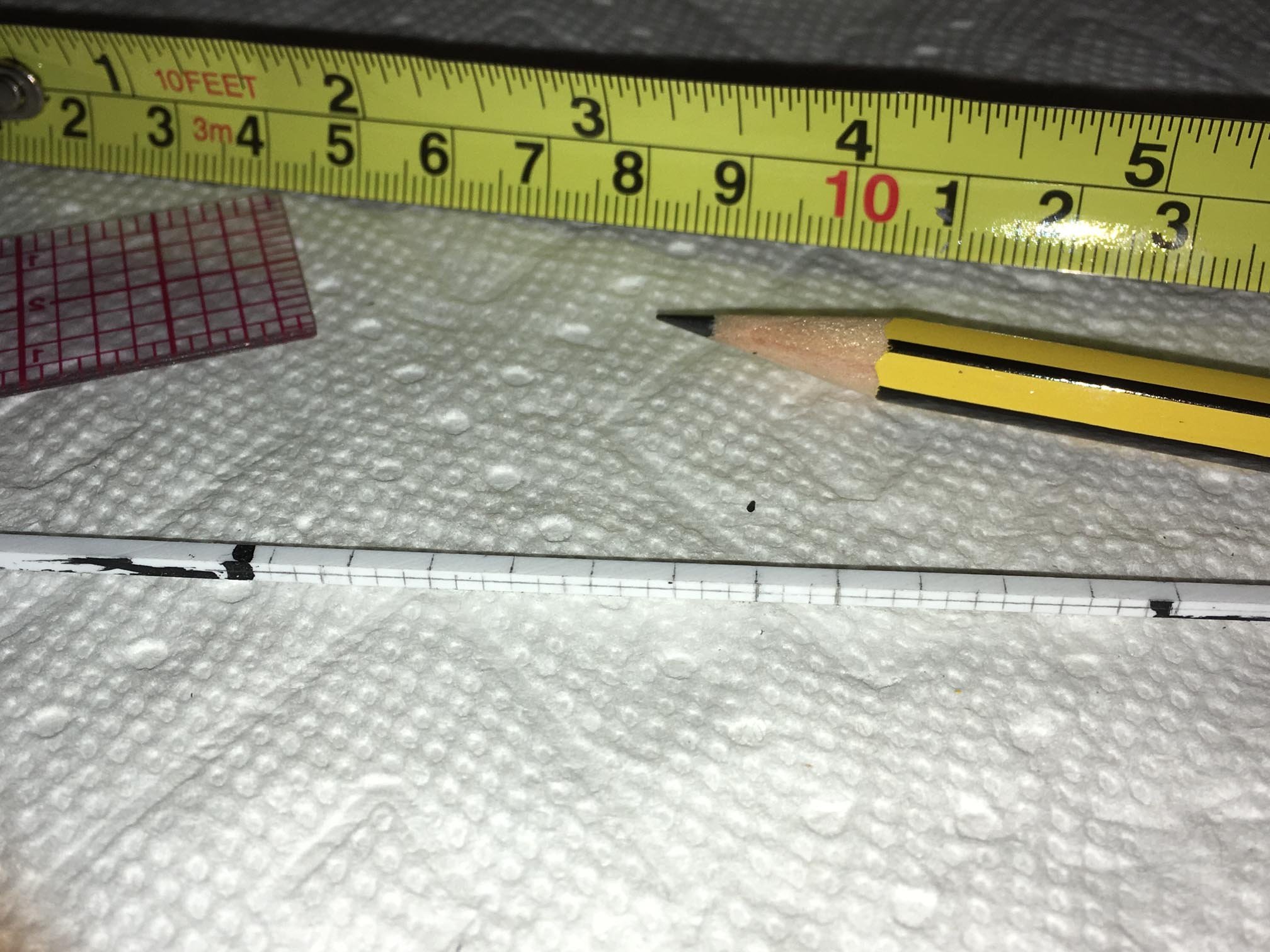
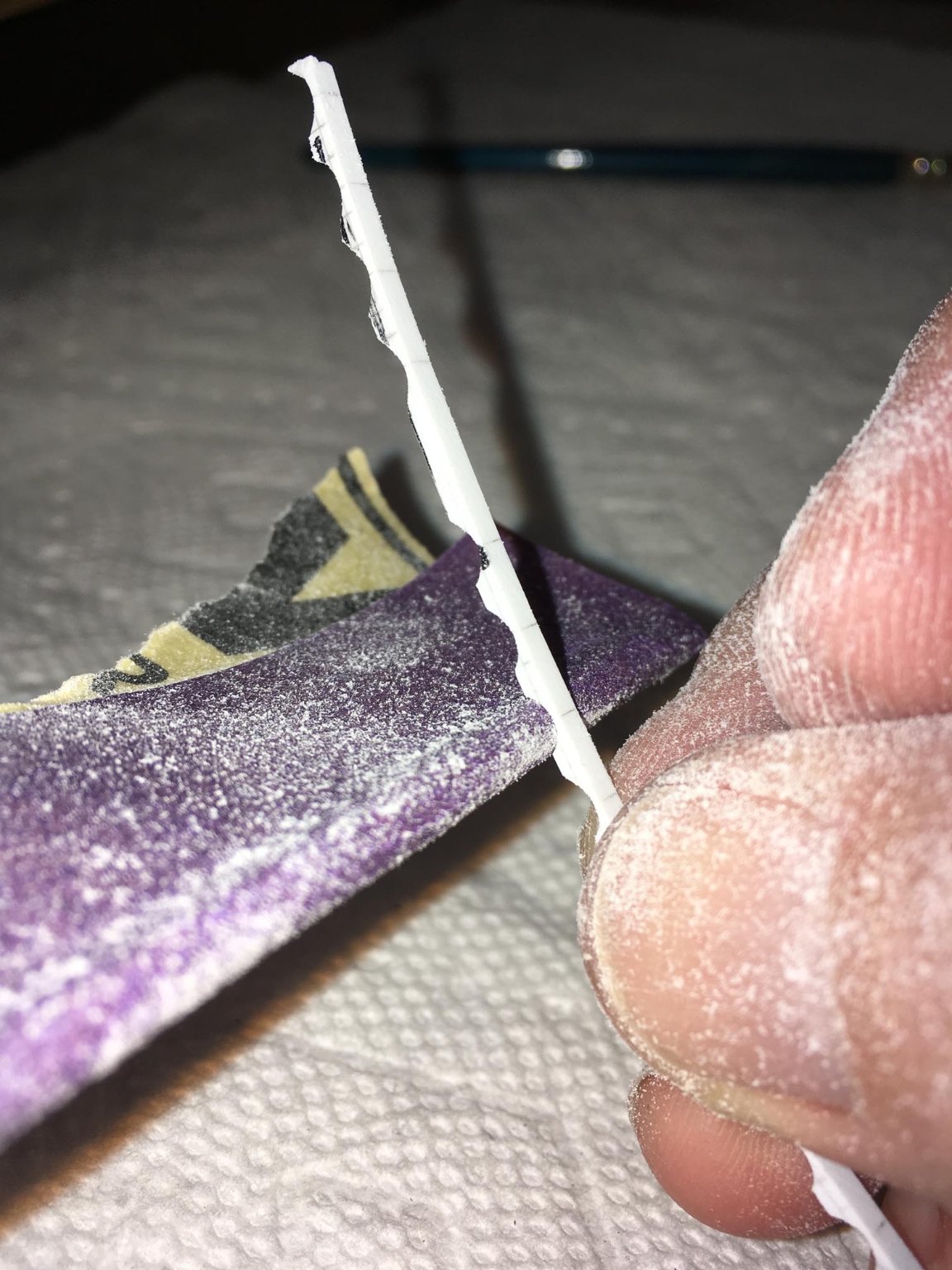
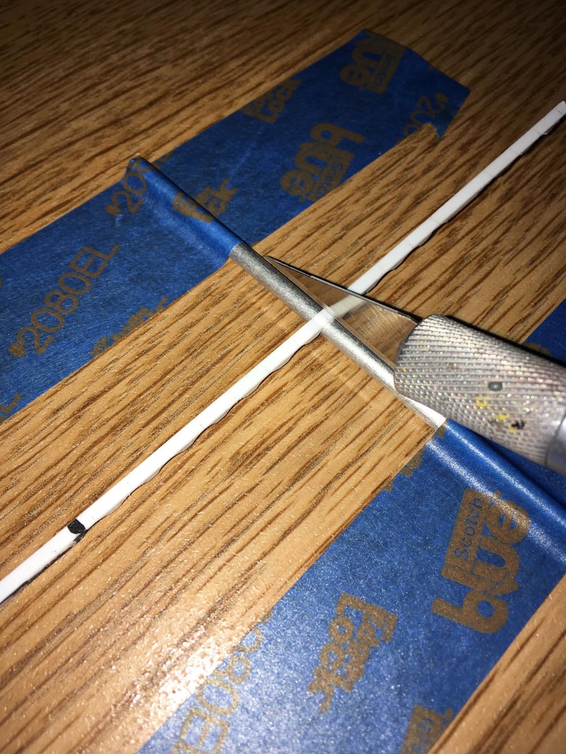
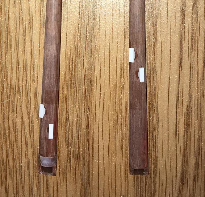
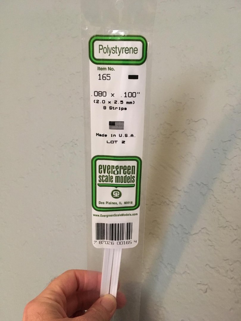
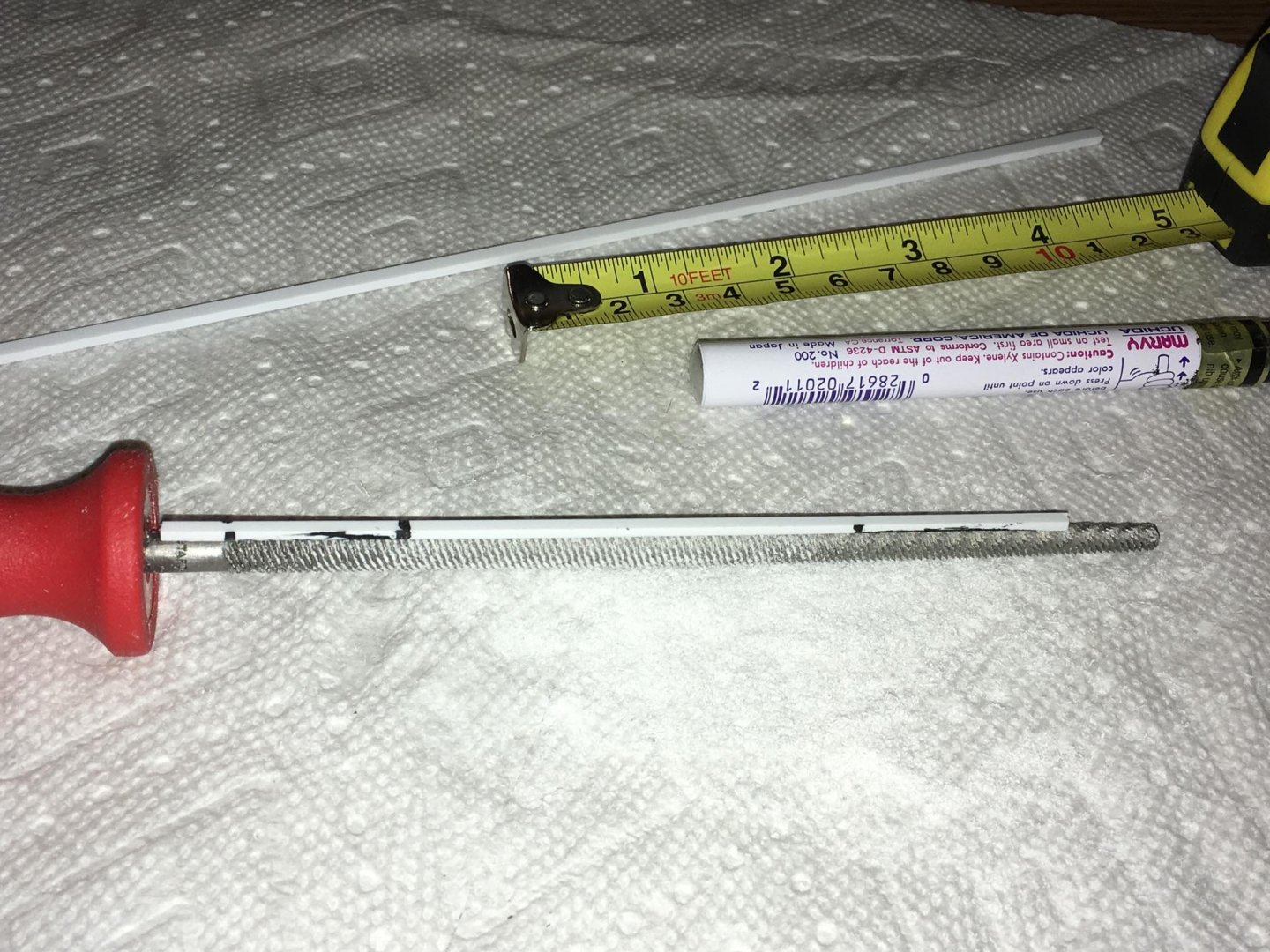
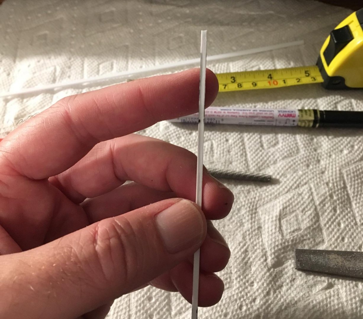
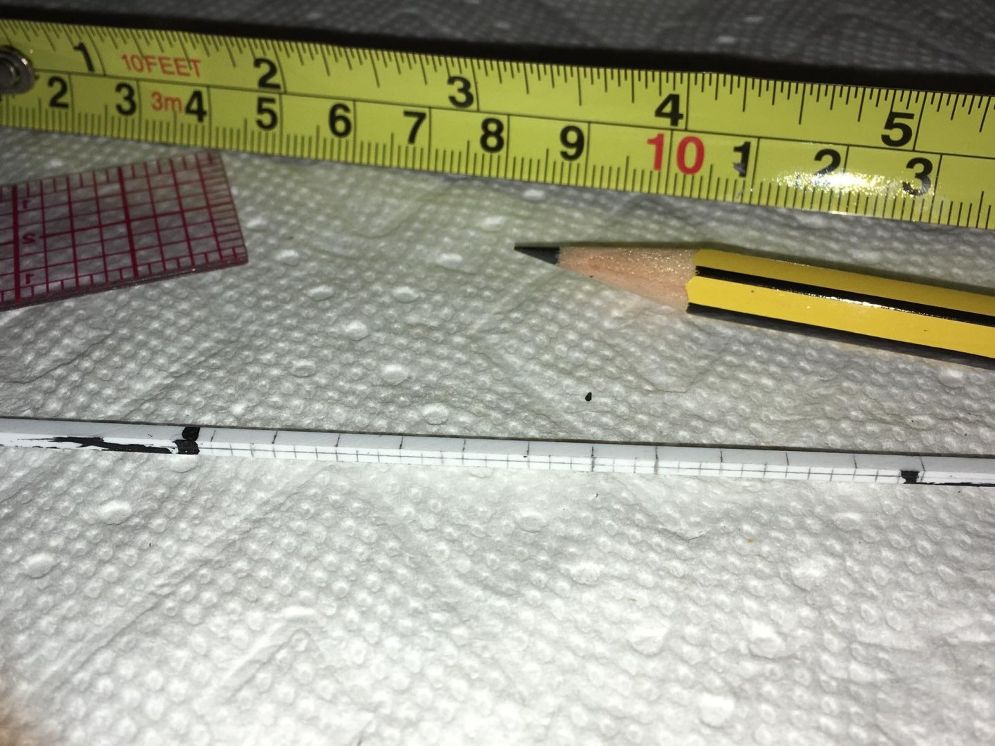
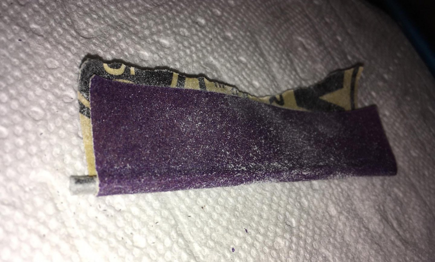
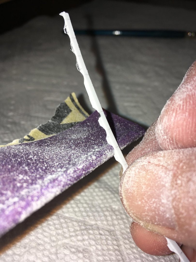
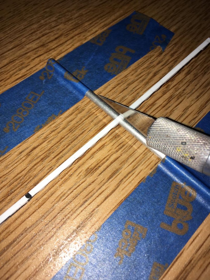
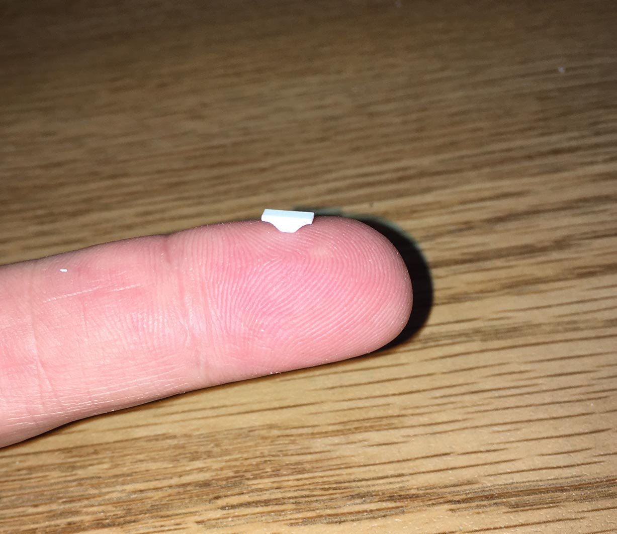
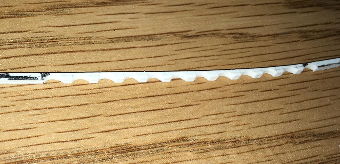
I made some cleats to mount on the foremast, mainmast and bowsprit. These will eventually be used to belay certain rigging lines. Since the kit is plastic, I used polystyrene strips to make the cleats, since there would be a good, strong bond between the cleat and the mast, which could handle some tension. fil I first filed down a strip with a round file so that the undersurface of the cleats would be concave. This helps it conform to the "roundness" of the mast or bowsprit: Here is how the undersurface appears after filing: Then I made measurements on the strip for the cleats, marking with a pencil: I wrapped a piece of 150 grit sandpaper, with double-sided tape on the back of it, around a remnant aluminum rod piece: Using the markings on the strip as a guide, I sanded the strip against the sandpapered rod to make "arches" in between the attachment points of the soon-to-be cleats: With each arch held over the aluminum rod for support, I separated the cleats with a knife: Below is a sample of a cleat. Each cleat is small -- only 6 mm long, 2 mm wide, and less than 2 mm high: I know that these cleats do not have a stylized appearance with tapered "horns" as you may see on sailing ships, but to try doing that by carving these tiny plastic parts may cause them to look less symmetric and/or consistent. It would also be rather difficult to hold them in place to carve them -- they move easily when whittled, even when grasped with tweezers. Despite the shape, my version will be very functional for belaying rigging.
-
Patrick, congratulations on this amazing build — you packed so much realistic detail into this small scale, and it has been an inspiration for my own plastic ship build. Your skill and precision are exemplary!
-
There is a glue called Craftics Thickened Cement #33 that I have used for gluing small pieces of polycarbonate to styrene on my plastic model, and since it is not too thin, I think maybe one could mask the edges of the polycarbonate being joined to protect the surfaces from overflow and “spider web” strings from extruding glue, without the glue creeping under the tape. The surfaces would probably need to be masked on the inside and the outside of the seams. Here is a link: https://www.craftics.net/ShowItems.aspx?Category=80&ParentCategory=3 Craftics makes thin glues too that can be used on polycarbonate. I do not know if any of these are available outside of the United States, however.
-
It’s great to see in your photos how the white glue works to stiffen the sails in a “billowed” shape by treating them over the plastic ones. This is coming along very nicely!
- 35 replies
-
- 1
-

-
- english man o war
- revell
- (and 2 more)
-
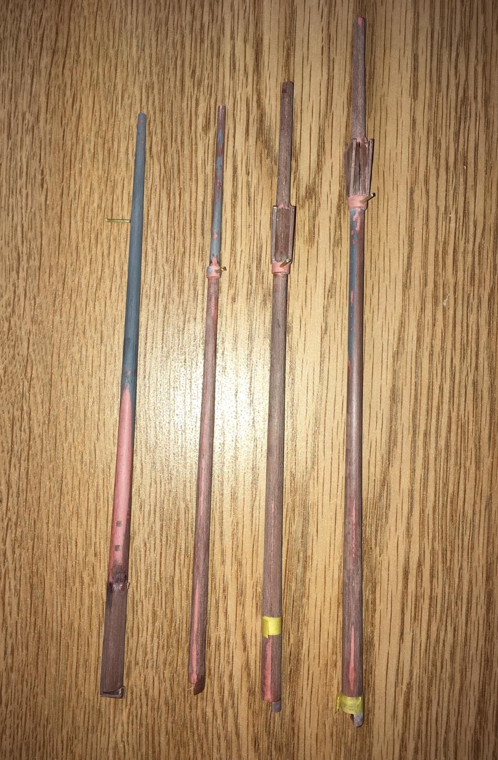
In addition to the problem where the seams did not line up correctly, there were a lot of variations in the contour or "roundness" of the masts and bowsprit (although they really are not completely round anyway -- more like "oval"). I wanted to make them as consistent as possible, so this required a lot of work. I used a steel-filled epoxy (J-B Weld) and also Bondo Glazing & Spot Putty to smooth things out: The brass rods that you see protruding from them (glued in place with steel-filled epoxy) will later be shortened and used to hold the spars up to the masts and bowsprit so that it will be easier to do the rigging. The two squares on the bowsprit (far left) are to expose styrene under the putty in order to attach a couple of styrene pieces with solvent glue (more on that later).

-
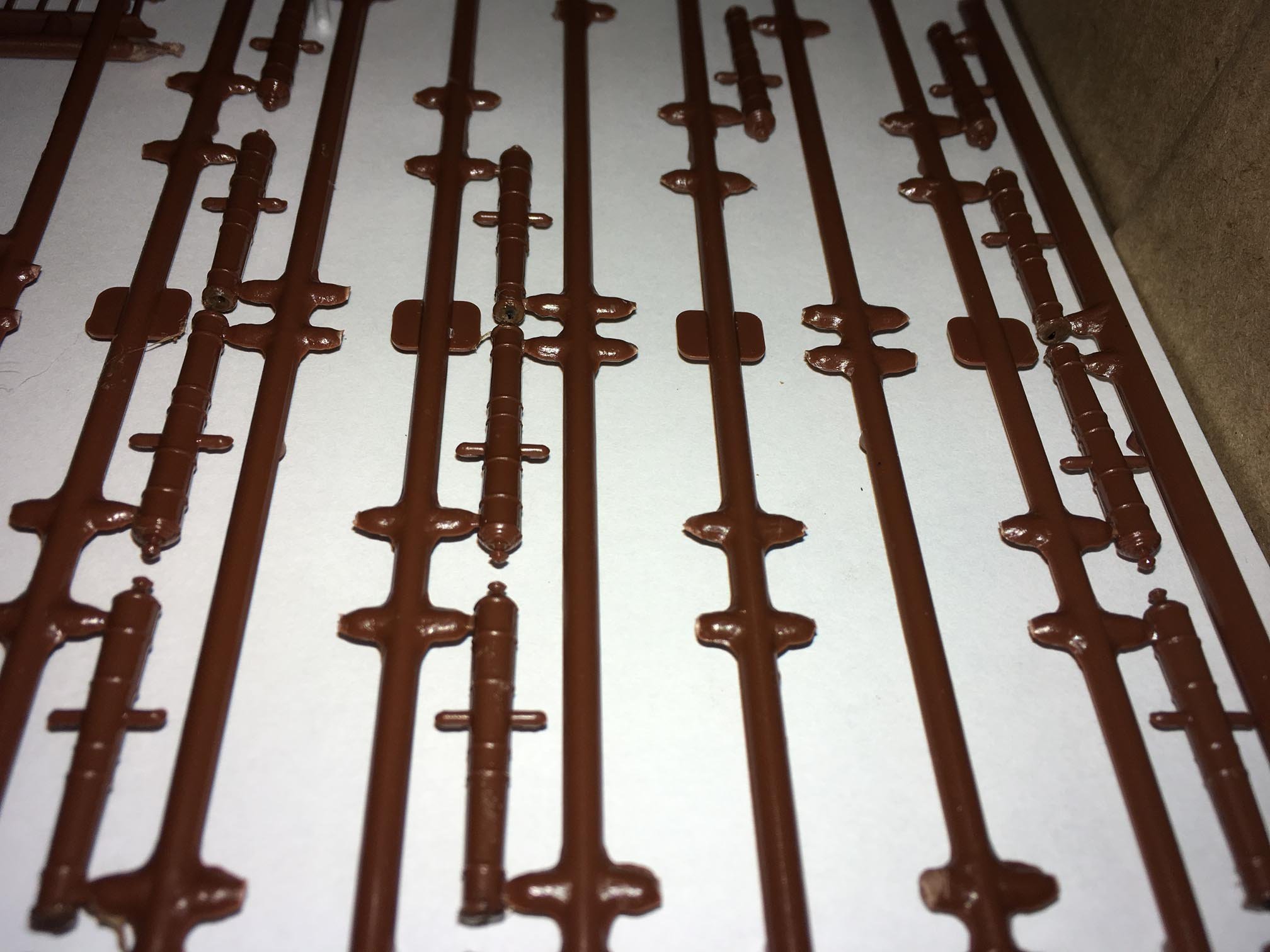
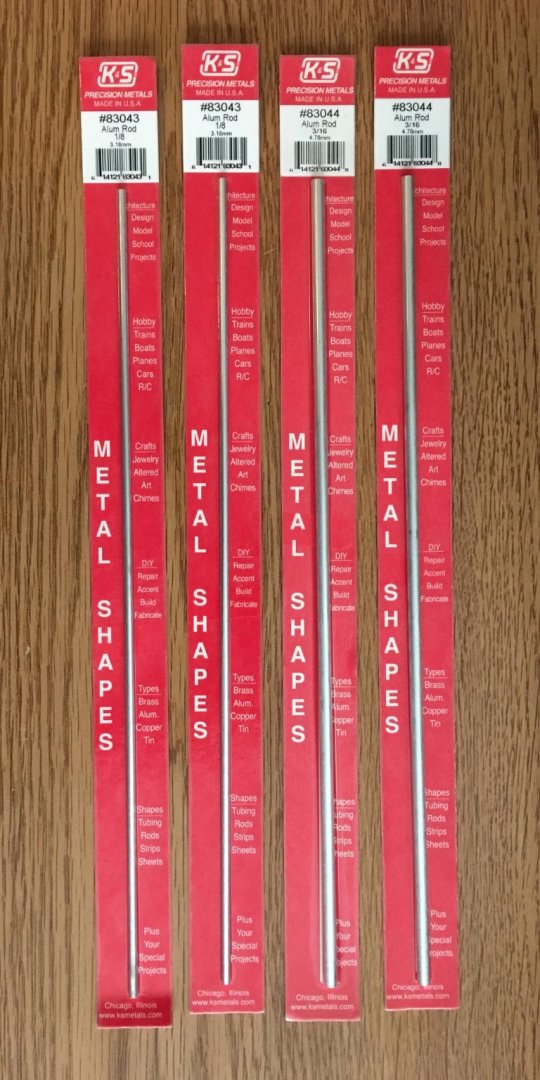
I decided to take a break from painting for a while, and looked ahead to the masts and spars. The plastic in this kit is a bit pliable, with an almost "waxy" texture to it when handled. (I remember styrene in kits that I built in my youth being more rigid, and maybe even brittle at times). Since this plastic bends, the spars and upper masts may be a little difficult to manage when rigging is applied with a little tension. Even the lower masts and bowsprit are thin and may bend. Other members on this forum have used wood on the inside to strengthen them. What I decided to do is make my own spars and upper masts from walnut dowels (I will do this later on in the build). I will use the plastic lower masts (foremast, mainmast, mizzenmast) and bowsprit that were supplied with the kit, and I have already worked with them quite a bit to strengthen them and try to eliminate the seams as much as I could. I could have also made these from wood, but I want a good styrene-to-styrene bond at the partners, and I want them to have the intended rake, which is already there in the plastic masts. Here is how they looked on the sprues -- the halves have fairly thin walls: I also am using interior supports, but I decided to go with aluminum rather than wood: I sanded the aluminum rods down so that they fit in the masts and bowsprit, but also had to sand out any plastic fitting pins within them: I used 30 minute epoxy to set the supports into the masts and bowsprit (the white stuff in the foremast is epoxy putty where I had made the rod too short): I set the free halve over the ones with the rods with epoxy and later glued the seams with Tamiya Extra Thin Cement: Unfortunately, the seams did not match up very well, because the walls are of varying thickness on the same mast, and the inner rods would not let me slide the masts halves slightly across each other to line them up (you can see where the seams mismatch below): By the way, I also removed the "rings" around the masts and bowsprit that I think were supposed to be wooldings. I want to make my own wooldings out of rigging line. Also notice above that the cheeks on the mizzenmast (third from the left) are gone. I removed them, because I do not want a "top" on my mizzenmast. Rather, it will be something like this, without a topmast (although I may put a flagstaff on top):


-
They are called channels or chain-wales. Looking great 👍🏻!
- 28 replies
-
- 3
-
-
- Black Pearl
- Zvezda
- (and 2 more)
-
Here is a link to a website that may help explain why boat or ship masts are slanted forward or aft: https://www.woodenboat.com/whiskey_plank/why-mast-rake So you may see it on other models as well.
- 165 replies
-
- 1
-
-
- english galleon
- revell
- (and 2 more)
-
I can see your photos now and I would like to congratulate you on a great job (especially for your first sailing ship)! I love the weathering — including the barnacles — and your attention to detail. Bravo!
- 28 replies
-
- 4
-
-
- Black Pearl
- Zvezda
- (and 2 more)
-
The bit of rigging on the bowsprit to which you are pointing in the last picture is called gammoning. Here is a link that has some information on how to do it: I am not sure of the reason, but all of the other pictures that you placed in your post are not visible to me (they are just blank). What technique did you use to place them in the post (e.g. drag and drop, or copy and paste)? Maybe some of the other people viewing the post can see them?
- 28 replies
-
- 3
-
-
- Black Pearl
- Zvezda
- (and 2 more)
-
Here is another thought for the windows, if you would like: You can repaint them black first, and let them thoroughly dry. Then, mix a VERY small amount of white acrylic into a bit of your clear polyurethane varnish, so that when you paint that mixture over the black, you will get a very slightly hazy gloss — this can simulate a slightly dirty glass window outside the dark cabin.
- 265 replies
-
- 1
-
-
- Golden Hind
- Airfix
- (and 1 more)
-
When following Backer's log on his scratch-built Golden Hind 1/45 scale, I wondered how I would also solve the problem of the mainstay coming down to the beakhead, because the rigging instructions by Revell do not do it that way, and I wanted to follow a plan more like that outlined by Peter Kirsch in his Galleon book, referenced previously in this log. So I did a crude preliminary test, but keep in mind, doing anything concrete with the rigging will still be a long way off for me: Fortunately, it looks like I will likely be able to run the mainstay under the railing at the front of the forecastle and loop it around the the bowsprit at the stempost. And, rather than making it go to one side or the other of the foremast, I will most likely have two limbs of the mainstay loop around either side of it.

-
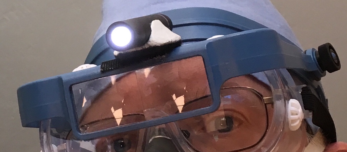
Robert, The topics linked by Ryland Craze have some good recommendations. I am afraid that my own pair of magnifiers is not as fancy as what is discussed in those links. I have plastic lenses, not glass, but so far, they have lasted over three years. This is what I have: I cannot remember the brand name. For the lighting, I use an LED penlight that takes a single AAA battery (I use rechargeable, which last over 2 hours at a time). The LED penlight is mounted on the frame of the magnifier by means of velcro so that I can remove it to change the battery. The white “cradle” for the penlight that allows a flat connection for the velcro of the penlight to the velcro of the frame was made of epoxy putty.
-
Bill, I really like your weathering on the hull. The simulated caulking of the deck boards is a nice touch.
- 35 replies
-
- 1
-
-
- english man o war
- revell
- (and 2 more)