


wool132
-
Posts
117 -
Joined
-
Last visited
Content Type
Profiles
Forums
Gallery
Events
Posts posted by wool132
-
-
-
-
I'm at the same place at the same time with the same problem on my build. Care to share the secret to success, wealth, and eternal happiness?
Jonathan
-
-
-
Option 1: order replacement kit
Option 2: fabricate replacement parts (use the cut outs on the plywood sheet as a guide)
Option 3: order the Pram (not on backorder, at least not now) and put in a request for Dory replacement parts using their online system. Work on the Pram until the parts arrive. By then, you’ll have broken some parts on the Pram and you can work on the Dory until the Pram parts arrive. Rinse, repeat. 🙂
If you’ve got the spare $60 or so, I’d go with #3, otherwise #2 would be worth a try.
Jonathan
- RMillet, mtaylor and Ryland Craze
-
 3
3
-
It looks like Tablecloth Red
")
Jonathan
-
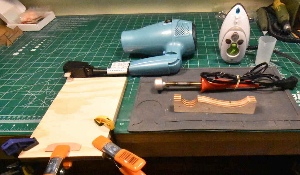
I've lined off the hull. I have Chuck's Medway Longboat planking instructions. I also have my bending board, three clamps, hair dryer, travel iron, plank bender, and silicon pad, so what could possibly go wrong?
Well!
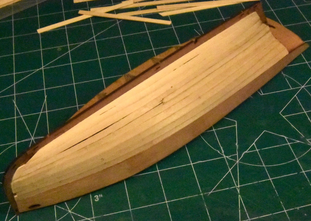
I mis-measured at the stern so I wound up a little short on the total plank width, even using the full width available for the nine planks. As a result, I had to add a steeler a little below the future water-line. There is also a glaring gap towards the bow. Lord knows how THAT got there!
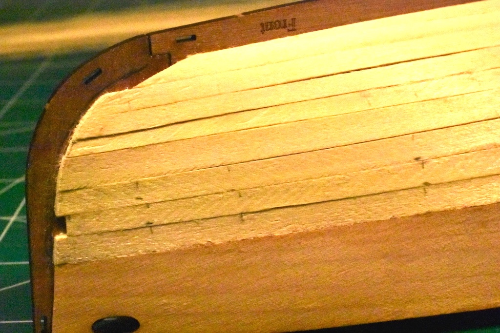
Speaking of the bow, here's a close-up showing the two planks that are significantly shorter than they should be. I started with the garboard plank and the one right below it then the first two strakes just below the bulwark. I struggled with determining where the planks should end at the stem until I ran across a comment by Craigie65 in Glomar's Nisha Blog. He suggested dry fitting part 58 to determine this. I fitted the part and drew a line to show the ending point. That helped a lot when fitting the five remaining planks in the middle.
The other problem at the prow is that I've tapered some of the planks so that they vary significantly in width. One is rather narrow and another, right below, is much too wide. I suppose I was trying to get back on track with my tick marks.
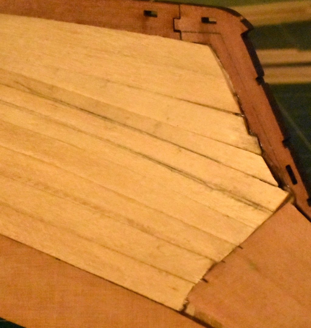
Meanwhile the stern didn't seem to come out too bad (after inserting the steeler). I used the hair-dryer-twist method so that the planks didn't need much pressure to fit in place. I like using woodworker's glue wherever possible. I dispense it with a hypodermic needle, smear it around a little into a thin layer using a toothpick, and finger-clamp the plank in place for a minute or two (or three if it's being cranky) until the glue dries enough to hold it in position, then move on to the next plank. I imagine distributing my fingers across the length of the plank is good practice if I ever decide to learn how to play the recorder. 🙂
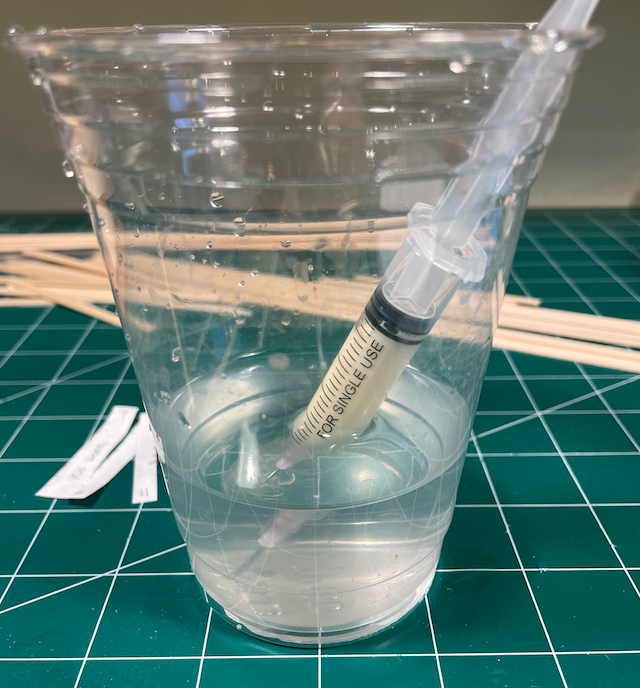
I discovered that storing the syringe in a bit of water keeps the glue from drying out and clogging up the 18G needle, though I do need to press out a little glue before using it to get rid of any watery bits at the tip.
So, feeling rather chagrined but still hopeful, I'm moving on to the port side for another attempt.
As usual, any advice and counsel would be greatly appreciated!
Jonathan
-
Adding my voice to the chorus of Thanks! for providing all of this well documented detail on your build 😄
Jonathan
-
-
Thanks for your offer of assistance (Andyrew) and words of encouragement (AJohnson and Theodosius)!! And thanks to all the others for the likes 🙂. The Dory and Pram projects helped a lot as an organized introduction to the techniques of modeling (and travails too, such as the gudgeons and pintles on the Pram ☹️).
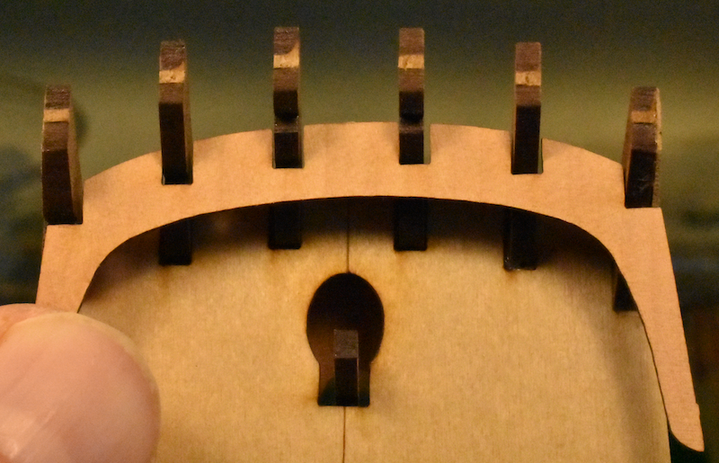
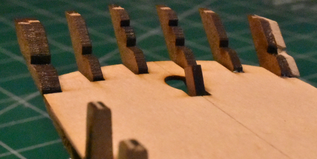
Step 45: While fairing the hull I held the engraved deck (#29) up against the stern timbers to gauge the amount of wood to sand off the two outer stern frames (#24). This was taken after I finished sanding. You can see that I had to remove quite a bit from my (uncharred) replacement part.
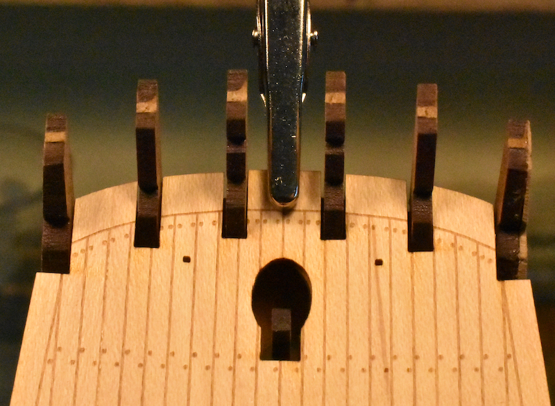
I also held the transit rail (#47) in place as another check.
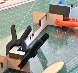
Step 51: Bending and gluing the stern counter fortunately didn't present any special problems. I soaked the piece a long time and used as many clamps as would fit around the edges while it dried.
Step 61: This model looks like an excellent opportunity to try and apply the full Chuck Pissarro plankification process as described in chapter two of the Medway Longboat instruction manual. I cut up a bunch of tick strips, printed the planking fan, got a roll of tape, sharpened my pencil, and lined off the hull.
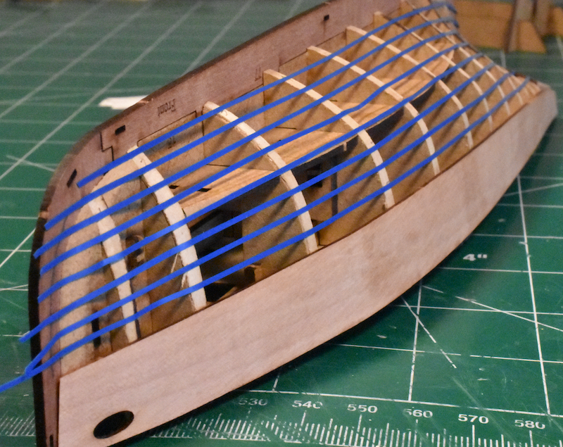
Some of the strips went askew while moving the hull around to take some pictures: I fixed 'em before the final marking of the hull. So next up is planking the starboard side. I'll finish that before tackling the port side.
In other news, we've already harvested about 25 stalks from our small asparagus bed and more keep coming up. Yum!

Jonathan
-
I put in a request for some replacement parts for my Bounty Launch build around a month ago and I’m still waiting too. In the meantime, I’ve been working on the Nisha and Bluenose while they get things sorted out.
They’re probably getting lots of emails by now about the status of replacement parts in their backlog, so to me their response sounds sincere and accurate, albeit frustrating.
I used Google StreetView for their current address and the place sure looks small given the size of their staff, equipment, and inventory of raw materials, finished parts, and kits. Hopefully they’ll have more room in their new location (don’t see how they could operate with less!).
Jonathan
- mtaylor and thibaultron
-
2
-
-
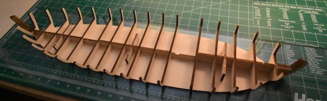
I started this build on 11-Mar-22 by laying out the pieces needed for the first part of the build.
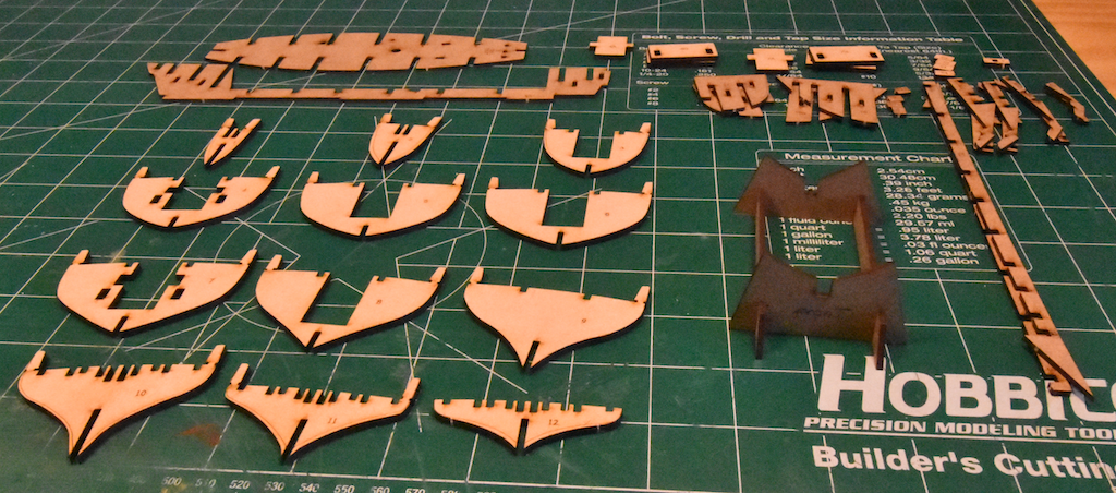
Things were going along quite nicely for three days until I brushed the aft end of the hull against the edge of my workbench and broke off portions of parts 22, 23 and 24 on the port side.
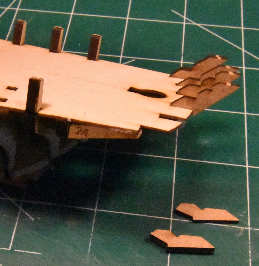
I did what Grey did (see post 7) after a similar accident and glued part 22 back on with a couple of supporting pieces but I was stumped on what to do about the other two. There wasn't enough of them left to ensure things would be in alignment after a repair. I stopped working on the ship until I could figure out a way to recover from the mishap.
What I finally decided to do is fabricate a replacement for part 24 using the cut-out as a guide, glue the remainder of part 23 to this, then glue the whole thing onto the model.
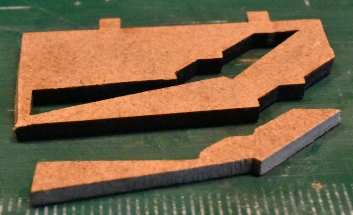
This is the replacement part 24 made from a scrap piece of 2 mm MDF. It took about 90 minutes to file and sand to shape so that it would fit in the cut-out.
With the replacement glued in, it's on to Step 45 as I repeat the mantra: "I will finish this model. I will finish this model. I will finish ..."
Jonathan
-
Bill M.: Fine with me. Lots better than starting a new thread on the same subject!
- mtaylor, Canute and Bill Morrison
-
3
-
Following with interest. This kit is on my list of builds to tackle in the mid-distant future.
-
If you haven't already found it, the build log by GenericDave is an excellent reference. The complete version is on his external website, SuburbanShipModeler.
As you stumble along, remember the inspiring words of Homer Simpson: "Trying is the first step towards failure".
Jonathan
- Ryland Craze and Keith Black
-
2
-
-
Parallel universe: I’m doing the same triad, also working on the Nisha.
Adding to the two posts above, watch out for those frames hanging off the stern as you muck about with the hull. I didn’t need to drop it on the floor like Grey did in post #7; I just knocked the back against the edge of my workbench.
I haven’t started planking so I don’t yet know how good a fairing job I’ve actually done. Being double-planked, I’m hoping there’ll be a lot of forgiveness (one of the reasons for doing this kit before something else like the English Pinnace).
Jonathan
-
-
-
Step 17: Cut, fit, and glue twelve 1/16” x 1/2” floorboards, six on each side of the keel. Mark the edges of the boards with a Number 2 (HB) pencil to simulate caulking (some recommend only doing this on one edge for each pair; I did both edges). The ends of the floorboards were cut square but they came out bowed after I sanded them to fit. Word gets back that a Northwest Short Line True Sander would do a better at keeping the edge square when adjusting the length than the hand-held sander I used:
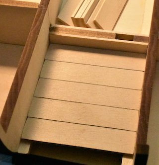
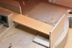
To make sure they're the same length, I cut the first of the floorboards to the desired length and then used Nirvana's jig idea for use with the chop saw:
a) Place this first board (the template) on top of a 1/16" x 1/2" wood strip, making sure the ends on the right are aligned: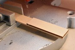
b) push both boards towards the chop saw blade until the left end of the template touches the saw blade then tighten the saw's clamp to keep the wood strip in place:
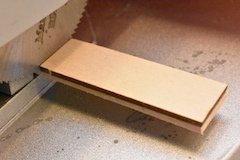
c) Remove the template:
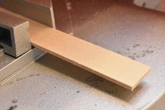
d) Align an authentic, genuine, certified fnkershner bulkhead brace (
- see prior post) with the right end of the wood strip:
e) With the brace taped in place, push the wood strip against it and cut:
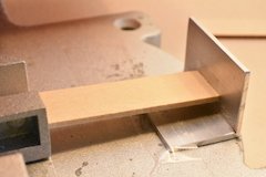
Check to make sure it's the right length then cut the rest of the twelve pieces.
Step 18: Glue part 29 (PA-8) to the aft side of bulkhead 12 and part 29A (PA-8) to the fore side of bulkhead 11 on both the starboard and port sides: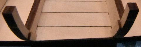
Jonathan
- Tom E, Elijah, Jim Rogers and 1 other
-
4
-
Step 11: Number the bulkheads (parts 1-16) with a soft pencil while they are still in their boards. Some modelers recommend numbering all of the parts, not just the bulkheads.
Step 12: Remove the two bulkhead 8s from PA-4. Carve and sand the bevels into the bulkheads using the engraved bevel lines as a guide (see Detail 2-4).
Step 13: Clamp the bottom of the hull to a piece of glass to ensure it stays flat while you assemble the bulkheads (I didn't do this and now the bottom is slightly warped. Nothing serious but fooey.).
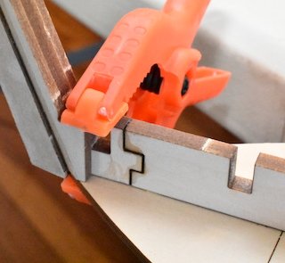
Step 14: Glue the bulkheads to the keel. Make sure they are square to the keel (use fnkershner bulkhead braces, angle plates, Lego blocks, index card corners, etc). Make sure the two-piece bulkheads fit properly to the edge of the bottom by shaving the center joint of the bulkhead if needed. While the glue is drying prepare another bulkhead pair. Work out from the first bulkhead pair on alternating sides fore and aft (8, 7, 9, 6, 10, 5, 11, etc).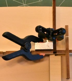
Step 15: Glue a pair of part 27s (PA-8) to either side of the keel in the forward cockpit (see Detail 2-5).
Step 16: Glue four 3/16” square members. The picture below shows all six parts from these two steps being clamped in place. The stem is off to the upper left.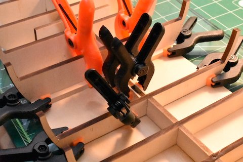
- Tom E and Jim Rogers
-
2
-
Note: The instructions that come with the kit say to now glue parts 20, 21, and 22 to the keel. I think this should be done later. Delaying allows the use a straight edge when trying to keep the keel straight as it is glued to the bottom in Step 9 below.
Step 7: Match bottom parts 23S (PA-2) and 23P (PA-1) and apply a strip of Scotch tape to the joint. Turn over and apply a few spots of glue to the joint.
Step 8: Glue part 24 (PA-1). Clip all three parts to a piece of glass to make sure the assembly is flat while the glue dries.Note: the next step also deviates from the manual. My keel was slightly bent. By gluing it to the bottom at the ends there was no place for the wood to go when I tried to center the middle of the keel on the bottom: the glued ends forced it into an S-shape because the wood wouldn't compress. A better way would be to glue the stem then the center and the stern last.
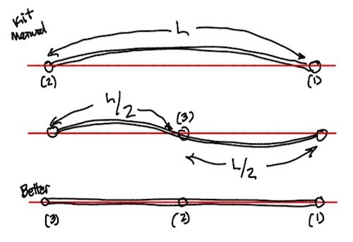
Step 9: Carefully align and center the keel. Glue it to the bottom at the stem using CA glue. Next, align the keel using a straight edge and use CA glue to fasten it at the center. Finally, glue the stern while you continue to keep the keel straight using a straight edge.
Step 10: Glue parts 20, 21, and 22 (PA-5) to the keel and to the bottom while making sure they are perpendicular to the keel. (The picture below was taken when following the kit instructions, not the revised steps above. I've included it as an example of how these parts can be kept perpendicular to the keel while the glue dries.)
Jonathan
- Jim Rogers and AntonyUK
-
2

Lowell Grand Banks Dory by RMillet - FINISHED - Model Shipways - 1:24
in - Kit build logs for subjects built from 1851 - 1900
Posted
The parts list on page three of the manual lists 2 12" lengths of 1⁄16" square basswood, so there should be another piece kicking around somewhere -or- time to get in touch with ModelExpo.
Jonathan